

Sony Walkman PCM-M1 Service Manual
PCM-M1
SERVICE MANUAL
DIGITAL AUDIO TAPE RECORDER
MICROFILM
Model Name Using Similar Mechanism TCD-D100
Tape Transport Mechanism Type MT-D100-128
t
w
AEP Model
US Model
SPECIFICATIONS
Tape Digital audio tape
Recording time Standard: 120minutes
Long-play mode: 240minutes (with DT-120)
Sampling frequency 48kHz, 44.1kHz, 32kHz
Quantization Standard: 16-bit linear
Long-play mode: 12-bit non linear
Frequency response
Standard: Fs 48kHz 20-22,000Hz (±1.0dB) (LINE IN)
Fs 44.1kHz 20-20,000Hz (±1.0dB) (LINE IN)
Fs 32kHz 20-14,500Hz (±1.0dB) (LINE IN)
Long-play mode: Fs32kHz 20-14,500Hz (±1.0dB) (LINE
IN)
Signal to noise ratio Standard: more than 87dB
Long-play mode: more than 87dB
(1kHz IHF-A, LINE IN)
Dynamic range Standard: more than 87dB
(1kHz IHF-A, LINE IN)
Total harmonic distortion
Standard: less than 0.008% (1kHz, 22kHz LPF, LINE IN)
Long-play mode: less than 0.09% (1kHz, 22kHz LPF,
LINE IN)
Wow and flutter
Below measurable limit (less than ±0.001% W.PEAK)
Input
Output
Input/Output DIGITAL • REMOTE I/O jack (special jack)
Jack type
stereo minijack
Impedance
MIC 4.7kΩ
LINE IN 47kΩ
Rated input level
MIC 1.4mV
LINE IN 500mV
Minimum input level
MIC 0.3mV
LINE IN 120mV
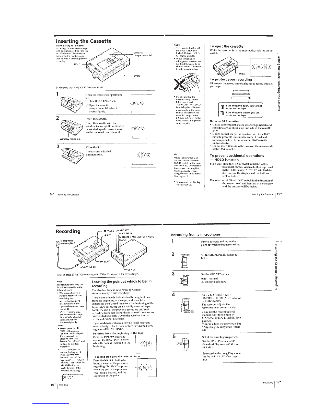
MIC/
LINE IN
Jack type
stereo
minijack
Impedance
220Ω
16Ω
Rated output
500mV
87mV
Minimum output level
–
15mW+15mW
LINE OUT
REMOTE /2
Load impedance
10kΩ
16Ω
Digital input/ output, remote control operation and
timer-activated operation is possible by connection
with an adaptor kit to this jack.
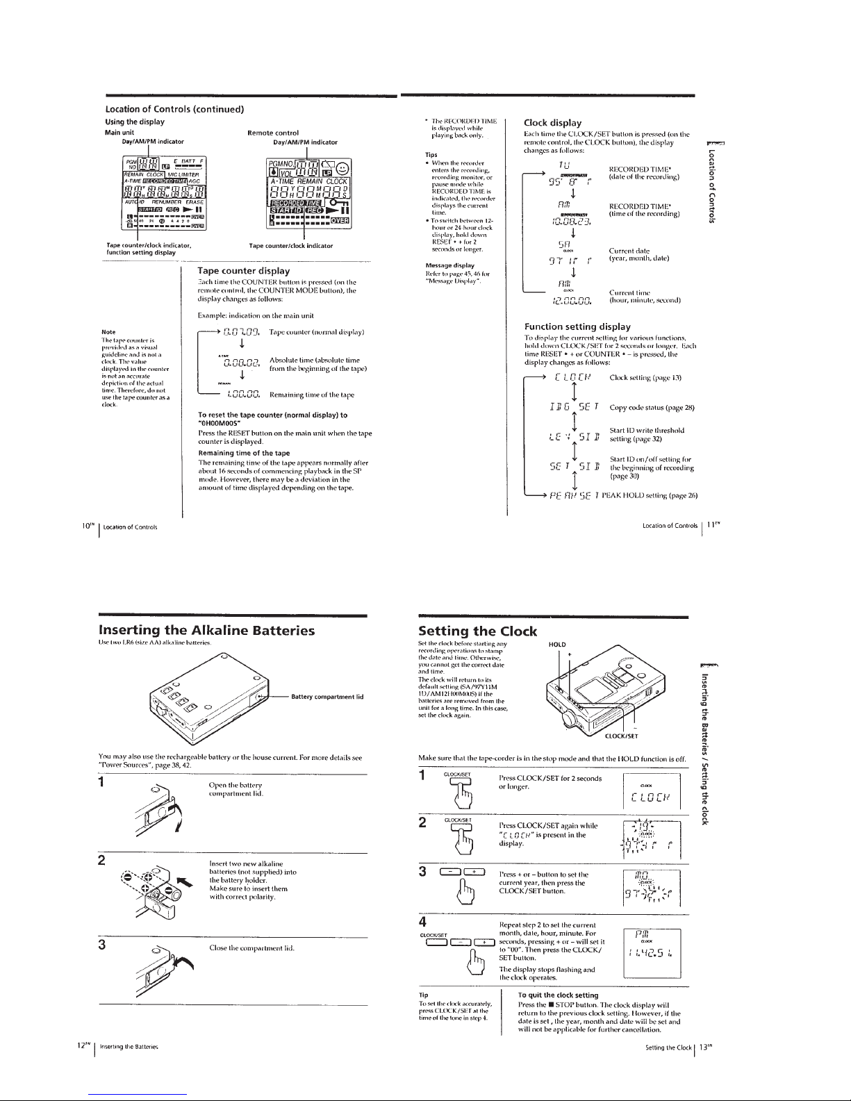
Power requirements • Two R6 (size AA) alkaline batteries (not supplied)
• Two nickel metal hydride rechargeable battery
(Supplied)
DC IN 4.5V jack accepts:
the Sony AC power adaptor AC-E45HG
(Supplied)
the car battery cord DCC-E245 (not supplied)
for use with 12V/24V car battery.
Battery life See “Replacing the batteries” (page 11).
Power consumption 0.9W
Dimension Approx. 80×117.3×29.2mm (3
1
/
4
× 4
5
/
8
× 1
3
/
16
in)
(w/h/d) not incl. projecting parts and controls
Mass Main unit: Approx. 290g (10.3oz)
When using the main unit: Approx. 395g (14oz.)
incl.headphones with remote control, rechargeable
batteries and a cassette
Supplied accessories
• AC power adaptor (1)
• Charger adaptor (1)
• Nickel Metal Hydride Rechargeable battery NH-D100 (2)
• Headphones with a remote control (1)
• DAT cleaning cassette (1)
• Microphone plug adaptor (monaural phone jack × 2→ stereo miniplug) (1)*
• Optical cable (special jack ↔ rectangular-shaped optical input/output) (1)*
• Battery carrying case (1)
• Carrying case (1)
* Supplied only to the European model.
Design and specifications are subject to change without notice.

— 2 —
TABLE OF CONTENTS
1. GENERAL································································
3
2. DISASSEMBLY
2-1. P ANEL ASSY, LOWER ··················································· 14
2-2. MAIN BOARD ································································14
2-3. LID ASSY , CASSETTE ··················································· 15
2-4. PC BOARD UNIT, SYSTEM CONTROL ······················ 15
2-5. CABINET········································································· 16
2-6. BRACKET ASSY, MD ···················································· 16
2-7. CHASSIS ASSY······························································· 17
2-8. DRUM ASSY ··································································· 17
3. ADJUSTMENTS
3-1. ADJUSTMENTS······························································18
3-2. MECHANICAL ADJUSTMENTS ·································· 23
3-3. ELECTRICAL ADJUSTMENTS ···································· 24
4. DIAGRAM
4-1. BLOCK DIAGRAM – MD SECTION — ······················· 26
4-2. BLOCK DIAGRAM – AUDIO SECTION —················· 29
4-3. IC BLOCK DIAGRAM ··················································· 31
4-4. PRINTED WIRING BOARD ··········································34
4-5. SCHEMATIC DIAGRAM —MAIN SECTION —········· 39
4-6. SCHEMATIC DIAGRAM —AUDIO SECTION — ······ 42
4-7. IC PIN FUNCTION ························································· 45
5. EXPLODED VIEWS
5-1. CABINET SECTION ······················································· 49
5-2. CASSETTE HOLDER SECTION ··································· 50
5-3. MACHANISM SECTION 1 ············································ 51
5-4. MACHANISM SECTION 2 ············································ 52
6. ELECTRICAL PARTS LIST ··································· 53
Notes on chip component replacement
• Never reuse a disconnected chip component.
• Notice that the minus side of a tantalum capacitor may be
damaged by heat.
Flexible Circuit Board Repairing
• Keep the temperature of soldering iron around 270˚C
during repairing.
• Do not touch the soldering iron on the same conductor of the
circuit board (within 3 times).
• Be careful not to apply force on the conductor when soldering
or unsoldering.
— 3 —
SECTION 1
GENERAL
This section is extracted
from instruction manual.
— 4 —
— 5 —
— 6 —
— 7 —
— 8 —
— 9 —
— 10 —
— 11 —
— 12 —
— 13 —
— 14 —
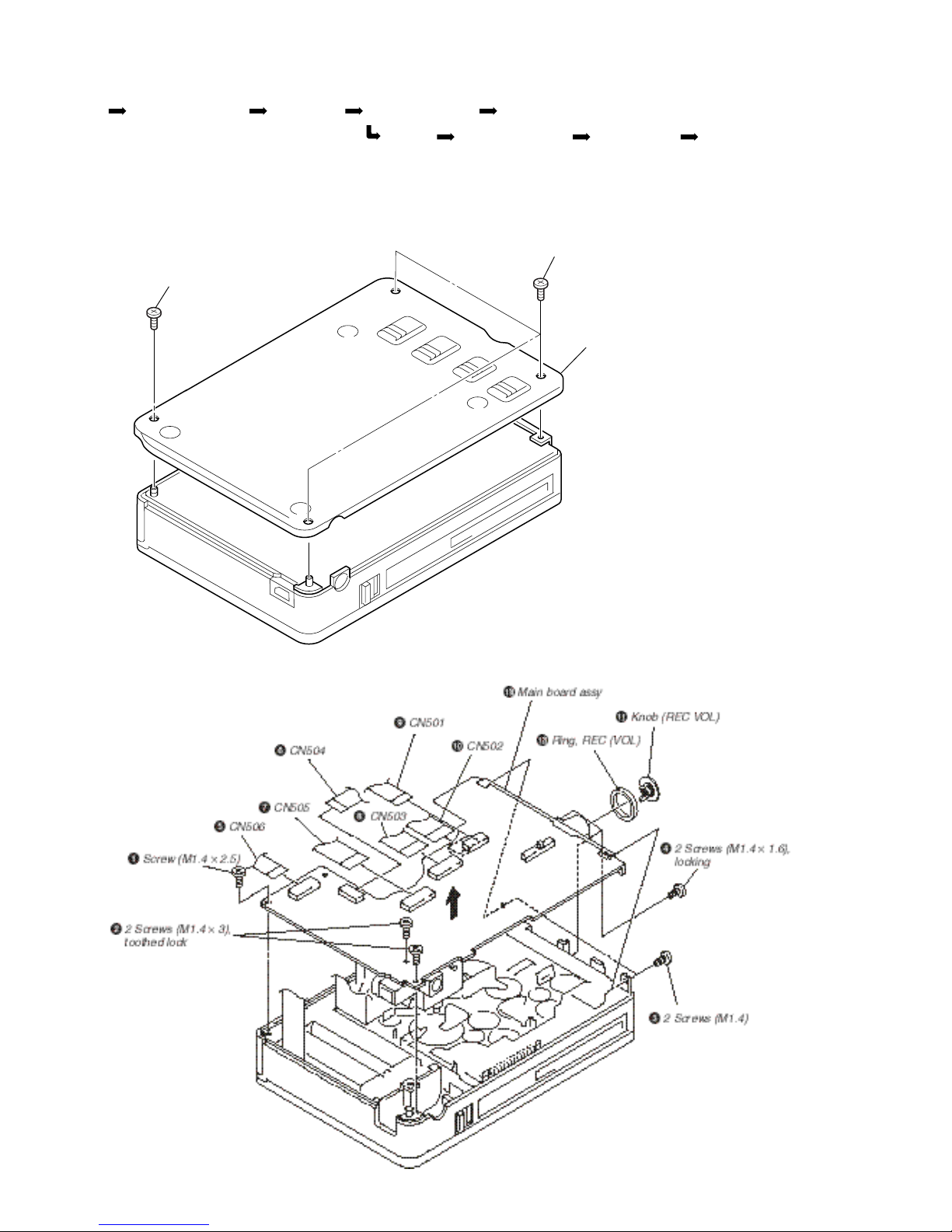
SECTION 2
DISASSEMBLY
2-1. PANEL ASSY, LOWER
2-2. MAIN BOARD
Note: When assembling it, align the slide switch position, and
assemble it.
CABINET BRACKET ASSY, MD CHASSIS ASSY DRUM ASSY
SET PANEL ASSY, LOWER MAIN BOARD LID ASSY, CASSETE PC BOARD UNIT, SYSTEM CONTROL
1 Screw (M1.4 × 2.5)
2
3 Screws (M1.4 × 1.6)
3
Panel assy, lower
 Loading...