

Sony Walkman NWZ-A726, Walkman NWZ-A728, NWZ-A728B, Walkman NWZ-A729, NWZ-A726B Service Manual
...
SERVICE MANUAL
Sony Corporation
Audio Business Group
Published by Sony Techno Create Corporation
SPECIFICATIONS
DIGITAL MEDIA PLAYER
9-889-029-01
2008B05-1
©
2008.02
US Model
NWZ-A726/A726B/A728/A728B/A729
Canadian Model
NWZ-A726/A728
E Model
Australian Model
Tourist Model
East European Model
NWZ-A726/A728/A729
Ver. 1.0 2008.02
NWZ-A726/A726B/A728/
A728B/A729
Photo: NWZ-A728
ATRAC is trademark of Sony Corporation.
“WALKMAN” and “WALKMAN” logo are registered trademarks of Sony
Corporation.
and are trademarks of Sony Corporation.
Microsoft, Windows, Windows Vista and Windows Media are trademarks or
registered trademarks of Microsoft Corporation in the United States and/or
other countries.
A
dobe, Adobe Reader and Adobe Flash Player are trademarks or registered
trademarks of Adobe Systems Incorporated in the United States and/or other
countries.
MP
EG Layer-3 audio coding technology and patents licensed from
Fraunhofer IIS and Thomson.
IBM and PC/AT are registered trademarks of International Business
Machines Corporation.
M
acintosh is a trademark of Apple Inc.
QuickTime and the QuickTime logo are trademarks or registered trademarks
of Apple Inc., used under license therefrom.
Pentium is a trademark or a registered trademark of Intel Corporation.
This software is based in part on the work of the Independent JPEG Group.
THIS PRODUCT IS LICENSED UNDER THE MPEG-4 VISUAL PATENT
PORTFOLIO LICENSE FOR THE PERSONAL AND NON-COMMERCIAL
USE OF A CONSUMER FOR
(i)
ENCODING VIDEO IN COMPLIANCE WITH THE MPEG-4 VISUAL
STANDARD (“MPEG-4 VIDEO”) AND/OR
(ii) DECODING MPEG-4 VIDEO THAT WAS ENCODED BY A
CONSUMER ENGAGED IN A PERSONAL AND NON-COMMERCIAL
ACTIVITY AND/OR WAS OBTAINED FROM A VIDEO PROVIDER
LICENSED BY MPEG LA TO PROVIDE MPEG-4 VIDEO.
NO LICENSE IS GRANTED OR SHALL BE IMPLIED FOR ANY OTHER
USE. ADDITIONAL INFORMATION INCLUDING THAT RELATING TO
PROMOTIONAL, INTERNAL AND COMMERCIAL USES AND
LICENSING MAY BE OBTAINED FROM MPEG LA, LLC. SEE
HTTP://WWW.MPEGLA.COM
THIS PRODUCT IS LICENSED UNDER THE AVC PATENT PORTFOLIO
LICENSE FOR THE PERSONAL AND NON-COMMERCIAL USE OF A
CONSUMER TO
(i)
ENCODE VIDEO IN COMPLIANCE WITH THE AVC STANDARD
(“AVC VIDEO”) AND/OR
(ii) DECODE AVC VIDEO THAT WAS ENCODED BY A CONSUMER
ENGAGED IN A PERSONAL AND
NON-COMMERCIAL ACTIVITY AND/OR WAS OBTAINED FROM A
VIDEO PROVIDER LICENSED TO PROVIDE AVC VIDEO. NO LICENSE
IS GRANTED OR SHALL BE IMPLIED FOR ANY OTHER USE.
ADDITIONAL INFORMATION MAY BE OBTAINED FROM MPEG LA,
L.L.C. SEE HTTP://MPEGLA.COM
US a
nd foreign patents licensed from Dolby Laboratories.
All other trademarks and registered trademarks are trademarks or registered
trademarks of their respective holders. In this manual,
TM
and ® marks are not
specified.
This product is protected by certain intellectual property rights of Microsoft
Corporation. Use or distribution of such technology outside of this product is
prohibited without a license from Microsoft or an authorized Microsoft
subsidiary.
Content providers are using the digital rights management technology for
Windows Media contained in this device (“WM-DRM”) to protect the integrity
of their content (“Secure Content”) so that their intellectual property, including
copyright, in such content is not misappropriated.
This device uses WM-DRM software to play Secure Content (“WM-DRM
Software”). If the security of the WM-DRM Software in this device has been
compromised, owners of Secure Content (“Secure Content Owners”) may
request that Microsoft revoke the WM-DRM Software’s right to acquire new
licenses to copy, display and/or play Secure Content. Revocation does not alter
the WM-DRM Software’s ability to play unprotected content. A list of revoked
WM-DRM Software is sent to your device whenever you download a license
for Secure Content from the Internet or from a PC. Microsoft may, in
conjunction with such license, also download revocation lists onto your device
on behalf of Secure Content Owners.
Program ©2008 Sony Corporation
Documentation ©2008 Sony Corporation
Supported file format
Music
File format MP3(MPEG-1 Layer3) file format, ASF file format, MP4 file format, Wave-Riff file
format
File extension MP3 (.mp3), WMA*
1
(.wma), AAC-LC*2 (.mp4, .m4a, .3gp), Linear PCM (.wav)
Codec MP3 Bit rate: 32 to 320 kbps (Supports variable bit rate (VBR))
Sampling frequency*
3
: 32, 44.1, 48 kHz
WMA*
1
Bit rate: 32 to 192 kbps (Supports variable bit rate (VBR))
Sampling frequency*
3
: 44.1 kHz
AAC-LC*
2
Bit rate: 16 to 320 kbps (Supports variable bit rate (VBR))*
4
Sampling frequency*3: 8, 11.025, 12, 16, 22.05, 24, 32, 44.1, 48 kHz
Linear PCM Bit rate: 1,411 kbps
Sampling frequency*
3
: 44.1 kHz
Video
File format MP4 file format, “Memory Stick” video format
File extension .mp4, .m4v
Codec Video AVC
(H.264/AVC)
Profile: Baseline Profile
Level: Max. 1.3
Bit rate: Max. 768 kbps
MPEG-4 Profile: Simple Profile
Bit rate: Max. 2,500 kbps
Frame rate: Max. 30 fps
Resolution: Max. QVGA (320 × 240)
Audio AAC-LC Channel number: Max. 2 channels
Sampling frequency*
3
: 24, 32, 44.1, 48 kHz
Bit rate: Max. 288 kbps per 1 channel
File size Max. 2 GB
The number of files Max. 1,000
Photo*
5
File format Compatible with DCF 2.0/Exif 2.21file format
File extension .jpg
Codec Profile: Baseline Profile
Number of pixels: Max. 4,000 × 4,000 pixels (16,000,000 pixels)
The number of files Max. 10,000
*1WM-DRM 10 files are compatible.
*
2
Copyright protected AAC-LC files cannot be played back.
*
3
Sampling frequency may not correspond to all encoders.
*
4
Non-standard bit rates or non-guaranteed bit rates are included depending on the
sampling frequency.
*
5
Some photo files cannot be played back, depending on their file formats.
– Continued on next page –
NWZ-A726/A726B/A728/A728B/A729
2
Maximum recordable number of songs and time (Approx.)
The approximate times are based on the case in which you transfer or record only 4
minutes songs (not including videos and photos) in the MP3 format. Other playable audio
file format song numbers and times may differ from MP3 format.
NWZ-A726 NWZ-A728
Bit rate Songs Time Songs Time
48 kbps 2,450 163 hr. 20 min. 5,050 336 hr. 40 min.
64 kbps 1,850 123 hr. 20 min. 3,750 250 hr. 00 min.
128 kbps 925 61 hr. 40 min. 1,850 123 hr. 20 min.
256 kbps 460 30 hr. 40 min. 945 63 hr. 00 min.
320 kbps 370 24 hr. 40 min. 755 50 hr. 20 min.
NWZ-A729
Bit rate Songs Time
48 kbps 10,200 680 hr. 00 min.
64 kbps 7,650 510 hr. 00 min.
128 kbps 3,800 253 hr. 20 min.
256 kbps 1,900 126 hr. 40 min.
320 kbps 1,500 100 hr. 00 min.
NWZ-A726B NWZ-A728B
Bit rate Songs Time Songs Time
48 kbps 2,450 163 hr. 20 min. 5,050 336 hr. 40 min.
64 kbps 1,850 123 hr. 20 min. 3,750 250 hr. 00 min.
128 kbps 925 61 hr. 40 min. 1,850 123 hr. 20 min.
256 kbps 460 30 hr. 40 min. 945 63 hr. 00 min.
320 kbps 370 24 hr. 40 min. 755 50 hr. 20 min.
Maximum recordable time of videos (Approx.)
The approximate recordable times are estimated in the case where only videos are
transferred. The time may differ, depending on the conditions under which the player is
used.
NWZ-A726 NWZ-A728 NWZ-A729
Bit rate Time Time Tim e
Video Format: 384 kbps
15 hr. 00 min. 30 hr. 40 min. 62 hr. 00 min.
Audio Format: 128 kbps
Video Format: 768 kbps
8 hr. 30 min. 17 hr. 30 min. 35 hr. 30 min.
Audio Format: 128 kbps
NWZ-A726B NWZ-A728B
Bit rate Time Time
Video Format: 384 kbps
15 hr. 00 min. 30 hr. 40 min.
Audio Format: 128 kbps
Video Format: 768 kbps
8 hr. 30 min. 17 hr. 30 min.
Audio Format: 128 kbps
Maximum recordable number of photos that can be transferred (Approx.)
Max. 10,000
Recordable number of photos may be less depending on file sizes.
Capacity (User available capacity)*
1
NWZ-A726: 4 GB (Approx. 3.57 GB = 3,840,638,976 bytes)
NWZ-A728: 8 GB (Approx. 7.30 GB = 7,840,956,416 bytes)
NWZ-A729: 16 GB (Approx. 14.7 GB = 15,841,820,672 bytes)
NWZ-A726B: 4 GB (Approx. 3.57 GB = 3,840,573,440 bytes)
NWZ-A728B: 8 GB (Approx. 7.30 GB = 7,840,890,880 bytes)
*
1
Available storage capacity of the player may vary.
A portion of the memory is used for data management functions.
Output (headphones)
Frequency response
20 to 20,000 Hz (when playing data file, single signal measurement)
Interface
Headphone: Stereo mini-jack
WM-PORT (multiple connecting terminal): 22 pins
Hi-Speed USB (USB 2.0 compliant)
Operating temperature
5 °C to 35 °C (41 °F to 95 °F)
Power source
• Built-in rechargeable lithium-ion battery
• USB power (from a computer via the supplied USB cable)
Charging time
USB-based charging
Approx. 3 hours (full charge), Approx.1.5 hours (approx. 80 %)
Battery life (continuous playback)
By setting as follows, a longer battery life can be expected.
The times below are approximated when “New Song Pop Up”, “Clear Stereo”, “DSEE(Sound
Enhancer)”, “Dynamic Normalizer”, “Equalizer” and “VPT(Surround)” are deactivated,
and “Screensaver” is set to “Blank.”
Furthermore, for videos, the time approximated when the brightness of the screen is set to
“3.”
NWZ-A726/A726B/A728/A728B/
A729
Music
Playback at MP3 128 kbps Approximately 36 hours
Playback at WMA 128 kbps Approximately 35.5 hours
Playback at AAC-LC 128 kbps Approximately 33.5 hours
Playback at Linear PCM 1411 kbps Approximately 34.5 hours
Video
Playback at MPEG-4 384 kbps Approximately 10 hours
Playback at MPEG-4 768 kbps Approximately 9 hours
Playback at AVC 384 kbps Approximately 8 hours
Playback at AVC 768 kbps Approximately 8 hours
Display
2.4-inch, TFT color display with white LED-backlight, QVGA (240 × 320 pixels), 262,144
colors
Dimensions (w/h/d, projecting parts not included)
50.2 × 93.6 × 9.3 mm (2 × 3 3/4 × 3/8 inches)
Dimension (w/h/d)
51.0 × 93.9 × 9.3 mm (2 1/8 × 3 3/4 × 3/8 inches)
Mass
Approx. 58 g (Approx. 2.1 oz)
Supplied Accessories
Headphones (1)
USB cable (1)
Earbuds (Size S,L) (1)
Attachment (1)
Use when connecting the player to the optional cradle, etc.
Stand (1)
CD-ROM*1*2 (1)
– BestBuy Digital Music Store (NWZ-A726B/A728B)
– MP3 Conversion Tool
– Media Manager for WALKMAN
– Windows Media Player 11
– Operation Guide (PDF file)
Quick Start Guide (1)
*1Do not attempt to play this CD-ROM in an audio CD player.
*2Depending on the country/region in which you have purchased the player, the
bundled software may be different.
Design and specifications are subject to change without notice.

NWZ-A726/A726B/A728/A728B/A729
3
Notes on chip component replacement
• Never reuse a disconnected chip component.
• Notice that the minus side of a tantalum capacitor may be damaged by heat.
Flexible Circuit Board Repairing
• Keep the temperature of soldering iron around 270 °C during
repairing.
• Do not touch the soldering iron on the same conductor of the
circuit board (within 3 times).
• Be careful not to apply force on the conductor when soldering
or unsoldering.
1. SERVICING NOTES ............................................. 3
2. GENERAL .................................................................. 5
3. DISASSEMBLY
3-1. Disassembly Flow .......................................................... 6
3-2. Cover (Rear), Rear Assy ................................................. 6
3-3. Battery ............................................................................. 7
3-4. MAIN Board ................................................................... 7
3-5. LCD Assy ........................................................................ 8
4. TEST MODE ............................................................ 9
5. DIAGRAMS
5-1. Block Diagram - MAIN Section - ................................... 17
5-2. Block Diagram
- PANEL, POWER SUPPLY Section - ........................... 18
5-3. Printed Wiring Board - MAIN Board (Side A) - ............ 20
5-4. Printed Wiring Board - MAIN Board (Side B) - ............ 21
5-5. Schematic Diagram - MAIN Board (1/6) - ..................... 22
5-6. Schematic Diagram - MAIN Board (2/6) - ..................... 23
5-7. Schematic Diagram - MAIN Board (3/6) - ..................... 24
5-8. Schematic Diagram - MAIN Board (4/6) - ..................... 25
5-9. Schematic Diagram - MAIN Board (5/6) - ..................... 26
5-10. Schematic Diagram - MAIN Board (6/6) - ..................... 27
5-11. Schematic Diagram - SW Board (1/2) - .......................... 28
5-12. Schematic Diagram - SW Board (2/2) - .......................... 29
5-13. Printed Wiring Board - SW Board - ................................ 30
6. EXPLODED VIEWS
6-1. Cover (Rear) Section ...................................................... 42
6-2. Rear Assy Section ........................................................... 43
6-3. MAIN Board Section ...................................................... 44
6-4. Front Section ................................................................... 45
7. ELECTRICAL PARTS LIST .............................. 46
TABLE OF CONTENTS
CAUTION
Danger of explosion if battery is incorrectly replaced.
Replace only with the same or equivalent type.
UNLEADED SOLDER
Boards requiring use of unleaded solder are printed with the leadfree mark (LF) indicating the solder contains no lead.
(Caution: Some printed circuit boards may not come printed with
the lead free mark due to their particular size)
: LEAD FREE MARK
Unleaded solder has the following characteristics.
• Unleaded solder melts at a temperature about 40 °C higher
than ordinary solder.
Ordinary soldering irons can be used but the iron tip has to be
applied to the solder joint for a slightly longer time.
Soldering irons using a temperature regulator should be set to
about 350 °C.
Caution: The printed pattern (copper foil) may peel away if the
heated tip is applied for too long, so be careful!
• Strong viscosity
Unleaded solder is more viscous (sticky, less prone to fl ow)
than ordinary solder so use caution not to let solder bridges
occur such as on IC pins, etc.
• Usable with ordinary solder
It is best to use only unleaded solder but unleaded solder may
also be added to ordinary solder.
NOTE THE CN601, CN602, IC301, IC302, IC305, IC501,
IC503, IC508, IC509, IC601, IC602, IC701, IC751, IC752,
IC901 AND IC902 ON THE MAIN BOARD REPLACING
CN601, CN602, IC301, IC302, IC305, IC501, IC503, IC508,
IC509, IC601, IC602, IC701, IC751, IC752, IC901 and IC902
on the MAIN board cannot exchange with single. When CN601,
CN602, IC301, IC302, IC305, IC501, IC503, IC508, IC509,
IC601, IC602, IC701, IC751, IC752, IC901 and IC902 on the
MAIN board are damaged, exchange the entire mounted board.
NOTE THE CN801, CN881 AND IC801 ON THE SW
BOARD REPLACING
CN801, CN881 and IC801 on the SW board cannot exchange with
single. When CN801, CN881 and IC801 on the SW board are damaged, exchange the entire mounted board.
SECTION 1
SERVICING NOTES
System Requirements
Computer
IBM PC/AT or compatible computer preinstalled with the following Windows operating
systems*
1
:
Windows XP Home Edition (Service Pack 2 or later) / Windows XP Professional
(Service Pack 2 or later) / Windows Vista Home Basic / Windows Vista Home Premium
/ Windows Vista Business / Windows Vista Ultimate
Not supported by 64 bit version OS.
Not supported by OSs other than above.
*
1
Excluding OS Versions not supported by Microsoft.
CPU: Pentium 4 1.0 GHz or higher
RAM: 512 MB or more
Hard Disk drive: 380 MB or more of available space
Display:
Screen Resolution: 800 × 600 pixels (or higher) (recommended 1,024 × 768 or higher)
Colors: 8 bit or higher (16 bit recommended)
CD-ROM drive (supporting Digital Music CD playback capabilities using WDM)
To create original CDs, a CD-R/RW drive is required.
Sound board
USB port (Hi-Speed USB is recommended)
Microsoft .NET Framework 2.0 or 3.0, QuickTime 7.2, Internet Explorer 6.0 or 7.0,
Windows Media Player 10 or 11 (Windows Media Player 11 recommended. Some
computers that already have Windows Media Player 10 installed may encounter file
limitation (AAC, video files, etc.) that can be transferred by dragging and dropping.).
A
dobe Flash Player 8 or higher needs to be installed.
Broadband Internet connection is required to use Electronic Music Distribution (EMD)
or to visit the web site.
We do not guarantee operation for all computers even if they meet the above System
Requirements.
Not supported by the following environments:
P
ersonally constructed computers or operating systems
An environment that is an upgrade of the original manufacturer-installed operating
system
Multi-boot environment
Multi-monitor environment
Macintosh

NWZ-A726/A726B/A728/A728B/A729
4
NOTE THE MAIN BOARD REPLACING
When the MAIN board is replaced, format it according to the following.
COLOR VARIATION
Model Destination
Color
Black White Pink Silver Gold
NWZ-A726
US
zz
US (CircuitCity)
zz
CND
zzz
E, AUS, JE
zz z
MX3
zz
EE
zzzz
NWZ-A726B US (BestBuy)
zz
NWZ-A728
US
zz
US (CircuitCity)
z
CND
zz
E, AUS, JE
zzz
MX3
z
EE
zzzz
NWZ-A728B US (BestBuy)
zz
NWZ-A729
US
z
E, AUS, JE
z
EE
z
Formatting Memory
(Format)
You can format the built-in flash memory of the player.
If the memory is formatted, all data and settings will be erased. Be sure to
verify the data stored in memory prior to formatting and export any important
data to the hard disk of your computer.
Settings
5-way button
BACK/HOME
button
Note
This function is only available in the pause mode.
Press and hold the BACK/HOME button in the pause mode until the
Home menu appears.
Press the /// button to select (Settings), and then press
the button to conrm.
Press the /// button to select “Common Settings,” and then
press the button to conrm.
The list of “Common Settings” options appears.
Press the /// button to select “Format,” and then press the
button to conrm.
“All data including songs will be deleted. Proceed?” appears.
Press the / button to select “Yes,” and then press the button
to conrm.
“All data will be deleted. Proceed?” appears.
Press the / button to select “Yes,” and then press the button
to conrm.
While the memory is being formatted, an animated display appears.
When initialization finishes, “Memory formatted.” appears.
To cancel the operation
Select “No” in step or and press the button to confirm. You can also
cancel the operation by pressing the BACK/HOME button in step
or .
Note
Do not format the built-in flash memory using software or Windows Explorer.
• Abbreviation
AUS : Australian model
CND : Canadian model
EE : East European model
JE : Tourist model
MX3 : Argentina, Brazilian, Chilean, Colombian, Ecuadorean, Panamanian, Peruvian and Venezuelan models
NWZ-A726/A726B/A728/A728B/A729
5
SECTION 2
GENERAL
Parts and Controls
Front
BACK/HOME button*
1
Press to go up one list screen level, or
to return to the previous menu.
Press and hold the BACK/HOME
button to display the Home menu .
Headphone jack
For connecting the headphones.
Insert the jack pin until it clicks into
place. If the headphones are
connected improperly, the sound
from the headphones may not sound
right.
WM-PORT jack
Use this jack to connect the supplied
USB cable, or optional peripheral
devices, such as supported
accessories for the WM-PORT.
5-way button*
2
Starts playback and enables
navigation of the player’s on-screen
menus.
Display
The display may vary, depending on
functions.
VOL +*
2
/– button
Adjusts the volume.
HOLD switch
You can protect the player against
accidental operation by using the
HOLD switch when carrying it. By
sliding the HOLD switch to the
direction of the arrow , all
operation buttons are disabled. If you
slide the HOLD switch to the
opposite position, the HOLD
function is released.
OPTION/PWR OFF button*
1
Displays the option menu .
If you press and hold the OPTION/
PWR OFF button, screen turns off
and the player enters standby mode.
If you press any button while the
player is in standby mode, the “Now
Playing” screen, etc., appears and the
player is ready for operation.
Furthermore, if you leave the player
in standby mode for about a day, the
player turns completely off
automatically. If you press any button
when the player is turned off, the
start up screen appears first, then the
“Now Playing” screen appears.
Note
• The player consumes battery power
very slightly even when it is in standby
mode. Therefore, the player might
turn completely off in a short time,
depending on the power remaining in
the battery.
Strap hole
Used to attach a strap (sold
separately). You can attach the
supplied stand and a strap at the same
time.
*
1
Functions marked with on the
player are activated if you press and hold
the corresponding buttons.
*
2
There are tactile dots. Use them to help
with button operations.
Rear
RESET button
Resets the player when you press the
RESET button with a small pin, etc. .
Accessory hole (type I)
Used to attach the supplied stand or
the optional accessories.
Using the supplied stand
You can stand up the player using the
supplied stand.
Notes
• When standing the player with the
stand, be careful not to press down or
knock the player.
• Stand up the player horizontally as
shown. Do not stand it up vertically.
This section is extracted
from instruction manual.
NWZ-A726/A726B/A728/A728B/A729
6
SECTION 3
DISASSEMBLY
• This set can be disassembled in the order shown below.
3-1. DISASSEMBLY FLOW
Note: Follow the disassembly procedure in the numerical order given.
3-2. COVER (REAR), REAR ASSY
SET
3-2. COVER (REAR),
REAR ASSY
(Page 6)
3-3. BATTERY
(Page 7)
3-4. MAIN BOARD
(Page 7)
3-5. LCD ASSY
(Page 8)
two screws (M1.4)
two ornamental screws
screw
(M1.4)
two claws
rear assy
two
claws
lid (ACC)
claw
claw
cover (rear)
NWZ-A726/A726B/A728/A728B/A729
7
3-3. BATTERY
Note: This illustlation sees the battery assy from back.
3-4. MAIN BOARD
Note: This illustration sees the MAIN board from the back.
battery
adhesive sheet (BATT)
BATT wire sheet
connector
(CN901)
battery connector
lead wire
(red)
lead wire
(black)
spacer (line in)
Note 2: When removing battery,
don't remove by the impossible power.
Note 3: Adhesive sheet (BATT) cannot re-used.
Please replace to brand-new part ones
adhesive sheet (BATT) is removed.
Note 1: When installing battery connector,
please be careful about the color
of the lead wires as shown in a figure
and install battery connector.
screw
(B1.4)
spacer (line in)
claw
BATT wire sheet
R
connector (CN601)
connector (board to board)
connector
(board to board)
spacer (line in)
connector (CN901)
HP flexible
print board
(CN301)
RI
MAIN board
RB
cushion
PWB
sheet key (CN602)
escutcheon (CN)
RT
spacer (PWB-S)
RE
sheet (WM-P)
RG
cushion (WM-P)
RH
cushion PWB
RE
sheet (WM-P)
battery connector
lead wire
(red)
lead wire
(black)
Note 1: When installing battery connector,
please be careful about the color
of the lead wires as shown in a figure
and install battery connector.
Note 2: Please install or
remove connector
(board to board)
vertically.
NWZ-A726/A726B/A728/A728B/A729
8
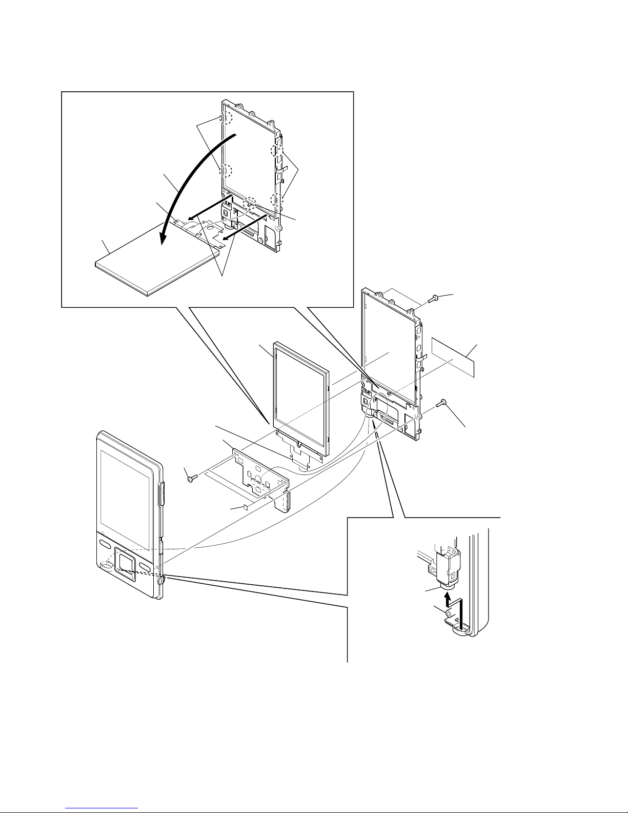
3-5. LCD ASSY
two screws
(M1.4)
two spacers
(WM-P)
two claws
two claws
SW board
LCD flexible board
(CN801)
sheet (LCD-B)
two screws
(B1.4)
screw
(B1.4)
RE
LCD assy
R
Open the LCD assy
in the direction of the arrow.
waterproof jack
Remove the waterproof jack
in the direction of the arrow.
RB
boss
RT
Pull out the
LCD flexible board.
LCD flexible board
LCD assy
9
NWZ-A726/A726B/A728/A728B/A729
SECTION 4
TEST MODE
1. SETTING THE TEST MODE
Note: Perform the test mode in the state of 3.6 V or more in the battery
voltage.
Setting method:
1. Turn the power on.
2. Press the [BACK] key for 1.5 seconds or more, the home menu
is displayed.
3. Slide the [HOLD] key to set the hold on.
4. While pressing the [OPTION] key, press the key as following
order.
[v] → [v] → [V] → [V] → [B] → [b] → [v] → [V] → [v] →
[V] → [B] → [u]
5. The set reboots when the [HOLD] key is slided to set the hold
off, and the color bar is displayed in the liquid crystal display.
6. Enter the test mode when the [BACK] key is pressed in the
state of step 5.
Note: The destination setting and sound pressure regulation setting can-
not be executed by this test mode.
2. RELEASING THE TEST MODE
1. Display the major item selection screen.
2. Press the [
v
]/[V] key to select the “EXITTEST”, and press the
[
B
] key to select the “SURE ?”.
3. Press the [u] key, turn the power off and release the test
mode.
3. CONFIGURATION OF THE TEST MODE
<>
key
Major item
Major item switching:
<>/ <> key
<#"$,>
key
Minor item
Finish
or
Result
Start
Automatic
V
<> key
<> key
#C
W
7
Minor item switching:
<>/ <> key
W
7
4. OPERATION OF THE TEST MODE
4-1. Power
liquid crystal display
MPTAPP MENU
POWER VCHK
AUDIO ACHK
VIDEO DSVCHK
OTHER CHGCHK
CLESTE BATTCHK
DAC
SHUTDOWN
EXITTEST
4-1-1. Power supply voltage check
This mode is used in case power supply voltage in the state where
all power supply lines are starting is checked.
Checking method:
1. Enter the test mode.
2. Press the [v]/[V] key to select the “POWER”, and press the
[
B
] key to enter the minor item.
3. Press the [v]/[V] key to select the “VCHK”.
4. Press the [
u
] key, all power supply lines are started.
liquid crystal display
POWER VCHK
START
In this state, the power supply voltage of each power supply
line can be confi rmed by measuring the voltage.
5. Press the [BACK] key, return to minor item selection screen.
4-1-2. Consumption current (audio playback) check
This mode is used in case consumption current (audio playback)
is checked in the state where “1 kHz 0 dBs L-ch/R-ch VOLUME:
15” audio signal is outputed.
Checking method:
1. Enter the test mode.
2. Press the [v]/[V] key to select the “POWER”, and press the
[
B
] key to enter the minor item.
3. Press the [
v
]/[V] key to select the “ACHK”.
4. Press the [u] key, “1 kHz 0 dBs L-ch/R-ch VOLUE: 15”
audio signal is outputed.
liquid crystal display
POWER ACHK
1kHz 0dBs L/Rch
HPOUT [ VOL: 15 ]
START
5. In this state, each time the [OPTION] key is pressed, LCD
back light on/off switch is performed.
6. Press the [BACK] key, return to minor item selection screen.
Note: Information on the test mode must correspond in enough
security. When the leakage has been revealed by any
chance, the source of information is specifi ed.
10
NWZ-A726/A726B/A728/A728B/A729
4-1-3. Standby current check
This mode is used in case standby current is checked.
Checking method:
1. Enter the test mode.
2. Press the [v]/[V] key to select the “POWER”, and press the
[B] key to enter the minor item.
3. Press the [
v
]/[V] key to select the “DSVCHK”.
4. Press the [u] key, enter the state of the deep sleep.
5. Press the [BACK] key, release the state of the deep sleep.
liquid crystal display
POWER DSVCHK
OK
6. Press the [BACK] key, return to minor item selection screen.
4-1-4. Charge current check
This mode is used in case charge current is checked.
Checking method:
1. Enter the test mode.
2. Press the [
v
]/[V] key to select the “POWER”, and press the
[
B
] key to enter the minor item.
3. Press the [v]/[V] key to select the “CHGCHK”.
4. Press the [u] key, the charge setting is displayed.
liquid crystal display
POWER CHGCHK
AC
AC
5. In this state, each time the [OPTION] key is pressed, the port
setting for the charge is changed as shown in the table below.
Port control
Display CHG_XCHGEN CHG_PEN1 CHG_PEN2
AC L H H
USB500 L H H
USB100 L H L
6. Press the [BACK] key, return to minor item selection screen.
4-1-5. Battery voltage detection check
This mode is used in case battery voltage is checked.
Checking method:
1. Enter the test mode.
2. Press the [v]/[V] key to select the “POWER”, and press the
[B] key to enter the minor item.
3. Press the [
v
]/[V] key to select the “BATTCHK”.
4. Press the [u] key, the battery voltage is displayed.
When the battery voltage cannot be confi rmed, “ERROR” is
displayed.
liquid crystal display
POWER BATTCHK
X.XXXV
X.XXXV: Battery voltage
6. Press the [BACK] key, return to minor item selection screen.
4-2. Audio
While playing the audio track, it's in a repeat state. If [BACK] key
is pressed, it's stopped.
Press the [VOL +] key to switch the HP/LINE.
liquid crystal display
MPTAPP MENU
POWER
AUDIO OUTPUT
VIDEO SN
OTHER F1
CLESTE F2
DAC SEPLR
SHUTDOWN SEPRL
EXITTEST MAXOUT
NMLZR
SPCHK

11
NWZ-A726/A726B/A728/A728B/A729
4-2-1. Output check
“1 kHz 0 dBs L-ch/R-ch VOLUME: 25” audio signal is outputted.
Checking method:
1. Enter the test mode.
2. Press the [v]/[V] key to select the “AUDIO”, and press the [B]
key to enter the minor item.
3. Press the [
v
]/[V] key to select the “OUTPUT”.
4. Press the [
u
] key, “1 kHz 0 dBs L-ch/R-ch VOLUME: 25”
audio signal is outputted.
liquid crystal display
AUDIO OUTPUT
1kHz 0dBs L/Rch
HPOUT [ VOL: 25 ]
START
5. Press the [BACK] key, return to minor item selection screen.
4-2-2. S/N check
“Infi nity Zero VOLUME: 30” audio signal is outputted.
Checking method:
1. Enter the test mode.
2. Press the [v]/[V] key to select the “AUDIO”, and press the [B]
key to enter the minor item.
3. Press the [v]/[V] key to select the “SN”.
4. Press the [u] key, “Infi nity Zero VOLUME: 30” audio signal
is outputted.
liquid crystal display
AUDIO SN
Infi nity Zero
HPOUT [ VOL: 30 ]
START
5. Press the [BACK] key, return to minor item selection screen.
4-2-3. Frequency characteristic 1 check
“20 Hz 0 dBs L-ch/R-ch VOLUME: 25” audio signal is outputted.
Checking method:
1. Enter the test mode.
2. Press the [v]/[V] key to select the “AUDIO”, and press the [B]
key to enter the minor item.
3. Press the [
v
]/[V] key to select the “F1”.
4. Press the [
u
] key, “20 Hz 0 dBs L-ch/R-ch VOLUME: 25”
audio signal is outputted.
liquid crystal display
AUDIO F1
20Hz 0dBs L/Rch
HPOUT [ VOL: 25 ]
START
5. Press the [BACK] key, return to minor item selection screen.
4-2-4. Frequency characteristic 2 check
“20 kHz 0 dBs L-ch/R-ch VOLUME: 25” audio signal is outputted.
Checking method:
1. Enter the test mode.
2. Press the [v]/[V] key to select the “AUDIO”, and press the [B]
key to enter the minor item.
3. Press the [v]/[V] key to select the “F2”.
4. Press the [
u
] key, “20 kHz 0 dBs L-ch/R-ch VOLUME: 25”
audio signal is outputted.
liquid crystal display
AUDIO F2
20kHz 0dBs L/Rch
HPOUT [ VOL: 25 ]
START
5. Press the [BACK] key, return to minor item selection screen.

12
NWZ-A726/A726B/A728/A728B/A729
4-2-5. CH separation (L-ch) check
“1 kHz 0 dBs L-ch VOLUME: 25” audio signal is outputted.
Checking method:
1. Enter the test mode.
2. Press the [v]/[V] key to select the “AUDIO”, and press the [B]
key to enter the minor item.
3. Press the [
v
]/[V] key to select the “SEPLR”.
4. Press the [u] key, “1 kHz 0 dBs L-ch VOLUME: 25” audio
signal is outputted.
liquid crystal display
AUDIO SEPLR
1kHz 0dBs Lch
HPOUT [ VOL: 25 ]
START
5. Press the [BACK] key, return to minor item selection screen.
4-2-6. CH separation (R-ch) check
“1 kHz 0 dBs R-ch VOLUME: 25” audio signal is outputted.
Checking method:
1. Enter the test mode.
2. Press the [
v
]/[V] key to select the “AUDIO”, and press the [B]
key to enter the minor item.
3. Press the [
v
]/[V] key to select the “SEPRL”.
4. Press the [u] key, “1 kHz 0 dBs R-ch VOLUME: 25” audio
signal is outputted.
liquid crystal display
AUDIO SEPRL
1kHz 0dBs Rch
HPOUT [ VOL: 25 ]
START
5. Press the [BACK] key, return to minor item selection screen.
4-2-7. Maximum output check
“1 kHz 0 dBs L-ch/R-ch VOLUME: 30” (Headphone output when
AVLS operates: “1 kHz 0 dBs L-ch/R-ch VOLUME: 13”) audio
signal is outputted.
Checking method:
1. Enter the test mode.
2. Press the [v]/[V] key to select the “AUDIO”, and press the [B]
key to enter the minor item.
3. Press the [
v
]/[V] key to select the “MAXOUT”.
4. Press the [u] key, “1 kHz 0 dBs L-ch/R-ch VOLUME: 30”
(Headphone output when AVLS operates: “1 kHz 0 dBs L-ch/
R-ch VOLUME: 13”) audio signal is outputted.
liquid crystal display
AUDIO MAXOUT
1kHz 0dBs L/Rch
HPOUT [ VOL: 30 ]
AVLS OFF
START
5. In this state, each time the [OPTION] key is pressed, AVLS
on/off switch is performed.
6. Press the [BACK] key, return to minor item selection screen.
4-2-8. Normalizer check
“1 kHz – 24 dBs L-ch/R-ch VOLUME: 30” audio signal is outputted.
Checking method:
1. Enter the test mode.
2. Press the [v]/[V] key to select the “AUDIO”, and press the [B]
key to enter the minor item.
3. Press the [v]/[V] key to select the “NMLZR”.
4. Press the [u] key, “1 kHz – 24 dBs L-ch/R-ch VOLUME:
30” audio signal is outputted.
liquid crystal display
AUDIO NMLZR
1kHz –24dBs L/Rch
HPOUT [ VOL: 30 ]
START
5. Press the [BACK] key, return to minor item selection screen.
13
NWZ-A726/A726B/A728/A728B/A729
4-2-9. Sound pressure regulation level check
“1 kHz 0 dBs L-ch/R-ch VOLUME: 30” audio signal is outputted.
Checking method:
1. Enter the test mode.
2. Press the [v]/[V] key to select the “AUDIO”, and press the [B]
key to enter the minor item.
3. Press the [
v
]/[V] key to select the “SPCHK”.
4. Press the [
u
] key, “1 kHz 0 dBs L-ch/R-ch VOLUME: 30”
audio signal is outputted.
liquid crystal display
AUDIO SPCHK
1kHz 0dBs L/Rch
HPOUT [ VOL: 30 ]
START
5. Press the [BACK] key, return to minor item selection screen.
4-3. Video
liquid crystal display
MPTAPP MENU
POWER
AUDIO
VIDEO — LCD
OTHER
CLESTE
DAC
SHUTDOWN
EXITTEST
4-3-1. LCD display check
Liquid crystal display is checked.
Checking method:
1. Enter the test mode.
2. Press the [v]/[V] key to select the “VIDEO”, and press the [B]
key to select the “LCD”.
3. Press the [u] key, all black is displayed on the liquid crystal
display.
4. In this state, each time the [OPTION] key is pressed, the screen
display changes in the following order.
All black (default) → All red → All green → All blue → All
white → Color bar → Maximum drawing size confi rmation
→ diagonal gradation (red) → diagonal gradation (green) →
diagonal gradation (blue) → diagonal gradation (white)
Maximum drawing size confi rmation:
All blue (All sides are red) is displayed. Whether red in all
sides is seen is confi rmed.
5. In this state, each time the [VOL –] key is pressed, LCD back
light brightness min/max/middle switch is performed.
6. Press the [BACK] key, return to minor item selection screen.
4-4. Other
liquid crystal display
MPTAPP MENU
POWER
AUDIO
VIDEO
OTHER CLOCK
CLESTE KEY
DAC KETYNUM
SHUTDOWN FORMAT
EXITTEST DEST
SPSET
FWVER
NCAPCHK
4-4-1. Clock check
The movement of an internal clock is confi rmed.
Checking method:
1. Enter the test mode.
2. Press the [
v
]/[V] key to select the “OTHER”, and press the [B]
key to enter the minor item.
3. Press the [
v
]/[V] key to select the “CLOCK”.
4. Press the [u] key, date and time are displayed.
liquid crystal display
OTHER CLOCK
XX, XX XX XXXX
##:##:##.######
START
XX, XX XX XXXX : Date
##:##:##.###### : Time
“START” changes into “OK” if the movement of an internal
clock is confi rmed.
5. Press the [BACK] key, return to minor item selection screen.

14
NWZ-A726/A726B/A728/A728B/A729
4-4-2. Key check
The operation of the key is confi rmed.
Checking method:
1. Enter the test mode.
2. Press the [v]/[V] key to select the “OTHER”, and press the [B]
key to enter the minor item.
3. Press the [
v
]/[V] key to select the “KEY”.
4. Press the [u] key, all keys are displayed.
liquid crystal display
OTHER KEY
UP VOL+
REW PLAY FF VOL–
DOWN OPTION
HOLD BACK
START
5. The character corresponding to the key is selected every time
the key is pressed. “START” changes into “OK” if all keys are
pressed.
6. Slide the [HOLD] key from ON to OFF, return to minor item
selection screen.
4-4-3. Frequency check that presses key
The frequency to which the key is pressed, insert/pull out frequency of cradle and insert/pull out frequency of the headphone are
displayed.
Note: Not used for the servicing.
4-4-4. Format
The user’s area is formatted, and ICV for the video and ICV for
audio are initialized.
Note: Not used for the servicing.
Format the set from “Settings” → “Common settings” → “For-
mat” when it home menu in usually operates when the set should
format it.
4-4-5. Destination setting
The destination setting, language information, and sound pressure
regulation information are written in the NAND fl ash memory.
Note: Not used for the servicing.
4-4-6. Sound pressure regulation setting
ON/OFF of sound pressure regulation is confi rmed.
Note: Not used for the servicing.
4-4-7. Firmware version check
The fi rmware version is displayed.
Checking method:
1. Enter the test mode.
2. Press the [v]/[V] key to select the “OTHER” and press the [B]
key to enter the minor item.
3. Press the [
v
]/[V] key to select the “FWVER”.
4. Press the [u] key, the fi rmware version is displayed.
liquid crystal display
OTHER FWVER
X.XX.XX
MODEL NAME
NWZ-####
SERIAL NO
@@@@@@@
X.XX.XX : Firmware version
#### : Model name
@@@@@@@ : Serial No.
5. Press the [BACK] key, return to minor item selection screen.

15
NWZ-A726/A726B/A728/A728B/A729
4-4-8. NAND capacity check
Capacity of NAND fl ash memory, present bud block, maximum
bud block, and vender ID are displayed.
Checking method:
1. Enter the test mode.
2. Press the [v]/[V] key to select the “OTHER”, and press the [B]
key to enter the minor item.
3. Press the [
v
]/[V] key to select the “NCAPCHK”.
4. Press the [
u
] key, capacity of NAND fl ash memory, present
bud block, maximum bud block, and vender ID are displayed.
liquid crystal display
OTHER NCAPCHK
XGB
BAD BLOCK
CUR (####)/MAX (@@@@)
VENDOR ($$$$)
X : Capacity of NAND fl ash memory
4/8/16 (4 GB/8 GB/16 GB)
@@@@ : Number of present bud block
(It makes an error the acquisition of the number of
bud blocks at “–1”)
#### : Number of maximum bud block
(It makes an error the acquisition of the vender ID
at “–1”)
$$$$ : Vender ID of NAND fl ash memory
0x98/0xec (TOSHIBA/SAMSUNG)
(It makes an error the acquisition of the vender ID
at “–1”)
5. Press the [BACK] key, return to minor item selection screen.
4-5. CLESTE
liquid crystal display
MPTAPP MENU
POWER
AUDIO
VIDEO
OTHER
CLESTE WCABLE
DAC WOCABLE
SHUTDOWN
EXITTEST
4-5-1. Clear stereo setting (With cable)
This mode is according to an original sound playback, for adjustment to right and left sound.
Note: Not used for the servicing.
4-5-2. Clear stereo setting (No cable)
This mode is according to an original sound playback, for adjustment to right and left sound.
Note: Not used for the servicing.
4-6. DAC
liquid crystal display
MPTAPP MENU
POWER
AUDIO
VIDEO
OTHER
CLESTE
DAC B-GAIN
SHUTDOWN T-GAIN
EXITTEST
4-6-1. BASS-Gain/Fc setting
This mode is adjustment for the sound of BASS when playback.
Note: Not used for the servicing.
4-6-2. TREBLE-Gain/Fc setting
This mode is adjustment for the sound of TREBLE when playback.
Note: Not used for the servicing.
4-7. Shutdown
Function that power supply of set can be turned off without ending
static test mode.
Procedure:
1. Enter the test mode.
2. Press the [
v
]/[V] key to select the “SHUTDOWN”, and press
the [
B
] key to select the “SURE ?”.
3. Press the [u] key, turn the power off while having entered the
test mode.

16
NWZ-A726/A726B/A728/A728B/A729
MEMO
 Loading...