

Sony Walkman NW-MS6, NW-MS9 Service Manual
SERVICE MANUAL
PORTABLE MEMORY STICK AUDIO PLAYER
Chinese Model
SPECIFICATIONS
NW-MS6
Ver 1.0 2001.06
9-873-180-01 Sony Corporation
2001F0500-1 Personal Audio Company
C 2001.6 Shinagawa Tec Service Manual Production Group
Recording time (when using the
supplied 32MB “MagicGate Memory
Stick”)
Approx. 30 min. (132kbps)
Approx. 40 min. (105kbps)
Approx. 60 min. (66kbps)
Sampling frequency response
44.1kHz
Recording format
ATRAC3
Frequency response
20 to 20,000 Hz (single signal measurement)
Output
Headphone/earphone: stereo mini-jack
Signal-to-noise ratio (S/N)
More than 80dB (excluding 66 kbps)
Dynamic range
More than 85dB (excluding 66 kbps)
Operating temperature
5˚C to 35˚C (-41˚F to 95˚F)
Power source
• DC IN 1.2V (rechargeable Ni-Cd battery NC6WM)
• Power for USB (supplies from the computer
through supplied USB cable)
Battery life
Approx. 4 hours (continuous playback)
Dimensions (approx.)
36 × 81.4 × 14.1 mm (1 7/16 × 3 1/4 × 9/16 inches)
(w/h/d, projecting parts not included)
Mass (approx.)
67g (2.4 oz) (includes “Memory Stick” and battery
NC-6WM)
Supplied accessories
32MB “MagicGate Memory Stick” (1)
Rechargeable battery (1)
Battery charger (1)
Earphones (1)
USB cable (1)
“Memory Stick” storage case (1)
Rechargeable battery carrying case (1)
CD-ROM (OpenMG Jukebox installation disc) (1)
NW-MS6 Operating Instructions (1)
OpenMG Jukebox Operating Instructions (1)
Design and specifications are subject to change
without notice.
2
NW-MS6
TABLE OF CONTENTS
1. SERVICING NOTES............................................... 3
2. GENERAL ................................................................... 4
3. DISASSEMBLY
3-1. Disassembly Flow ........................................................... 5
3-2. Case Block Assy.............................................................. 5
3-3. Case ................................................................................. 6
3-4. Guide (LED).................................................................... 7
3-5. Chassis (Main) Assy ....................................................... 7
3-6. “Console Unit”, “SUB Board”, “MAIN Board” ............ 8
3-7. Console Assy ................................................................... 8
3-8. CONSOLE Board ........................................................... 9
4. TEST MODE.............................................................. 10
5. DIAGRAMS
5-1. Block Diagram – MAIN Section – ................................ 15
5-2. Block Diagram
– DISPLAY/POWER SUPPLY Section – ...................... 16
5-3. Note for Printed Wirinig Boards and
Schematic Diagrams ....................................................... 17
5-4. Printed Wiring Boards – MAIN Section – .................... 19
5-5. Schematic Diagram – MAIN Section (1/4) –................ 20
5-6. Schematic Diagram – MAIN Section (2/4) –................ 21
5-7. Schematic Diagram – MAIN Section (3/4) –................ 22
5-8. Schematic Diagram – MAIN Section (4/4) –................ 23
5-9. Schematic Diagram – SUB Section (1/2) –................... 24
5-10. Schematic Diagram – SUB Section (2/2) – ................... 25
5-11. Printed Wiring Board – SUB Section – ......................... 26
5-12. IC Pin Function Description ........................................... 31
6. EXPLODED VIEWS
6-1. General Section ............................................................... 39
6-2. MAIN Board Section ...................................................... 40
7. ELECTRICAL PARTS LIST ............................... 41
SAFETY-RELATED COMPONENT WARNING!!
COMPONENTS IDENTIFIED BY MARK 0 OR DOTTED
LINE WITH MARK 0 ON THE SCHEMATIC DIA GRAMS
AND IN THE PARTS LIST ARE CRITICAL TO SAFE
OPERATION. REPLACE THESE COMPONENTS WITH
SONY PARTS WHOSE PART NUMBERS APPEAR AS
SHOWN IN THIS MANUAL OR IN SUPPLEMENTS PUBLISHED BY SONY.
Notes on chip component replacement
• Never reuse a disconnected chip component.
• Notice that the minus side of a tantalum capacitor may be damaged by heat.
Flexible Circuit Board Repairing
• Keep the temperature of the soldering iron around 270 ˚C during repairing.
• Do not touch the soldering iron on the same conductor of the
circuit board (within 3 times).
• Be careful not to apply force on the conductor when soldering
or unsoldering.
UNLEADED SOLDER
Boards requiring use of unleaded solder are printed with the leadfree mark (LF) indicating the solder contains no lead.
(Caution: Some printed circuit boards may not come printed with
the lead free mark due to their particular size)
: LEAD FREE MARK
Unleaded solder has the following characteristics.
• Unleaded solder melts at a temperature about 40 ˚C higher than
ordinary solder.
Ordinary soldering irons can be used but the iron tip has to be
applied to the solder joint for a slightly longer time.
Soldering irons using a temperature regulator should be set to
about 350 ˚C .
Caution: The printed pattern (copper foil) may peel away if the
heated tip is applied for too long, so be careful!
• Strong viscosity
Unleaded solder is more viscous (sticky , less prone to flow) than
ordinary solder so use caution not to let solder bridges occur
such as on IC pins, etc.
• Usable with ordinary solder
It is best to use only unleaded solder but unleaded solder may
also be added to ordinary solder.
NOTES:
• The recorded music is limited to private use only. Use of the music beyond this limit requires permission
of the copyright holders.
• Sony is not responsible for music files that are not saved on your computer due to unsuccessful recording
from CD or music downloading.
Other features
•Compact size, light weight.
•Skip-proof: you can enjoy uninterrupted enjoyment of music during physical activities such as
jogging or commuting.
•Approximately 4 hours of continuous playback with a rechargeable nickel-cadmium battery.
•Recordable time: up to 30 min., 40 min., 60 min.**, on the supplied 32MB “MagicGate Memory
Stick.”
•Backlight LCD screen: song titles and artist names can be displayed.
•High speed data transfer using the supplied USB cable.
•OpenMG Jukebox software enables you to record compact discs using the ATRAC3 format
(high sound quality, high compression) to the hard drive.
* The copyright protection technology of Network Walkman conforms to the SDMI (Secure Digital Music
Initiative) specifications.
**Differs according to the bit rate when recording. In this case, the figures for the recordable time are when
recording on a 32MB “MagicGate Memory Stick” at 132kbps, 105kbps, and 66kbps.
3
NW-MS6
• NOTE FOR REPLACING THE EEPROM (IC6002)
In case of replacing the EEPROM (IC6002) when repairing this
set, it is necessary to write the setting for destination.
When replacing the EEPROM (IC6002), write the setting for
destination, referring to “4. TEST MODE, Items to Check in
the Test Mode, 3-2. Writing Destination”.
• Replacement of MBM29LV400BC-90PBT (IC5000),
HY62UF16201ALLF (IC5600), CXD9534BGG (IC7001) and
CXD1859GA (IC8000) used in this set requires a special tool.
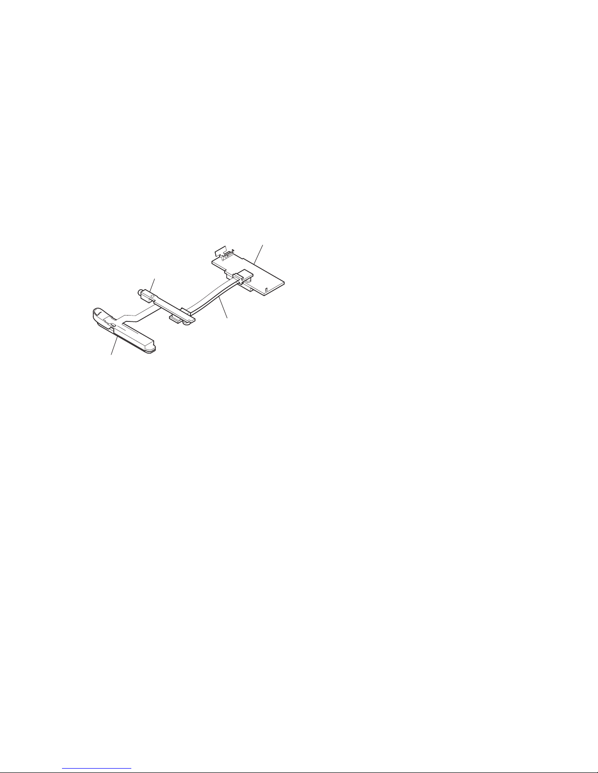
• To check the operation when the MAIN board and SUB board
are removed, check it after connecting CN100 on the MAIN
board and CN200 on the SUB board with the servicing jig (relay
board between the MAIN board and SUB board) as shown below .
SECTION 1
SERVICING NOTES
MAIN board
console unit
SUB board
servicing jig
(MAIN/SUB relay board)
4
NW-MS6
SECTION 2
GENERAL
This section is extracted from
instruction manual.
33
Other Information
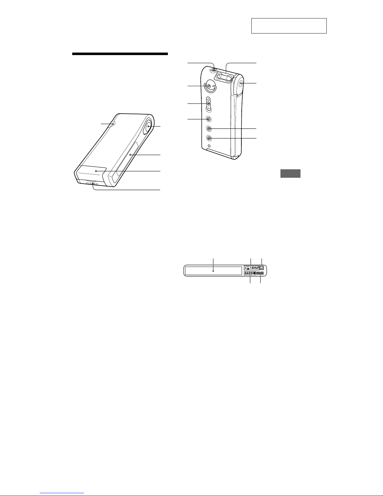
Looking at the
controls
Network Walkman
(front)
1 Access lamp (page 9)
2 Seesaw key (page 11-14, 16-22)
3 Display (page 12, 15)
4 Memory Stick slot (page 9, 11)
5 Battery compartment (page 8)
(rear)
6 i (Headphones/earphones) jack (page 11)
7 Hole for attaching the strap
(The strap is not supplied)
8 HOLD switch (page 16)
9 MEGA BASS/AVLS button (page 14)
0 VOLUME +/– buttons (page 11, 16)
qa Dedicated USB jack (page 9)
qs MENU button (page 13, 16-22)
qd DISPLAY button (page 12, 15)
Display
1 Text/graphic information display
(page 15)
2 Playback mode indication (page 13)
3 AVLS indication (page 14)
4 MEGA BASS indication (page 14)
5 Battery remain indication (page 8)
2
1
3
4
5
6
q;
qa
qs
qd
7
8
9
123
45
NW-MS6
5
• This set can be disassembled in the order shown below.
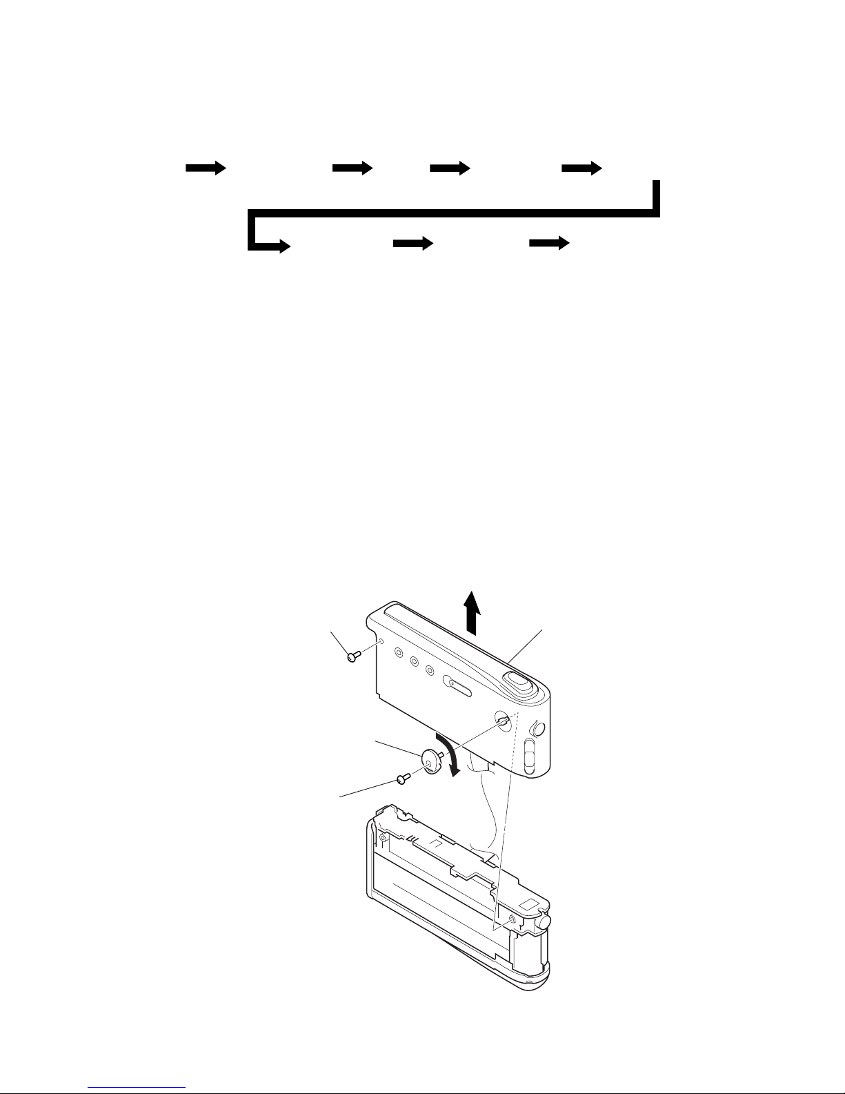
3-1. DISASSEMBLY FLOW
SECTION 3
DISASSEMBLY
Note: Follow the disassembly procedure in the numerical order given.
3-2. CASE BLOCK ASSY
Set
3-2. Case block assy 3-3. Case
3-4. Guide (LED) 3-5. Chassis (main) assy
3-7. Console assy3-6.“Console unit”,
“Sub board”
“Main board”
3-8. Console board
,
1
tapping screw
(M1.4 × 3.5)
3
Remove the strap shaft assy rotating
in the direction of arrow A.
2
tapping screw
(M1.4 × 3.5)
4
case block assy
A
NW-MS6
6
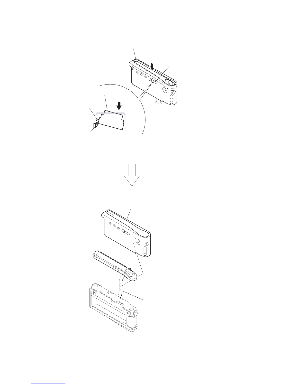
3-3. CASE
3
case
2
Take off the console flexible board
from the case.
Note: Take care not to break
the console flexible board
when taking it off.
1
Inclining the console unit in the direction of arrow,
remove the switch from the knob (hold).
console unit
knob (hold)
knob (hold)
switch
console unit
NW-MS6
7
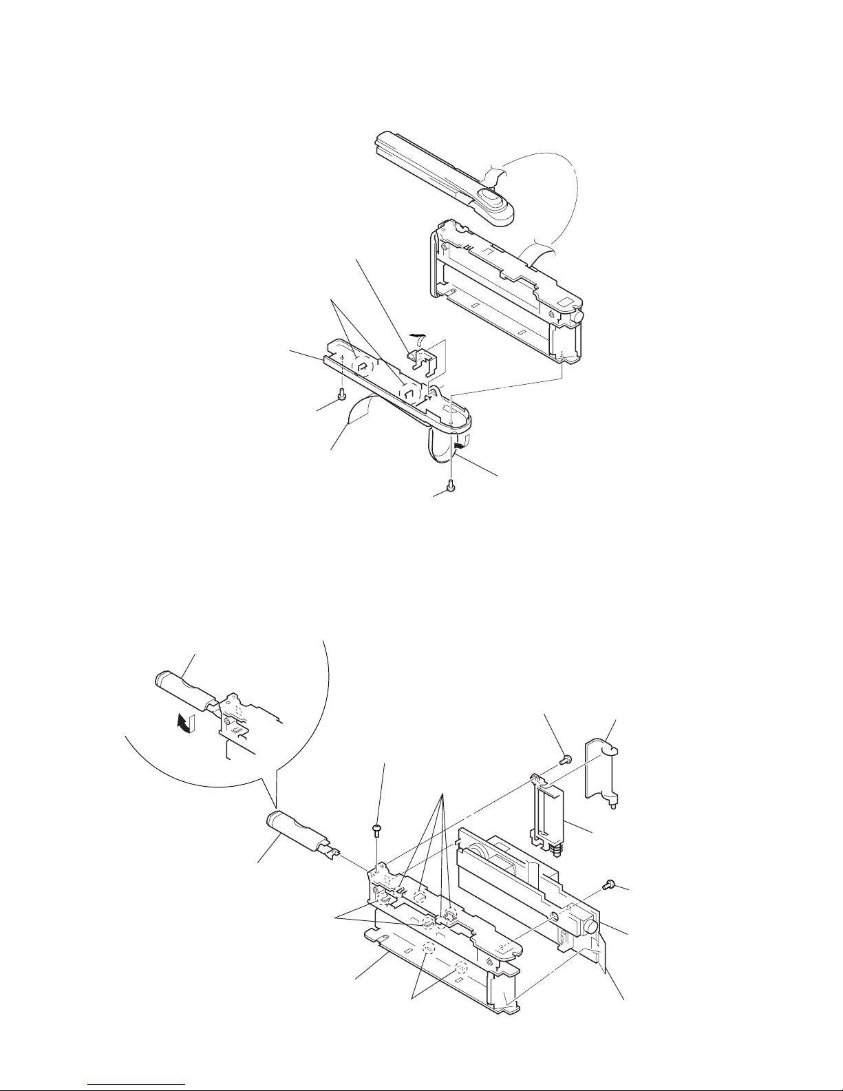
3-4. GUIDE (LED)
3-5. CHASSIS (MAIN) ASSY
3
tapping screw
(M1.4 × 3.5)
q;
MI screw (M1.4)
7
four claws
8
two claws
qa
battery case lid assy
6
two claws
5
tapping screw
(M1.4 × 3.5)
qs
board section
qd
chassis (main) assy
4
guide (eject lid) section
9
Open the battery case lid assy
in the direction of arrow A.
1
Peel off the switch flexible board.
2
lid (eject) assy
A
3
label
2
tapping screw
(M1.4 × 3.5)
4
screw (M1.4)
6
cover (side)
5
two claws
7
Remove the guide (LED)
in the direction of arrow B.
1
Open the lid (PC)
in the direction of arrow A.
A
B
NW-MS6
8
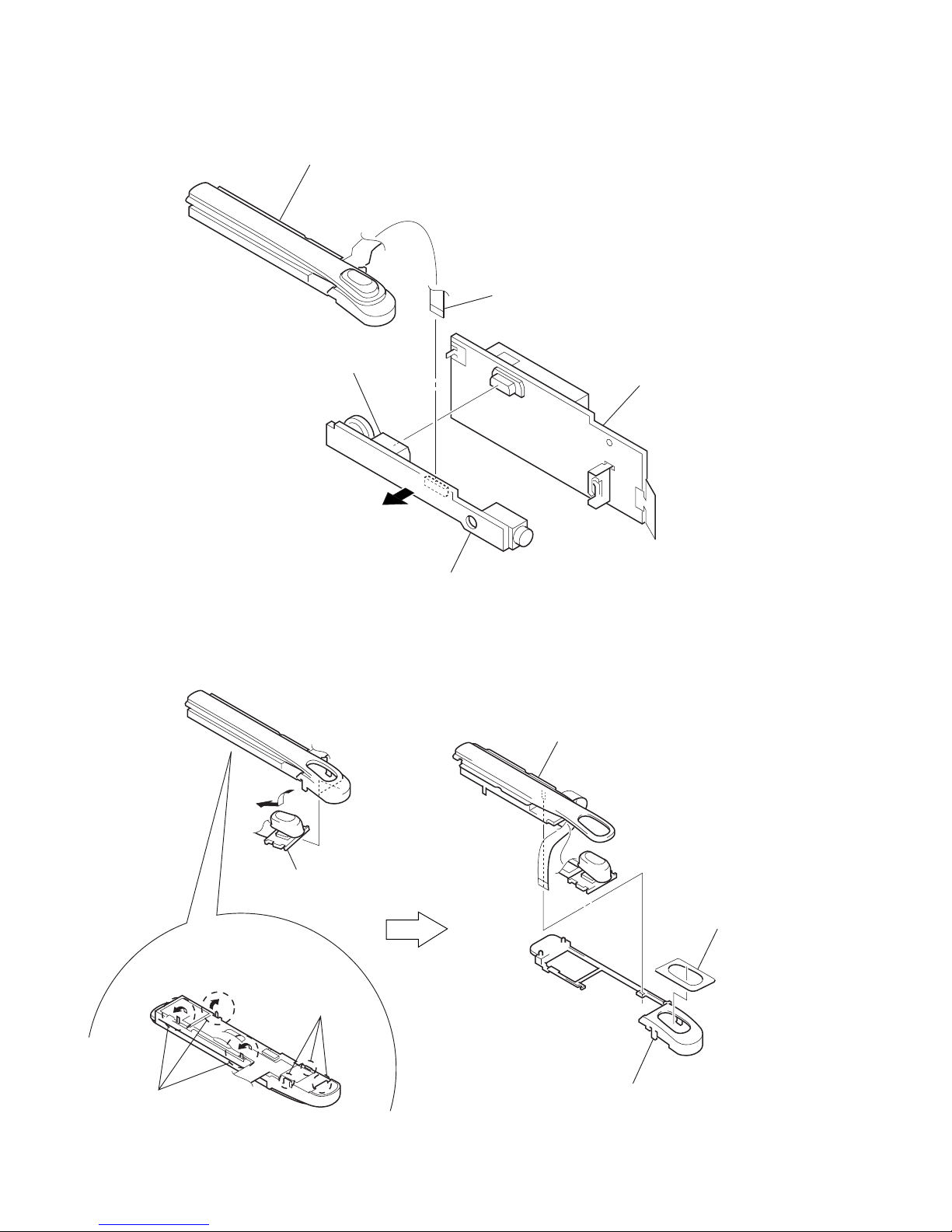
3-6. “CONSOLE UNIT”, “SUB BOARD”, “MAIN BOARD”
3-7. CONSOLE ASSY
4
console unit
1
connector (CN200)
6
MAIN board
3
console flexible board
(CN300)
5
SUB board
2
3
Remove the CONSOLE board
in the direction of arrow A.
Note: Make it sure to use the new adhesive sheet (LCD 1)
when the console assy is installed.
1
Raise up three claws
in the direction of arrow.
2
three claws
4
chassis (LCD)
adhesive sheet (LCD 1
)
5
console assy
A
NW-MS6
9
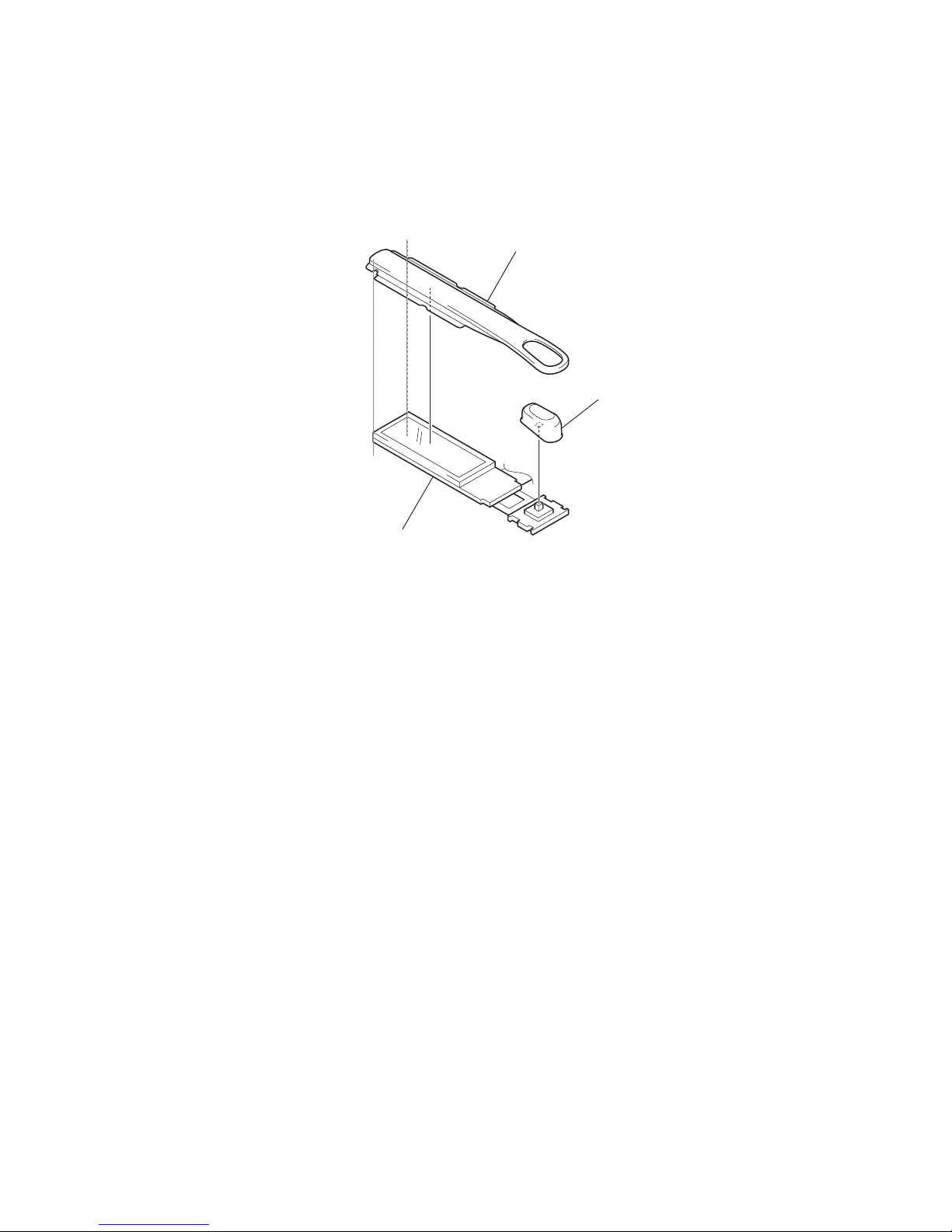
3-8. CONSOLE BOARD
1
window (LCD)
2
button (play
)
3
CONSOLE board
10
NW-MS6
SECTION 4
TEST MODE
[Preparation]
Checking consumed electric current is one of the items to check. Connect an ammeter before setting the test mode.
(Refer to the following figure)
[Setting the Test Mode]
There are following two methods of entering the test mode.
Method 1:
Short the short lands (SL0120) on the MAIN board with a solder bridge, then turn on the power.
Method 2:
Turn on the po wer with the [HOLD] switch OFF. If the set is left as it is, the LCD display becomes on, and after for a while, it changes into
the sleep status (LCD off). Before the status of the display changes into the sleep status, turn ON the [HOLD] switch and press Hs t
[MEGA BASS] t Hs t [VOLUME--] t Hs t [VOLUME+] keys in this order.
[Releasing the Test Mode]
There are following two methods of releasing the test mode.
In case of enter the test mode with the method 1:
Turn off the power and open the solder bridge on the short lands (SL0120) on the MAIN board.
In case of enter the test mode with the method 2:
Turn off the power.
6901 R6902
C8004 C8509 R6903
R5001R5003
C8008
R6018
R6027
R6028
R6035
R6037
C8016
C8014
C
R5002
R9015 C9007
R8103
R9019 R8102
R8607
R8104
R8608
R8105
R8110C8006
1
L9007
IC8000
IC5000
X8000
5643
SL0120
120 119 117 113 109 108 105 102 99 96 93
1 118 116 114 110 107 104 101 98 95 92
3 2 115 112 111 116 103 100 97 94 91
564 82
987 79
12 11 10 76
15 14 13 73
18 17 16 70
20 21 19 67
24 23 22 66
25 26 27 34 37 40 43 46 49 52 61
24 28 32 35 38 41 45 47 50 53 55
30 31 33 36 39 42 44 48 51 54 56
17 25 33 41
18 26 34 42
19 27 35 43
20 28 36 44
21 29 37 45
22 30 38 46
23 31 39 47
24 32 40 48
– MAIN BOARD (Conductor Side) –
battery terminal (+)
battery terminal
(–)
SL0120
+
–
ammeter
1.23Vdc
+
–
regulated dc
power supply
11
NW-MS6
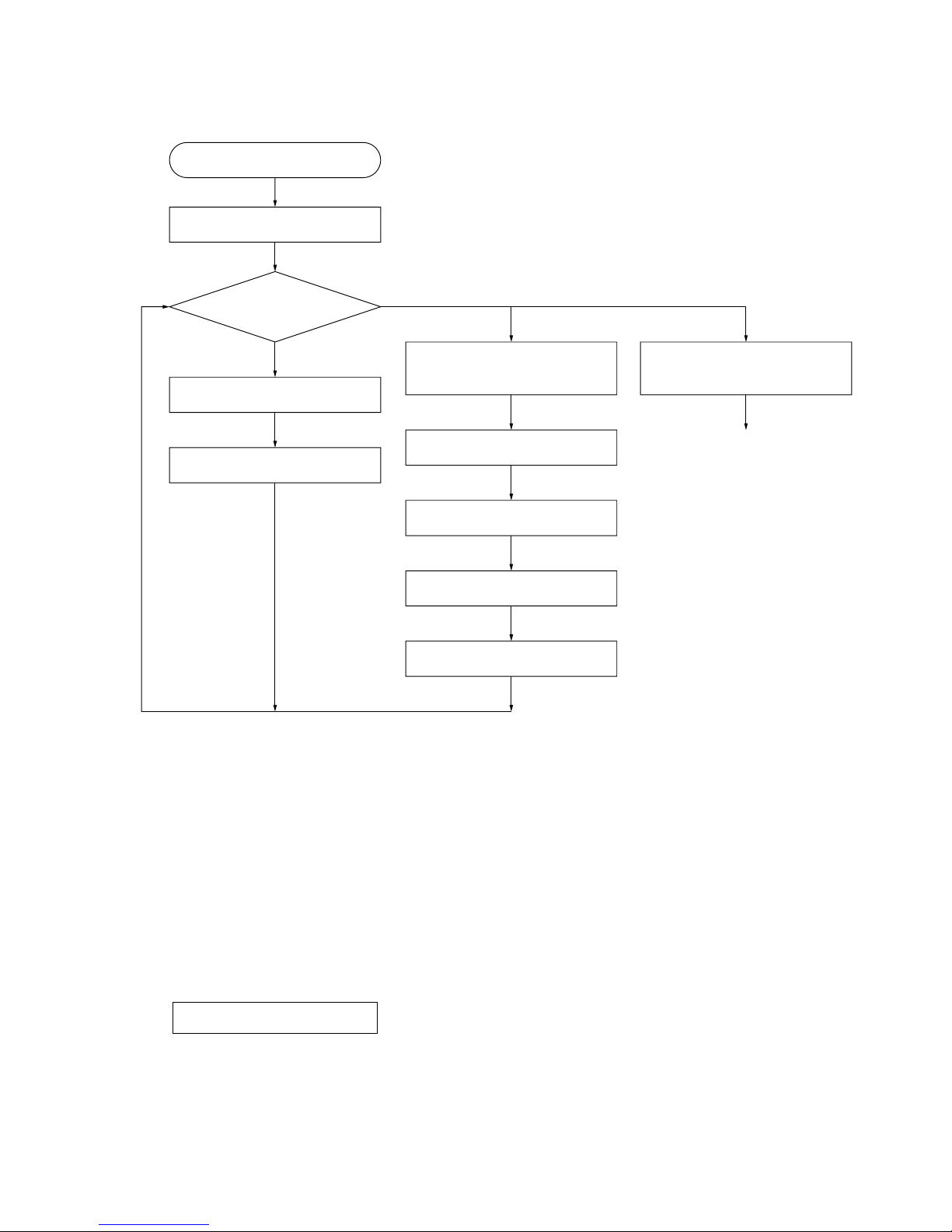
[Flow Chart of Operations in the Test Mode]
[Items to Check in the Test Mode]
1. ROM/RAM Self-check
After entering the test mode, ROM/RAM self-check is performed automatically in the first place. By entering the test mode with ke y input,
however, no RAM check is performed.
1 Result of the ROM/RAM check is OK:
The LCD back light turns on, and version and destination is displayed automatically.
2 Result of the ROM check is NG:
“BAD ROM” is displayed on the LCD, and the LCD back light keeps blinking.
3 Result of the RAM check is NG:
Nothing is displayed on the LCD, and the LCD back light keeps blinking
2. Display of Version and Destination
Version and destination are displayed as follows.
Every time the [DISPLAY] key is pressed, the display changes as “version and destination t LCD all lit t LCD all off t version and
destination...”.
Also, pressing the [VOLUME+] key changes the mode to writing destination, and if pressing the [VOLUME--] key, the unit goes into the
sleep mode.
Enter the test mode
1. ROM/RAM Self-check
2. Display of version
and destination
3. Writing destination
(Checking voltage and
consumed electric current)
4. Checking the rated
voltage
5. Checking the LOW BATT
voltage
6. USB self-check
7. RTC self-check
8. Sleep mode
(Checking consumed electric current)
Waking up with the normal mode
(Waking up with the test mode, if
the short lands (SL0120) have
been short)
[DISPLAY]
key
[DISPLAY]
key
[DISPLAY]
key
[MENU]
key
[MENU]
key
[MENU]
key
[MENU]
key
[MENU]
key
[VOLUME+]
key
[VOLUME--]
key
LCD all off
LCD all lit
any key
v1.00.03JP
display example
12
NW-MS6
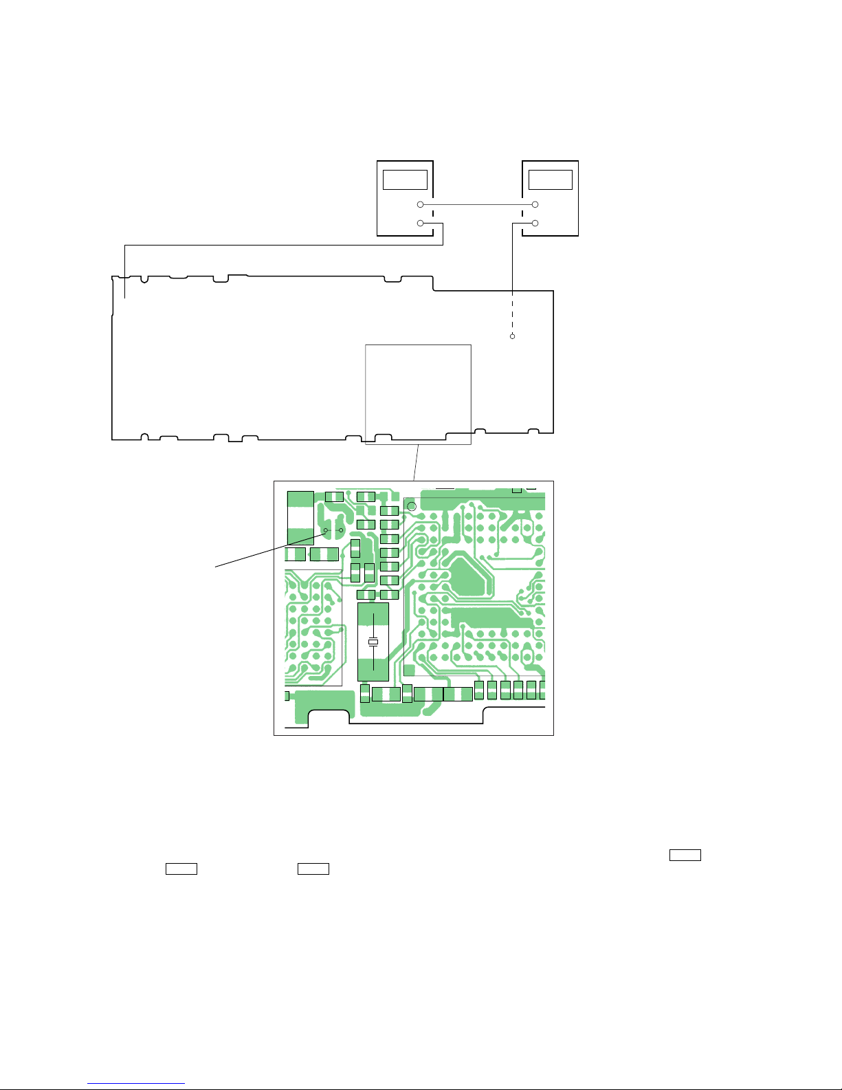
3. Writing Destination (Checking Voltage and Consumed Electric Current)
After entering this mode, display of version and destination blinks. (The LCD back light turns off)
3-1. Checking voltage and consumed electric current
Note: Perform checking voltage and consumed electric current with the LCD back light off.
Specified value :
VDDCORE voltage : 1.8 to 2.0 V (voltage between TP9002 (VDDCORE) and TP (GND))
VDDIO2 voltage : 2.7 to 2.9 V (voltage between TP9003 (VDDIO2) and TP (GND))
Consumed electric current : below 200 mA
Connecting Location:
3-2. Writing destination
Note: When the displayed destination is correct, writing destination is no needed. But when the EEPROM check is performed, leav e the display as it is and
press the [DISPLAY] key to perform this check.
After replacing the EEPROM, make it sure to write destination.
Every time the [MEGA BASS] key is pressed, the display changes as t “JP t US t EU t X t JP t...”.
Select the destination*, and press the [DISPLAY] key to fix. Then the LCD display changes from blinking to being on. Also at the same
time, checking destination written on the EEPROM is performed, and when the result is OK, the LCD back light turns on, and if not, starts
blinking.
*) JP : Japanese model EU : AEP, UK, E, Hong Kong, Korean, Chinese models
US : US model X : French model
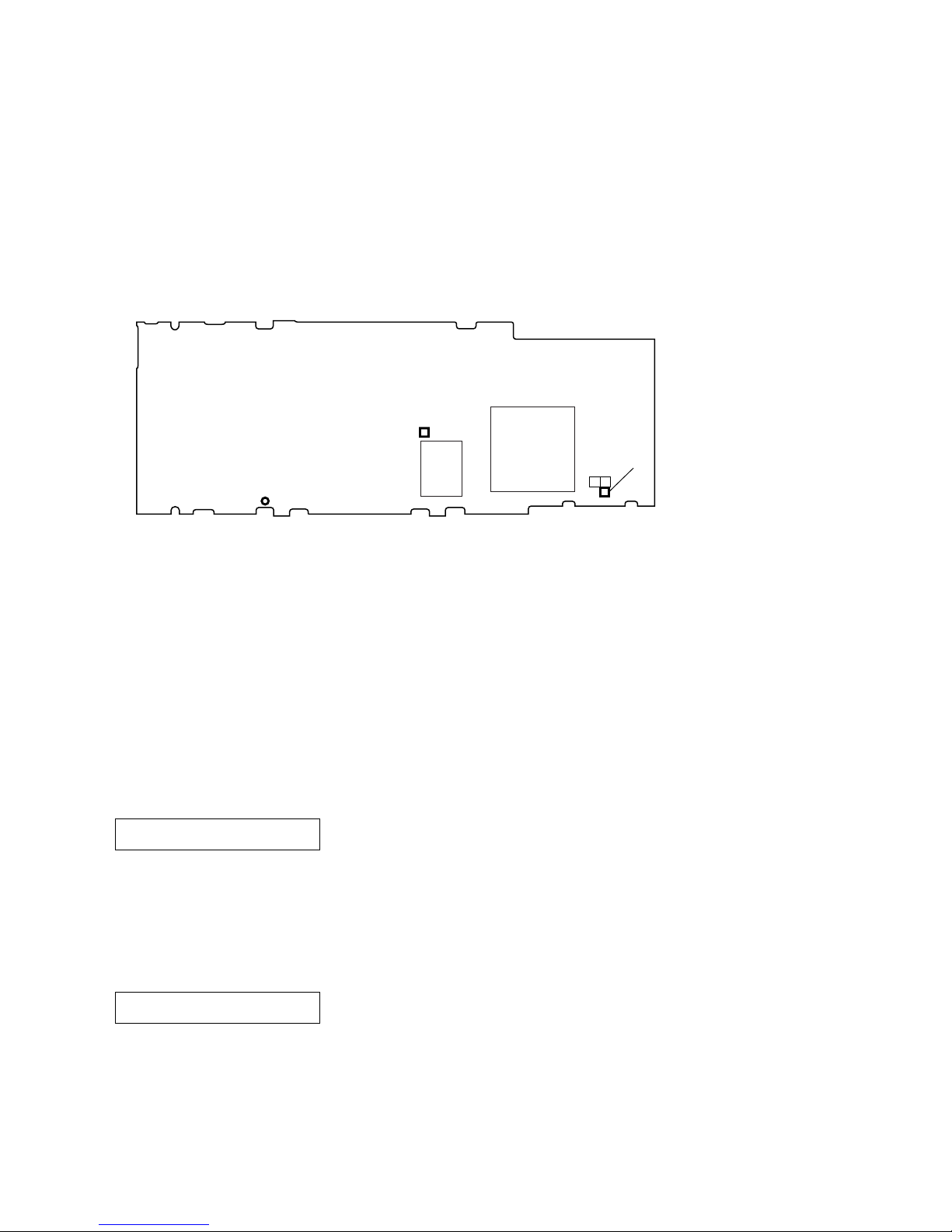
4. Checking the Rated Voltage
Note: Before entering this mode, check that the input voltage is the specified value (1.23 V).
Press the [MENU] key after “3-2. Writing Destination” to enter this mode. The check is started automatically.
When the result is OK, “1. HLFBT >OK” is displayed on the LCD. And if the result is NG, “1. HLFBT >NG” is displayed.
5. Checking LOW BATT Voltage
Note: Before entering this mode, adjust the input voltage to the LOW BATT voltage value (0.95 V).
Press the [MENU] key after “4. Checking the rated voltage” to enter this mode. The check is started automatically.
When the result is OK, “2. LOWBT >OK” is displayed on the LCD. And if the result is NG, “2. LOWBT >NG” is displayed.
Press the [MENU] key to go to the next USB self-check.
TP9003
(VDDIO2)
IC8000
IC5000
TP9002
(VDDCORE)
TP (GND)
– MAIN BOARD (Conductor Side) –
1.HLFBT >
display
2.LOWBT >
display

13
NW-MS6
6. USB Self-check
The indication is displayed as below after entering this mode.
This mode is not used in servicing.
Press the [MENU] key to go to the next RTC self-check.
7. RTC Self-check
The indication is displayed as below after entering this mode.
The check on writing/reading real time clock is performed automatically and when the result is OK, “4. RTC >OK” is displayed on the
LCD and LCD back light turns on. If the result is NG, “4. RTC >NG” is displayed and the LCD back light blinks.
Press the [MENU] key to go back to “2. Display of Version and Destination”.
8. Sleep Mode (Checking Consumed Electric Current)
When the [VOLUME--] key is pressed at “2. Display of Version and Destination”, the unit goes into sleep mode.
Once entering this mode, the LCD turns off and the unit goes into the sleep (standby) status. After being into the sleep status, check that
consumed electric current is within the specified value.
Specified value : below 1 mA
The unit is waked up with normal mode with pressing any key. If the short lands (SL0120)) has been short, however, waked up and enters
this test mode again.
3.USB >
display
4.RTC >
display

14
NW-MS6
MEMO
 Loading...