

Sony Walkman MZ-R900 Service Manual
SERVICE MANUAL
Audio playing system
MiniDisc digital audio system
Laser diode properties
Material: GaAlAs
Wavelength:
λ = 790 nm
Emission duration: continuous
Laser output: less than 44.6 µW
(This output is th e value measured at a d istance
of 200 mm from the lens surface on the optical
pick-up block with 7 mm aperture.)
Recording and playback time
When using MDW-80:
Maximum 160 min. in monaural
Maximum 320 min. in stereo
Revolutions
350 rpm to 2,800 rpm (CLV)
Error correction
ACIRC (Advanced Cross Interleave Reed
Solomon Code)
Sampling frequency
44.1 kHz
Sampling rate converter
Input: 32 kHz/44.1 kHz/48 kHz
Coding
ATRAC (Adaptive TRansform Acoustic
Coding)
ATRAC 3 — L P 2
ATRAC 3 — L P 4
Modulation system
EFM (Eight to Fourteen Modulation)
Number of channels
2 stereo channels
1 monaural channel
Wow and Flutter
Below measurable limit
Inputs
Microphone: stereo mini-jack, minimum input
level 0.25 mV
Line in
1)
: stereo mini-jack, mini mum input
level 49 mV
Optical (Digita l) in
1)
: optical (digital) mini-jack
Outputs
i/LINE OUT2): stereo mini-jack
headphones/earphones: max im um out put
level 5 mW + 5 mW, load impedance 16 ohm
LINE OUT: 194 mV, load impedance 10
kilohm
1)
The LINE IN (OPT) jack is used to connect
either a digital (optical) cable or a line
(analog) cable.
2)
The i/LINE OUT jack connects either
headphones/earphones or a line cab le.
Power requirements
Sony AC Power Adaptor connected at th e D C
IN 3V jack:
230–240 V AC, 50/60 Hz (UK and Hong
Kong model)
220–230 V AC, 50/60 Hz (European model)
120 V AC, 50 Hz (Canadian model)
240 V AC, 50 Hz (Australian model)
220 V AC, 50 Hz (Chinese model)
110/220 V AC, 60 Hz (Korean model)
100–240 V AC, 50/60 Hz (Other models)
Nickel metal hydride rechargeable battery NH14WM
LR6 (size AA) alkaline batt ery
Battery operation time
Battery life
1)
When recording
2)
(Unit: approx.hours)(EIAJ3))
1)
The batter y life may be shorte r du e to
operating conditions and the tempera tur e of
the location.
2)
When you record, use a fully charge d
rechargeable batter y. Reco rd ing time may
differ according to the alkaline batteries .
Batteries Stereo LP2 LP4
NH-14WM
nickel metal
hydride
rechargeable
battery
4)
8 10.5 13
LR6 (SG)
Sony alkaline
dry battery
5)
71014
NH-14WM
nickel metal
hydride
rechargeable
battery
4)
+ One LR6
(SG)
5)
19 26 30
Frequency response
20 to 20,000 Hz ± 3 dB
120 V AC, 60 Hz (US model)
PORTABLE MINIDISC RECORDER
US Model
Canadian Model
AEP Model
UK Model
E Model
Australian Model
Chinese Model
Tourist Model
SPECIFICATIONS
MZ-R900
US and foreign patents licensed from Dolby
Laboratories Licensing Corporation.
Photo: Red type
– Continued on next page –
Model Name Using Similar Mechanism NEW
Mechanism Type MT-MZR900-171
Optical Pick-up Name LCX-4R
9-927-991-13 Sony Corporation
2001C0500-1 Audio Entertainment Group
C 2001.3 General Engineering Dept.
Ver 1.2 2001. 03
2
MZ-R900
TABLE OF CONTENTS
1. SERVICING NOTES ............................................... 3
2. GENERAL ................................................................... 4
3. DISASSEMBLY
3-1. Disassembly Flow........................................................... 5
3-2. Panel Assy , Bottom ......................................................... 5
3-3. Panel Assy, Upper Section .............................................. 6
3-4. “LCD Module”, “Panel Assy, Upper” ............................ 6
3-5. MAIN Board Assy .......................................................... 7
3-6. “Case Assy, Battery”, “MAIN Board” ........................... 7
3-7. Strip, Ornamental............................................................ 8
3-8. “MD Mechanism Deck (MT-MZR900-171)”,
“Chassis Assy, Set” ......................................................... 8
3-9. Service Assy, OP (LCX-4R) ........................................... 9
3-10. Holder Assy ..................................................................... 10
3-11. MOTOR FLEXIBLE Board............................................ 10
3-12. Motor, DC (Sled) (M602) ............................................... 11
3-13. “Motor, DC (Spindle) (M601)”,
“Motor, DC (Over Write Head UP/DOWN) (M603) ..... 11
4. TEST MODE.............................................................. 12
5. ELECTRICAL ADJUSTMENTS......................... 17
6. DIAGRAMS
6-1. Block Diagram –SERVO Section– ................................. 27
6-2. Block Diagram –AUDIO Section– ................................. 28
6-3. Block Diagram –KEY CONTROL/DISPLAY/
POWER SUPPLY Section– ............................................ 29
6-4. Printed W iring Boards..................................................... 30
6-5. Schematic Diagram......................................................... 31
6-6. IC Pin Function Description ........................................... 33
7. EXPLODED VIEWS
7-1. Panel Section................................................................... 39
7-2. Chassis Section ............................................................... 40
7-3. MD Mechanism Deck Section (MT-MZR900-171) ....... 41
8. ELECTRICAL PARTS LIST ............................... 42
SAFETY-RELATED COMPONENT WARNING!!
COMPONENTS IDENTIFIED BY MARK 0 OR DOTTED
LINE WITH MARK 0 ON THE SCHEMATIC DIAGRAMS
AND IN THE PARTS LIST ARE CRITICAL TO SAFE
OPERATION. REPLACE THESE COMPONENTS WITH
SONY PARTS WHOSE PART NUMBERS APPEAR AS
SHOWN IN THIS MANUAL OR IN SUPPLEMENTS PUBLISHED BY SONY.
Dimensions
Approx. 78.9 × 17.1 × 72.0 mm (w/h/d)
(3
1
/8 × 11/16 × 27/8 in.)
Mass
Approx. 110 g (3.9 oz) the recorder only
Supplied accessories
AC power adaptor (1)
Headphones/earphones with a remote co ntr ol
(1)
Rechargeable bat tery (1)
Dry battery case (1)
Rechargeable bat tery carrying case (1)
Carrying pouch/carrying case with a belt clip
AC plug adaptor (World model only) (1)
Optical cable (1)
Design and specifications are subject to change
without notice.
1)
Measured in accordance with the
EIAJ(Electronic Industries Asso ci ation of
Japan) standard.
2)
When using a 100% fully charged
rechargeable battery.
3)
When using a Sony LR6 (SG) “STAMINA”
alkaline dry battery (produced in Japa n) .
On power sources
• For use in your house: Use the AC power adaptor
supplied with this recorder. Do not use any other
AC power adaptor since i t may c ause the recorder
to malfunction.
Polarity of the
plug
4)
When using a 100% fully charged
rechargeable battery.
5)
When using a Sony LR6 (SG) “STAMINA”
alkaline dry battery (produced in Japa n).
When playing
(Unit: approx.hours)(EIAJ1))
Batteries Stereo LP2 LP4
NH-14WM
nickel metal
hydride
rechargeable
battery
2)
21 23 26
LR6 (SG)
Sony alkaline
dry battery
3)
30 35 38
NH-14WM
nickel metal
hydride
rechargeable
battery
2)
+ One LR6
(SG)
3)
53 60 66
3)
Measured in accordance with the
EIAJ(Electronic Industries Associ at ion of
Japan) standard.
(except U.S.A model) (1)
ATTENTION AU COMPOSANT AYANT RAPPORT
À LA SÉCURITÉ!
LES COMPOSANTS IDENTIFIÉS P AR UNE MARQUE 0
SUR LES DIAGRAMMES SCHÉMA TIQUES ET LA LISTE
DES PIÈCES SONT CRITIQUES POUR LA SÉCURITÉ
DE FONCTIONNEMENT. NE REMPLACER CES COMPOSANTS QUE PAR DES PIÈCES SONY DONT LES
NUMÉROS SONT DONNÉS DANS CE MANUEL OU
DANS LES SUPPLÉMENTS PUBLIÉS PAR SONY.
3
MZ-R900
NOTES ON HANDLING THE OPTICAL PICK-UP
BLOCK OR BASE UNIT
The laser diode in the optical pick-up block may suffer electrostatic break-down because of the potential difference generated
by the charged electrostatic load, etc. on clothing and the human
body.
During repair, pay attention to electrostatic break-down and also
use the procedure in the printed matter which is included in the
repair parts.
The flexible board is easily damaged and should be handled with
care.
NOTES ON LASER DIODE EMISSION CHECK
Never look into the laser diode emission from right above when
checking it for adjustment. It is feared that you will lose your sight.
NOTES ON HANDLING THE OPTICAL PICK-UP BLOCK
(LCX-4R)
The laser diode in the optical pick-up block may suffer electrostatic break-down easily. When handling it, perform soldering
bridge to the laser-tap on the flexible board. Also perform measures against electrostatic break-down sufficiently before the operation. The flexible board is easily damaged and should be handled
with care.
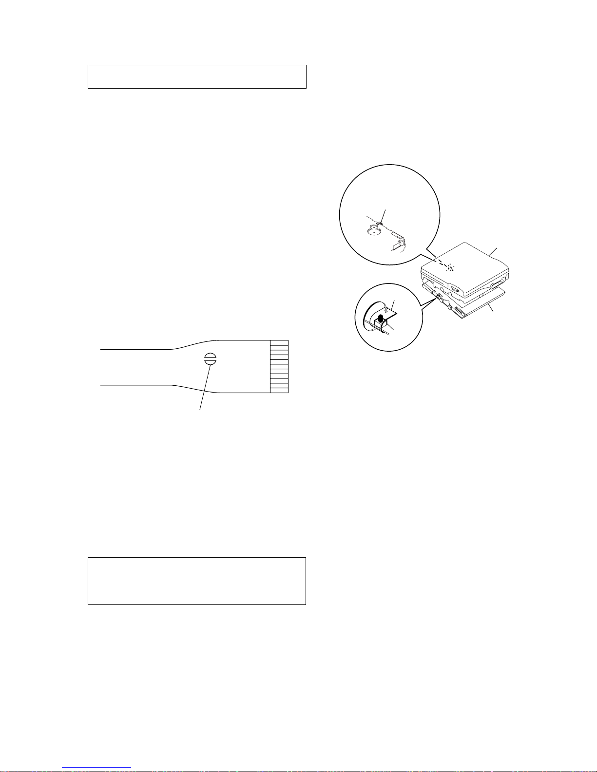
OPTICAL PICK-UP FLEXIBLE BOARD
SECTION 1
SERVICING NOTES
• In performing the repair with the power supplied to the set,
removing the MAIN board causes the set to be disabled.
In such a case, fix a conve x part of the open/close detect switch
(S806 on MAIN board) with a tape in advance.
Handle the FLEXIBLE board (overwrite head) with care, as it
has been soldered directly to the MAIN board.
In repairing the component side of MAIN board, connect the
FLEXIBLE board (overwrite head) and the MAIN board with
the lead wires in advance. (See page 7)
laser-tap
upper panel assy
MAIN board
Tape
S806
FLEXIBLE board
(Over write head)
• Replacement of CDX2671-203GA (IC801) used in this set
requires a special tool.
• On the set having the microcomputer version 1.000, some
adjusted values were set in the manual mode at the shipment,
but these data will be cleared when the NV is reset. Therefore,
on the set having the microcomputer version 1.000, change the
adjusted values following the Change of Adjusted Values
immediately after the NV was reset. (See page 17)
• If the nonvolatile memory was replaced on the set, the modified
program data must be written to the nonvolatile memory . In such
a case, write the modified data that meets the microcomputer
version following the patch data rewriting procedure at the
replacement of nonvolatile memory. (See page 22)
Notes on chip component replacement
• Never reuse a disconnected chip component.
• Notice that the minus side of a tantalum capacitor may be damaged by heat.
Flexible Circuit Board Repairing
• Keep the temperature of the soldering iron around 270 ˚C during repairing.
• Do not touch the soldering iron on the same conductor of the
circuit board (within 3 times).
• Be careful not to apply force on the conductor when soldering
or unsoldering.
CAUTION
Use of controls or adjustments or performance of procedures
other than those specified herein may result in hazardous radiation exposure.
4
MZ-R900
SECTION 2
GENERAL
This section is extracted from
instruction manual.
8
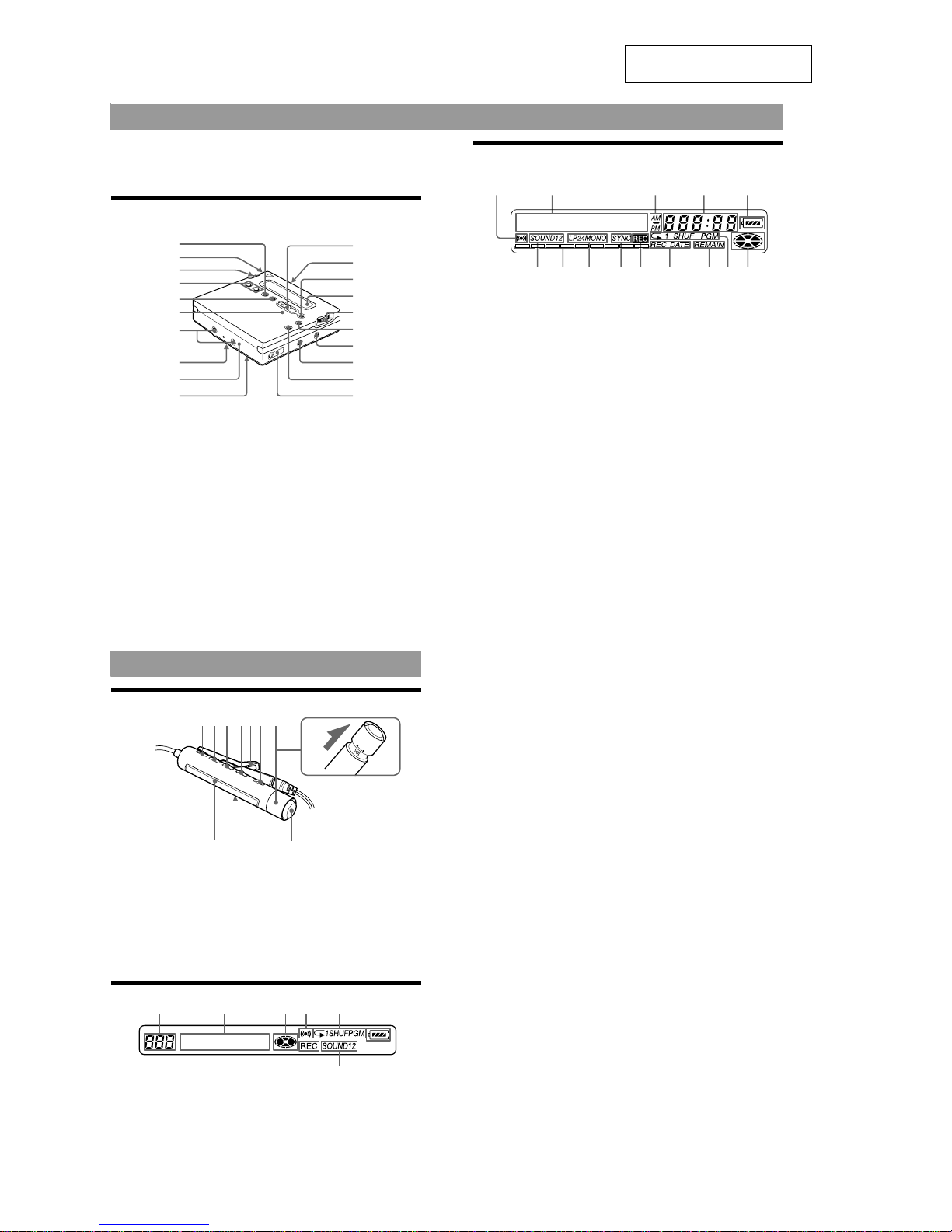
Looking at controls
See pages in ( ) for more details.
The recorder
A END SEARCH button (17) (47)
B Battery compartment (13)
C Jog lever (L) (ME N U/ENTER) (11)
(20) (25) (34) (43) (53)
D VOL +/– button (19) (47)
E REC MODE button (23)
F REC indicator (29)
G Terminals for attaching dry battery
case (14)
H SYNCHRO REC ON/OFF (synchro-
recording) switch (at the rear) (24)
I DC IN 3V jack (13) (16)
J HOLD switch (at the rear) (14) (55)
K REC (record) swi tch (17) (25)
L OPEN button (15)
M X (pause) button (17) (19) (27) (31)
(44) (47) (51)
N Display window (24) (34) (53)
O Jog lever (R) (N, . />) (12)
(17) (19) (44) (47)
P x (stop)/CHARGE button (13) (17)
(19) (23) (43)
Q LINE IN (OPT) jack (16) (22)
R MIC (PLUG IN POWER) jack (25)
S T MARK button (44)
T i (headphone s/ earphones)/LINE
OUT jack (14) (31) (41 )
1
2
3
4
5
q;
6
7
ql
w;
qk
qj
qh
qg
qf
qd
qs
qa
9
8
9
The display window of the recorder
A Alarm indication (53)
B Character information display (29)
(34)
Displays the disc and track names,
date, error messages, track numbers,
etc.
C AM/PM ind ication (30)
Lights up along with the time
indication in the 12-hour system.
D Time display (29) (40)
Shows the recorded time, current
time, elapsed time of the track or M D
being recorded or played .
E Battery indication (13)
Shows approximate battery condition.
F Sound indication (36)
Lights up when Digital Sound Preset
is on.
G Level meter (28)
Shows the volume of the MD being
played or recorded.
H LP2, LP4, MONO (monaural)
indication (23)
I SYNC (synchro-recording) indication
(24)
Lights up while synchro-recording.
J REC indication (17)
Lights up while recording. When
flashing, the recorder is in record
standby mode.
K REC DATE (recorded/current date)
indication (40)
Lights up along with the date and time
the MD was recorded . When only
“DATE” lights up, the current date
and time are display ed.
L REMAIN (remaining time/tracks)
indication (28) (40)
Lights up along with the remain in g
time of the track, the remaining time
of the MD, or the remaining number
of tracks.
M Play mode indication (34)
Shows the play mode of the MD.
N Disc indication (24) (34)
Shows that the disc is rotating for
recording, playing or editing an MD.
12 345
6 7 8 9 q; qa qs qd qf
10
The headphones/earphones with a remote control
A DISPLAY button (29) (38) (46) (48)
(53)
B PLAYMODE button (35) (48)
C RPT/ENT (repeat/enter) b ut ton (36)
(37)
D SOUND button (36)
E Clip
F X (pause) button (19) (48) (51)
G Control (./N>) (12) (19)
(36) (46) (48) (51) (53)
N> : play, AMS, FF
. : REW
H Control (VOL +/–) (12) (19) (48)
Pull and turn to adjust the volume.
I Display window (29) (36)
J HOLD switch (14) (55)
K x (stop) button (19) (38) (46) (53)
The display window of the remote control
A Track number display (2 9) (36) (54)
B Character information display (29)
(36) (54)
C Disc indication (29) (36) (54)
D Alarm indicatio n (54)
E Play mode indic at io n (36)
F Battery indication (29) (36) (54)
G REC indication (17) (29)
H SOUND indication (36)
+
–
A B C DE
K
F
G
IJ
H
F
HG
A
BCDE

5
MZ-R900
• This set can be disassembled in the order shown below.
3-1. DISASSEMBLY FLOW
SECTION 3
DISASSEMBLY
Note: Follow the disassembly procedure in the numerical order given.
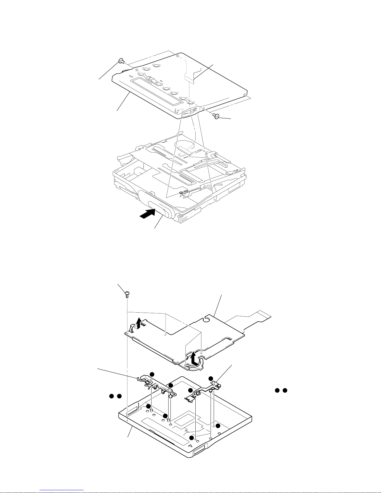
3-2. PANEL ASSY, BOTTOM
3-2. PANEL ASSY,
BOTTOM
3-3. PANEL ASSY,
UPPER SECTION
SET
3-4. “LCD MODULE”,
“PANEL ASSY, UPPER”
3-6. “CASE ASSY, BATTERY”,
“MAIN BOARD”
3-8. “MD MECHANISM DECK
(MT-MZR900-171)”,
“CHASSIS ASSY, SET”
3-7. STRIP,
ORNAMENTAL
3-5. MAIN BOARD ASSY
3-9. SERVICE ASSY, OP
(LCX-4R)
3-10. HOLDER ASSY
3-11. MOTOR FLEXIBLE BOARD
3-12. MOTOR, DC (SLED) (M602)
3-13. “MOTOR, DC (SPINDLE) (M601)”,
“MOTOR, DC (OVER WRITE HEAD UP/DOWN)
(M603)”
5
two screws
(1.4)
6
Remove the “panel assy, bottom”
in the direction of arrow
A
.
5
screw (1.4)
5
two screws
(1.4)
4
Close the
battery terminal (plus).
1
Open the
lid, battery case.
3
lid, battery case
S802
S801
2
claw
A
knob (hold)
Note: On installation,
adjust the position of
both two switches (S801, S802)
and two knobs (hold).
6
MZ-R900
3-3. PANEL ASSY, UPPER SECTION
3-4. “LCD MODULE”, “PANEL ASSY, UPPER”
3
two screws
(1.4)
4
panel assy, upper section
2
Push button (open).
3
two screw
s
(1.4)
1
flexible board
(CN801)
1
four screws (1.7)
3
button (A), control
Note: On installation,
adjust the hole of
“button (A), control”
and boss of “panel assy,
upper”. (in the fig. , )
4
button (B), control
Note: On installation,
adjust the boss of
“button (B), control” and
hole of “panel assy, upper”.
(in the fig. , )
5
panel assy, upper
2
LCD module
a
b
a
a
b
b
c
c
d
d
d
c
7
MZ-R900
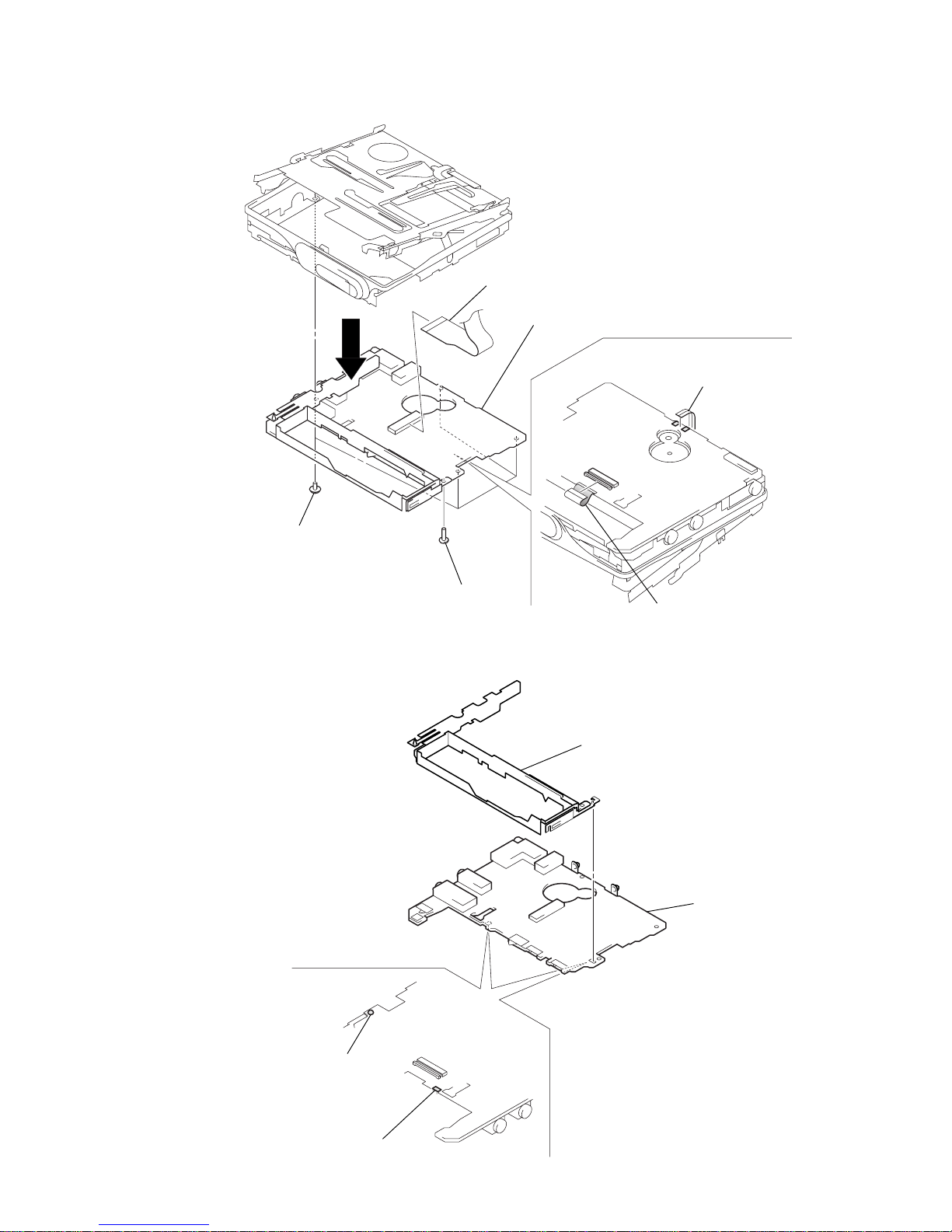
3-5. MAIN BOARD ASSY
3-6. “CASE ASSY, BATTERY”, “MAIN BOARD”
3
four screws
(M1.4 toothed lock)
4
screw
(1.4)
2
flexible board
(CN502)
1
Remove two solder
s
of flexible board.
6
flexible board
(CN501)
5
7
main board assy
2
case assy, battery
3
main board
1
Remove the solder
of terminal (minus).
1
Remove the solder
of terminal (plus).
8
MZ-R900
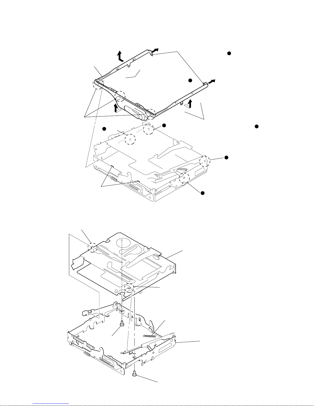
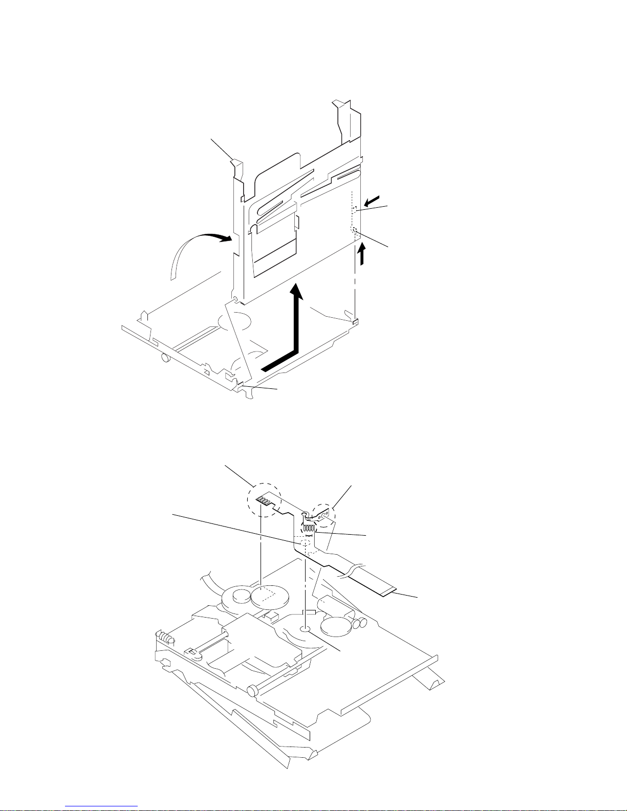
3-7. STRIP, ORNAMENTAL
3-8. “MD MECHANISM DECK (MT-MZR900-171)”, “CHASSIS ASSY, SET”
)
)
)
)
@
@
4
two convex portions
pointed with
@
3
three bosses
5
Remove the “strip, ornamental”
in the direction of arrow
C
.
2
Open toward the direction
B
to disengage two bosses
and convex portions pointed
with
*
.
2
Open toward the direction
B
to disengage two bosses
and convex portions pointed
with
*
.
1
Pull toward the direction
A
to disengage two bosses .
A
A
B
B
C
boss
boss
boss
boss
Note: As the “strip, ornamental”
is very fragile, do not
give an excessive force
to the entire assy when
removing it.
a
a
a
b
b
b
b
2
boss
2
boss
3
MD mechanism deck
(MT-MZR900-171)
1
screw
(1.4)
1
screw (1.4)
5
chassis assy, se
t
4
spring (arm), tension
9
MZ-R900
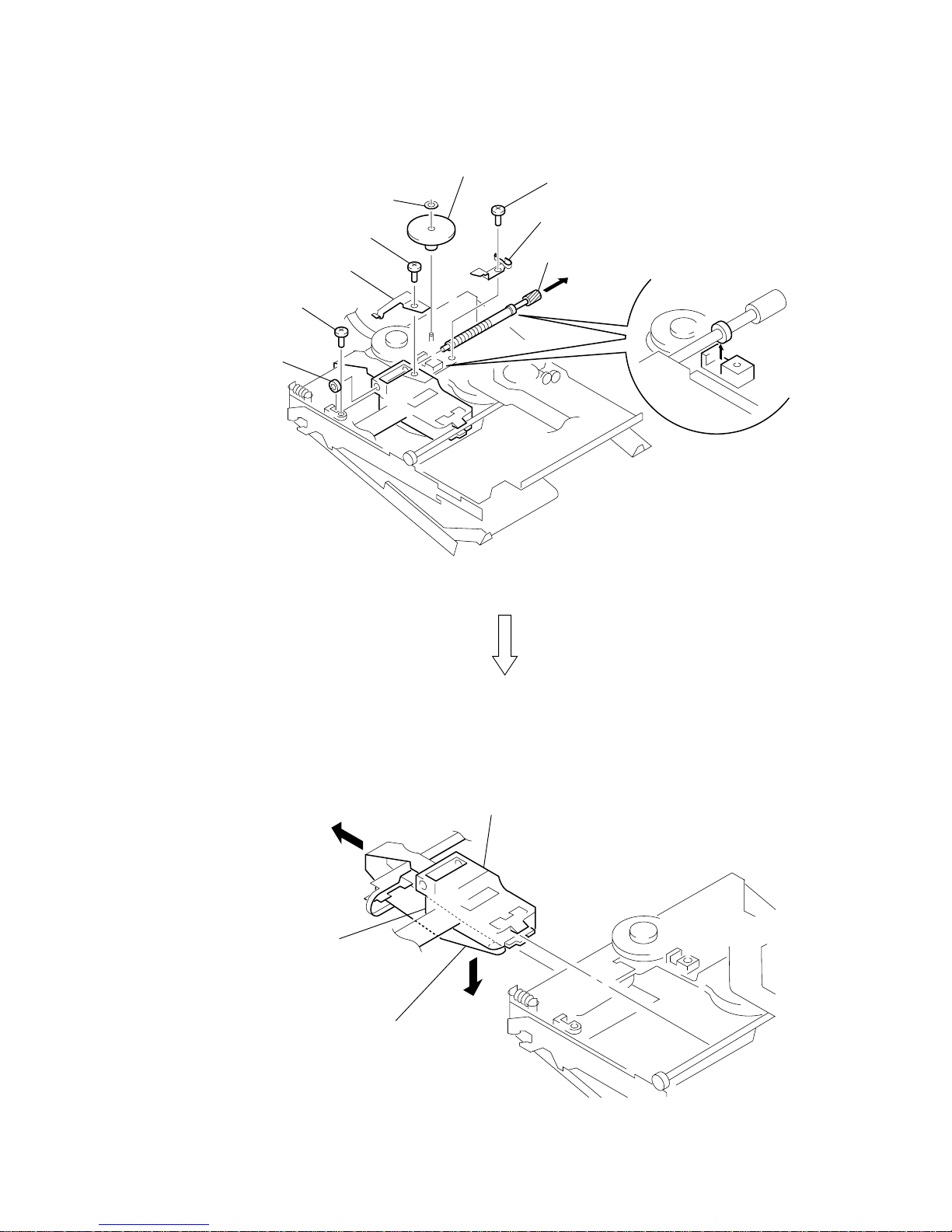
3-9. SERVICE ASSY, OP (LCX-4R)
0
bearing (N)
5
screw
4
spring (S), rack
3
screw (M1.4)
1
washer (0.8-2.5)
2
gear (SA)
6
screw (M1.4)
7
spring, thrust
9
Pull off “screw, lead”
8
over write head section
service assy, OP (LCX-4R)
qa
Opening the over write head
toward the direction
A
, remove the “service assy, OP
(LCX-4R) toward the direction
B
.
A
B
Note: Do not open the entire assy forcibly,
when opening the over write head.
10
MZ-R900
3-10. HOLDER ASSY
3-11. MOTOR FLEXIBLE BOARD
2
Push the convex portion
toward the direction
B
and
open the holder assy toward
the direction
A
to erect uprightly.
3
Remove the concave portion
in the direction of arrow
C
.
5
Remove the holder assy in the
direction of arrow
D
.
D
C
B
A
1
Open the holder assy.
4
boss
1
Remove four solders of
“motor, DC (sled) (M602)”.
1
Remove four solders of
“motor, DC (spindle) (M601)”.
3
motor flexible board
DC motor (sled)
circular hole
1
Remove two solders of
DC motor (over write head up/down) (M603).
2
adhesive sheet
Note: Align a circular hole in the
stripping paper with a circular hole
in the “motor, DC (sled)”,
when mounting the motor
flexible board.
11
MZ-R900
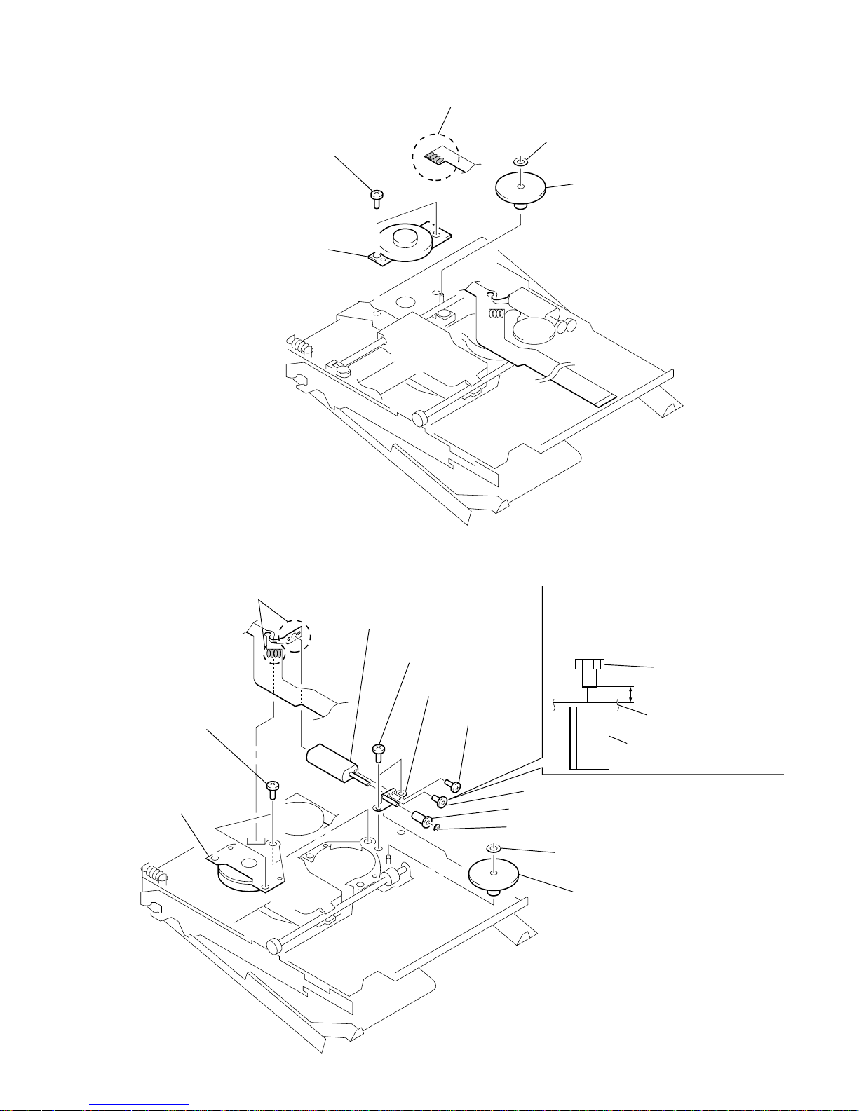
5
motor, DC
(spindle) (M601)
4
three screws
(M1.4)
1
Remove six solders of
motor flexible board.
qa
motor, DC (over write head up/down)
(M603)
6
two screws (M1.4)
qs
chassis assy, gear
9
screw (M1.2)
0
gear (HA)
gear (HA)
chassis assy, gear
2.65 mm
motor, DC (over write head
up/down) (M603)
8
gear (HB)
7
washer (0.8-2.5)
2
washer (0.8-2.5)
3
gear (HC)
Note: Press-fit the gear (HA) up to the
position of the “motor, DC (over
write head up/down) (M603) as shown
below.
3-12. MOTOR, DC (SLED) (M602)
3-13. “MOTOR, DC (SPINDLE) (M601)”, “MOTOR, DC (OVER WRITE HEAD UP/DOWN) (M603)”
5
motor, DC (sled) (M602)
4
two screws
(M1.4)
1
Remove four solders of motor flexible board.
2
washer (0.8-2.5)
3
gear (SA)
12
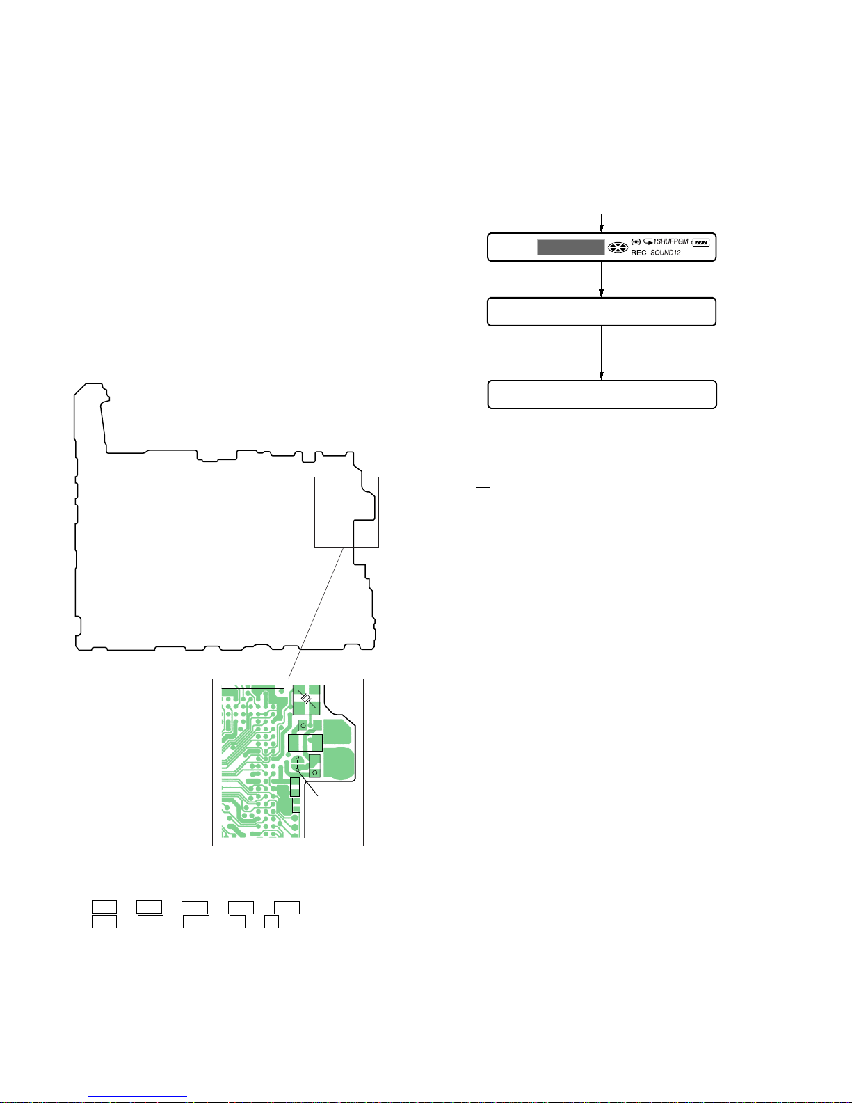
MZ-R900
888
003 V1.000
Microcomputer
version
display
Destination code
002 : Except US, Canadian models
003 : US, Canadian models
All off
All lit
BASS12
C830
+
L801
C809
+
C813
C801
1112241
51048
316
7229
9419
189596
22827
341521
381723
401628
262025
4224113
513031
453635
475044
534959
565455
615762
5860
68
63
81
137
65
70
135
67
77
133
74
79
1
667376
4
0
3
IC801
SL801
(TEST)
– MAIN Board (Conductor Side) –
2 In the normal mode, turn on the [HOLD] switch. While press-
ing the [VOL --] key press the following order:
> t > t . t . t > t
. t > t . t X t X
SECTION 4
TEST MODE
Operation in Setting the Test Mode
• When the test mode becomes active, first the display check mode
is selected.
• Other mode can be selected from the display check mode.
• When the test mode is set, the LCD repeats the following display.
Remote commander LCD display
• When the X key is pressed and hold down, the display at that
time is held so that display can be checked.
Caution: On the set having the microcomputer version 1.000,
some adjusted values were set in the manual mode at
the shipment, but these data will be cleared when the
NV is reset. Therefore, on the set having the microcomputer version 1.000, change the adjusted values
following the Change of Adjusted Values immediately
after the NV was reset (see page 17).
Releasing the Test Mode
For test mode set with the method 1:
Turn off the power and open the solder bridge on SL801 (TEST)
on the MAIN board.
Note: Remove the solders completely. Remaining could be shorted with
the chassis, etc.
For test mode set with the method 2:
Turn off the power.
Note: If electrical adjustment (see page 17) has not been finished com-
pletely, always start in the test mode. (The set cannot start in normal mode)
Outline
• This set provides the Overall adjustment mode that allows CD
and MO discs to be automatically adjusted when in the test mode.
In this overall adjustment mode, the disc is discriminate between
CD and MO, and each adjustment is automatically executed in
order. If a fault is found, the system displays its location. Also,
the manual mode allows each individual adjustment to be automatically adjusted.
• Operation in the test mode is performed with the set. A key
having no particular description in the text, indicates a set key.
• For the LCD display, the LCD on the remote commander is
shown, but the contents of LCD display on the set are same.
Setting Method of Test Mode
There are two different methods to set the test mode:
1 Short SL801 (TEST) on the MAIN board with a solder bridge
(connect pin 3 of IC801 to the ground). Then, turn on the
power.
13
MZ-R900
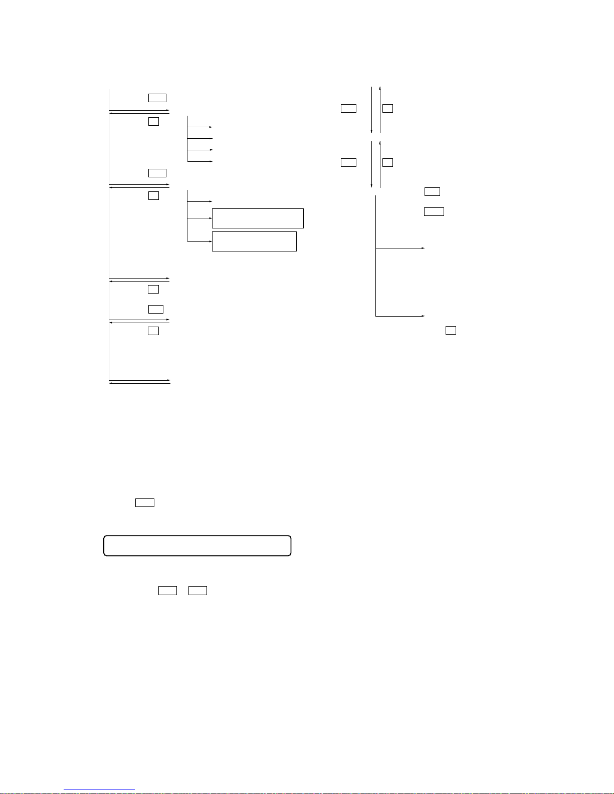
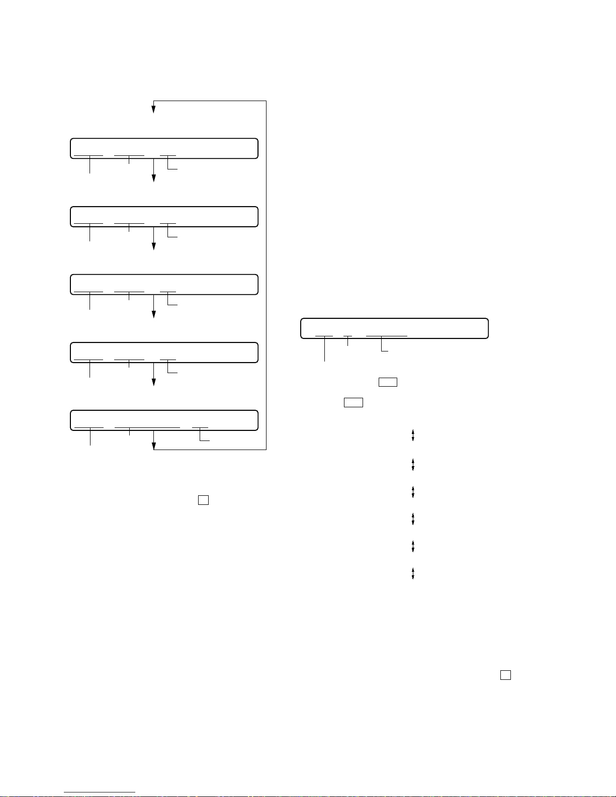
Configuration of Test Mode
Manual Mode
Mode to adjust or check the operation of the set by function.
Normally, the adjustment in this mode is not executed.
However, the Manual mode is used to clear the memory, power
supply adjustment, and laser power check before performing
automatic adjustments in the Overall Adjustment mode.
• Transition method in Manual Mode
1. Setting the test mode (see page 12).
2. Press the > or[VOL +] key activates the manual mode where
the LCD display as shown below.
3. During each test, the optical pick-up moves outward or inward while the > or . key is pressed for several seconds respectively.
4. Each test item is assigned with a 3-digit item number;
100th place is a major item, 10th place is a medium item, and
unit place is a minor item.
The values adjusted in the test mode are written to the
nonvolatile memory (for the items where adjustment was
made).
Remote commander LCD display
000 Manual
[Manual Mode]
[Servo Adjustment]
[Audio Adjustment]
[Power Supply Adjustment]
[OP Alignment Adjustment]
[Overall Adjustment Mode]
[Sound Skip Check Result Display Mode]
[Key Check Mode]
[Test Mode $Display Check Mode%]
Press the
x
key
Press the
x
key
Press the
x
key
Press the
.
or
[VOL --]
key
Press the
N
or
[REC]
key
Press the
>
or
[VOL +]
key
[Electrical Offset Adjustment]
Power Supply Adjustment
Auto Item Feed
CD Overall Adjustment/
MO Overall Adjustment
[Self-Diagnosis Result Display Mode]
Press the
x
key
Press the
[JOG LEVER $L% ]
(up) key,
or
[DISPLAY]
key on the remote commander
Press the
[T MARK]
key, or
[DISPLAY]
key
on the remote commander for several
seconds (about 3 seconds)
The key check quits, or open the upper panel
R
[VOL +]
key:100th place of item number
increase.
[VOL --]
key:100th place of item number
decrease.
[Major item switching]
[VOL +]
key:10th place of item number
increase.
[VOL --]
key:10th place of item number
decrease.
[VOL +]
key:Increases the
adjusted value
[VOL --]
key:Decreases the
adjusted value
[Medium item switching]
N
key
N
key
x
key
[Minor item switching]
[Adjusted value variation]
X
key: When adjusted value is
changed:
Adjusted value is written.
When adjusted value is
not changed:
That item is adjusted
automatically.
[Adjusted value write]
N
key: Unit place of item number
increase.
.
key:Unit place of item number
decrease.
x
key
14
MZ-R900
Self-Diagnosis Result Display Mode
This set uses the self-diagnostic function system in which if an
error occurred during the recording or playing, the mechanism
control block and the power supply control block in the
microcomputer detect it and record its cause as history in the
nonvolatile memory.
By checking this history in the test mode, you can analyze a fault
and determine its location.
Total recording time is recorded as a guideline of how long the
optical pickup has been used, and by comparing it with the total
recording time at the time when an error occurred in the selfdiagnosis result display mode, you can determine when the error
occurred.
Clear both self-diagnosis history data and total recording time, if
the optical pickup was replaced.
• Self-Diagnosis Result Display Mode Setting Method
1. Setting the test mode (see page 12).
2. In the display check mode, press the [JOG LEVER $L% ] (up)
key or [DISPLAY] key on the remote commander activates the
self-diagnosis result display mode where the LCD display as
shown below.
3. Then, each time the > key is pressed, LCD display descends
by one as shown below. Also, the LCD display ascends by one
when the
. key is pressed.
If the [JOG LEVER $L% Q] (up) key or the [DISPLAY] key on
remote commander is pressed with this display, the LCD switches
to the simple display mode.
4. Quit the self-diagnosis result display mode, and press the x key
to return to the test mode (display check mode).
5. The display changes a shown below each time the
[JOG LEVER $L% ] (up) ke y or [DISPLAY] ke y on the remote
commander is pressed.
However in the power mode (item number 700’s), only the
item is displayed.
6. Quit the manual mode, and press the
x key to return to the
test mode (display check mode).
Overall Adjustment Mode
Mode to adjust the servo automatically in all items.
Normally, automatic adjustment is executed in this mode at the
repair.
For further information, refer to “Section 5 Electrical Adjustments”
(see page 17).
• Address & Adjusted Value Display
Remote commander LCD display
• Jitter Value & Adjusted Value Display
Remote commander LCD display
• Block Error Value & Adjusted Value Display
Remote commander LCD display
• ADIP Error Value & Adjusted Value Display
Remote commander LCD display
• Item Title Display
Remote commander LCD display
item number
address
adjusted value
item number
jitter value
adjusted value
item number
block error value
adjusted value
item number
ADIP error value
adjusted value
item number
item title
adjusted value
011 C68S01
011 OFFJ01
011 063B01
011 059A01
011 LrefPw 01
R
R
0XX 1 0000
Remote commander LCD display
history code
Total recording time when error occurre
d
error display code
0XX 1 ****
0XX N ****
0XX N1****
0XX N2****
0XX R_****
1
1
XX
: Error code
****
: Total recording time
15
MZ-R900
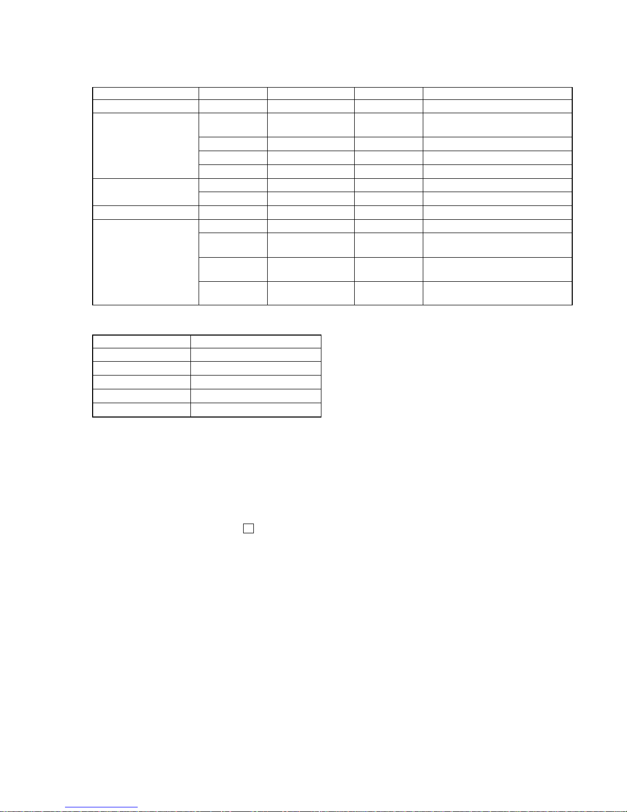
• Description of Indication History
History code number Description
1 The first error
N The last error
N1 One error before the last.
N2 Two errors before the last.
R_ Total recording time
Reset the error display code
After servicing, reset the error display code.
• Setting method of Reset the Error Display Code
1. Setting the test mode (see page 12).
2. Press the [JOG LEVER $L% ] (up) key or [DISPLAY] key on the
remote commander activates the self-diagnosis result display
mode.
3. T o reset the error display code, press the X key (2 times) when
the code is displayed (except “R_****”).
(All the data on the 1, N, N1, and N2 will be reset)
• Description of Error Indication Codes
Problem Indication code Meaning of code Simple display Description
No error 00 No error --- No error
01
Illegal access target
Adrs Attempt to access an abnormal address
address was specified
Servo system error 02 High temperature Temp High temperature
03 Focus error Fcus Disordered focus
04 Spindle error Spdl Abnormal rotation of disc
TOC error
11 TOC error TOC Faulty TOC contents
12 Data reading error Data Data could not be read at SYNC
Power supply system error 22 Low battery LBat Momentary interruption detected
31 Offset error Ofst Offset error
32
Focus error ABCD
ABCD Focus error ABCD offset error
offset error
Offset system error
33
Tracking error
TE Tracking error Offset error
Offset error
34
X1 tracking error
X1TE X1 tracking error Offset error
Offset error
R
 Loading...