

Sony Walkman MZ-R70 Service Manual
– 1 –
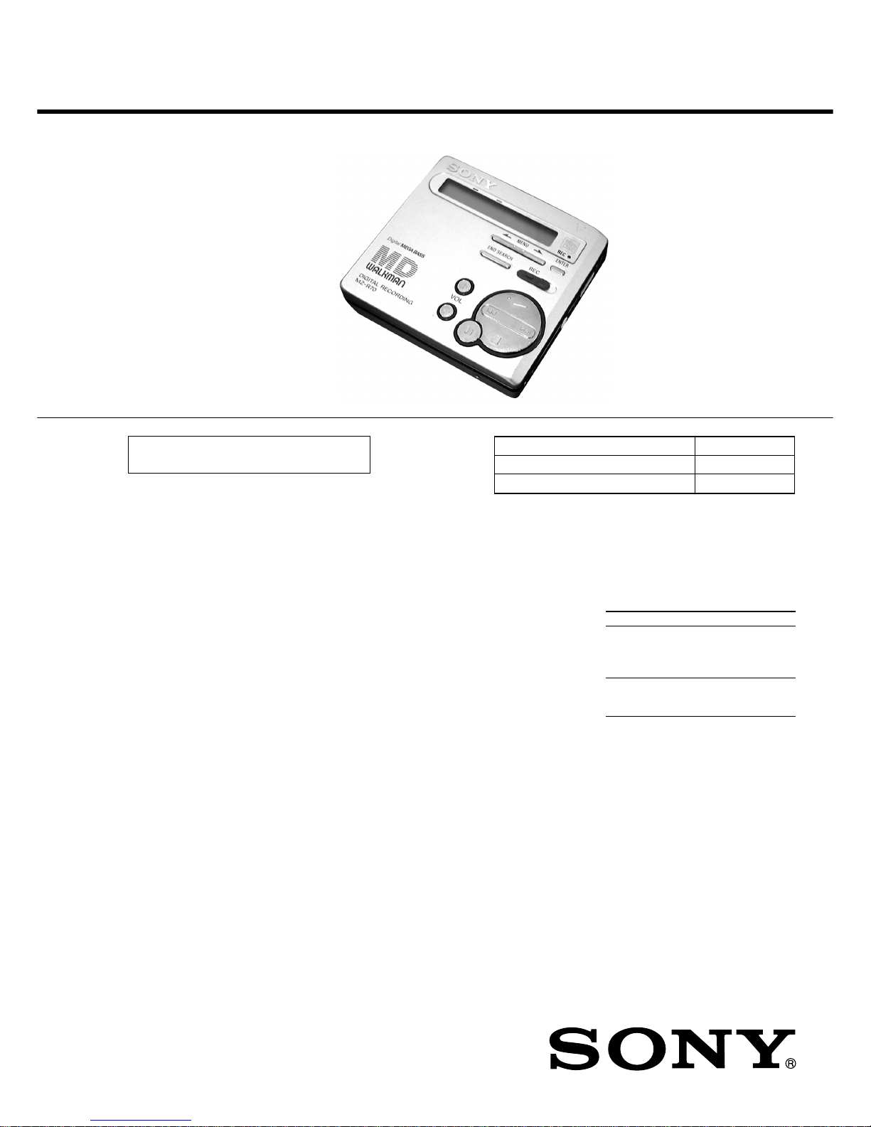
MZ-R70
SERVICE MANUAL
PORTABLE MINIDISC RECORDER
Model Name Using Similar Mechanism MZ-R90/R91
Mechanism Type MT-MZR70-165
Optical Pick-up Name LCX-2R
(Photo: Silver)
System
Audio playing system
MiniDisc digital audio system
Laser diode properties
Material: GaAlAs
Wavelength: λ = 790 nm
Emission duration: continuous
Laser output: less than 44.6 µW
(This output is the value measured at a
distance of 200 mm from the lens surface
on the optical pick-up block with 7 mm
aperture.)
Recording and playback time
Maximum 80 minutes (MDW-80, stereo
recording)
Maximum 160 minutes (MDW-80,
monaural recording)
Maximum 74 minutes (MDW-74, stereo
recording)
Maximum 148 minutes (MDW-74,
monaural recording)
Revolutions
400 rpm to 1,800 rpm (CLV)
Error correction
Advanced Cross Interleave Reed Solomon
Code (ACIRC)
Sampling frequency
44.1 kHz
Sampling rate converter
Input: 32 kHz/44.1 kHz/48 kHz
Coding
Adaptive TRansform Acoustic Coding
(ATRAC)
Modulation system
EFM (Eight to Fourteen Modulation)
Number of channels
2 stereo channels
1 monaural channel
SPECIFICATIONS
Frequency response
20 to 20,000 Hz ± 3 dB
Wow and Flutter
Below measurable limit
Inputs
Microphone: stereo mini-jack, 0.35–1.38
mV
Line in: stereo mini-jack, 69–194 mV
Optical (Digital) in: optical (digital) minijack
Outputs
i1: stereo mini-jack, maximum output
level 5 mW + 5 mW, load impedance 16
ohm
i2: stereo mini-jack, maximum output
level 5 mW + 5 mW, load impedance 16
ohm
General
Power requirements
Sony AC Power Adaptor (supplied)
connected at the DC IN 3 V jack:
120 V AC, 60 Hz (US model)
230-240 V AC, 50/60 Hz (UK and Hong
Kong model)
240 V AC, 50/60 Hz (Australia and New
Zealand model)
220-230 V AC, 50/60 Hz (European
model)
220 V AC, 50 Hz (China model)
220 V AC, 50 Hz (Argentina model)
100-240 V AC, 50/60 Hz (Other models)
Nickel cadmium rechargeable battery
NC-WMAA (supplied)
LR6 (size AA) alkaline battery (not
supplied)
Battery operation time
Battery life
1)
Batteries Recording2)Playback
NC-WMAA Approx. Approx.
nickel cadmium 3 hours 6.5 hours
rechargeable
battery
LR6 (size AA) Approx. Approx.
Sony alkaline 3 hours
3)
17 hours
dry battery
1)
The battery life may be shorter due to
operating conditions and the temperature
of the location.
2)
When you record, use a fully charged
rechargeable battery.
3)
Recording time may differ according to
the alkaline batteries.
– Continued on next page –
US Model
Canadian Model
AEP Model
UK Model
E Model
Australian Model
Chinese Model
Tourist Model
US and foreign patents licensed from Dolby
Laboratories Licensing Corporation.
Ver 1.3 2001. 01
With SUPPLEMENT-1
(9-927-631-81)
– 2 –
Flexible Circuit Board Repairing
• Keep the temperature of the soldering iron around 270°C
during repairing.
• Do not touch the soldering iron on the same conductor of the
circuit board (within 3 times).
• Be careful not to apply force on the conductor when soldering
or unsoldering.
Notes on chip component replacement
• Never reuse a disconnected chip component.
• Notice that the minus side of a tantalum capacitor may be
damaged by heat.
CAUTION
Use of controls or adjustments or performance of procedures
other than those specified herein may result in hazardous
radiation exposure.
IN NO EVENT SHALL SELLER BE
LIABLE FOR ANY DIRECT,
INCIDENTAL OR CONSEQUENTIAL
DAMAGES OF ANY NATURE, OR
LOSSES OR EXPENSES RESULTING
FROM ANY DEFECTIVE PRODUCT
OR THE USE OF ANY PRODUCT.
“MD WALKMAN” is a trademark of Sony
Corporation.
This MiniDisc player is classified as a CLASS 1 LASER
product.
The CLASS 1 LASER
PRODUCT label is located on
the bottom exterior.
Dimensions
Approx. 81 × 74 × 26.2 mm (w/h/d)
(3 1/4 × 3 × 1 1/16 in.) without projections.
Mass
Approx. 115 g (4 oz) the recorder only
Approx. 155 g (5.4 oz) incl. a recordable
MD, and NC-WMAA nickel cadmium
rechargeable battery
Supplied accessories
AC power adaptor (1)
Headphones with a remote control (1)
Optical cable (1)
NC-WMAA nickel cadmium rechargeable
battery (1)
Rechargeable battery carrying case (1)
Carrying pouch (1)
Design and specifications are subject to change
without notice.
SAFETY-RELATED COMPONENT WARNING!!
COMPONENTS IDENTIFIED BY MARK 0 OR DOTTED LINE
WITH MARK 0 ON THE SCHEMATIC DIAGRAMS AND IN
THE PARTS LIST ARE CRITICAL TO SAFE OPERATION.
REPLACE THESE COMPONENTS WITH SONY PARTS WHOSE
PART NUMBERS APPEAR AS SHOWN IN THIS MANUAL
OR IN SUPPLEMENTS PUBLISHED BY SONY.
ATTENTION AU COMPOSANT AYANT RAPPORT
À LA SÉCURITÉ!!
LES COMPOSANTS IDENTIFIÉS P AR UNE MARQUE 0 SUR LES
DIAGRAMMES SCHÉMATIQUES ET LA LISTE DES PIÈCES
SONT CRITIQUES POUR LA SÉCURITÉ DE FONCTIONNEMENT .
NE REMPLACER CES COMPOSANTS QUE PAR DES PIÈCES
SONY DONT LES NUMÉROS SONT DONNÉS D ANS CE MANUEL
OU DANS LES SUPPLÉMENTS PUBLIÉS PAR SONY.

– 3 –
1. SERVICING NOTE ......................................................... 4
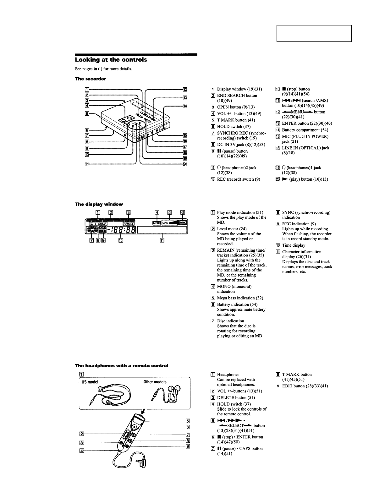
2. GENERAL......................................................................... 5
Looking at the Controls ........................................................5
Recording an MD Right Away! ............................................ 6
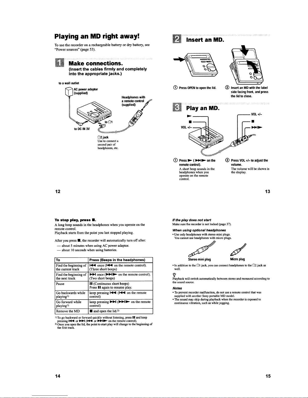
Playing an MD Right Away! ................................................. 7
3. DISASSEMBLY ............................................................... 8
3-1. Block Assy, Bottom ..............................................................8
3-2. Panel Block Assy, Upper....................................................... 8
3-3. LCD Module ......................................................................... 9
3-4. Main Board ........................................................................... 9
3-5. MD Mechanism Deck ......................................................... 10
3-6. Service Assy, OP ................................................................. 10
3-7. Holder Assy.........................................................................11
3-8. Motor Flexible Board .......................................................... 11
3-9. Motor, DC (M602) .............................................................. 12
3-10. “Motor, DC (M601)”, “Motor, DC (M603)” .................... 12
4. TEST MODE...................................................................13
4-1. Outline................................................................................. 13
4-2. Test Mode............................................................................13
4-3. Manual Mode ...................................................................... 14
4-4. Overall Adjustment Mode................................................... 15
4-5. Sound Skip Check Result Display Mode ............................ 16
4-6. Self-diagnosis Display Mode .............................................. 17
4-7. Key Check Mode.................................................................19
TABLE OF CONTENTS
5. ELECTRICAL ADJUSTMENTS.............................. 20
5-1. Outline................................................................................. 20
5-2. Precautions for Adjustment................................................. 20
5-3. Adjustment Sequence .......................................................... 20
5-4. NV Reset ............................................................................. 20
5-5. Power Supply Manual Adjustment...................................... 20
5-6. Temperature Correction.......................................................22
5-7. Overall Adjustment Mode................................................... 22
5-8. Laser Power Check ............................................................. 23
6. DIAGRAMS..................................................................... 25
6-1. Block Diagram – MD Section –.......................................... 25
6-2. Block Diagram – Audio Section – ...................................... 27
6-3. Block Diagram – Power Supply Section –.......................... 29
6-4. Printed W iring Board – Main Board –................................ 31
6-5. Schematic Diagram – Main Board (1/3) – .......................... 35
6-6. Schematic Diagram – Main Board (2/3) – .......................... 37
6-7. Schematic Diagram – Main Board (3/3) – .......................... 39
6-8. IC Block Diagrams..............................................................41
6-9. IC Pin Descriptions ............................................................. 44
7. EXPLODED VIEWS..................................................... 51
7-1. Cabinet Section ................................................................... 51
7-2. Mechanism Deck Section ................................................... 52
8. ELECTRICAL PARTS LIST...................................... 53
– 4 –
SECTION 1
SERVICING NOTE
NOTES ON HANDLING THE OPTICAL PICK-UP
BLOCK OR BASE UNIT
The laser diode in the optical pick-up block may suffer electrostatic break-down because of the potential difference generated
by the charged electrostatic load, etc. on clothing and the human
body.
During repair, pay attention to electrostatic break-down and also
use the procedure in the printed matter which is included in the
repair parts.
The flexible board is easily damaged and should be handled with
care.
NOTES ON LASER DIODE EMISSION CHECK
Never look into the laser diode emission from right avove when
checking it for adustment. It is feared that you will lose your sight.
NOTES ON HANDLING THE OPTICAL PICK-UP BLOCK
(LCX-2R)
The laser diode in the optical pick-up block may suffer electrostatic
break-down easily. When handling it, perform soldering bridge to
the laser-tap on the flexible board. Also perform measures against
electrostatic break-down sufficiently before the operation. The
flexible board is easily damaged and should be handled with care.
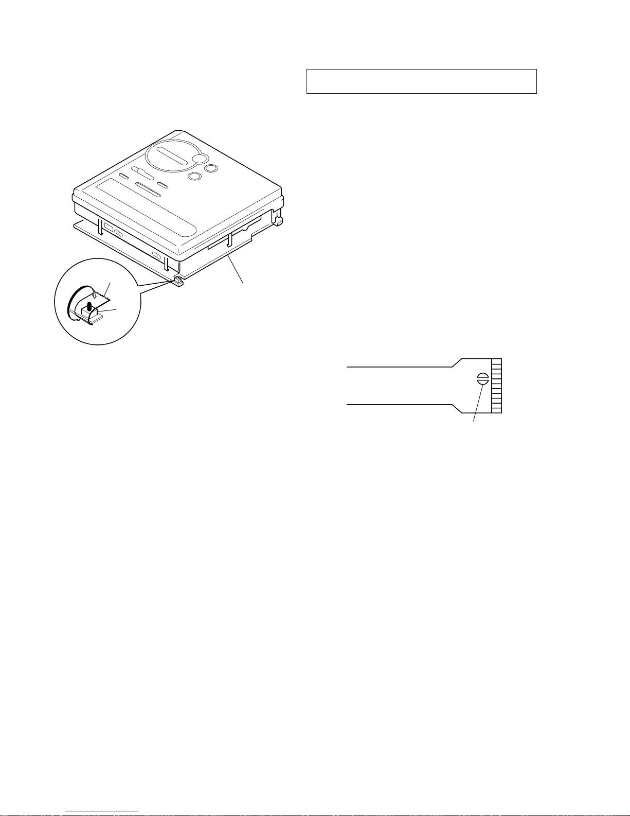
OPTICAL PICK-UP FLEXIBLE BOARD
• When repairing this device with the power on, if you remove
the MAIN board or open the upper panel assy , this device stops
working.
In this case, you can work without the device stopping by fastening the hook of the open/close detect switch (S801) with tape.
• This set is designed to perform automatic adjustment for each
adjustment and write its value to EEPROM. Therefore, when
EEPROM (IC802) has been replaced in service, be sure to perform automatic adjustment and write resultant values to the new
EEPROM.
(Refer to page 20.)
• Replacement of CXD2660R (IC502) and CXR701081 (IC801)
used in this set requires a special tool. Therefore, they cannot be
replaced.
laser-tap
Tape
S801
MAIN board
– 5 –
SECTION 2
GENERAL
This section is extracted from
instruction manual.
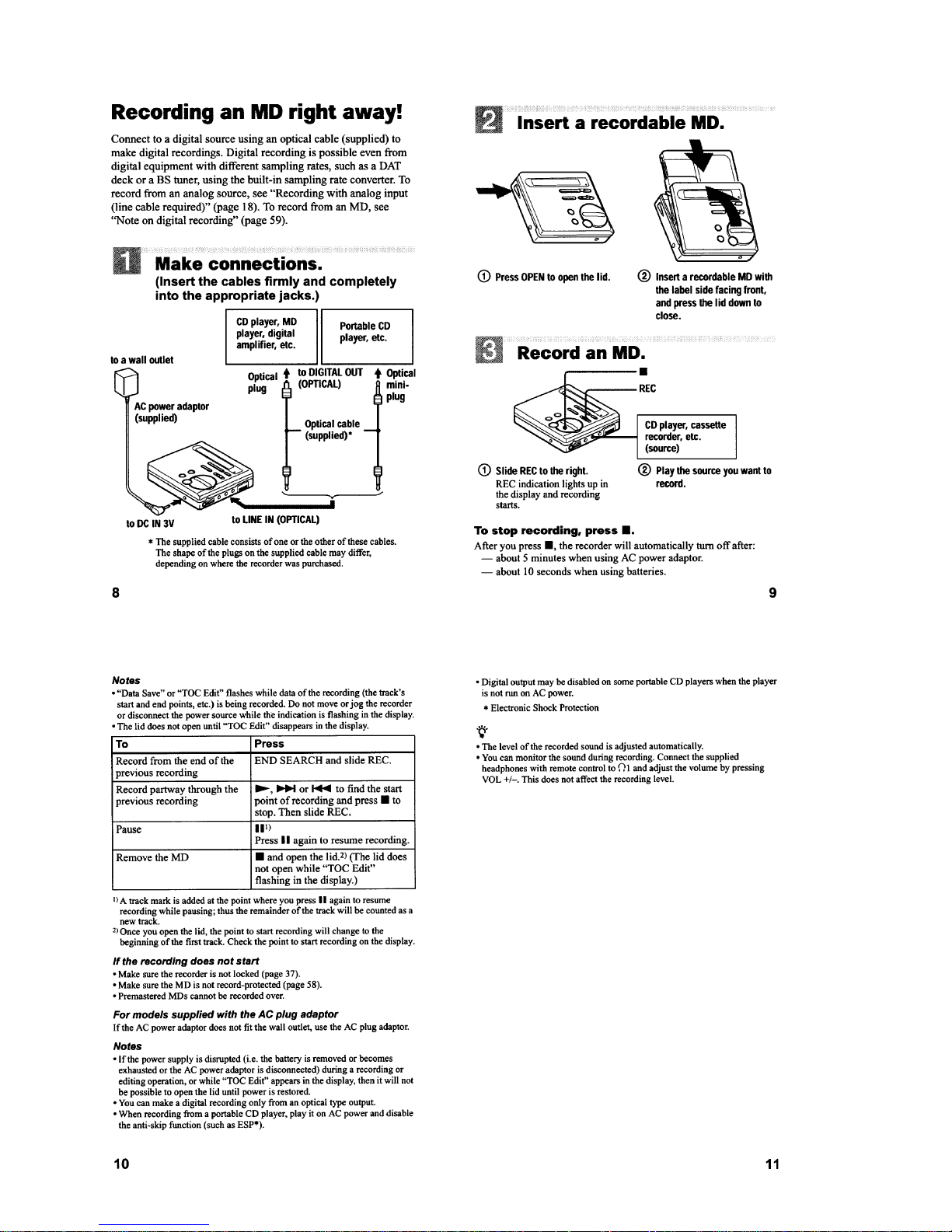
– 6 –
– 7 –
– 8 –
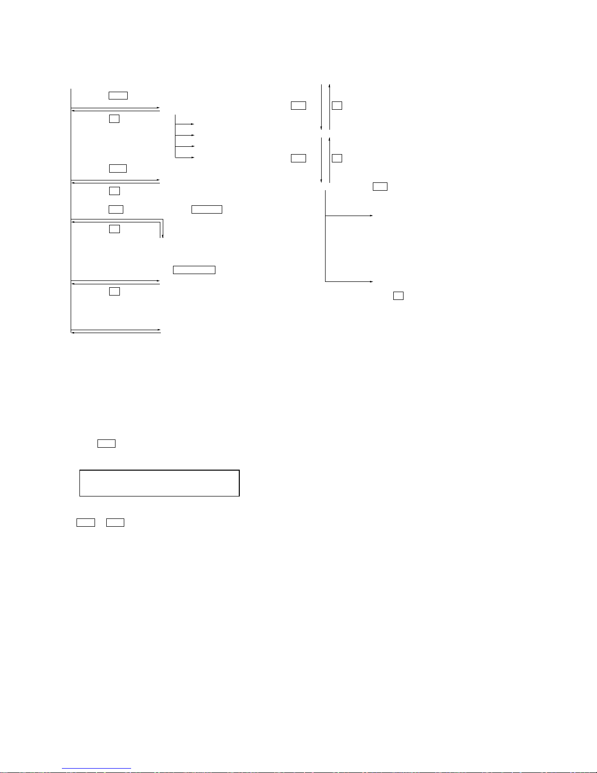
Note : This set can be disassemble according to the following sequence.
SECTION 3
DISASSEMBLY
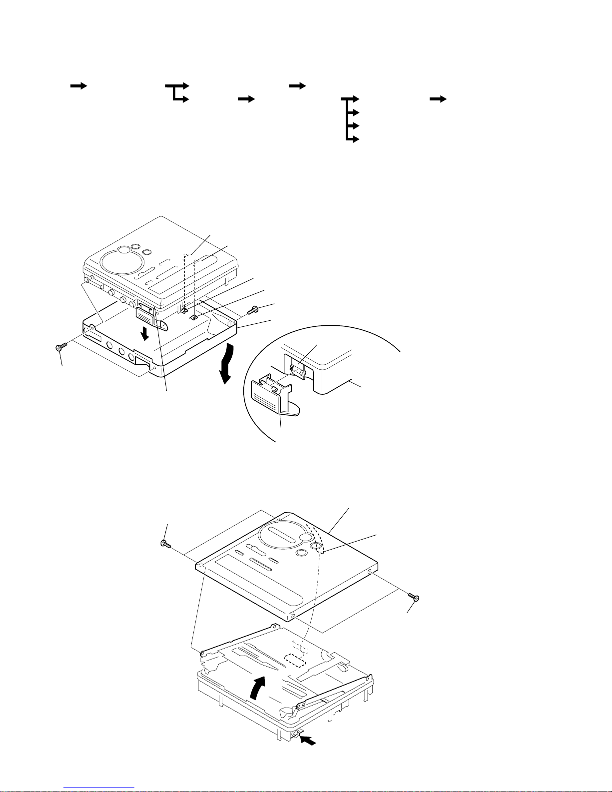
3-1. BLOCK ASSY, BOTTOM
3-2. PANEL BLOCK ASSY, UPPER
Note : Follow the disassembly procedure in the numerical order given.
Set Block Assy, Bottom Panel Block Assy, Upper LCD Module
Main Board MD Mechanism Deck
Service Assy, OP
Motor Flexible Board
Holder Assy
Motor, DC (M602)
“Motor, DC (M601)”, “Motor, DC (M603)”
1 CN801
2
3
4 screws (1.4)
5 screws (1.4)
6 panel block assy, upper
Note : When installing, fit the knobs (HOLD, SYNCHRO REC) and switches (S804, S807)
1 lid, battery case
lid, battery case
6 block assy, bottom
block assy, bottom
3 screws (1.4)
knob (HOLD)
knob (SYNCHRO REC)
hinge
S807
S804
4 screws (1.4)
2
5
Note:When installing the bottom block assy,
install the assy with the battery case lid open.
After it is installed, close the battery case lid.
– 9 –
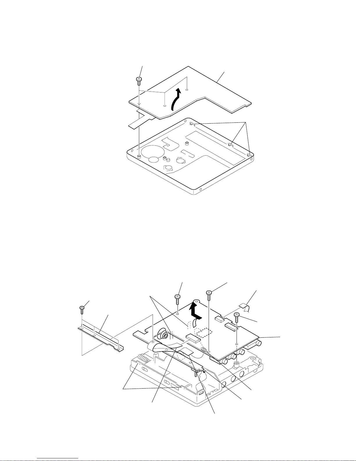
3-3. LCD MODULE
3-4. MAIN BOARD
1 screws (1.7)
3 LCD module
claws
2
4 screw (1.4)
qs
5 screw (1.4)
8 screw (1.7)
6 screws (1.7)
7 stay
1 CN601
qd CN501
3 Remove the solder.
qa boss
qf MAIN boar
d
2 CN602
9 claws
0 claws
– 10 –
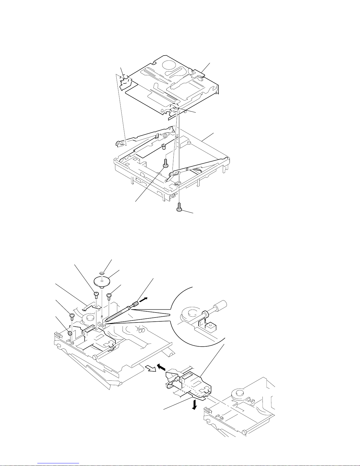
3-5. MD MECHANISM DECK
(MT-MZR70-165)
3-6. SERVICE ASSY, OP
3 boss
4 boss
chassis assy
5 MD mechanism deck
(MT-MZR70-165)
1 screw (1.4)
2 screw (1.4)
9 bearing
5 screw
4 rack spring
3 precision pan screw
(M1.4)
1 washer (0.8 - 2.5)
2 gear (SA)
6 screw
8 Pull off the lead screw.
7
B
A
0 Opening the over write head
toward the direction A, remove th
e
OP Service assy toward
the direction B.
Note: Do not open the entire assy
forcibly, when opening
the over write head.
over write head section
– 11 –
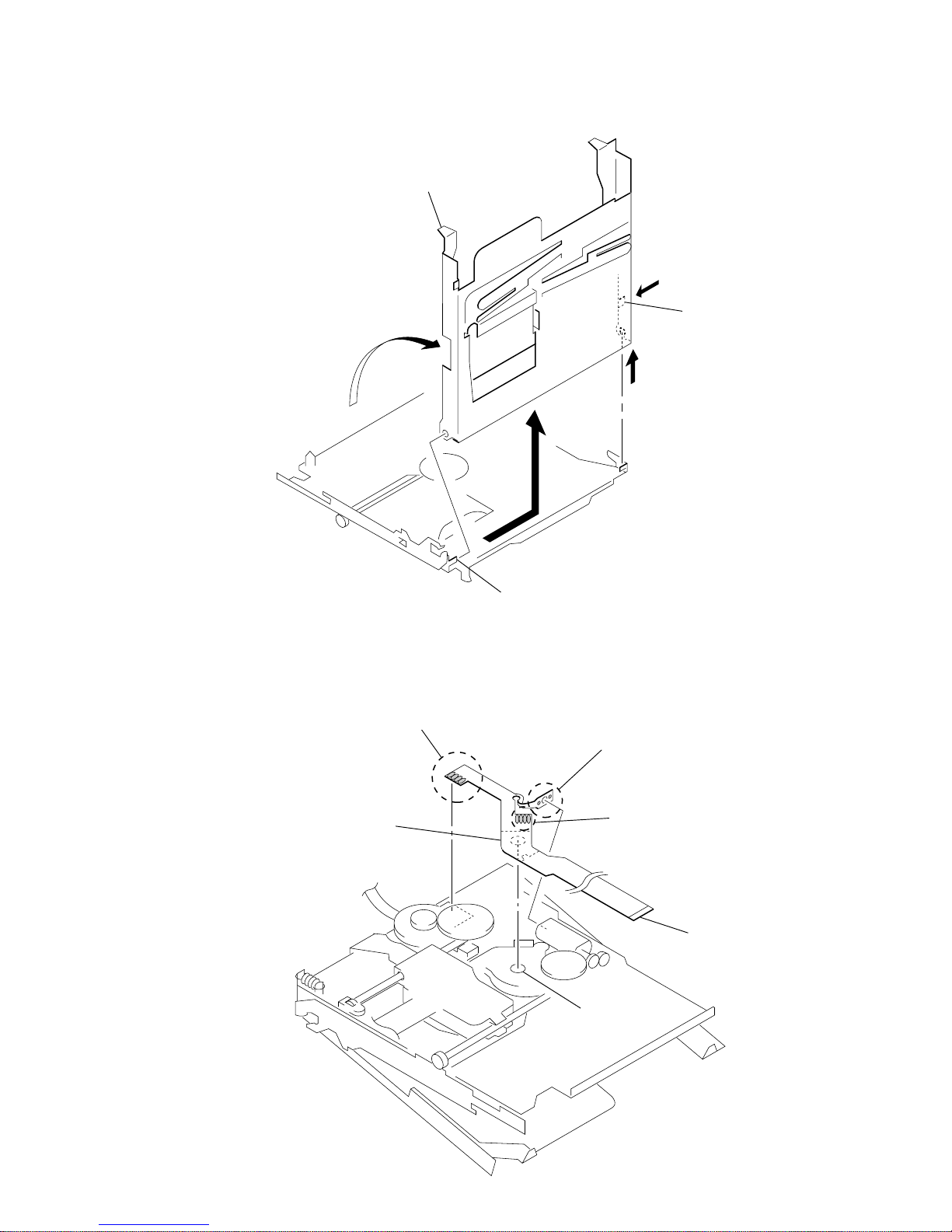
3-7. HOLDER ASSY
2 Remove two solders of
DC motor (over write head up/down) (M603).
1 Remove four solders of
DC motor (sled) (M602).
3 Remove four solders of
DC motor (spindle) (M601).
DC motor (sled)
circular hole
5 motor flexible board
4 adhesive sheet
Note: Align a circular hole in the stripping paper
with a circular hole in the DC motor (sled),
when mounting the motor
flexible board.
3-8. MOTOR FLEXIBLE BOARD
5 Remove the holder assy to
direction of the arrow C.
1 Open the holder assy.
A
B
3
C
2 Push the convex portion
toward the direction B and
open the holder assy toward
the direction A to erect uprightly.
4 boss
– 12 –
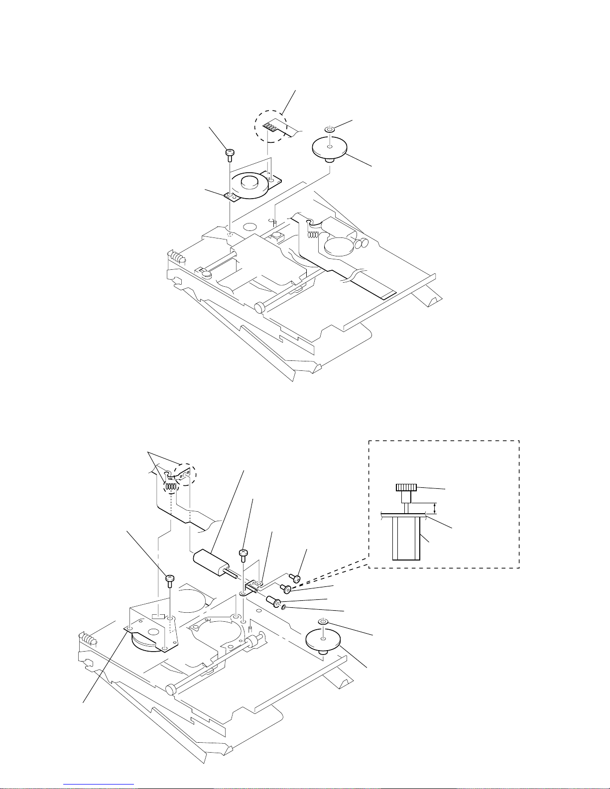
4 two precision pan screws
(M1.4)
5 DC motor (sled) (M602)
1 Remove four solders of
motor flexible board.
2 washer (0.8 - 2.5)
3 gear (SA)
1 Remove six solders of
motor flexible board.
4 three precision pan screws
(M1.4)
qs DC motor (over write head up/down)
(M603)
6 two precision pan screws
(M1.4)
qa gear chassis assy
0 screw
(M1.2 × 1.5)
9 gear (HA)
8 gear (HB)
7 washer (0.8 - 2.5)
2 washer (0.8 - 2.5)
3 gear (HC)
5 DC motor
(spindle)
(M601)
DC motor
(over write head up/down)
(M603)
gear chassis assy
gear (HA)
2.65 mm
Note: Press-fit the gear (HA) up to the
position of the DC motor (over write
head up/down) (M603) as shown
below.
3-9. MOTOR, DC (M602)
3-10. “MOTOR, DC (M601)”, “MOTOR, DC (M603)”
– 13 –
IC502
FB501
C530
25
26
28
32
36
1
47
118
116
119
120
117
114113 112
115
110109 111
104108 106
104105 103
101102 100
144 146
37 46 47 50 53 56 59 64 68
42 45 48 51 55 57 60 63 66 67
145
88
88 87 86 83 81 78 74 72 69 64 63 60 58
90 89 85 84 80 77 75 71 68 65 62 59 57
93 92 91
96 95 94
99 98 97
82 79 76 73 70 67 66 61 55 56
52 53 54
49 50 51
46 47 48
43 45 44
40 41 42
37 36 39
34 35 36
32 33
26 28 31
25 29 30
19 22 27
21 23
20 24
10 13 16
11 14 17
12 15 18
74
268
1359
85
82
78
76
73
89
86
83
80
90
87
84
81
77
74
72
79
75
43 44 49 52 54 58 61 62 65 697071
38 40
39 41
AP508
AP504
AP505
R530
R529
C529
S804
HOLD
AP1001
L502
FB503FB502
FB504
BP801
AP519
AP830
AP521
OFF ON
R506
R503
R508
R509
R510
C537
R935
AP5209
AP806
C801
AP911
AP807
AP907
AP834
AP517
X801
AP511
AP516
2
9
AP506
0
3
2
AP804
AP803
AP507
05
IC802
IC801
8
1
54
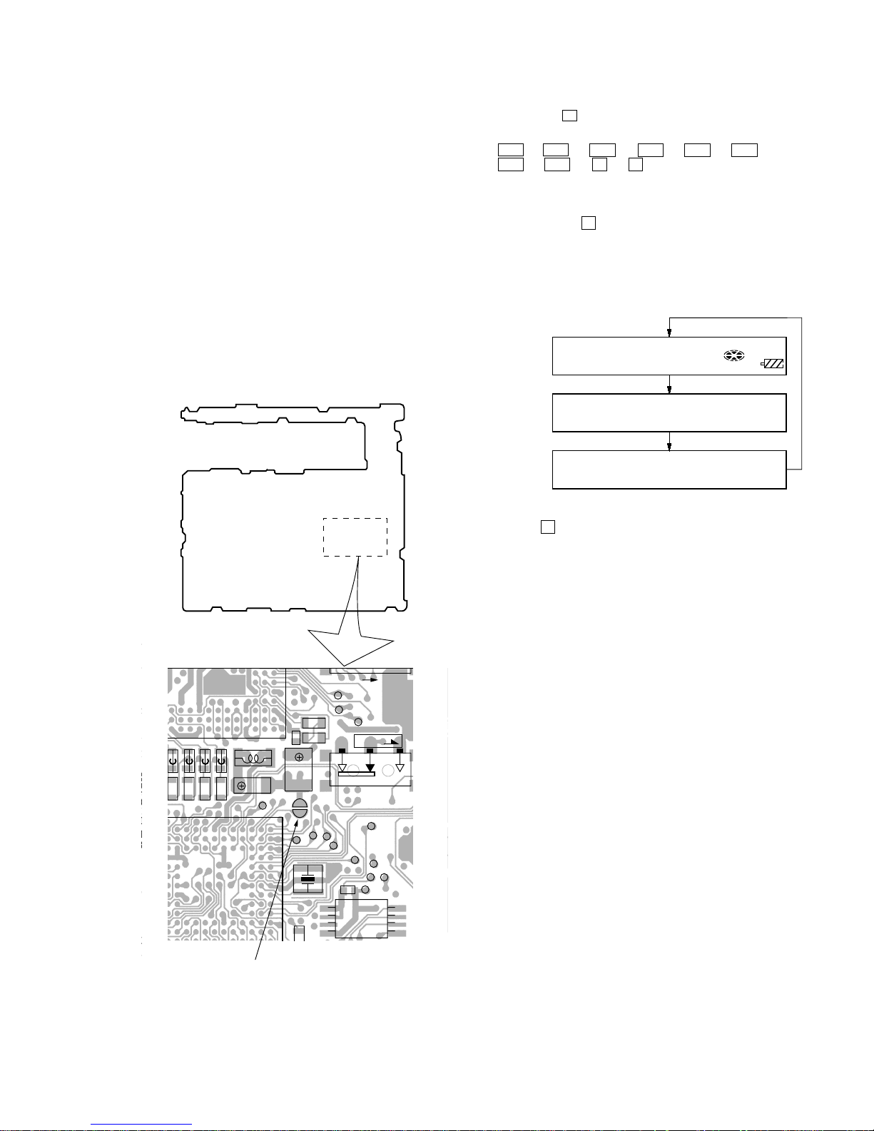
– MAIN BOARD (SIDE B) –
BP801
SECTION 4
TEST MODE
4-1. OUTLINE
• This set provides the Overall adjustment mode (Assy mode) that
allows CD and MO disc to be automatically adjusted when in
the test mode. In this overall adjustment mode, the protect switch
is detected to judge the disc, CD or MO, and each adjustment is
automatically executed in order. If a fault is found, the system
displays its location. Also, the manual mode allows each individual adjustment to be automatically adjusted.
• The keys in the description refer to the keys on both set and
remote commander unless otherwise specified. Though LCD
display shows the LCD of the remote commander, same contents are also displayed on the LCD of the set.
4-2. TEST MODE
4-2-1. Setting Method of Test Mode
There are two different methods to set the test mode:
1 Short BP801 (TEST) on the MAIN board with a solder bridge
(connect pin y; of IC801 to the ground). Then, turn on the
power.
2 In the normal mode, turn on the HOLD switch on the set. While
pressing the
x key on the set, press the following remote
control keys in the following order:
> t > t . t . t > t . t
> t . t X t X
4-2-2. Operation in Setting the Test Mode
• When the test mode becomes active, first the display check mode
is selected. (Press
x key once, when the display check mode
is not active.)
• Other mode can be selected from the display check mode.
• When the test mode is set, the LCD repeats the following dis-
play.
LCD display
• When the
X key is pressed and hold down, the display at that
time is held so that display can be checked.
4-2-3. Releasing the Test Mode
For test mode set with the method 1:
Turn off the power and open the solder bridge on BP801 (TEST)
on the MAIN board.
Note:Remove the solders completely. Remaining could be shorted with
the chassis, etc.
For test mode set with the method 2:
Turn off the power.
Note: If electrical adjustment (see page 20) has not been finished com-
pletely, always start in the test mode. (The set cannot start in normal mode.)
Microprocessor
version
display
All off
All lit
xxxxxxxxx
V0.000
888
001
F1SHUF
REC
– 14 –
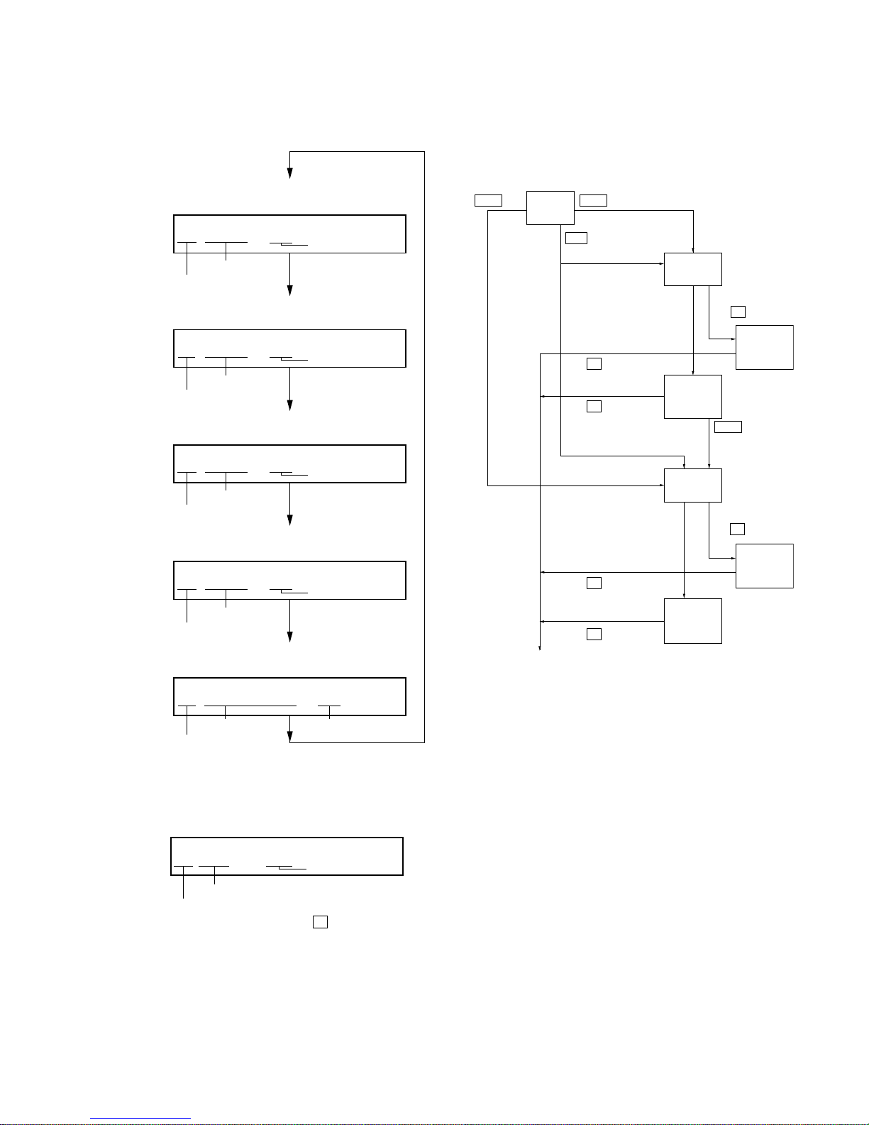
4-2-4. Configuration of Test Mode
Note: *1) on the set
*2) on the remote commander
*3) on the set or remote commander
4-3. MANUAL MODE
Mode to adjust or check the operation of the set by function.
Normally, the adjustment in this mode is not executed.
• Transition method in Manual Mode
1. Setting the test mode. (See page 13)
2. Press the
> or [VOL +] key activates the manual mode
where the LCD display as shown below.
3. The optical pick-up moves outward or inward while
the
> or . key is pressed for several seconds respec-
tively.
4. Each test item is assigned with a 3-digit mode number;
100th place is a major item, 10th place is a medium item, and
unit place is a minor item.
[Manual Mode]
[Servo Mode]
[Audio Mode]
[Power Mode]
[OP Alignment Mode]
[Overall Adjustment Mode]
[Self-Diagnosis Display Mode]
Press the > *
1)
or
[VOL +] *
3)
key
[Key Check Mode]
[Test Mode $Display Check Mode%]
Press the x *
3)
key
Press the x *
3)
key
Press the x *
3)
key
Press the x *
3)
key
Press the . *
3)
or [VOL --] *3) key
Press the N *
1)
or [REC] *1) or N > *2) key
press the [DISPLAY] *
2)
or MENU . *1) key
Press the
[T MARK] *
3)
or [DISPLAY] *2) key
on the remote commander for several seconds.
Quit the key check or open the upper panel
[Sound Skip Check Result Display Mode]
LCD display
Manual
000
[VOL +] key:100th place of mode number
increase.
[VOL --] key:100th place of mode number
decrease.
[Major item switching]
[VOL +]
key:10th place of mode number
increase.
[VOL --] key:10th place of mode number
decrease.
[VOL +] key:Increases the
adjusted value
[VOL --] key:Decreases the
adjusted value
[Medium item switching]
N key x key
[Minor item switching]
[Adjusted value variation]
X key: When adjusted value is
changed:
Adjusted value is written.
When adjusted value is
not changed:
That item is adjusted
automatically.
[Adjusted value write]
N key
N key: Unit place of mode number
increase.
x key
– 15 –
5. The display changes a shown below each time the jog key on
the set is turned up or
[DISPLAY] key on the remote com-
mander is pressed.
However in the power mode (mode number 700’s), only the
power adjustment value is displayed.
6. Quit the manual mode, and press
x key to return to the test
mode (display check mode).
AD 85
731
• Power Supply Adjusted Value
LCD display
mode number
fixed display
adjusted value
4-4. OVERALL ADJUSTMENT MODE
Mode to adjust the servo automatically in all items.
Normally, automatic adjustment is executed in this mode at the
repair.
Adjust the CD first, when performing adjustment.
• Configuration of overall adjustment
For further information, refer to the Section 5 Electrical Adjustment. (See page 20)
• Address & Adjusted Value Display
LCD display
• Jitter Value & Adjusted Value Display
LCD display
• Block Error Value & Adjusted Value Display
LCD display
• ADIP Error Value & Adjusted Value Display
LCD display
• Item Title Display
LCD display
C68S01
011
063B01
011
059A01
011
LrefPw 01
011
0FFJ01
011
mode number
address
adjusted value
mode number
jitter value
adjusted value
mode number
block error value
adjusted value
mode number
ADIP error value
adjusted value
adjusted value
mode number
item title
> key . key
> key
Title
display
CD overall
adjusting
CD overall
adjustment
OK
MO overall
adjusting
MO overall
adjustment
OK
CD overall
adjustment
NG
MO overall
adjustment
NG
N key
protect switch ON
All item
OK
protect switch OFF
NG item exists
or
x key
NG item exists
or
x key
x key
x key
x key
x key
[Test mode $display check mode%]
– 16 –
4. When [REC] key on the set is pressed, the total of error count
is displayed on the LCD, and each time the
> key is pressed,
the error count descents one by one as shown below. Also,
when
. key is pressed, the error count ascends by one.
If
N key is pressed, the error count during play is displayed.
**
: Sound skip check items counter (hexadecimal)
######
: 6-digit address (hexadecimal) where a sound skipped
last
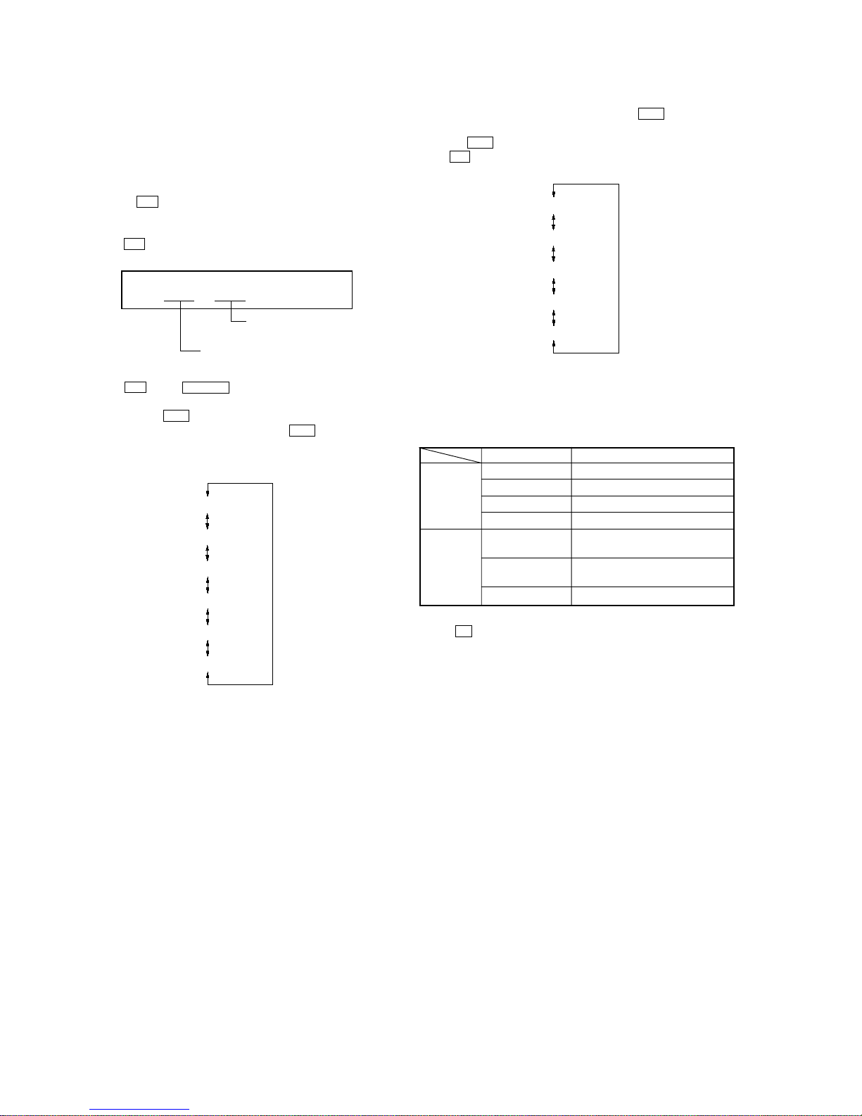
Error code
Cause of error Description of error
EIB Sound error correction error
Playback
Stat Decorder status error
Adrs Cannot access the address
BEmp Buffer becomes empty
BOvr Buffer becomes full and sounds are
dumped
Recording Bful Buffer capacity lowers and data are
forcibly written
Rtry Retry count over
5. Quit the sound skip check result display mode, and press
the
x key to return to the test mode (display check mode).
4-5. SOUND SKIP CHECK RESUL T DISPLAY MODE
This set can display and check the error count occurring during
record and play.
• Setting method of Sound Skip Check Result Display
Mode
1. Setting the test mode. (See page 13)
2. Press the
N or [REC] key on the set activates the sound skip
check result display mode where the LCD displays as shown
below.
When
N or [REC] key on the set is pressed:
3. When N key or N> key on the remote commander is
pressed, the total of error count is displayed on the LCD, and
each time the
> key is pressed, the error count descents
one by one as shown below. Also, when
. key is pressed,
the error count ascends by one. If
[REC] key on the set is
pressed, the error count during record is displayed.
**
: Sound skip check items counter (hexadecimal)
######
: 6-digit address (hexadecimal) where a sound skipped
last
LCD display
P**R**
000
Total of play system error count
Total of record system
error count
Stat**
000
Adrs**
000
BEmp**
000
######
000
P**R**
000
EIB **
000
Bful**
000
Rtry**
000
######
000
P**R**
000
BOvr**
000
 Loading...