

Sony Walkman MZ-E300 Service Manual
Ver 1.2 2001.12
MZ-E300
SERVICE MANUAL
PORTABLE MINIDISC PLAYER
SPECIFICATIONS
US Model
Canadian Model
AEP Model
E Model
Chinese Model
Model Name Using Similar Mechanism NEW
MD Mechanism Type MT-MZE300-176
Optical Pick-up Mechanism Type LCX-4E
US and foreign patents licensed from Dolby
Laboratories Licensing Corporation
System
Audio playing system
MiniDisc digital audio system
Laser diode properties
Material: GaAlAs
Wavelength: λ = 790 nm
Emission duration: continuous
Laser output: less than 44.6 µW*
* This output is the value measured at a distance of 200 mm from
the objective lens surface on the optical pick-up block with 7 mm
aperture.
Revolutions
Approx. 700 rpm to 1,500 rpm
Error correction
ACIRC (Advanced Cross Interleave Reed Solomon Code)
Sampling frequency
44.1 kHz
Coding
ATRAC (Adaptive TRansform Acoustic Coding)
Modulation system
EFM (Eight to Fourteen Modulation)
Number of channels
2 stereo channels
1 monaural channel
Frequency response
20 to 20,000 Hz ± 3 dB
Wow and Flutter
Below measurable limits
Power requirements
One LR6 (size AA) battery (not supplied)
Battery operation time
Battery life (EIAJ1))
Battery Playback
LR6 (SG) Sony Alkaline dry battery
2)
Approx. 33 hours
1)
Measured in accordance with the EIAJ (Electronic Industries
Association of Japan) standard (using a Sony MDW-series Mini-disc).
2)
When using a Sony LR6 (SG) “STAMINA” alkaline dry battery
(produced in Japan).
Note
The effective battery life may be shorter than that indicated above,
depending on operating conditions, the surrounding temperature, and
the battery type.
Dimensions
Approx. 83.0 x 26.7 x 76.5 mm (w/h/d) (3 3/8 x 1 1/16 x 3 1/8 in.)
(not including projecting parts and controls)
Mass
Approx. 83.0 g (3.0 oz) (the player only)
Supplied accessories
Headphones/earphones (1)
Design and specifications are subject to change without notice.
9-873-064-13
2001L0200-1
© 2001.12
Sony Corporation
Personal Audio Company
Published by Sony Engineering Corporation
2
MZ-E300
Specifications ........................................................................... 1
1. SERVICING NOTE ...................................................... 2
2. GENERAL
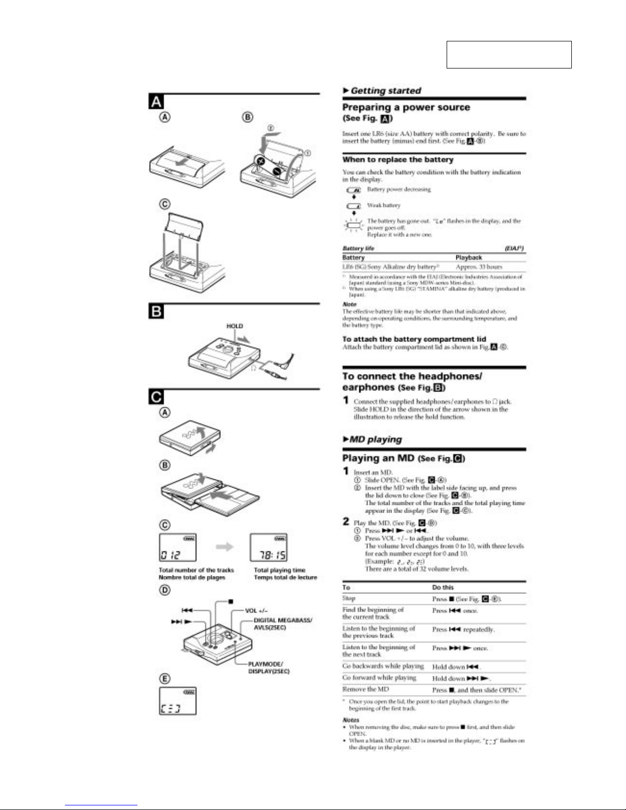
Preparing a Power Source .................................................. 3
To Connect the Headphones/Earphones ............................ 3
Playing an MD ................................................................... 3
3. DISASSEMBLY
3-1. “Lid ASSY, Upper”, Holder ASSY ............................ 4
3-2. Mechanism Deck ........................................................ 4
3-3. Main Board ................................................................. 5
3-4. Optical Pick-up ASSY ................................................ 5
4. TEST MODE.................................................................. 6
5. DIAGRAMS
5-1. Explanation of IC Terminals ..................................... 13
5-2. Block Diagram .......................................................... 18
5-3. Printed Wiring Boards – Main Section (1/2) – ......... 19
5-4. Printed Wiring Boards – Main Section (2/2) – ......... 20
5-5. Schematic Diagram – Main Section (1/3) – ............. 21
5-6. Schematic Diagram – Main Section (2/3) – ............. 22
5-7. Schematic Diagram – Main Section (3/3) – ............. 23
6. EXPLODED VIEWS
6-1. Main Section ............................................................. 29
6-2. Mechanism Deck Section ......................................... 30
7. ELECTRICAL PARTS LIST................................... 31
SAFETY-RELATED COMPONENT WARNING!!
COMPONENTS IDENTIFIED BY MARK 0 OR DOTTED LINE
WITH MARK 0 ON THE SCHEMATIC DIAGRAMS AND IN THE
PARTS LIST ARE CRITICAL TO SAFE OPERATION.
REPLACE THESE COMPONENTS WITH SONY PARTS WHOSE
PART NUMBERS APPEAR AS SHOWN IN THIS MANUAL OR IN
SUPPLEMENTS PUBLISHED BY SONY.
Flexible Circuit Board Repairing
• Keep the temperature of the soldering iron around 270°C during
repairing.
• Do not touch the soldering iron on the same conductor of the
circuit board (within 3 times).
• Be careful not to apply force on the conductor when soldering or
unsoldering.
Notes on chip component replacement
• Never reuse a disconnected chip component.
• Notice that the minus side of a tantalum capacitor may be damaged by heat.
TABLE OF CONTENTS
SECTION 1
SERVICING NOTE
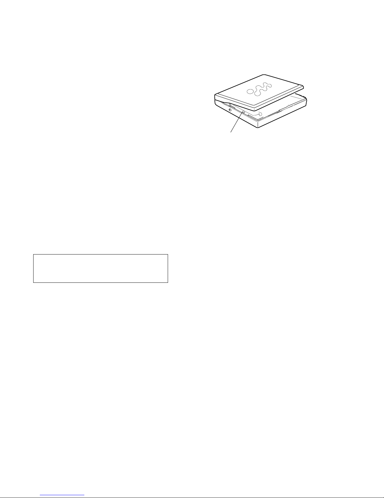
When repairing this device with the power on, if you remove the
main board, this device stops working.
In this case, you work without the device stopping by fastening
the hook of the Open/Close detection switch (S808).
CAUTION
Use of controls or adjustments or performance of procedures
other than those specified herein may result in hazardous
radiation exposure.
Open/Close detection switch (S808)
Note on IC replacement
If using flux on replacing IC801 etc., clean it with alcohol or
equivalent, and after that, check carefully there are no dust or
rags in between pins.
ATTENTION AU COMPOSANT AYANT RAPPORT
À LA SÉCURITÉ!
LES COMPOSANTS IDENTIFIÉS PAR UNE MARQUE 0 SUR LES
DIAGRAMMES SCHÉMATIQUES ET LA LISTE DES PIÈCES
SONT CRITIQUES POUR LA SÉCURITÉ DE FONCTIONNEMENT.
NE REMPLACER CES COMPOSANTS QUE PAR DES PIÈCES
SONY DONT LES NUMÉROS SONT DONNÉS DANS CE MANUEL
OU DANS LES SUPPLÉMENTS PUBLIÉS PAR SONY.
Especially, be sure to check between pins 4 and 5.
3
MZ-E300
SECTION 2
GENERAL
This section is extracted from
instruction manual.
4
MZ-E300
SECTION 3
DISASSEMBLY
Note : Follow the disassembly procedure in the numerical order given.
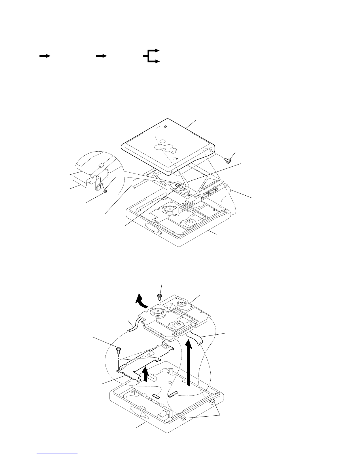
3-1. “LID ASSY, UPPER”, HOLDER ASSY
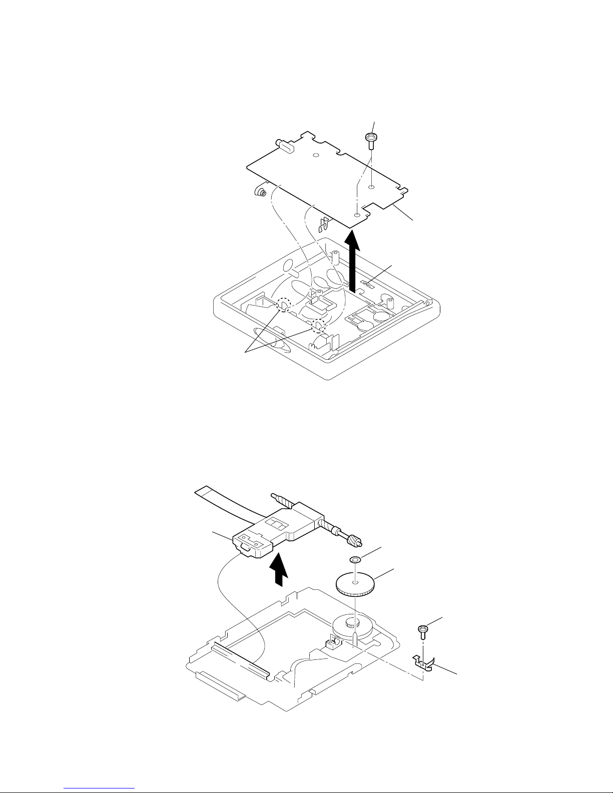
3-2. MECHANISM DECK
• The equipment can be removed using the following procedure.
1
Screws (1.4),MI
Case ASSY
3
Lid ASSY , Upper
5
Holder ASSY
Holder ASSY
Reinforcement
Spring (POP/L)
4
Move it away
from projection
4
Move it away
from projection
2
Move it away
from projection
7 Screws, tapping (1.7)
Case ASSY
Mechanism deck
Reinforcement
3 Claw
2
4
8
1 Screw (MD), step
5 Motor flexible board
6 OP flexible board
Optical pick-up ASSY
Set
“Lid ASSY, Upper”,
Holder ASSY
Mechanism deck
Main board
Note : Holder ASSY installation
1. Attach the holes on Holder ASSY to the projections on right and left sides.
2. Attach Spring (POP/L) as shown in the figure.
5
MZ-E300
3-3. MAIN BOARD
3-4. OPTICAL PICK-UP ASSY
1 Screws, tapping (1.7)
2 Claw
3
Main boar
d
Knob (HOLD)
3
Screw (MI 1.4)
4
Spring, thrust deten
t
1
Washer
2
Gear (SA)
5
Optical pick-up ASSY
(LCX-4E)
Note : On installation of main board, adjust the position of
both switch (S809) and knob (HOLD).

6
MZ-E300
3 In the normal mode, operate the keys on the set and those on the
remote control as specified below:
Turn on HOLD switch on the set. Holding down x (STOP)
key on the set, press the keys on the remote control in the
following sequence:
> N t > N t . t . t > N
t . t > N t . t X t X
R_VDD
R_DATA
R_KEY
R_GND
TP804
TP803
TP802
TP801
TP806
TP805
TP951
MAIN BOARD
(SIDE A)
JACK: 1-793-288-61
4321
12 34
4-1. GENERAL
• When entered in the TEST MODE, this set provides the Overall
Adjustment mode which allows CD and MO discs to be automatically adjusted. In the Overall Adjustment mode, performs
adjustments in sequence automatically, and displays the faulty
location if any fault is found. In the Manual mode, selected adjustments can be performed automatically.
• Operations in the Overall Adjustment mode can be performed
either via the main unit, or the keys of a remote control unit.
Note that this device does not include a remote control unit.
Therefore, since no connection terminals for a remote control
are provided either, a connection device must be used in order
to allow a suitable remote control unit to be connected.
Connection
Following parts are required
Remote commander: RM-MZ2N (1-418-493-71)
After RM-MZE1 applicable to 2.4V
(Not applicable to remote commanders
before RM-MZE1).
Jack: 7 poles jack for phones/remote commander (1-793-288-61)
SECTION 4
TEST MODE
Lead wires: 4 leads
4-2. SETTING THE TEST MODE
4-2-1. How to set the TEST MODE
To set the TEST MODE, three methods are available.
1 Solder bridge and short BP801 (TEST) on the main board.
Then turn on the power.
C810
C
8
R907
R803
R82
R830
C806
C805
X801
C8
0
FB801
15
20
21
IC501
TP809
BP801
(TEST)
TP808
TP816
OPEN : Normal mode
SHORT : Test mode
BP801
MAIN BOARD (SIDE A)
TP804
TP804 TP805
TP803
TP802
TP801
TP806
TP805
TP951
MAIN BOARD
(SIDE A)
2 Using a pair of tweezers or similar tool short-circuit TP804 and
TP805 on the main board and turn on the power.
7
MZ-E300
888:88
130
u
F
1SHUFF
AVLS BASS
All on
All off
Microprocessor
version
display
888
u
008 V1.300
F
1SHUFF PGM
SOUND 1 2 BASS 1 2
All on
All off
Microprocessor
version
display
The remote control display varies with the type of
remote control unit used.
(Example shown: RM-MC10L)
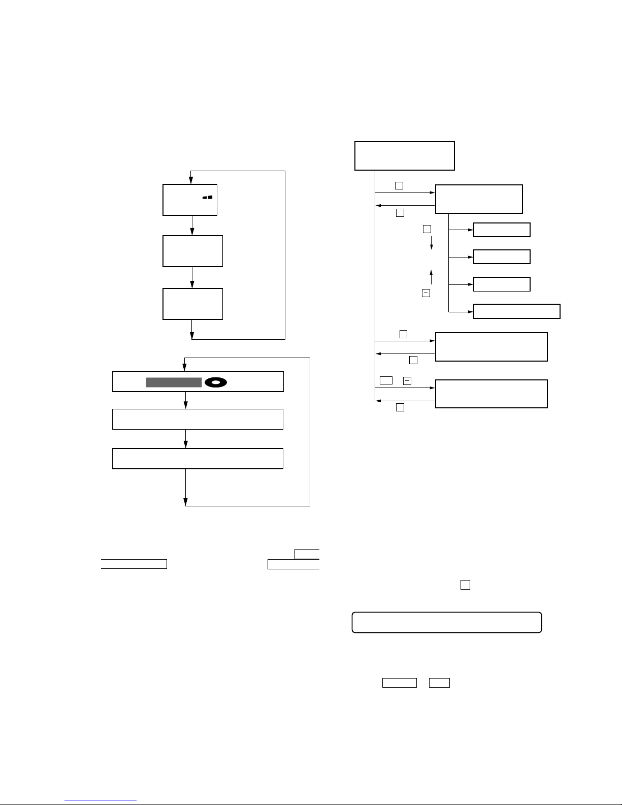
4-2-2. Operations when the TEST MODE is set
When the TEST MODE is entered, the system switches to the display check mode within the TEST MODE. From this mode, the
other Test modes can be accessed.
When the TEST MODE is set, the LCD repeats a cycle of the following displays:
Main unit LCD
4-4. MANUAL MODE
4-4-1. Outline of the function
The Manual mode is designed to perform adjustments and
operational checks on the set’s operation according to each
individual function.
Usually, no adjustments are made in this mode.
However, the Manual mode is used to clear the memory before
performing automatic adjustments in the Overall Adjustment mode.
* Manual mode operation can only be performed via the remote
control unit.
Use the connection tool to connect the remote control unit. The
display of the main unit shows “Adj”.
4-4-2. How to set the Manual mode
1. Set the TEST MODE and press + key to set the Manual mode.
Remote control LCD display
000 AAAS CC
Test Mode
(Display Check Mode)
Manual Mode
(Remote control only)
Servo Mode
Audio Mode
Power Mode
OP Alignment Mode
key
key
+
key
+
key
x
x
key
key
.
or
Overall Adjustment Mode
x
Press and hold
down
keyRelease
x
key
Display segment check mode
(Main unit only)
2. When the test mode display shows “100”, “200”, “300”, “500”,
“600”, “700”, “800”, or “900”, the optical pickup can be moved
inside and outside of the SLED perimeter by continuously pressing the ( > N or . keys on the main unit.
• The current display is retained as long as either the PLAY
MODE/DISPLAY key on the main unit or the PLAY MODE
key on the remote control unit is pressed and held.
4-2-3. How to release the TEST MODE
When method 1 was used:
Turn off the power and open the solder bridge on BP801 on the
main board.
Note: The solder should be removed clean. The remaining solder
may make a short with the chassis and other part.
When method 2 or 3 was used:
Turn off the power.
Note: If electrical adjustment (see page 8) has not been finished
completely, always start in the test mode. (The set cannot
start in normal mode)
4-3. TEST MODE STRUCTURE
* Manual mode operation can only be performed via the remote
control unit.
Use the connection tool to connect the remote control unit. The
display of the main unit shows “Adj”.
Remote control LCD
Ver 1.2 2001.12
8
MZ-E300
Note: In the Power mode, the item title display is only displayed.
5. To terminate the Manual mode and return to the TEST MODE,
press x key.
4. During each test mode, the display is changed from one to
another each time DISPLAY key is pressed (Remote control
only).
4-5. OVERALL ADJUSTMENT MODE
4-5-1. Outline of the function
This mode is designed to adjust the servo system automatically by
going through all the adjustment items.
Usually, this mode is used to perform automatic adjustments when
servicing the set.
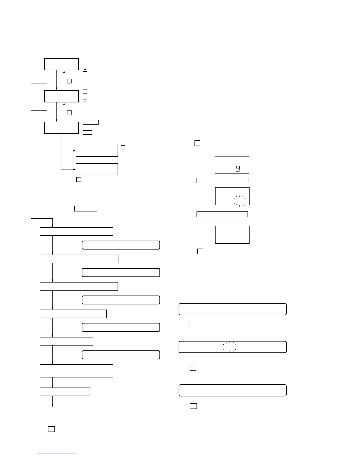
4-6. NV RESET
Power: Connect the battery terminals to a stable DC 1.5V power
supply, or insert fresh batteries (size “AA”, IEC “LR6”).
Two different methods apply for NV reset, depending on whether
the main unit or a remote control unit is used.
NV reset via main unit
1. Enter test mode.
2. Use the – key or the . key to set the device to Overall
Adjustment mode.
021 AAAS CC
021 AAAS CC
Flash CC
021 AAAS CC
3. Each test item is assigned with a three-digit item number. The
100th place is a major item, 10th place is a middle item, and unit
place is a minor item.
Change Major
Item
Change Middle
Item
Change Minor
Item
Change Adjustment
Value
Write Adjustment
Value
.
key : 100th place of mode number
increase
+
key : 100th place of mode number
decrease
key : 10th place of mode number
increase
+
key : 10th place of mode number
decrease
key : Up
+
key : Down
key : When adjusted value is changed :
Adjusted value is written.
When adjusted value is not changed :
That item is adjusted automatically.
keykey
x
key
x
> N
key
> N
key : Unit place of mode number
increase
key : Unit place of mode number
decrease
> N
X
011 XXXSXX
Address Value & Adjustment Value
LCD display
011 XX BXX
Block Error Value & Adjustment Value
LCD display
011 XX AXX
ADIP Error Value & Adjustment Value
LCD display
011 XXXJXX
Jitter Value & Adjustment Value
LCD display
731 XX VXX
Power Adjustment Value
LCD display
Memory Monitor Mode
XXX: Each Value
XX: Adjustment Value
for Item number
After the voltage indicator appears,
press the DISPLAY key twice.
* Functions are displayed,
but cannot be used via
this unit.
3. Press the PLAY MODE/DISPLAY key. “CL” starts to flash.
ASS
4. Press the PLA Y MODE/DISPLAY key once more. “CL” stops
flashing and remains lit, thus concluding NV reset.
5. Press the x key to return to test mode.
NV reset via remote control
1. Set the TEST MODE.
2. Set the Manual mode and set the item No. 021, Reset NV.
LCD display
AdJ
cL
AdJ
cL
3. Press X key on the remote control.
LCD display
4. Press X key on the remote control again.
LCD display
5. Press x key to terminate the Manual mode and return to the
TEST MODE.
9
MZ-E300
4-6-1. Electrical offset adjustment method
Note: Doing adjustment by the state that a disc does not enter.
1. Confirm the power voltage is 1.5V.
2. Set to the test mode.
3. Press the – key of main unit activates the overall adjustment
mode.
Main unit LCD display
4. Press the + key.
Main unit LCD display
5. Press the + key once more. Adjustment is complete when the
adjustment value appears in the “XX” position.
ASS
TEST MODE
(Display Check Mode)
Overall Adjustment
Title Display(ASSY**)
CD overall
Adjustment
.
key
.
VOL – key or key
key
x
MO overall
Adjustment
> N
key
> N
key
key
x
Electrical offset
Adjustment key
VOL + key
key
x
key
x
NV reset
PLAY MODE/DISPLAY key
035:
XX
Microprocessor Version 1.10
1 Clear NV.
2 Electric offset adjustment.
3 Rewriting of RAM 633h
1. switch to manual mode No. 100.
2. Press the DISPLAY key on the remote control unit 6 times
consecutively to enter RAM mode.
3. Change the RAM address to 633h.
Use the following keys on the remote control unit to change
the digits of the RAM address:
“The DISPLAY key for the first digit (hundreds), the x key
for the second digit (tens) and the >B key or the .
key for the third digits (units).”
4. Use the + and – keys on the remote control unit to set the
adjustment value of No.633h to 03h and press once the pause
key on the remote control unit to write this value to NV.
“(If NV is cleared, the value is 00h.)
5. Press the DISPLAY key once more to change the display
to “address and adjustment value display”.
6. Switch to the overall adjustment.
4 CD overall adjustment * (Not to turn off the power between the
items 3 and 4 .)
4-6-2. Display segment check mode
1. Enter test mode. Display continuously alternates between the
following three conditions: entire LCD is lit, entire LCD is extinguished, version info is shown, and so on.
2. Press and hold the x key on the main unit to enter display
segment check mode.
* Should segments not be displayed correctly at this point, a short-
circuited COM terminal and/or SEG terminal on the microprocessor chip (IC801) are possible causes.
3. Display returns to condition “1” as soon as the x key is released.
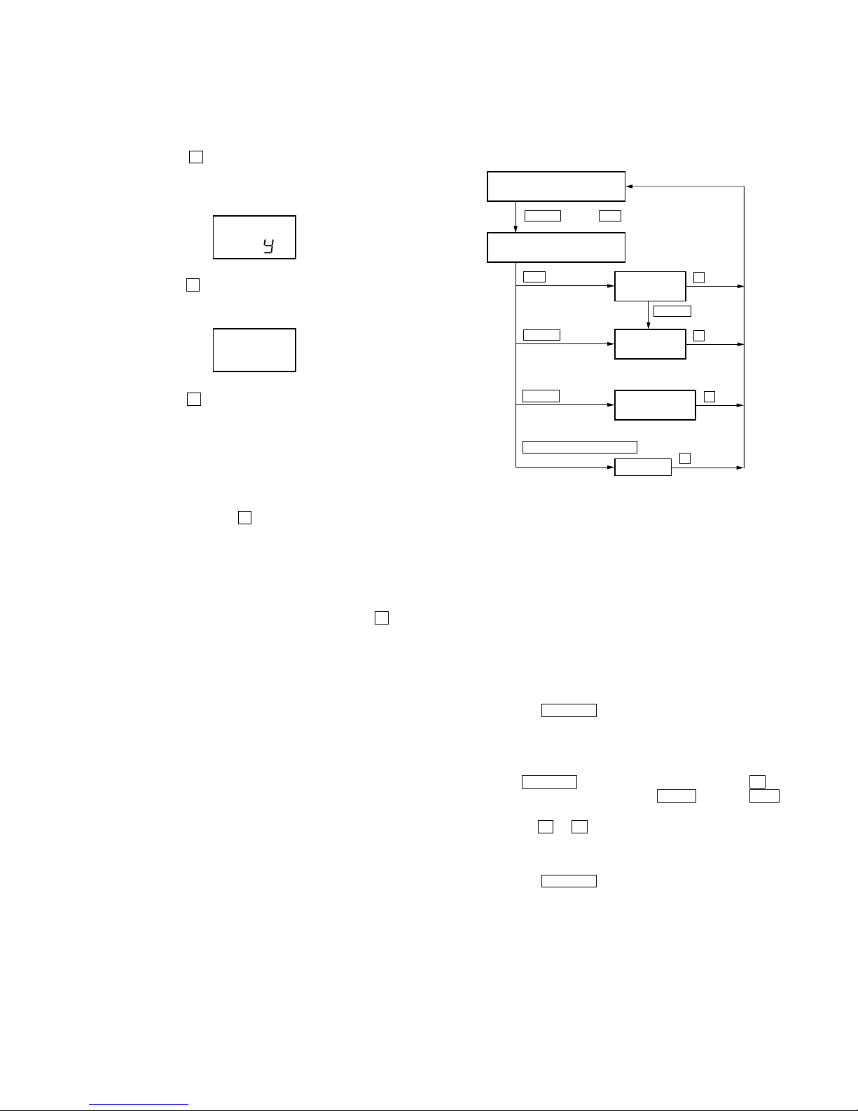
4-7. OVERALL ADJUSTMENT MODE
4-7-1. Overall adjustment mode structure
Perform overall adjustments according to the following procedures
(procedures may differ depending on the microprocessor chip
version used).
For Ver. 1.10, if it is no good in the overall adjustment, please
repeat the overall adjustment several times.
10
MZ-E300
5 Rewriting of the adjustment value.
1.After CD overall adjustment, switch to manual mode No. 321
in the condition the disc is in.
2.Press – key on the remote control unit to set 1 step down the
adjustment value of No. 321, and press the pause key on the
remote control unit to write this value to NV.
3.Press the >B key on the remote control unit to switch to
manual mode No. 323.
4.Press the pause key on the remote control unit to set to the
automatic adjustment.
During adjusting automatically, the adjustment value turns on
and off, so wait for the time the adjustment value is on.
5.Press the >B key on the remote control unit to switch to
manual mode No. 345.
6.Note down the current adjustment value of No. 345 (value X).
Use the + and – keys on the remote control unit to set the
adjustment value of No. 345 to the value (Y) determined by
the formula below, and press the pause key on the remote
control unit to write this value to NV.
Formula: X x 1.18 = Y
* Since X and Y are 2’sC, attention must be paid to codes.
And the maximum value of Y must be 7Fh. (Never set it to
the negative value.)
Example: Since X = 2Bh, Y = 2Bh x 1.18 = 33h
6 Change the disc to MO overall adjustment disc (GA1 disc).
Switch to manual mode No.114.
Press the pause key on the remotecontrol unit to set to the
automatic adjustment.
After adjustment, pull out the battery from the set to turn off
the power.
Then insert the battery again.
7 MO overall adjustment.
Microprocessor Version 1.20 and higher
1 Clear NV.
2 Electric offset adjustment.
3 CD overall adjustment.
4 Rewriting of the adjustment value.
1.After CD overall adjustment, switch to manual mode No. 321
in the condition the disc is in.
2.Press – key on the remote control unit to set 1 step down the
adjustment value of No. 321, and press the pause key on the
remote control unit to write this value to NV.
3.Press the >B key on the remote control unit to switch to
manual mode No. 323.
4.Press the pause key on the remote control unit to set to the
automatic adjustment.
During adjusting automatically, the adjustment value turns on
and off, so wait for the time the adjustment value is on.
5.Press the >B key on the remote control unit to switch to
manual mode No. 345.
6.Note down the current adjustment value of No. 345 (value X).
Use the + and – keys on the remote control unit to set the
adjustment value of No. 345 to the value (Y) determined by
the formula below, and press the pause key on the remote
control unit to write this value to NV.
Formula: X x 1.18 = Y
* Since X and Y are 2’sC, attention must be paid to codes.
And the maximum value of Y must be 7Fh. (Never set it to
the negative value.)
Example: Since X = 2Bh, Y = 2Bh x 1.18 = 33h
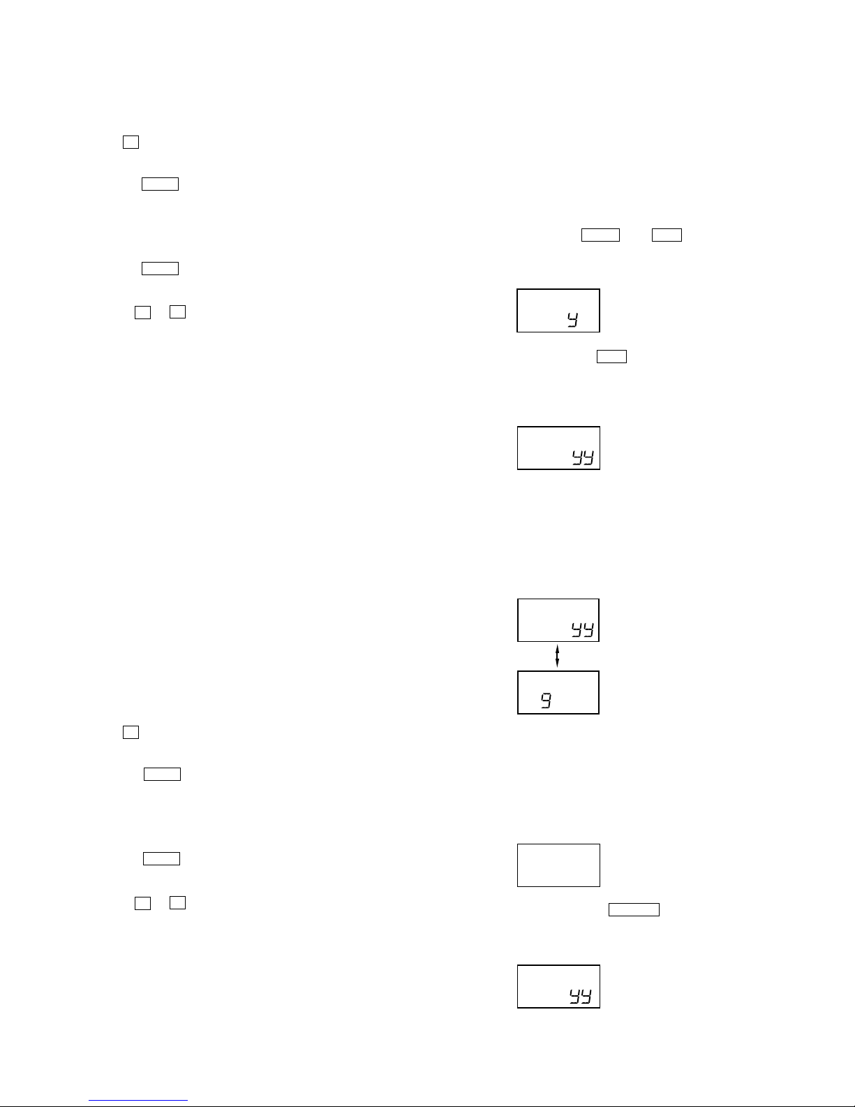
4-7-2. Overall CD and MO adjustment method
1. Set the TEST MODE and press VOL – key or . key to set
the Overall Adjustment mode.
Main unit LCD display
2. Insert CD disc in the set, and press . key to set the Overall
CD Adjustment mode.
Automatic adjustments are made.
Main unit LCD display
XXX: Item No. for which an adjustment is being executed.
YY: Adjustment Value
3. If NG in the overall CD adjustments, return to Reset NV and
perform from the electrical offset adjustment again.
The NG item and “ng” alternately flash on the main unit LCD
display.
XXX: NG item No.
YY: Adjustment Value
4. If OK through the overall CD adjustments, then perform overall
MO adjustments.
Main unit LCD display
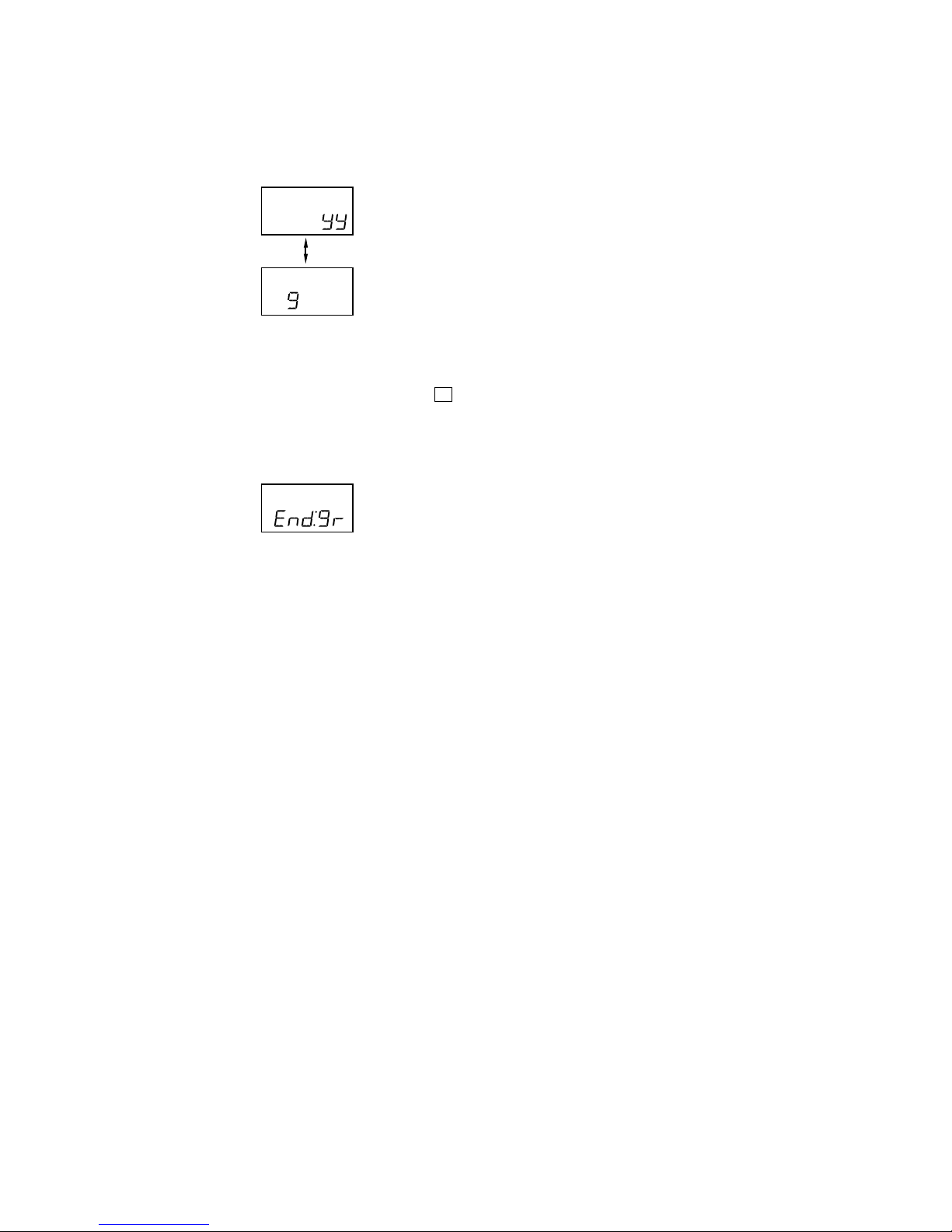
5. Insert MO disc in the set, and press > N key to set the
Overall MO Adjustment mode. Automatic adjustments are made.
Main unit LCD display
XXX: Item No. for which an adjustment is being executed.
YY: Adjustment Value
XXX:
ASS
XXX:
n
End:cd
XXX:
5 Change the disc to MO overall adjustment disc (GA1 disc).
Switch to manual mode No.114.
Press the pause key on the remotecontrol unit to set to the
automatic adjustment.
After adjustment, pull out the battery from the set to turn off
the power.
Then insert the battery again.
6 MO overall adjustment.
Ver 1.1 2001.03
11
MZ-E300
6. If NG in the overall MO adjustments, return to Reset NV and
perform the adjustment again.
The NG item and “ng” alternately flash on the main unit LCD
display.
XXX: NG item No.
YY : Adjustment Value
7. If OK through the overall MO adjustments, press x key to
return to the TEST MODE and terminate the Overall Adjustment mode.
Main unit LCD display
XXX:
n
 Loading...