

Page 1
3-865-344-11(2)
LCD Data Pr ojector
Operating Instructions
VPL-X2000U
VPL-X2000E
VPL-X2000M
GB
Page 2
English
WARNING
To prevent fire or shock hazard, do not
expose the unit to rain or moisture.
To avoid electrical shock, do not open the
cabinet. Refer servicing to qualified
personnel only.
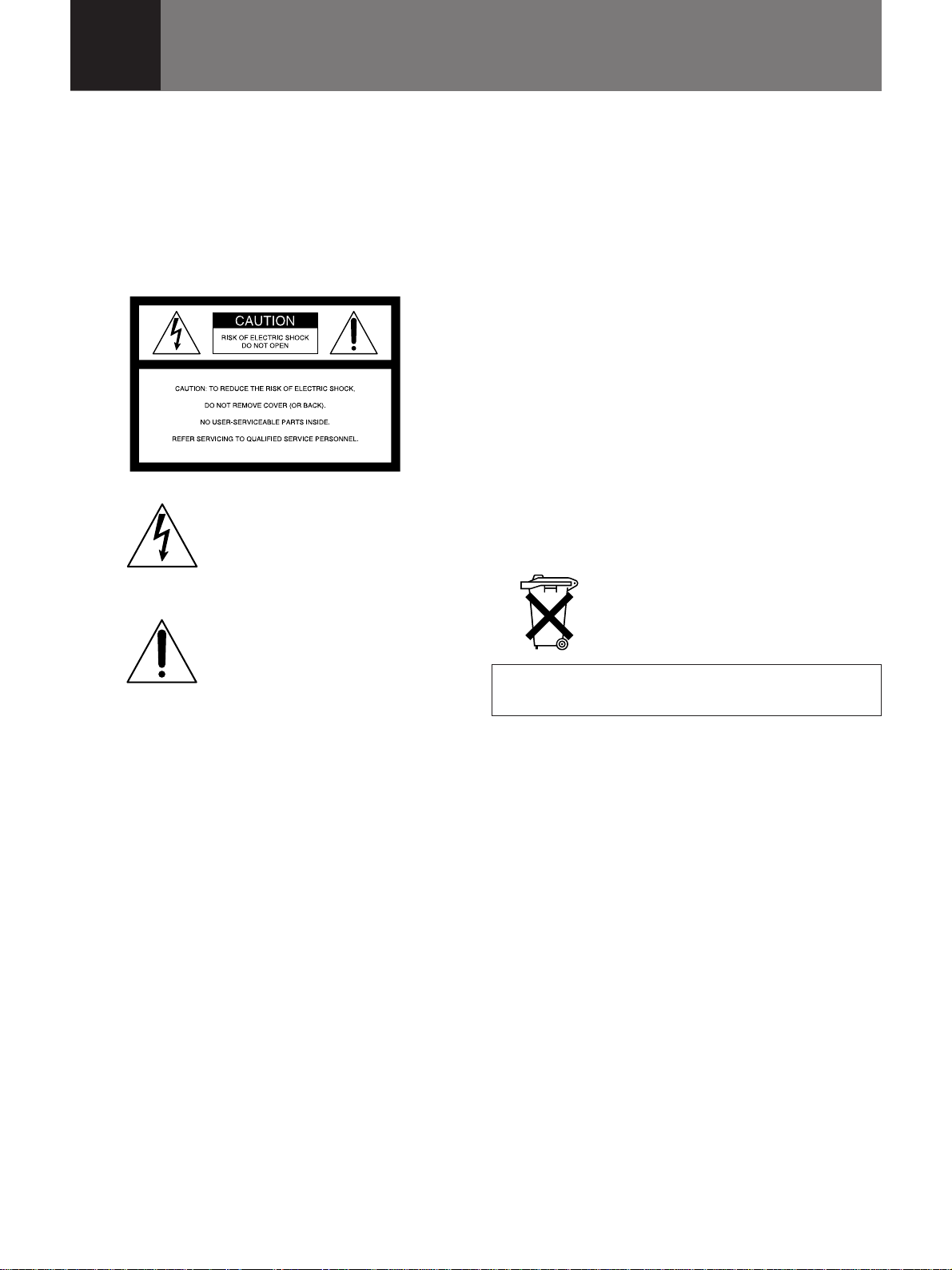
This symbol is intended to alert the
user to the presence of uninsulated
“dangerous voltage” within the
product’s enclosure that may be of
sufficient magnitude to constitute a
risk of electric shock to persons.
This symbol is intended to alert the
user to the presence of important
operating and maintenance (servicing)
instructions in the literature
accompanying the appliance.
For the customers in the United Kingdom
WARNING
THIS APPARATUS MUST BE EARTHED
IMPORTANT
The wires in this mains lead are coloured in accordance with
the following code:
Green-and-yellow : Earth
Blue : Neutral
Brown : Live
As the colours of the wires in the mains lead of this
apparatus may not correspond with the coloured markings
identifying the terminals in your plug proceed as follows:
The wire which is coloured green-and-yellow must be
connected to the terminal in the plug which is marked by the
letter E or by the safety earth symbol Y or coloured green or
green-and-yellow.
The wire which is coloured blue must be connected to the
terminal which is marked with the letter N or coloured black.
The wire which is coloured brown must be connected to the
terminal which is marked with the letter L or coloured red.
Voor de klanten in Nederland
Bij dit produkt zijn batterijen geleverd.
Wanneer deze leeg zijn, moet u ze niet
weggooien maar inleveren als KCA.
The socket-outlet should be installed near the equipment
and be easily accessible.
For the customers in the USA
This equipment has been tested and found to comply with
the limits for a Class A digital device, pursuant to Part 15 of
the FCC Rules. These limits are designed to provide
reasonable protection against harmful interference when the
equipment is operated in a commercial environment. This
equipment generates, uses, and can radiate radio frequency
energy and, if not installed and used in accordance with the
instruction manual, may cause harmful interference to radio
communications. Operation of this equipment in a residential
area is likely to cause harmful interference in which case the
user will be required to correct the interference at his own
expense.
You are cautioned that any changes or modifications not
expressly approved in this manual could void your authority
to operate this equipment.
For the customers in Canada
This Class A digital apparatus complies with Canadian ICES-
003.
2 (GB)
Page 3
Table of Contents
Overview
Setting up and projecting
Adjustments and settings
using the menu
Precautions ............................................................... 4 (GB)
Features..................................................................... 6 (GB)
Location and Function of Controls......................... 8 (GB)
Front .............................................................................. 8 (GB)
Rear ............................................................................. 12 (GB)
Remote Commander ................................................... 14 (GB)
Precautions on Installation.................................... 18 (GB)
Installing the Projector on the Floor..................... 19 (GB)
Connecting with a Computer or a VCR ................ 20 (GB)
Projecting ................................................................ 21 (GB)
Using the Menu....................................................... 24 (GB)
The PICTURE CTRL Menu ..................................... 25 (GB)
The INPUT SETTING Menu .................................... 27 (GB)
The SET SETTING Menu ........................................ 30 (GB)
The SIGNAL SELECT Menu ................................... 32 (GB)
GB
English
Installation/connection
examples/Index number setting
Installation Examples............................................. 33 (GB)
Connection Examples ............................................ 42 (GB)
Setting the Index Numbers .................................... 45 (GB)
Maintenance
Maintenance............................................................ 48 (GB)
Troubleshooting ..................................................... 50 (GB)
Others
Specifications ......................................................... 52 (GB)
Index ........................................................................ 59 (GB)
About the Picture Size................................................. 33 (GB)
Floor Installation ......................................................... 34 (GB)
Ceiling Installation...................................................... 38 (GB)
Connecting 15k RGB/Component Equipment............ 42 (GB)
Connecting the Switcher ............................................. 43 (GB)
Confirming the System Construction.......................... 44 (GB)
Replacing the Lamp .................................................... 48 (GB)
Cleaning the Air Filter................................................. 49 (GB)
3 (GB)
Page 4

Precautions
On safety
•Check that the operating voltage of your unit is identical with the voltage
of your local power supply. If voltage adaptation is required, consult with
qualified Sony personnel.
•Should any liquid or solid object fall into the cabinet, unplug the unit and
have it checked by qualified Sony personnel before operating it further.
•Unplug the unit from the wall outlet if it is not to be used for several
days.
•To disconnect the cord, pull it out by the plug. Never pull the cord itself.
•The wall outlet should be near the unit and easily accessible.
•The unit is not disconnected from the AC power source (mains) as long
as it is connected to the wall outlet, even if the unit itself has been turned
off.
•Do not look into the lens while the lamp is on.
•Do not place your hand or objects near the ventilation holes — the air
coming out is hot.
On installation
On illumination
•When the projector is mounted on the ceiling, the Sony PSS-2000
Projector Suspension Support must be used for installation.
•Allow adequate air circulation to prevent internal heat build-up. Do not
place the unit on surfaces (rugs, blankets, etc.) or near materials (curtains,
draperies) that may block the ventilation holes. Leave space of more than
30 cm (11
room heat rises to the ceiling; check that the temperature near the
installation location is not excessive.
•Do not install the unit in a location near heat sources such as radiators or
air ducts, or in a place subject to direct sunlight, excessive dust or
humidity, mechanical vibration or shock.
•To obtain the best picture, the front of the screen should not be exposed
to direct lighting or sunlight.
•Ceiling-mounted spot lighting is recommended. Use a cover over
fluorescent lamps to avoid lowering the contrast ratio.
•Cover any windows that face the screen with opaque draperies.
•It is desirable to install the projector in a room where floor and walls are
not of light-reflecting material. If the floor and walls are of reflecting
material, it is recommended that the carpet and wall paper be changed to
a dark color.
7
/8 inches) between the wall and the projector. Be aware that
4 (GB)
Page 5
On preventing internal heat build-up
•After turning off the power, the cooling fan runs for about six minutes
while the ON indicator flashes in green. The indicator flashes quickly for
one minute. During that time, you will not be able to turn the power back
on with the ON key.
Caution
The projector is equipped with ventilation holes (intake) at the bottom/
front side and ventilation holes (exhaust) at the left/right side.
Do not block or place anything near these holes, or internal heat build-up
may occur, causing picture degradation or damage to the projector.
On cleaning
•To keep the cabinet looking new, periodically clean it with a soft cloth.
Stubborn stains may be removed with a cloth lightly dampened with a
mild detergent solution. Never use strong solvents, such as thinner,
benzene, or abrasive cleansers, since these will damage the cabinet.
•Avoid touching the lens. To remove dust on the lens, use a soft dry cloth.
Do not use a damp cloth, detergent solution, or thinner.
•Clean the air filter in every 100 hours.
Overview
On repacking
•Save the original shipping carton and packing material; they will come in
handy if you ever have to ship your unit. For maximum protection,
repack your unit as it was originally packed at the factory.
5 (GB)
Page 6

Features
High brightness, high picture quality
• High brightness
Adopting four 120 W UHP lamps and newly developed optical system
povides high brightness (light output 2400 of ANSI lumen) and excellent
uniformity on the picture.
• High resolution
Thanks to use of three 1.8-inch XGA
pixels, the projector can project the sharp picture with the resolution of
1024 × 768 pixels.
• DRC (Digital Reality Creation)
The DRC technology allows you to obtain a finer, more detailed picture
with four-times higher density than the conventional video picture.
Accepts various input signals
This projector has a built-in high performance scan converter which
converts the input signals to display the 15 k RGB, HDTV, VGA
SVGA
video signals of the composite, S video and component.
System expandability and versatility
The projector has RS-232C/422A/PJ COM interface connectors for
communication.
By combining the interface boards and signal interface switcher (not
supplied), VPL-X2000U/X2000E/X2000M projection systems can be
greatly expanded. This projector also has the group and device index
functions for using multiple projectors in one system.
1)
panels with approximately 790,000
1)
1)
, XGA1), SXGA1) and UXGA1) (fV = 60 Hz) signals as well as the
,
Easy and flexible setup
• Sony’s original APA (Auto Pixel Alignment) function
You can obtain the clearest picture automatically by simply pressing the
APA key when the signal is input from a computer.
• Easy setup with external equipment
This projector has 39 preset data for input signals in the memory. You can
get a picture properly on the screen by connecting equipment and pressing
the APA key.
..........................................................................................................................................................................................................
1) VGA, SVGA, XGA, SXGA and UXGA are the registered
trademarks of the International Business Machines
Corporation, U.S.A.
6 (GB)
Page 7

• Flexible setup
The lens shift function allows you to install the projector in a wide range
of locations, without worrying about keystone distortion (the picture going
out of square). The power focus and power zoom functions also let you
change the size of the projection screen without having to move the
projector.
• Stack installation
Thanks to the lens shift function, up to three projectors can be stacked,
which improves the brightness of the image.
• Fail safe function
The projector uses four lamps for light source. Even if one of them has
burnt out, you can still use the projector. If two lamps have burnt out, the
projector will automatically enter into standby mode.
7 (GB)
Page 8
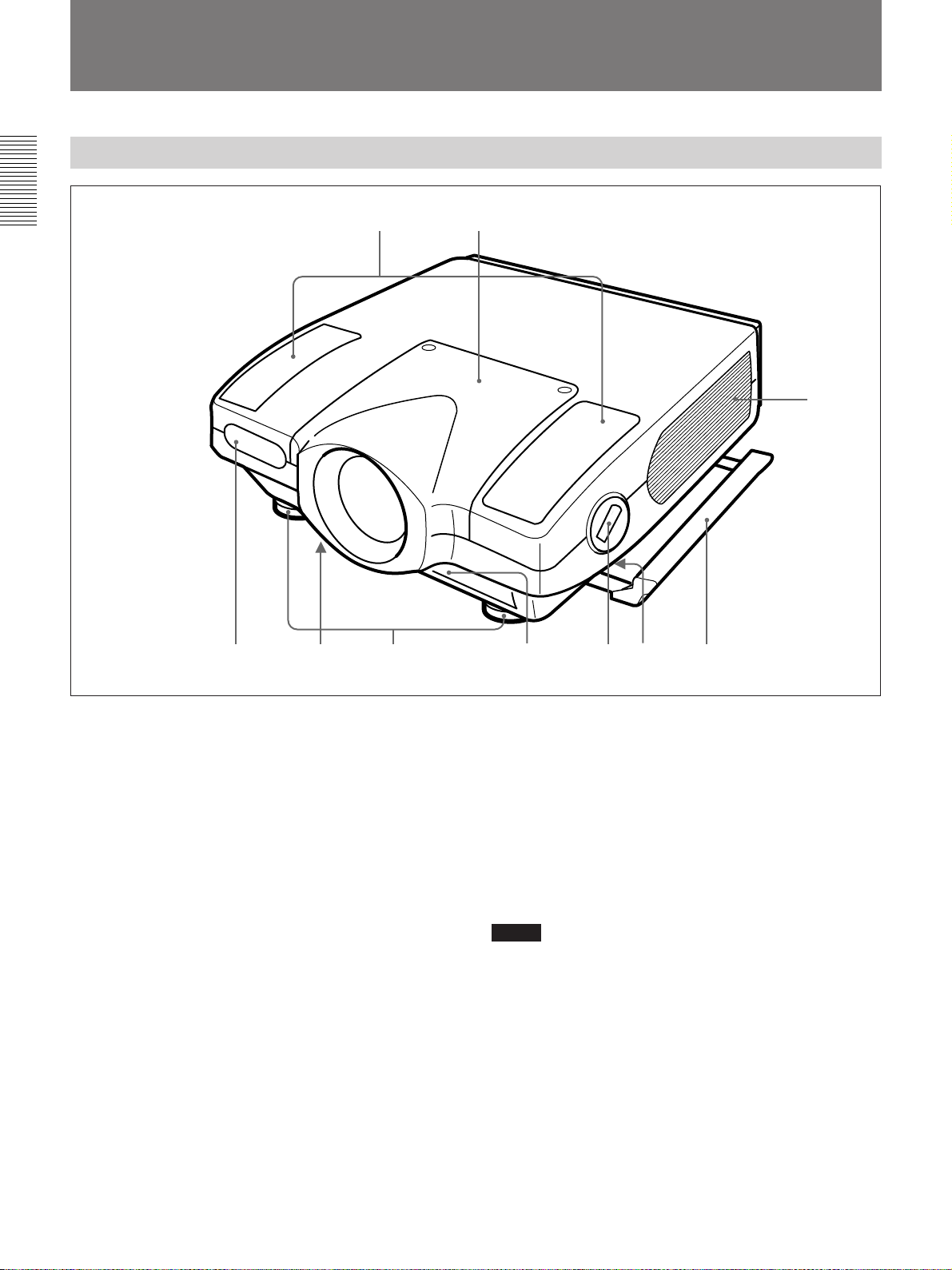
Location and Function of Controls
Front
12
!º
379
1 Lens mount part
When attaching the optional lens, consult with the
Sony service personnel.
2 Speaker
3 Front remote control detector
4 Bottom ventilation holes (intake)
Do not block the holes.
5 Adjusters
Use the adjusters to keep the projector level if it is
installed on an uneven surface.
6 Front ventilation holes (intake)
Do not block the holes.
7 Adjuster button and lever
Press the button to raise the lever for adjusting the
height of the adjuster.
8546
8 Handle lever (left and right sides)
Use the lever for putting away the carrying handle.
9 Carrying handle (left and right sides)
Pull out the handle for carrying the projector.
!º Left and right side ventilation holes (exhaust)
Do not place anything within the 30 cm (11
range from these holes or block them.
Notes
•Do not block the ventilation holes, or internal heat
build-up may occur, causing fire or damage to the
projector.
•Do not place anything near the ventilation holes or
touch these holes as the temperature will be very
high.
7
/8 inches)
8 (GB)
Page 9
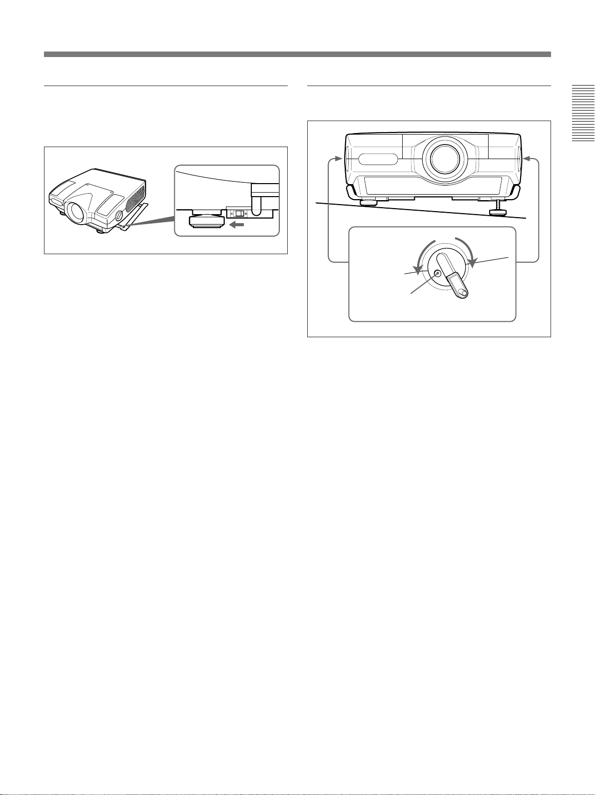
Using the carrying handles
Pull out to use for carrying the projector. To put away
the handle, slide the handle lever forward.
Using the adjusters
To lower the
projector
To raise the
projector
Adjuster button
1 Press the adjuster button.
The adjuster lever comes out.
2 Turn the lever to adjust the height so that the
projector becomes level.
3 Replace the adjuster lever after use.
9 (GB)
Page 10
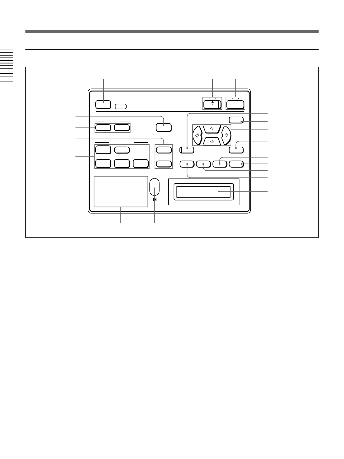
Location and Function of Controls
Control panel
123
LIGHT
4
5
6
VIDEO
7
INPUT A INPUT B INPUT C
POWER SAVING
COVER FAIL
HIGH TEMP
RESET
+
MUTING
PIC AUDIO
INPUT SELECT
SELECT
FAN FAIL
SYS SET
APA
VOLUME
LAMP FAIL
12
34
89
1 ON key and indicator
Press to turn on the power of the projector.
The indicator lights when the key is pressed.
The indicator flashes for about six minutes after the
power is turned off by pressing the STANDBY key, as
the fan runs for six minutes to cool down the inside of
the projector. The indicator flashes quickly for one
minute, during which you will not be able to turn the
power back on with the ON key.
2 STANDBY key and indicator
Press to make the projector enter standby mode.
The indicator lights to indicate that the projector is in
standby mode.
3 LIGHT key
Illuminates the key indicators in orange when the
projector is turned on. Illuminates the indicators for the
relative keys in green when this key is pressed during
operation. Press again to turn off the indicators.
STANDBY
ON
!•
MENU
!¶
!§
!∞
+
ENTERRESET
!¢
–
PATTERN
ZOOM SHIFT FOCUS
!£
!™
!¡
!º
4 APA (Auto Pixel Alignment) key
Adjusts the position of the picture on the screen
automatically so that the picture is clearly visible when
the signals are input from a computer.
5 MUTING keys
Cut off the picture or sound temporarily.
PIC: Press to cut off the picture. Press again to
restore the picture.
AUDIO: Press to cut off the sound output from the
speakers or the AUDIO OUT jacks. Press again or
press the VOLUME + key to restore the sound.
6 VOLUME +/– keys
Adjust the volume of the built-in speakers and output
level of the AUDIO OUT jacks.
+ : Increases the volume.
– : Decreases the volume.
Pressing this key and the RESET key simultaneously
has the same function as the SYS SET key on the
Remote Commander. Use when the PC-3000 signal
interface switcher is used in the system or the system
connections are changed.
10 (GB)
Page 11
7 INPUT SELECT keys
Select the input signal.
VIDEO: Selects the video signal input from the
VIDEO or S VIDEO connectors and the audio
signal input from the AUDIO IN L/R jacks. To
switch the S VIDEO and VIDEO connectors, use
the SELECT key.
SELECT: Each time you press this key, the input
video signal is switched between the VIDEO and
S VIDEO connectors.
INPUT A: Selects the audio and video signals input
from the INPUT A connectors.
INPUT B: Selects the signal input from the
connectors on the optional interface board which
is installed in the INPUT B section. When the
IFB-12A interface board is installed and the
output mode is selected on the IFB-12A, the key
does not function.
INPUT C: Selects the signal input from the
connectors on the optional interface board which
is installed in the INPUT C section.
Note on the VPL-X2000E model
The optional IFB-X2000E interface board is required
to select VIDEO.
8 Indicators
POWER SAVING: Lights when the projector is in
power saving mode. When POWER SAVING in
the SET SETTING menu is set to ON, the
projector goes into the power saving mode if no
signal is input for 10 minutes. Although the lamp
goes out, the cooling fan keeps running. In the
power saving mode, only the STANDBY key
functions for the first 30 seconds. The power
saving mode is canceled when a signal is input or
any key is pressed.
COVER FAIL: Lights when the lamp cover or air
filter cover is not secured firmly.
FAN FAIL: Lights when the fan is broken.
HIGH TEMP: Lights when temperature inside the
projector becomes unusually high.
LAMP FAIL: When the lamp life has reached the
end, the indicator of that lamp lights.
9 Rear remote control detector
!º Message display window
Displays the signal status, timer and error messages
about the input signals.
!¡ PATTERN key
Displays a HATCH pattern on the screen for focus,
zoom, and shift adjustments. Press again to turn off the
HATCH pattern.
!™ ZOOM key
Enters the zoom adjustment mode. When the key is
pressed, the relative keys light in green.
Next adjust the zoom using the arrow keys.
V: Enlarges the picture size.
v: Reduces the picture size.
Note
If the VPLL-2075, VPLL-2014 or VPLL-2009
optional lens is installed, you cannot adjust the zoom.
!£ FOCUS key
Enters the focus adjustment mode. When the key is
pressed, the relative keys light in green.
Next adjust the focus using the arrow keys.
V: Focuses on a forward picture.
v: Focuses on a picture further back.
!¢ SHIFT (lens shift) key
Enters the shift adjustment mode. When the key is
pressed, the relative keys light in green.
Next adjust the vertical position of the picture using
the arrow keys.
V: Moves the picture upward.
v: Moves the picture downward.
!∞ ENTER key
Stores the settings in the menu.
!§ Arrow keys (V/v/B/b)
Used to adjust the picture after pressing the ZOOM,
FOCUS or SHIFT key. Also used to move the cursor
or adjust the value in the menu.
!¶ MENU key
Displays the menu on the screen. When the key is
pressed, the relative keys light in green.
Press again to turn off the menu.
!• RESET key
Resets the adjusted value of an item to its factory
preset value. This key functions when the menu or a
setting item is displayed on the screen.
11 (GB)
Page 12
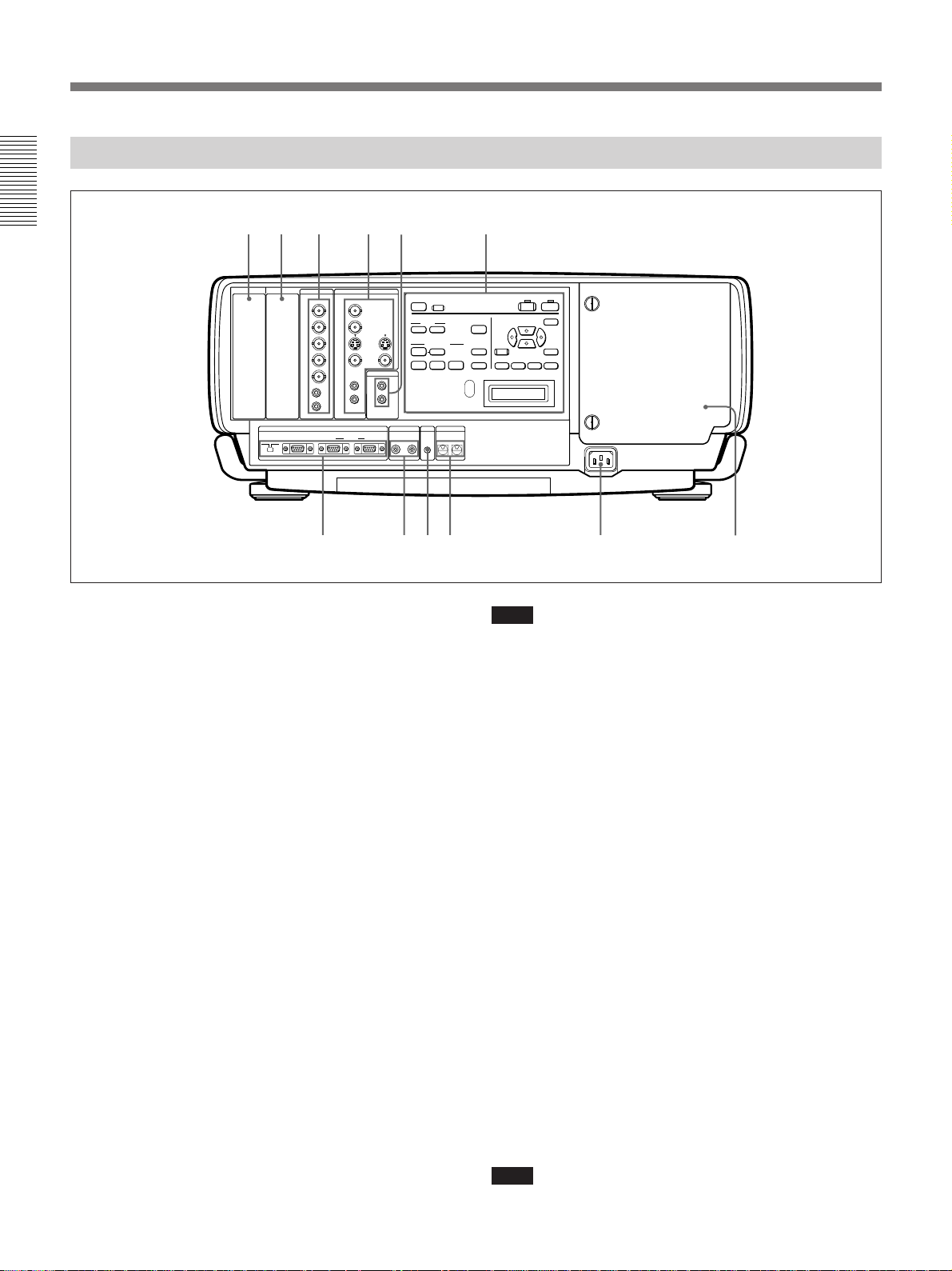
Location and Function of Controls
Rear
6 5 4 3 12
INPUT C INPUT B
INPUT A VIDEO
R/R-Y Y
G/Y
B/B-Y
SYNC
/HD
VD
AUDIO
IN
RS-
RS-
RS-232C/422A RS-485IN OUT IN OUT
232C
422A
IN
C
8
VIDEO8VIDEO
VIDEO
LRL
(MONO)
AUDIO
L
(MONO)
IN
R
REMOTE CONTROL S TRIG
VIDEO
AUDIO OUT
R
OUT
PLUG IN POWER
LIGHT
+
MUTING
PCI AUDIO
INPUT SELECT
VIDEO
SELECT
INPUT A INPUT B INPUT C
POWER SAVING
COVER FAIL
FAN FAIL
HIGHT TEMP
789!º !¡ !™
1 Control panel
For details, see pages 10 (GB) and 11 (GB).
2 AUDIO OUT L/R jacks (phono type)
Connect to external active speakers.
The volume of the speakers can be controlled by the
VOLUME keys on the Remote Commander or the
control panel.
3 VIDEO connectors
Connect to external video equipment, such as a VCR.
Y IN/C IN (BNC type): Connect to the Y and C
video outputs of the video equipment.
S VIDEO IN (mini DIN 4-pin): Connects to the Y/C
video output of the video equipment.
S VIDEO OUT (mini DIN 4-pin): Used as loop-
through output via the Y/C IN connectors or the S
VIDEO IN connector.
VIDEO IN (BNC type): Connects to the composite
video output connector of the video equipment.
VIDEO OUT (BNC type): Used as loop-through
output of the VIDEO IN connector.
AUDIO IN L (MONO)/R jacks (phono type):
Connect to the audio output jacks of equipment,
such as a VCR. For stereo equipment, use both the
L and R jacks; for monaural equipment, use the L
(MONO) jack only.
12 (GB)
VIDEO/
S VIDEO
LAMP FAIL
12
34
DEVICE INDEX
0 0
MENU
ENTER
FOCUSSHIFTZOOM
VOLUME
APA
+
RESET
PATTERN
–
Note
If you have video equipment connected to both the Y/
C IN and S VIDEO IN connectors, the signal from the
Y/C IN connectors are selected prior to the S VIDEO
IN connector. When projecting video connected to the
S VIDEO IN connector, be sure not to connect any
cable to the Y/C IN connectors.
Note on the VPL-X2000E model
The optional IFB-X2000E interface board is required
for using the VIDEO connectors.
4 INPUT A connectors
RGB input connectors (R/R-Y/P
R, G/Y, B/B-Y/PB,
SYNC/HD, VD) (BNC type): Connect to the
video outputs of equipment such as a computer or
a video camera.
According to the connected equipment, the RGB,
component (R-Y, Y, B-Y) or HDTV (P
R, Y, PB)
signal is selected.
AUDIO IN L (MONO)/R jacks (phono type):
Connect to the audio output jacks of equipment
such as a computer or a video camera. For stereo
equipment, use both the L and R jacks; for
monaural equipment, use the L (MONO) jack
only.
Note
The INPUT A connectors do not function when the
PC-3000 signal interface switcher is connected.
Page 13
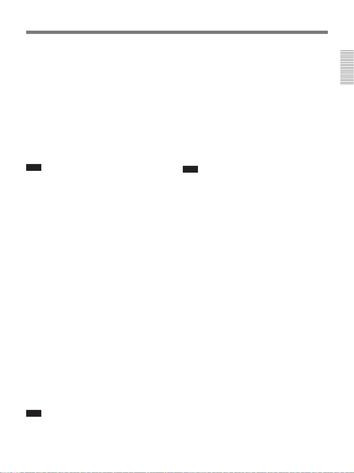
5 Signal interface board attachment part
(INPUT B)
Optional signal interface board can be attached
according to your requirements. If you install the IFB12A interface board to this section and select the
output mode, you can output the signal input through
the INPUT A connectors.
For details on installing the interface boards, consult with
qualified Sony personnel.
6 Signal interface board attachment part
(INPUT C)
Optional signal interface board can be attached
according to your requirements.
9 TRIG (trigger output) jack (monaural minijack)
The signal is transmitted from this jack to the
connected equipment whether the projector is on or
off. (This is not a power source for external
equipment.) Approximately 12 V DC signal is output
when the projector power is on. The signal is 0 volt
level output when the projector power is off.
!º DEVICE INDEX switch
Set the device index number of the projector when
using multiple projectors. You can set the numbers
between “01” and “99”. It is set to “01” at the factory.
You can also set the group index number in the menu
for system setup.
Note
You cannot select the output mode when attaching the
IFB-12A interface board.
7 REMOTE connectors
Used to expand system capability.
RS-232C/RS-422A select switch: Selects according
to the interface connected to the RS-232C/RS422A connector.
RS-232C/RS-422A connector (D-sub 9-pin,
female): Connect to a computer to operate the
projector from the computer.
PJ COM IN/OUT connectors (D-sub 9-pin,
female): The connectors conform to the RS-485
standards and are used to expand system
capability for Sony projectors.
For details on connections, see the PJ COM protocol
manual for Sony projectors.
8 CONTROL S IN/OUT jacks (stereo minijack)
Connect to the control S jacks of other Sony
equipment.
CONTROL S IN/PLUG IN POWER (DC 5 V
output) jack: Connects to the CONTROL S OUT
jack of the supplied Remote Commander when
using as a wired Remote Commander. In this case,
you do not need to install the batteries in the
Remote Commander, since the power is supplied
from this jack.
CONTROL S OUT jack: Outputs the control S
signal.
Note
Do not set the device index number to “00”. If you do,
the projector will be operated only with the keys on the
control panel.
!¡ AC IN socket
Connect the supplied AC Power cord.
!™ Lamp cover
Note
When connecting the remote commander cable to the
CONTROL S IN jack, the remote control detectors
will not function.
13 (GB)
Page 14
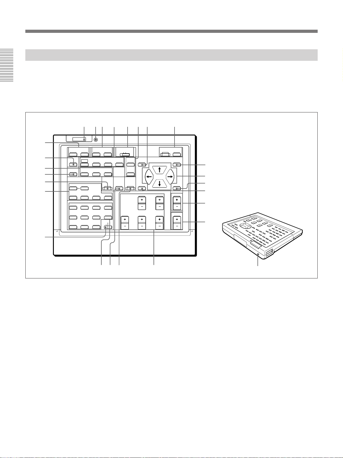
Location and Function of Controls
Remote Commander
The Remote Commander can be used as a wireless or wired Remote
Commander. The keys on the Remote Commander with the same names
function the same as those on the control panel of the projector.
For details on control panel keys on the projector, see pages 10 (GB) and 11
(GB).
ON
CENT
2
3
R
MEMORY
B
9
!º
!¡
LIGHT
MUTING
PIC ONAUDIO OFF
NORMAL
APA
LCD LENS CONTROL
ZOOM
PATTERN
STATUS
RGB
DOT PHASE
SHIFT
56784
COMMAND
OFF
SIZE
SHIFT
FOCUS
!™
!£
!¢
INPUT SELECT
VIDEO
SELECT
VIDEO/S VIDEO
ADBC
SWITCHER/VIDEO MEMORY/INDEX
1423
5867
SW NO/
9
10/0(ALL)
OFF/GROUP
SWITCHER INDEX
SYS SET
VIDEO MEMORY
BLKG
SHARP
RESET
FUNCTION
PICTURE CONTROL
BRIGHT
HUE
!∞
!§
!¶
!•
!ª
1 ON/STANDBY keys
2 MEMORY key
The key does not function with this projector.
3 CENT R/B keys
The keys do not function with this projector.
4 COMMAND ON/OFF key
No keys except for the LIGHT button on the Remote
Commander function when this switch is set to OFF.
This saves battery power.
5 RGB keys
Adjust the picture.
APA: The key functions the same as the APA key on
the control panel.
CONTR
COLOR
1
ONSTANDBY
MENU
@∞
@¢
ENTER
POSITION
@£
@™
@¡
VOL
@º
@§
DOT PHASE: Press to adjust the phase of the LCD
panels and the input signals (except for 15k RGB/
video/HDTV signals). After pressing this key,
adjust the position of the picture using the four
arrow keys so that the clearest picture is obtained.
SIZE: Enters the size adjustment mode for the input
signal. Next adjust the horizontal size of the
picture using the arrow keys.
B: to reduce horizontal size
b: to expand horizontal size
SHIFT: Enters the shift adjustment mode for the
input signal. Next adjust the position of the picture
using the four arrow keys. The picture shifts in the
direction of the arrow on the pressed key.
14 (GB)
Page 15
6 STATUS ON/OFF keys
Press OFF to eliminate the on-screen display.
Press ON to restore the on-screen display.
Note
The menus and warning messages appear even if the
OFF key is pressed.
7 Transmission indicator
The light goes on each time a key is pressed. If the
indicator does not light, replace the batteries.
8 LIGHT button
Illuminates the key indicators when the COMMAND
switch is set to ON. If the switch is set to OFF, only
the COMMAND switch is illuminated.
If you do not press any key on the Commander for
more than 30 seconds, the key indicators turn off
automatically. The indicators also turn off if you press
the LIGHT button again.
9 MUTING keys
!º NORMAL key
The key does not function with this projector.
!¡ LCD LENS CONTROL keys
Press one of the ZOOM, SHIFT and FOCUS keys and
then the arrow keys (V or v).
!™ PATTERN key
!£ SYS SET (system set) key
When the PC-3000 signal interface switcher is used in
the system or the system connections are changed,
press this key.
Note
After connecting the PC-3000 switcher and pressing
the SYS SET key, the input channel is set to SW1-1
when connecting a single switcher, or to SW1-2 when
connecting two or more switchers.
!¢ INPUT SELECT keys
The D key does not function with this projector.
!∞ SWITCHER/VIDEO MEMORY/INDEX select
switch
Selects the function of the SWITCHER/VIDEO
MEMORY/INDEX keys.
SWITCHER: selects the input from the PC-3000
switcher.
VIDEO MEMORY: The position does not function
with this projector.
INDEX: selects a projector by its index number
when multiple projectors are used.
!§ SWITCHER/VIDEO MEMORY/INDEX keys
When the SWITCHER/VIDEO MEMORY/
INDEX select switch is set to SWITCHER
When the PC-3000 switcher is connected to the
projector, press a number key (1 to 8) to select the
input from the switcher. Number key 9 does not
function.
To select an input when multiple switchers are
connected, press the SW NO/OFF/GROUP key. Next
press the switcher number (1 to 8) and the input
number (1 to 8) in sequence. Be sure to press the keys
one after another within 2 seconds.
e.g. To select input 4 of switcher 2, press the keys as
follows:
SW NO n 2 n 4.
When the SWITCHER/VIDEO MEMORY/
INDEX select switch is set to INDEX
Used to specify the device or group index number.
!¶ BLKG (blanking) adjustment key
Enters the blanking adjustment mode.
Next, press V/v key to select the position to be
adjusted on the screen, and then adjust the position
using the B/b keys.
!• RESET key
!ª PICTURE CONTROL +/– keys
Adjust the picture conditions: CONTR (contrast),
BRIGHT (brightness), COLOR, HUE and SHARP
(sharpness).
@º VOL (volume) +/– keys
@¡ POSITION +/– keys
These keys do not function with this projector.
(Continued)
15 (GB)
Page 16

Location and Function of Controls
@™ FUNCTION key
The key does not function with this projector.
@£ ENTER key
@¢ Arrow keys
@∞ MENU key
@§ CONTROL S OUT jack
Connect the supplied remote control cable to this jack
and to the CONTROL S IN jack of the projector for
wired remote control operation.
When the Commander is connected to the CONTROL
S IN/PLUG IN POWER jack of the projector via the
remote control cable (stereo), the power for the
Remote Commander is supplied from the projector.
16 (GB)
Page 17
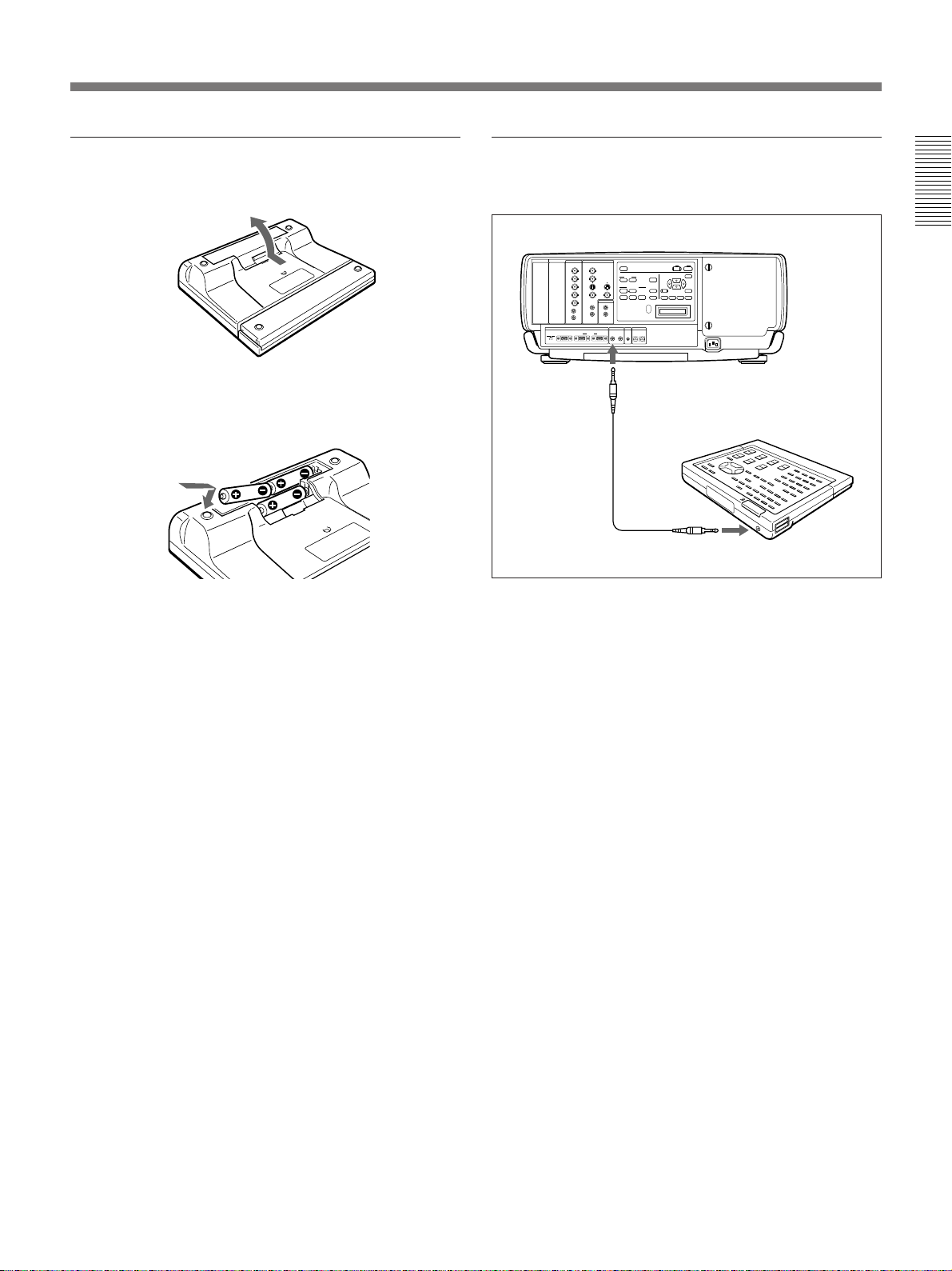
Battery installation
1 Push to open the lid.
2 Install three R6 (size AA) batteries (supplied) with
the polarities correctly aligned.
Be sure to install the battery
from the ’ side.
To connect the Remote Commander to the
projector
Rear
INPUT C INPUT B
INPUT A VIDEO
+
AUDIO OUT
REMOTE CONTROL S TRIG
to CONTROL
S IN
Remote
commander
cable (supplied)
–
DEVICE INDEX
0 0
Remote Commander
to CONTROL S OUT
3 Replace the lid.
Notes on batteries
•Make sure that the battery orientation is correct when
inserting batteries.
•Do not mix old battery with new one, or different
types of batteries.
•If you will not use the Remote Commander for a long
time, remove the batteries to avoid damage from
battery leakage. If batteries have leaked, remove
them, wipe the battery compartment dry and replace
the batteries with new ones.
Notes on wireless Remote Commander
operation
•Be sure that there is nothing to obstruct the infrared
beam between the Remote Commander and the
projector.
•The operation range is limited. The shorter the
distance between the Remote Commander and the
projector, the wider the angle within which the
commander can control the projector.
•The remote control detectors on the projector do not
operate when connecting the remote commander
cable to the CONTROL S IN jack. If you wish to use
the Remote Commander as a wireless Remote
Commander, be sure to remove the remote
commander cable from both the Remote Commander
and the projector.
Note on wired Remote Commander operation
using the supplied remote commander cable
(stereo)
You do not need to install the batteries since the power
is supplied from the CONTROL S IN jack on the
projector. In this case, the batteries are not consumed.
17 (GB)
Page 18
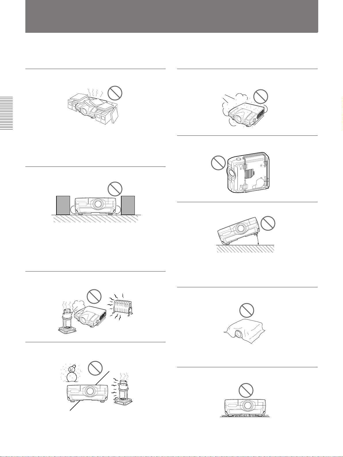
Precautions on Installation
Do not install the projector in the following situations. These installations
may cause malfunction or damage to the projector.
Do not install the projector in an illventilated place
The projector is equipped with ventilation holes for intake
on the bottom and front and ventilation holes for exhaust on
the left and right sides to prevent internal heat build-up. Do
not block these ventilation holes and allow adequate air
circulation at an installation location.
Do not place any object beside the
projector
If you put something beside the ventilation holes on the
sides, the exhaust may be inhaled into the projector through
the ventilation holes (intake) at the bottom, causing the
internal temperature to rise and thereby activating the
protection circuit. Install the projector so that the exhaust is
not blocked.
Do not install the projector in a location
where temperature or humidity is very high
Avoid installing the projector in a location
subject to excessive dust
Do not use the projector while laying it on
its side
Do not tilt the projector when in use
20°
Avoid tilting the projector more than 20 degrees or installing
it other than on the floor and ceiling. Such installations may
cause malfunctions such as color irregularity or shortening
of lamp life.
Do not cover the ventilation holes
(exhaust)
Avoid installing the projector in a location
where temperature may rise or fall rapidly
Be careful of air-conditioning and heating in a room where
the projector is installed, as sudden changes in temperature
may lead to moisture condensation and cause damage to the
projector.
18 (GB)
Do not cover the front ventilation holes; otherwise, internal
heat may build up.
Do not install the projector on a deep-pile
carpet
If you install the projector on a deep-pile carpet, the
ventilation holes (intake) at the bottom may be blocked,
causing an internal heat build-up.
Page 19
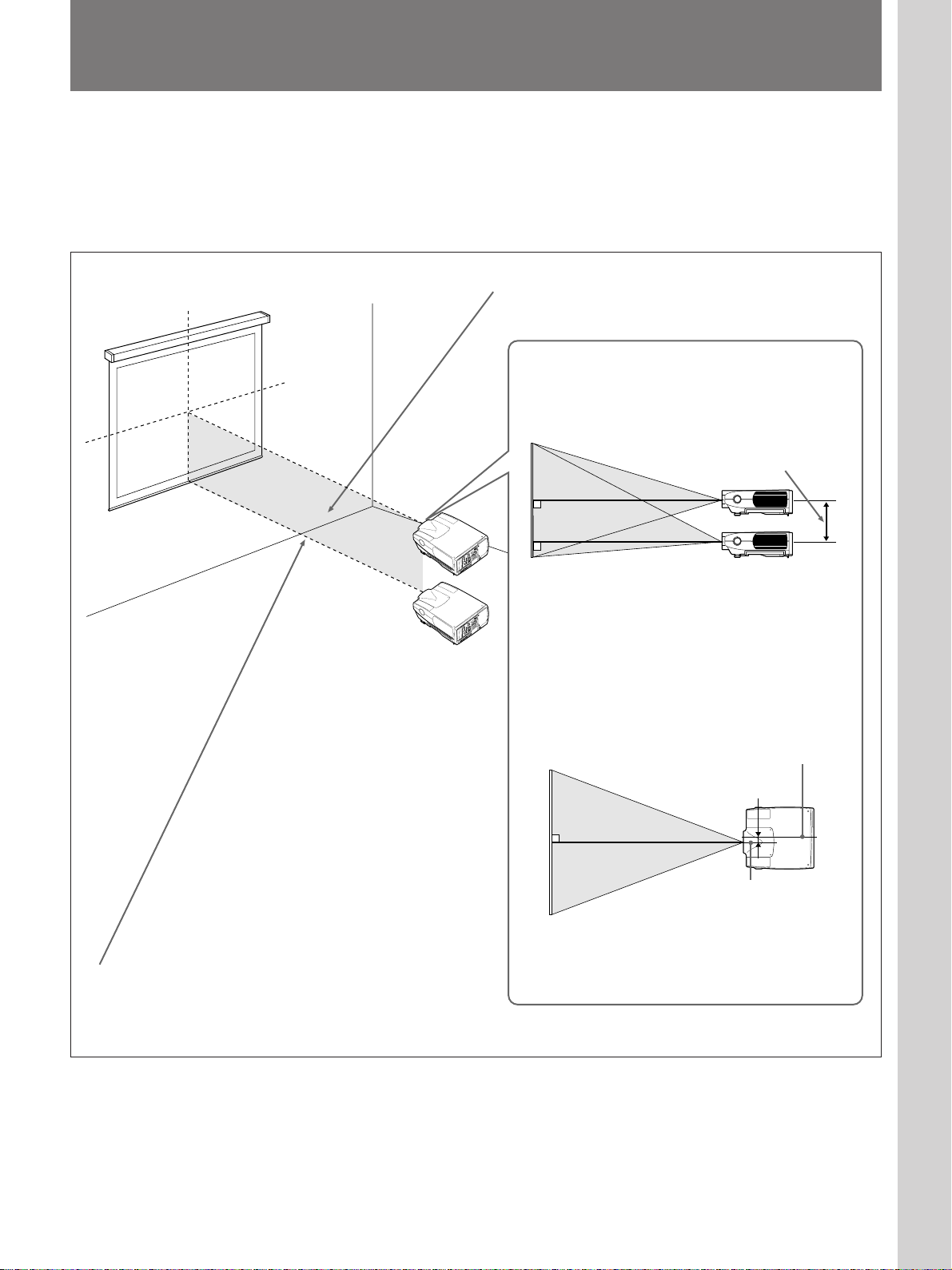
Installing the Projector on the Floor
This section describes the installation arrangements for installing the
projector on the floor. For details on installation examples, see pages 34
(GB) to 37 (GB).
For ceiling installation, consult with qualified Sony personnel (see page 38
(GB)).
Setting up and projecting
Horizontal center of the screen
Vertical center
of the screen
Installation
area
Projection
distance
Install the projector so that the tip of the lens is within this area.
Adjust the vertical and horizontal positioning of the
projector.
Vertical positioning (side view)
Screen
Adjustable range
U
N
E
M
R
E
T
N
E
S
U
C
A
O
P
F
A
T
F
I
H
T
T
S
H
E
G
S
I
E
L
R
M
O
O
Z
G
O
N
O
I
I
T
N
D
R
+
U
DE
U
E
T
M
A
T
VI
A
E
P
M
U
L
I
T
O
C
C
V
/
P
E
O
L
E
O
E
IN
D
–
E
S
I
D
V
T
I
U
V
P
S
T
N
I
C
E
A
L
C
E
T
T
S
T
U
U
P
N
OU
I
NP
I
O
Y
E
D
I
B
V
T
U
P
N
I
L
B
I
T
A
A
F
U
T
P
P
U
M
C
P
A
IN
8
N
L
I
Y
O
E
R
/
D
I
2
R
V
G
N
I
V
A
S
1
C
R
T
E
U
L
W
I
8
O
4
O
A
O
E
P
F
INP
E
Y
D
/
I
R
D
T
I
E
V
G
V
3
U
V
O
O
L
I
C
A
O
F
I
N
D
A
P
F
O
M
AU
E
E
T
Y
D
-
I
T
B
V
H
/
G
B
I
X
H
E
L
D
N
I
E
C
I
V
C
E
N
D
Y
S
D
H
/
R
IG
L
)
R
O
0
T
N
O
M
O
(
I
S
D
U
L
0
A
O
N
I
D
R
V
R
T
)
O
N
N
T
O
O
U
C
M
(
O
L
N
I
O
I
D
U
A
N
I
R
E
T
R
W
U
O
P
O
N
I
G
U
L
P
5
8
4
-
E
S
R
OT
M
E
N
R
I
A
2
2
4
/
C
2
3
2
S
R
S
R
A
2
2
S
4
R
C
2
3
2
You can adjust the angle of projection by performing
the shift adjustment (page 23 (GB)).
U
N
E
M
R
E
T
N
E
S
U
C
A
O
P
F
A
T
F
I
H
T
T
S
H
E
G
S
I
E
L
R
M
O
O
Z
G
N
O
I
I
EO
T
N
D
R
+
U
U
E
ID
M
T
A
T
V
A
E
P
M
U
L
I
T
O
C
C
V
/
P
E
O
L
E
O
E
IN
D
–
E
S
I
D
V
T
I
U
V
P
S
T
N
I
C
E
A
L
C
E
T
T
S
T
U
U
P
N
OU
I
NP
I
O
Y
E
D
I
B
V
T
U
P
N
I
L
B
I
T
A
A
F
T
P
PU
U
M
C
P
IN
A
8
N
L
I
Y
O
E
R
/
D
I
2
R
V
G
N
I
V
A
S
1
C
R
T
E
L
W
I
8
O
4
O
A
O
E
P
F
INPU
E
Y
D
/
I
R
D
T
E
I
V
G
V
3
V
O
OU
L
I
C
A
O
F
I
N
D
A
U
P
F
O
M
A
E
E
T
Y
D
-
I
T
B
V
H
/
G
B
I
X
H
E
L
D
N
I
E
C
I
V
C
E
N
D
Y
S
D
H
G
/
R
I
L
)
R
O
0
T
N
O
M
O
(
I
D
S
U
L
0
A
O
N
I
D
V
R
TR
)
O
N
T
ON
O
U
C
M
(
O
L
N
I
O
I
D
U
A
N
I
R
E
T
R
W
U
O
P
O
N
I
G
U
L
P
5
8
4
-
E
S
R
OT
M
E
N
R
I
A
2
2
4
/
C
2
3
2
S
R
S
R
A
2
2
S
4
R
C
2
3
2
• Install the projector so that the center of the lens is
between just above the bottom edge of the screen
and the center of the screen.
• When using the VPLL-2009, make sure that the
center of the lens is aligned with the vertical center
of the screen.
Horizontal positioning (top view)
Screen
Center of the projector
The distance between the lens and the screen varies
depending on the size of the screen and the attached
lens. Use the tables on pages 35 (GB) to 37 (GB).
38 mm (1 1/2 inches)
Center of the lens
Adjust the horizontal positioning of the projector so
that the center of the lens is aligned with the
horizontal center of the screen.
19 (GB)
Page 20
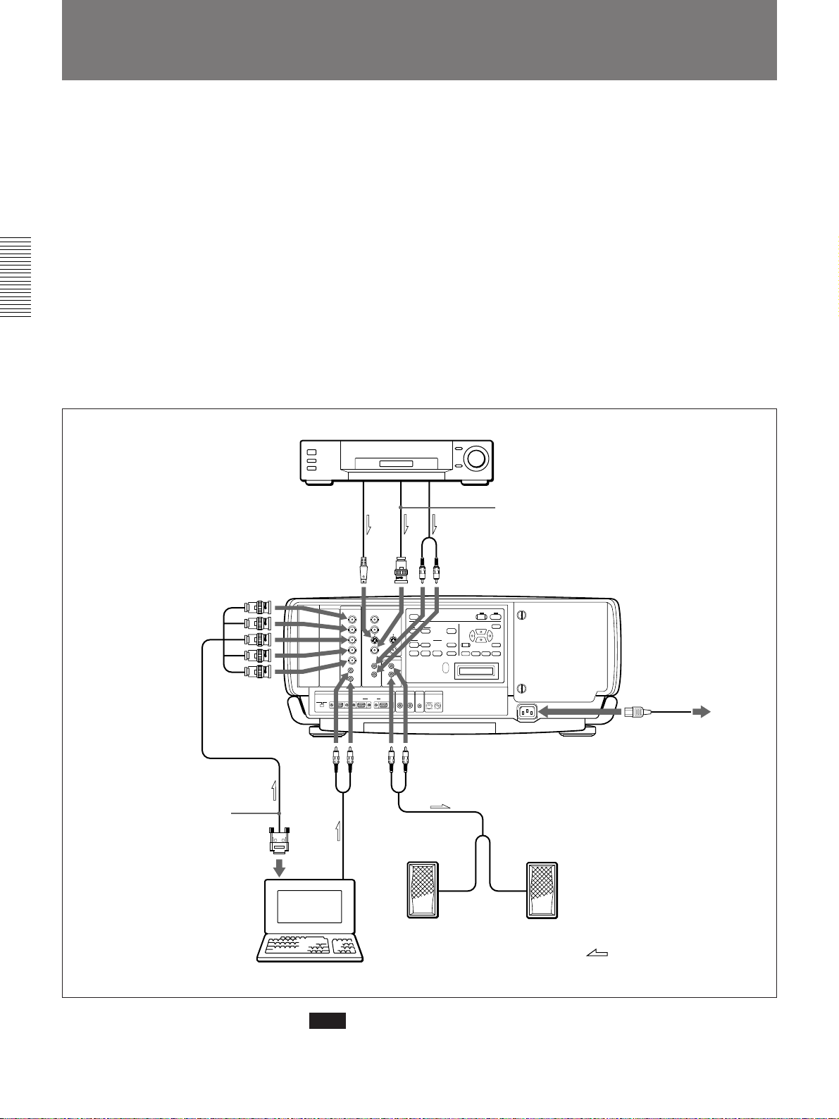
Connecting with a Computer or a VCR
This section describes how to connect the projector with a computer, VCR,
and external active speakers. For details on how to connect other
equipment, see pages 42 (GB) to 44 (GB).
Also refer to the instruction manuals of the equipment to be connected.
When making connections, be sure to:
•turn off all equipment before making any connections.
•use the proper cables for each connection.
•insert the plugs of the cables properly; plugs that are not fully inserted
often generate noise. When pulling out a cable, be sure to pull it out by
the plug, not the cable itself.
Note on the VPL-X2000E model
The optional IFB-X2000E interface board is required for using the VIDEO
connectors.
VCR
SMF-400 Monitor cable
(5BNC˜HD D-sub 15-pin)
(not supplied)
Use the optional ADP-20
Signal adapter when
connecting with a Macintosh
computer.
to S VIDEO OUT
S video cable
(not supplied)
Rear
INPUT C INPUT B
INPUT A VIDEO
REMOTE CONTROL S TRIG
Audio cable
(not supplied)
to
VIDEO
OUT
AUDIO OUT
to AUDIO OUT
Audio cable
(not supplied)
+
–
DEVICE INDEX
1
0
Audio cable
(not supplied)
Video cable (not supplied)
to AC IN
to a wall outlet
AC power cord
(supplied)
20 (GB)
Active speakers
Computer
Note
Set INPUT-A in the SIGNAL SELECT menu to RGB.
For details, see page 32 (GB).
:
Signal flow
Page 21
Projecting
STANDBY indicator
INPUT C INPUT B
INPUT A VIDEO
AUDIO OUT
REMOTE CONTROL S TRIG
DEVICE INDEX
Rear remote control detector
LIGHT
RESET
SYS SET+
2
+
–
0 0
MUTING
PIC AUDIO
INPUT SELECT
VIDEO
SELECT
INPUT A INPUT B INPUT C
LAMP FAIL
POWER SAVING
COVER FAIL
12
FAN FAIL
34
HIGHT TEMP
APA
VOLUME
+
PATTERN
–
ON indicator
ON
STANDBY
MENU
ENTERRESET
ZOOM SHIFT FOCUS
1
4,5,6,7
7
4,6
5
3,8
7
5
3,8
2
LIGHT
MUTING
STATUS
PIC ONAUDIO OFF
RGB
NORMAL
DOT PHASE
APA
LCD LENS CONTROL
ZOOM
PATTERN
VIDEO
SWITCHER/VIDEO MEMORY /INDEX NO
SHIFT
INPUT SELECT
SELECT
VIDEO/S VIDEO
ADBC
1423
5867
SW NO/
9
10/0(ALL)
OFF/GBOUP
FOCUS
SYS SET
VIDEO MEMORY
SWITCHERINDEX
COMMAND
ON
OFF
CENT
R
SHIFT
BLKG
RESET
SHARP
MEMORY
B
PUNCTION
PICTURE CONTROL
BRIGHT
HUE
SIZE
CONTR
COLOR
ONSTANDBY
MENU
ENTER
POSITION
VOLUME
4,6
1
4,5,6,7
2
2
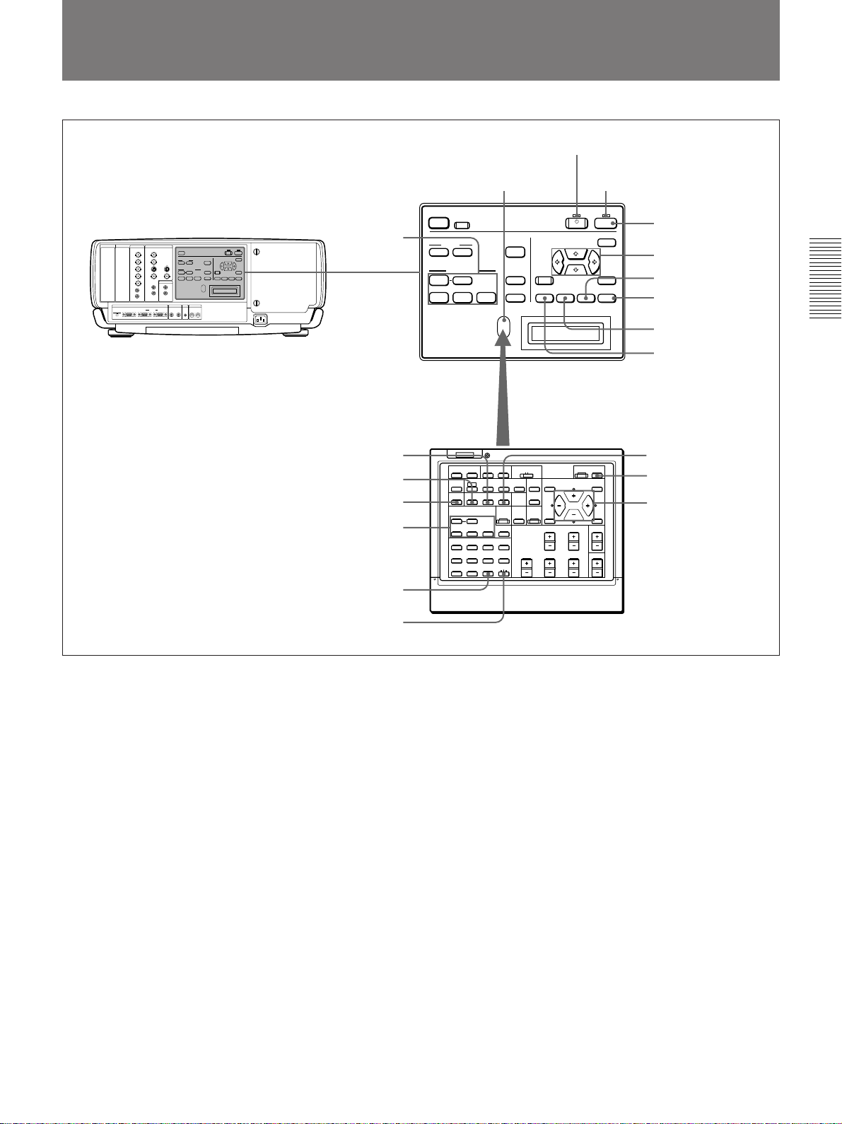
1 Press the ON key on the Remote Commander or the control panel.
The ON indicator lights in green.
2 Turn on the power of equipment connected to the projector. Press the
INPUT SELECT keys on the Remote Commander or the control panel
to select the input source.
VIDEO: Selects the video signal input from the VIDEO or S VIDEO
connectors and the audio signal input from the AUDIO IN L/R
jacks. To switch the VIDEO or S VIDEO connectors, use the
SELECT key.
SELECT: Each time you press this key, the input signal is switched
between VIDEO and S VIDEO.
INPUT A: Selects the audio and video signals input from the INPUT
A connectors.
INPUT B: Selects the signal input from the connectors on the optional
interface board which is installed in the INPUT B section.
INPUT C: Selects the signal input from the connectors on the optional
interface board which is installed in the INPUT C section.
(Continued)
21 (GB)
Page 22
Projecting
When you input the signal from equipment connected to the PC-3000
signal interface switcher (not supplied), set the SWITCHER/VIDEO
MEMORY/INDEX select switch on the Remote Commander to the
SWITCHER position and press the number keys to select the input.
When multiple switchers are connected, press the SW NO/OFF/
GROUP key, then press the number keys to select the input.
Note
Press the SYS SET key when you make the system connections using
the PC-3000 switcher.
Note on the VPL-X2000E model
The optional IFB-X2000E is required for selecting VIDEO.
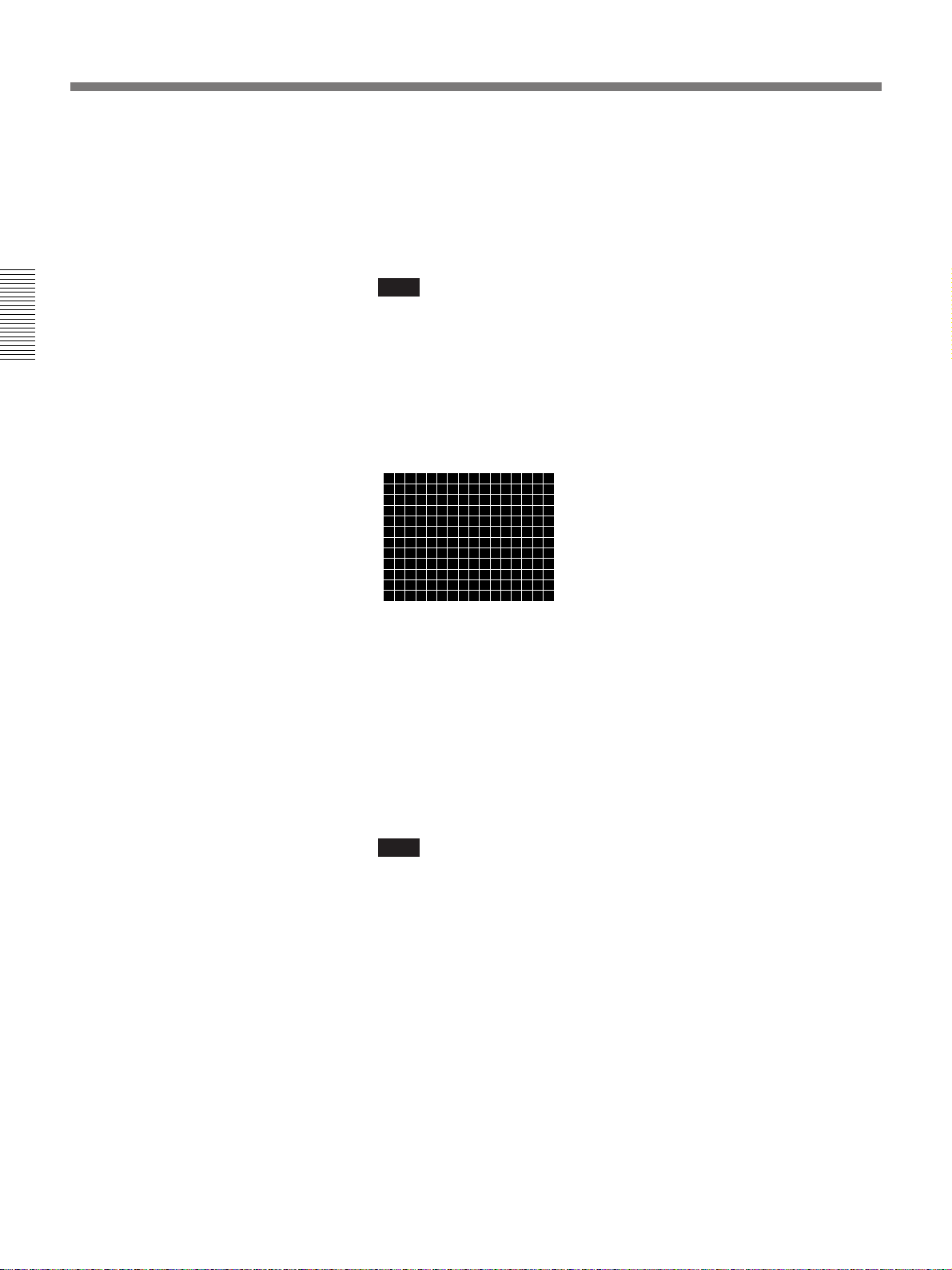
3 Press the PATTERN key on the Remote Commander or the control
panel to display the HATCH pattern.
4 Press the FOCUS key then the V or v key on the Remote Commander
or the control panel to adjust the focus.
“FOCUS” appears on the screen during adjustment.
5 Press the ZOOM key then the V or v key on the Remote Commander
or the control panel to adjust the picture size.
“ZOOM” appears on the screen during adjustment.
Note
If the optional VPLL-2075, VPLL-2014 or VPLL-2009 lens is
installed, you cannot adjust the zoom.
6 Press the FOCUS and arrow keys on the Remote Commander or the
control panel to adjust the focus again.
“FOCUS” appears on the screen during adjustment.
22 (GB)
Page 23
7 Press the SHIFT key then the arrow keys on the Remote Commander
or the control panel to adjust the vertical position of the picture.
“PICTURE SHIFT” appears on the screen during adjustment.
8 Press the PATTERN key again to clear the HATCH pattern.
To turn off the power
To
Adjust the volume
Cut off the sound
Cut off the picture
Note
Press
the VOLUME +/– keys.
the AUDIO MUTING key (also cuts off the signal output
from the AUDIO OUT jacks.)
To restore the sound, press the AUDIO MUTING key again
or press the VOLUME + key.
the PIC MUTING key.
To restore the picture, press the PIC MUTING key again.
Do not look into the lens when the projector lamp is on.
1 Press the STANDBY key on the Remote Commander or the control
panel.
The ON indicator flashes in green and the cooling fan keeps running
for about six minutes to reduce the internal heat. The ON indicator
flashes quickly for one minute. During this time, you will not be able
to turn the power back on. After about one minute, you can turn on the
power with the ON key.
When the fan stops running, the STANDBY indicator lights in red.
Note
To extend the lamp life, do not turn off the power for at least 10
minutes after turning on the power.
23 (GB)
Page 24
Using the Menu
The projector is equipped with an on-screen menu for
making various adjustments and settings.
Unadjustable items are not displayed in the menu.
To change the language used in the menu, see page
30 (GB).
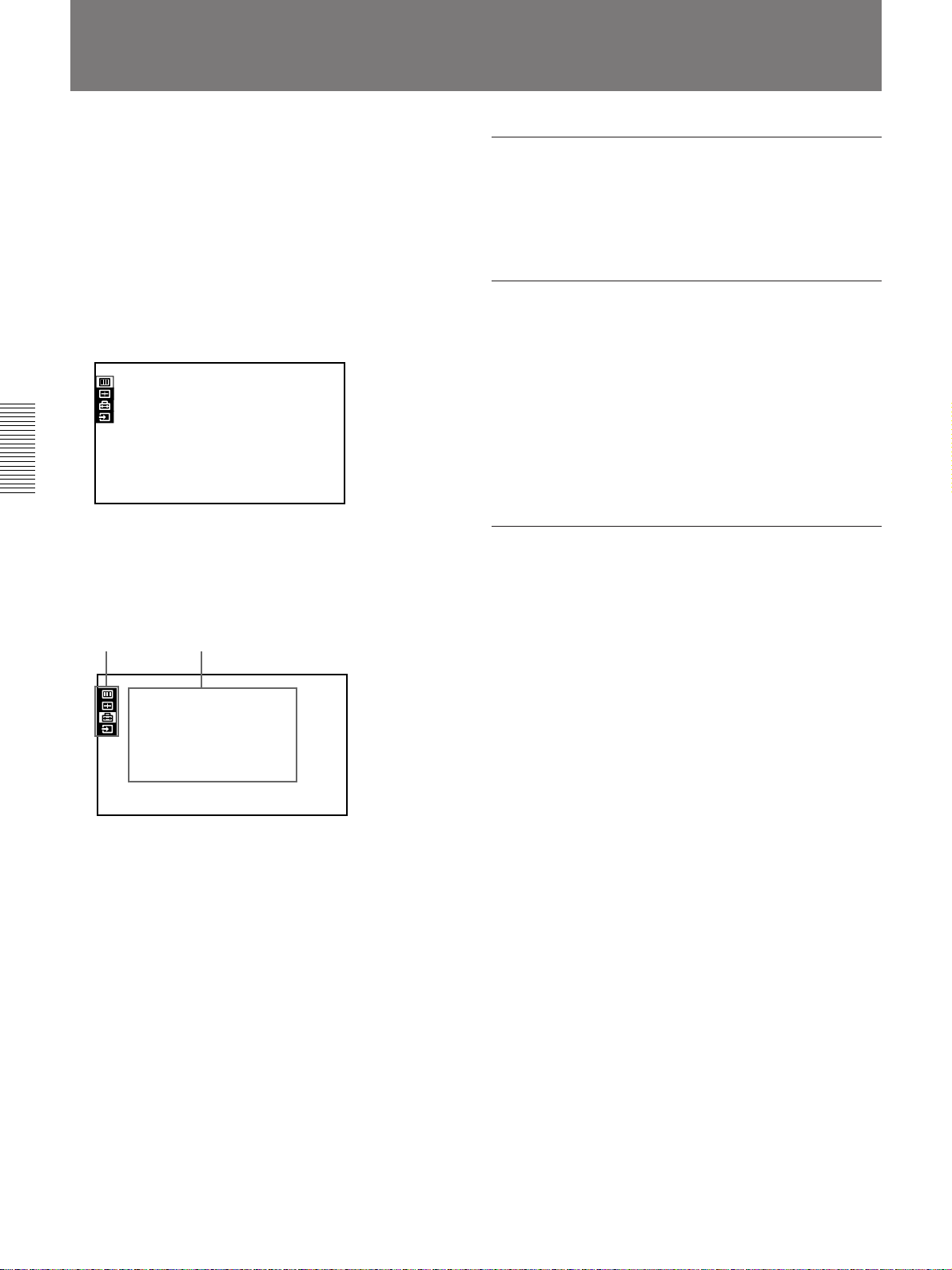
1 Press the MENU key.
The menu display appears.
The menu presently selected is highlighted in
yellow.
PICTURE CTRL
CONTRAST:
BRIGHT:
COLOR:
HUE:
SHARP:
D.PICTURE:
COLOR TEMP:
COLOR SYS: AUTO
DRC:
80
50
50
50
50
OFF
LOW
HIGH
VIDEO
2 Use the V or v key to select a menu, then press the
b or the ENTER key.
The setting items of the selected menu are
displayed.
Menus
Setting items
To erase the menu display
Press the MENU key. The menu display also
disappears automatically if no key is pressed for one
minute.
To reset settings that have been adjusted
Press the RESET key.
“Reset complete!” appears on the screen and the
settings appearing on the screen will be reset to their
factory preset values.
Items that can be reset are as follows:
CONTRAST, BRIGHT, COLOR, HUE, SHARP,
DOT PHASE, SIZE, SHIFT and BLANKING.
About the memory of the settings
The settings are automatically stored in the projector
memory.
SET SETTING
STATUS:
SPEAKER:
LANGUAGE:
INSTALLATION:
POWER SAVING
SIRCS RECEIVER
GROUP INDEX:
DEVICE INDEX:0101
ON
ON
ENGLISH
FLOOR-FRONT
OFF
:
FRONT&REAR
:
INPUT-A
3 Make setting or adjustment on an item.
For details on setting individual items, see the relevant
menu pages.
24 (GB)
Page 25
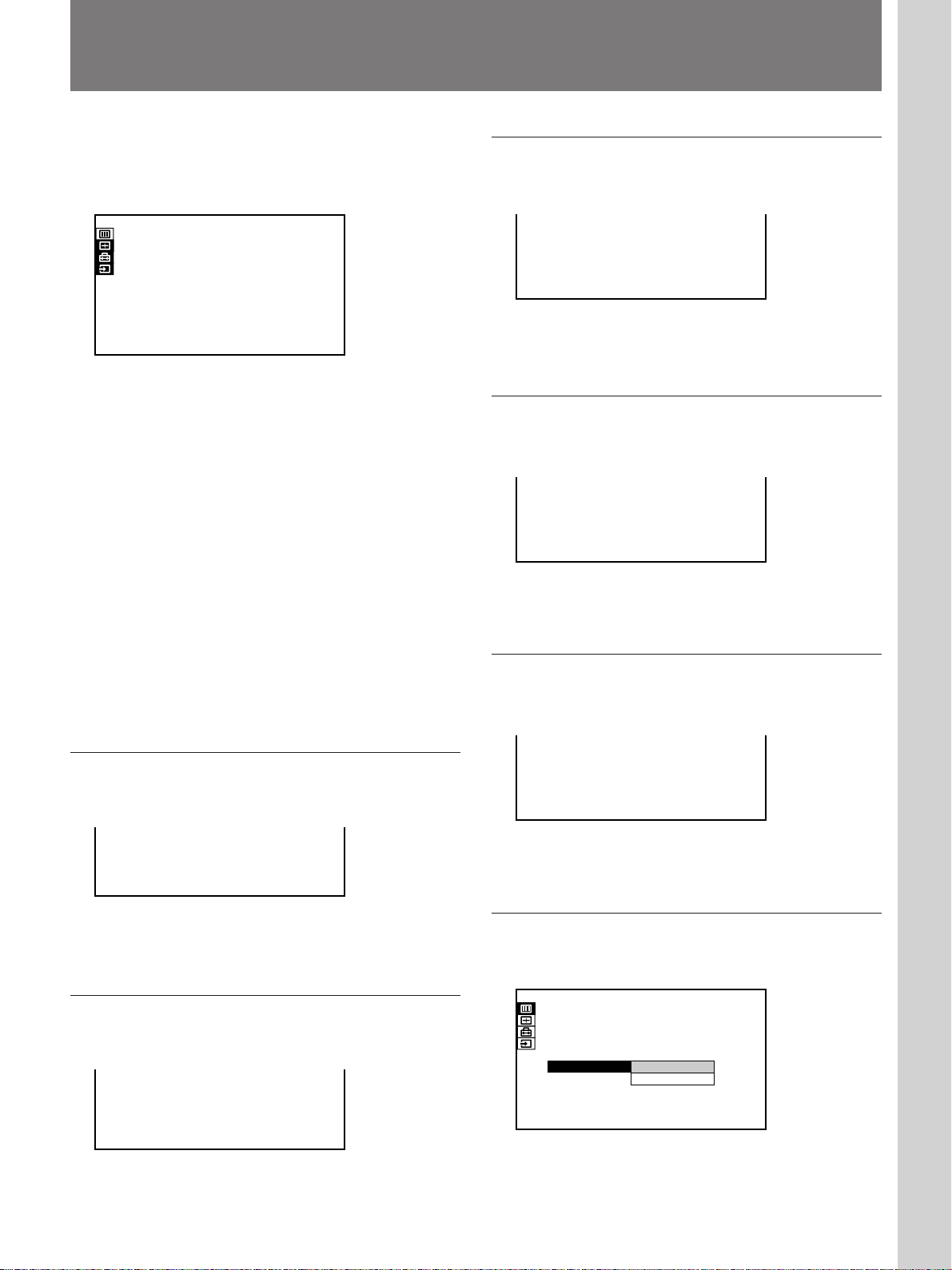
The PICTURE CTRL Menu
Adjustments and settings using the menu
The PICTURE CTRL menu is used for adjusting the
picture. Unadjustable items are not displayed in the
menu.
PICTURE CTRL
CONTRAST:
BRIGHT:
COLOR:
HUE:
SHARP:
D.PICTURE:
COLOR TEMP:
COLOR SYS: AUTO
DRC:
80
50
50
50
50
OFF
LOW
HIGH
VIDEO
Operation
1. Select an item
Use the V or v key to select the item, then press the b
or the ENTER key.
2. Adjust an item
•When changing the adjustment level:
To increase the number, press the V or b key.
To decrease the number, press the v or B key.
Press the ENTER key to restore the original screen.
COLOR
Adjusts color intensity.
COLOR: 50
The higher the setting, the greater the intensity.
The lower the setting, the lower the intensity.
HUE
Adjusts skin tones.
HUE: 50
At high settings, the picture becomes greenish.
At low settings, the picture becomes purplish.
•When changing the setting:
Press the V or v key to change the setting, then press
the B or the ENTER key.
The original screen is restored.
CONTRAST
Adjusts the picture contrast.
CONTRAST: 80
The higher the setting, the greater the contrast.
The lower the setting, the lower the contrast.
BRIGHT (Brightness)
Adjusts the picture brightness.
SHARP (Sharpness)
Adjusts the picture sharpness.
SHARP: 80
The higher the setting, the sharper the picture.
The lower the setting, the softer the picture.
D. (Dynamic) PICTURE
Emphasizes the black color.
PICTURE CTRL
CONTRAST:
BRIGHT:
COLOR:
HUE:
SHARP:
D.PICTURE:
COLOR TEMP:
COLOR SYS: AUTO
DRC:
80
50
50
50
50
OFF
OFF
ON
HIGH
HIGH
VIDEO
BRIGHT: 80
The higher the setting, the brighter the picture.
The lower the setting, the darker the picture.
ON: Emphasizes the black color to produce a bolder
“dynamic” picture.
OFF: Reproduces the dark portions of the picture
accurately, in accordance with the source signal.
25 (GB)
Page 26
The PICTURE CTRL Menu
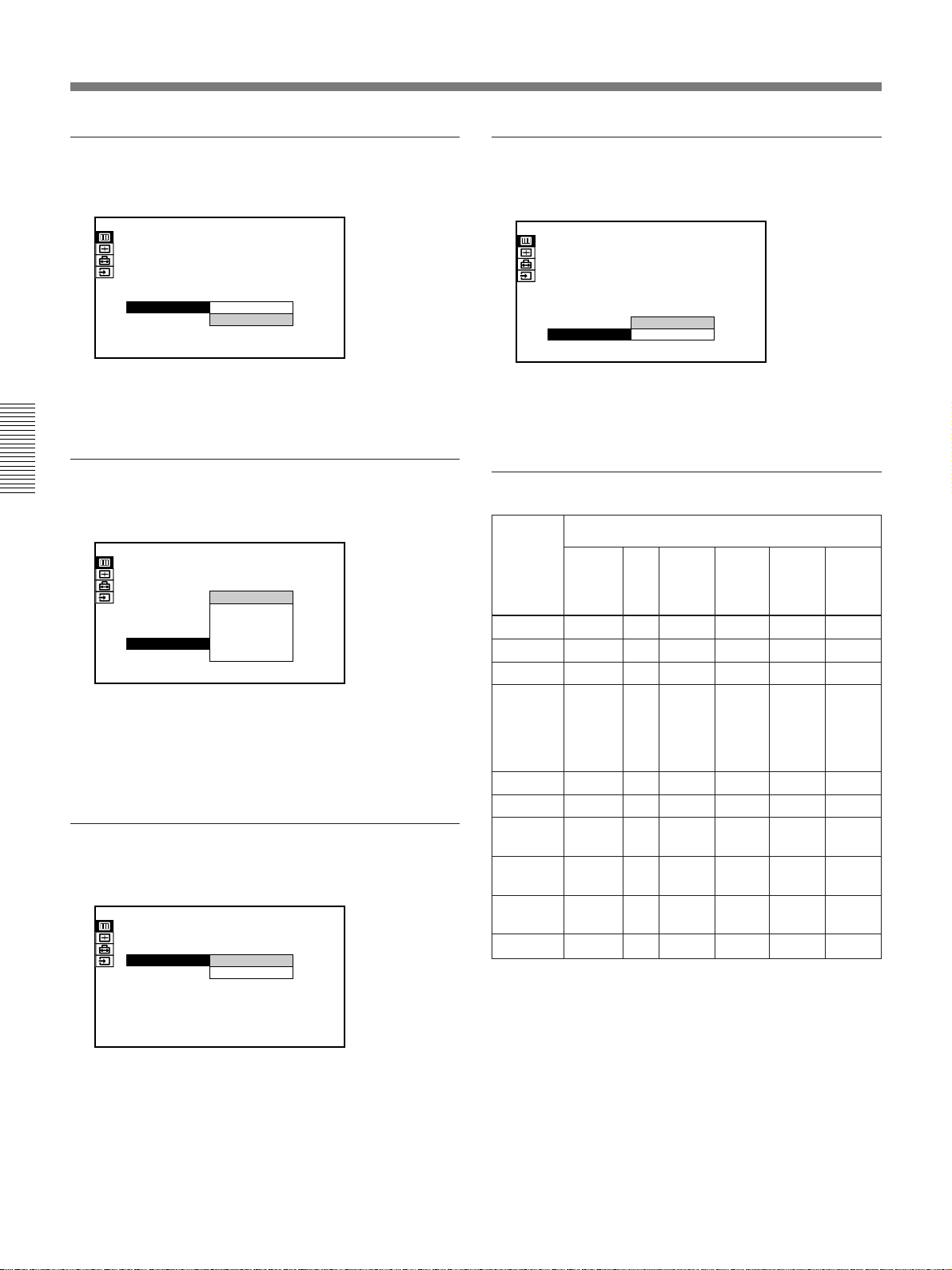
COLOR TEMP (temperature)
Adjusts the color temperature.
PICTURE CTRL
CONTRAST:
BRIGHT:
COLOR:
HUE:
SHARP:
D.PICTURE:
COLOR TEMP:
COLOR SYS: AUTO
DRC:
80
50
50
50
50
OFF
HIGH
HIGH
LOW
HIGH
VIDEO
HIGH: Makes the white color bluish.
LOW: Makes the white color reddish.
COLOR SYS (system)
Selects the color system of the input signal.
PICTURE CTRL
CONTRAST:
BRIGHT:
COLOR:
HUE:
SHARP:
D.PICTURE:
COLOR TEMP:
COLOR SYS:
DRC:
80
50
50
50
AUTO
NTSC3.58
50
PAL
OFF
SECAM
HIGH
AUTO
NTSC4.43
HIGH
PAL-M
VIDEO
Normally, set to AUTO.
If the picture is distorted or colorless, select the color
system (NTSC
3.58/PAL/SECAM/NTSC4.43/PAL-M)
according to the input signal.
GAMMA MODE
Select either position to obtain an optimum picture.
PICTURE CTRL
CONTRAST:
BRIGHT:
COLOR TEMP:
GAMMA MODE:GRAPHICS
80
50
HIGH
GRAPHICS
TEXT
INPUT-A
DRC (Digital Reality Creation)
Selects the level of DRC effects.
PICTURE CTRL
CONTRAST:
BRIGHT:
COLOR:
HUE:
SHARP:
D.PICTURE:
COLOR TEMP:
COLOR SYS: AUTO
DRC:
80
50
50
50
50
OFF
LOW
HIGH
LOW
HIGH
VIDEO
HIGH: Increases the DRC effects.
LOW: Decreases the DRC effects.
Input signals and adjustable/setting items
Input signal
Item
CONTRAST
BRIGHT
COLOR
HUE
Video
or
S video
Y
Y
Y
Y
15k
RGB
Y
Y
N
N
Compo-
nent
(NTSC
3.58/
1)
4.43
only)
SHARP
D. PICTURE
COLOR
Y
Y
Y
N
N
Y
TEMP
COLOR
Y
N
SYS
GAMMA
N
N
MODE
DRC
Y
Y
Y: Adjustable/can be set
N: Not adjustable/cannot be set
RGB
(preset)
Y
Y
Y
N
Y
Y
Y
N
N
Y
RGB
(preset)
(HDTV-
Y/P
Y
Y
N
N
N
N
Y
N
Y
N
B/PR)
Y
Y
Y
Y
Y
N
Y
N
N
N
RGB
(not
preset)
Y
Y
N
N
N
N
Y
N
Y
N
GRAPHICS: Improves the reproduction of half
tones. Photos can be reproduced in natural tones.
TEXT: Contrasts black and white. Suitable for
images with lots of text.
..........................................................................................................................................................................................................
1) NTSC4.43 is the color system used when playing back a video recorded in
NTSC color system on a NTSC4.43 system VCR.
26 (GB)
Page 27
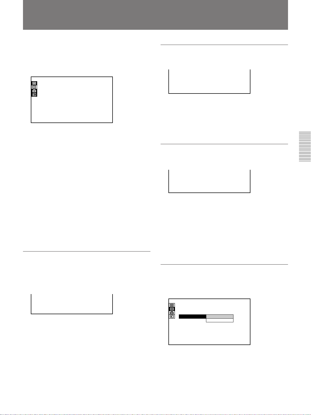
The INPUT SETTING Menu
The INPUT SETTING menu is used to change the
settings of the input signal. Unadjustable items, which
vary according to the input signal, are not displayed in
the menu.
INPUT SETTING
DOT PHASE:
SIZE
SHIFT
8
H:1344
H:123 V:123
INPUT-A
1024x768
NO . 2 3
n 20
Operation
1. Select an item
Use the V or v key to select the item, then press the b
or the ENTER key.
2. Adjust an item
•When changing the adjustment level:
To increase the number, press the V or b key.
To decrease the number, press the v or B key.
Press the ENTER key to restore the original screen.
•When changing the setting:
Press the V or v key to change the setting, then press
the B or the ENTER key.
The original screen is restored.
DOT PHASE
SIZE
Adjusts the horizontal size of the picture.
SIZE
H:1344
As the setting for H increases, the horizontal size of
the picture becomes larger, and as the setting
decreases, the size becomes smaller. Adjust the setting
according to the input signal.
Use the B or b key to adjust the horizontal size.
SHIFT
Adjusts the position of the picture.
H:123 V:123
SHIFT
H adjusts the horizontal position of the picture, and
V adjusts the vertical position. As the setting for H
increases, the picture moves to the right, and as the
setting decreases, it moves to the left.
As the setting for V increases, the picture moves up,
and as the setting decreases, it moves down.
Use the B or b key to adjust the horizontal position
and the V or v key for the vertical position.
Adjusts the phase of the LCD panel and the input
signal when H FILTER is set to OFF.
Adjust the value to obtain the clearest picture.
DOT PHASE: 8
SCAN CONV (converter)
Converts the signal to display the picture according to
the screen size.
INPUT SETTING
DOT PHASE:
SIZE
SHIFT
SCAN CONV: ON
8
H:1056
H:123 V:123
ON
OFF
INPUT-A
800x600
NO . 1 7
n
21
ON: Displays the picture according to the screen
size. The picture will lose some clarity.
OFF: Displays the picture while matching one pixel
of input picture element to that of the LCD. The
picture will be clear but the picture size will be
smaller.
27 (GB)
Page 28
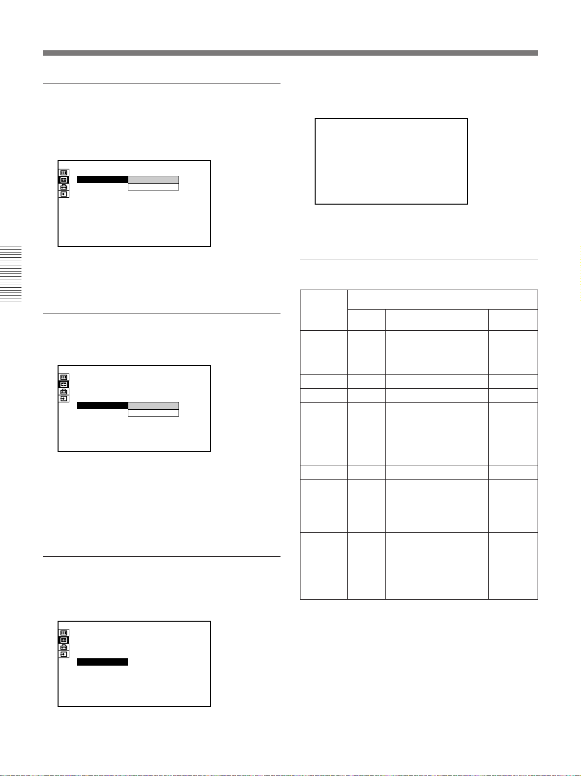
The INPUT SETTING Menu
ASPECT
Sets the aspect ratio of the picture.
When inputting 16:9 (squeezed) signal from
equipment such as a DVD player, set to 16:9.
INPUT SETTING
SHIFT
ASPECT: 4:3
BLANKING TOP
H:123 V:123
4:3
16:9
VIDEO
VIDEO/60
NO. 1
n
22
4:3: When the picture with ratio 4:3 is input
16:9: When the picture with ratio 16:9 (squeezed) is
input.
H FILTER
Corrects the vertical bands that appear on the picture.
INPUT SETTING
DOT PHASE:
SIZE
SHIFT
SCAN CONV:
H FILTER: OFF
8
H:1266
H:123 V:123
ON
OFF
ON
INPUT-A
1280x1024
NO . 3 7
n
23
The vertical bands may occur when an RGB signal
with horizontal resolution of more than 1024 × 768
pixels is input. In such cases, set to ON. The picture
will loose some clarity, but the vertical bands will be
reduced. Set to OFF to associate a dot of the input
signal with a pixel of the LCD.
BLANKING
Adjusts if excess signals are seen with the picture, or
the whole picture is not seen clearly.
INPUT SETTING
DOT PHASE:
SIZE
SHIFT
SCAN CONV:
BLANKING
8
H:1056
H:123 V:123
ON
INPUT-A
800×600
NO .
0
n
24
Select BLANKING, then press the ENTER key to
display the blanking adjustment screen.
BLANKING
TOP:
BOTTOM: 2 3 4
RIGHT:
LEFT:
126
57
34
Use the V or v key to select the part to be adjusted, and
the B or b key to adjust.
Input signals and adjustable/setting items
Item
Video or
S video
DOT PHASE
SIZE
SHIFT
SCAN CONV
ASPECT
H FILTER
BLANKING
N
N
Y
N
Y
N
Y
(TOP and
BOTTOM
BOTTOM
only)
Y: Adjustable/can be set
N: Not adjustable/cannot be set
15k
RGB
N
N
Y
N
Y
N
Y
(TOP
and
only)
Input signal
Compo-
nent
N
N
Y
N
Y
N
Y
(TOP and
BOTTOM
only)
RGB
(preset)
Y
(except
for
HDTV)
Y
Y
Y
(Only for
lower
resolution
than
SVGA)
N
Y
(Higher
resolution
than
XGA)
Y
(HDTV-
GBR,
HDTV-
B/PR
Y/P
only)
RGB
(not preset)
Y
Y
Y
Y
N
Y
(Higher
resolution
than XGA)
Y
28 (GB)
Page 29
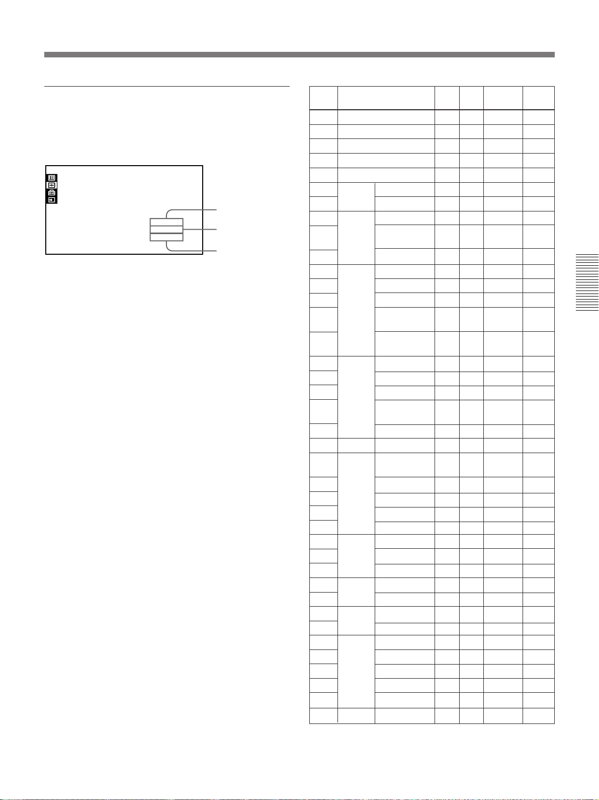
INPUT MEMORY No.
The upper number indicates the memory number of the
current input signal. The lower number indicates the
user memory number.
INPUT SETTING
DOT PHASE:
SIZE
SHIFT
8
H:1048
H:123 V:123
About the memory function
The adjustment data for 39 types of input signals are
preset at the factory (preset memory).
When a signal is input to the projector, the signal type
is automatimally detected and the data for the signal is
called from the memory to display an optimum picture.
The data can be adjusted in the INPUT SETTING
menu and the adjusted data will be saved as user
memory.
When you save more than 200 user memories, the
newest one always overwrites the oldest one.
The saved user memory number is displayed in the
INPUT SETTING menu as n NO. ππ.
When an RGB signal other than the preset signals is
input to the projector, the memory number is displayed
as 0 and the closest option is automatically selected
from the preset 39 types of signals.
INPUT-A
1024x768
NO. 1
n 23
Type of input signal
Memory number
User memory
number
Memory
Preset signal
No.
1
Video 60 Hz
2
Video 50 Hz
3
15k RGB (60 Hz)
15k RGB (50 Hz)
4
HDTV
5
640 × 350 VGA-1 (VGA350)
6
7
640 × 400 NEC PC98
8
9
10
640 × 480 VGA VESA60
11
12
13
14
15
16
800 × 600 SVGA VESA 56
17
18
19
20
21
832 × 624 Mac 16
22
1024 × 768 XGA VESA 43
23
24
25
26
27
1152 × 864 VESA 70
28
29
30
1152 × 900 SUN LO
31
32
1280 × 960 VESA 60
33
34
1280 × 1024
35
36
37
38
39
1600 × 1200
VESA* 85(VGA350)
VGA-2 (TEXT)
/VESA70
VESA 85 (VGA400)
Mac 13
VGA VESA 72
VGA VESA 75
(IBM M3)
VGA VESA 85
(IBM M4)
SVGA VESA 60
SVGA VESA 72
SVGA VESA 75
(IBM M5)
SVGA VESA 85
(8514)
XGA VESA 60
XGA VESA 70
XGA VESA 75
XGA VESA 85
VESA 75
VESA 85
SUN HI
VESA 75
SXGA VESA 43
SGI-5
SXGA VESA 60
SXGA VESA 75
SXGA VESA 85
UXGA VESA 60
fH
(kHz)
15.73
15.63
15.73
15.63
33.75
31.47
37.86
24.82
31.47
37.86
31.47
35.00
37.86
37.50
43.27
35.16
37.88
48.08
46.88
53.67
49.72
35.52
48.36
56.48
60.02
68.68
64.00
67.50
77.49
61.80
71.71
60.00
75.00
46.43
53.32
63.97
79.98
91.15
75.00
fV
(Hz)
59.94
50.00
59.94
50.00
60.00
70.09
85.08
54.42
70.09
85.08
59.94
66.67
72.81
75.00
85.01
56.25
60.32
72.19
75.00
85.06
74.55
86.96
60.00
69.96
75.03
85.00
70.02
75.00
85.06
65.96
76.05
60.00
75.00
86.87
50.06
60.01
75.03
85.02
60.00
Sync
S on G
S on G
S on Y/G
H-pos V-neg
H-pos V-neg
H-neg V-neg
H-neg V-pos
H-neg V-pos
H-neg V-neg
S on G
H-neg V-neg
H-neg V-neg
H-neg V-neg
H-pos V-pos
H-pos V-pos
H-pos V-pos
H-pos V-pos
H-pos V-pos
H-neg V-neg
H-pos V-pos
H-neg V-neg
H-neg V-neg
H-pos V-pos
H-pos V-pos
H-pos V-pos
H-pos V-pos
H-pos V-pos
H-neg V-neg
C-neg
H-pos V-pos
H-pos V-pos
H-pos V-pos
S on G
H-pos V-pos
H-pos V-pos
H-pos V-pos
H-pos V-pos
Horizontal
size
—
—
—
—
—
—
1235
800
832
848
800
832
800
—
832
840
832
1024
1056
1040
1056
1048
1152
1264
1344
1328
1312
1376
1308
1422
1394
1283
1256
1440
1382
1272
1260
1272
1266
1296
1352
* VESA is a registered trademark of Video Electronics
Standard Association.
29 (GB)
Page 30
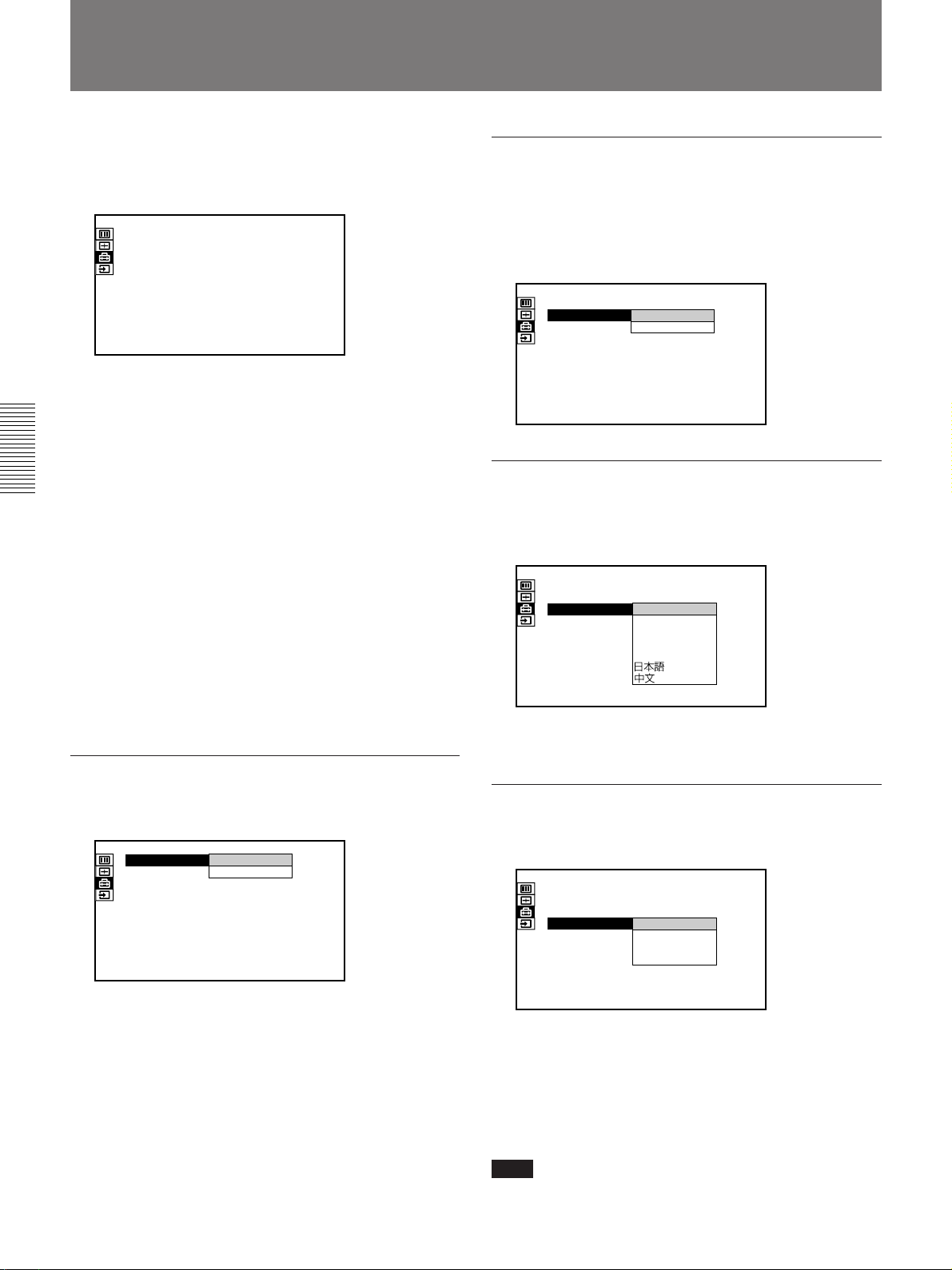
The SET SETTING Menu
The SET SETTING menu is used for changing the
initial settings of the projector. Unadjustable items are
not displayed in the menu.
SET SETTING
STATUS:AT
SPEAKER:
LANGUAGE:
INSTALLATION:
POWER SAVING
SIRCS RECEIVER
GROUP INDEX:
DEVICE INDEX:
ON
ON
ENGLISH
FLOOR-FRONT
OFF
:
:
FRONT&REAR
01
01
INPUT-A
Operation
1. Select an item
Use the V or v key to select the item, then press the
b key or the ENTER key.
2. Adjust an item
•When changing the adjustment level:
To increase the number, press the V or b key.
To decrease the number, press the v or B key.
Press the ENTER key to restore the original screen.
•When changing the setting:
Press the V or v key to change the setting, then press
the B or the ENTER key.
The original screen is restored.
STATUS
SPEAKER
Set to OFF to cut off the sound of the internal speaker
when external speakers are connected. When set to
OFF, “SPEAKER OFF” appears on the screen when
you turn on the power.
SET SETTING
STATUS:
SPEAKER:
LANGUAGE:
INSTALLATION:
POWER SAVING
SIRCS RECEIVER
GROUP INDEX:
DEVICE INDEX:
ON
ON
ON
ENGLISH
OFF
FLOOR-FRONT
OFF
:
FRONT&REAR
:
01
01
INPUT-A
LANGUAGE
Selects the language used in the menu and on-screen
displays.
SET SETTING
STATUS:
SPEAKER:
LANGUAGE:
INSTALLATION
POWER SAVING
SIRCS RECEIVER:
GROUP INDEX:
DEVICE INDEX:
ON
ON
ENGLISH
FLOOR-FRONT
:
FRANCAIS
CEILING-FRONT
DEUTSCH
: OFF
ITALIANO
FRONT&REAR
ESPANOL
01
01
Available languages are: English, French, German,
Italian, Spanish, Japanese and Chinese.
INPUT-A
Sets up the on-screen display.
SET SETTING
STATUS:
SPEAKER:
LANGUAGE:
INSTALLATION:
POWER SAVING
SIRCS RECEIVER
GROUP INDEX:
DEVICE INDEX:0101
ON
ON
OFF
ON
ENGLISH
FLOOR-FRONT
OFF
:
FRONT&REAR
:
INPUT-A
ON: Shows all of the on-screen displays.
OFF: Turns off the on-screen displays except for the
menus and warning messages.
30 (GB)
INSTALLATION
Reverses the picture horizontally or vertically.
SET SETTING
STATUS:
SPEAKER:
LANGUAGE:
INSTALLATION:
POWER SAVING:
SIRCS RECEIVER
GROUP INDEX:
DEVICE INDEX:
ON
ON
ENGLISH
FLOOR-FRONT
FLOOR-FRONT
CEILING-FRONT
FRONT&REAR
:
FLOOR-REAR
CEILING-REAR
01
01
FLOOR-FRONT: The picture is not reversed.
CEILING-FRONT: The picture is reversed
horizontally and vertically.
FLOOR-REAR:
The picture is reversed horizontally.
CEILING-REAR: The picture is reversed
vertically.
Note
In case of using a mirror, be careful of installation
since the picture may be reversed.
INPUT-A
OFF
Page 31
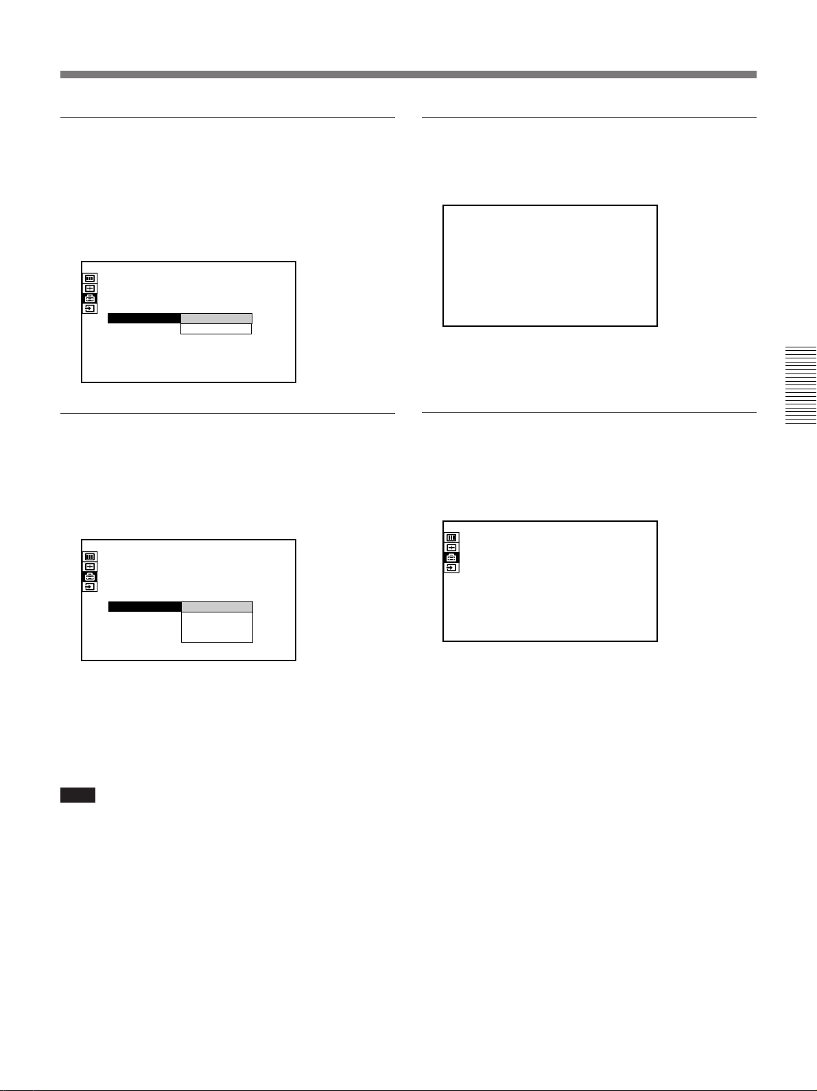
POWER SAVING
GROUP INDEX
When set to ON, the projector goes into the power
saving mode and the lamp for light source turns off if
no signal is input for about 10 minutes.
The power saving mode is canceled when a signal is
input or any key is pressed.
SET SETTING
STATUS:
SPEAKER:
LANGUAGE:
INSTALLATION:
POWER SAVING
SIRCS RECEIVER
GROUP INDEX:
DEVICE INDEX:0101
ON
ON
ENGLISH
FLOOR-FRONT
OFF
:
FRONT&REAR
:
ON
INPUT-A
OFF
SIRCS RECEIVER
Selects the remote control detectors to be activated.
Change the setting if the wireless Remote Commander
does not work properly due to the influence of the
fluorescent lamp, etc.
SET SETTING
STATUS:
SPEAKER:
LANGUAGE:
INSTALLATION:
POWER SAVING:
SIRCS RECEIVER
GROUP INDEX:
DEVICE INDEX:0101
ON
ON
ENGLISH
FLOOR-FRONT
OFF
FRONT&REAR
FRONT&REAR
:
FRONT
REAR
OFF
INPUT-A
Groups multiple projectors or switchers to operate
them simultaneously.
GROUP INDEX: 01
You can set the group index number to the desired
number between 01 and 99.
DEVICE INDEX
Displays the index number set with the INDEX
switches on the rear of the projector. You cannot set
the device index number with this menu.
SET SETTING
STATUS:
SPEAKER:
LANGUAGE:
INSTALLATION:
POWER SAVING:
SIRCS RECEIVER:
GROUP INDEX: 01
DEVICE INDEX:
ON
ON
ENGLISH
FLOOR-FRONT
OFF
FRONT&REAR
01
INPUT-A
FRONT & REAR: Activates both the front and rear
detectors.
FRONT: Activates the front detector only.
REAR: Activates the rear detector only.
OFF: Activates neither the front nor rear detector.
Note
When set to OFF, the wireless Remote Commander
does not function. Use the keys on the control panel or
the wired Remote Commander.
For details for setting the number, see page 45 (GB).
31 (GB)
Page 32
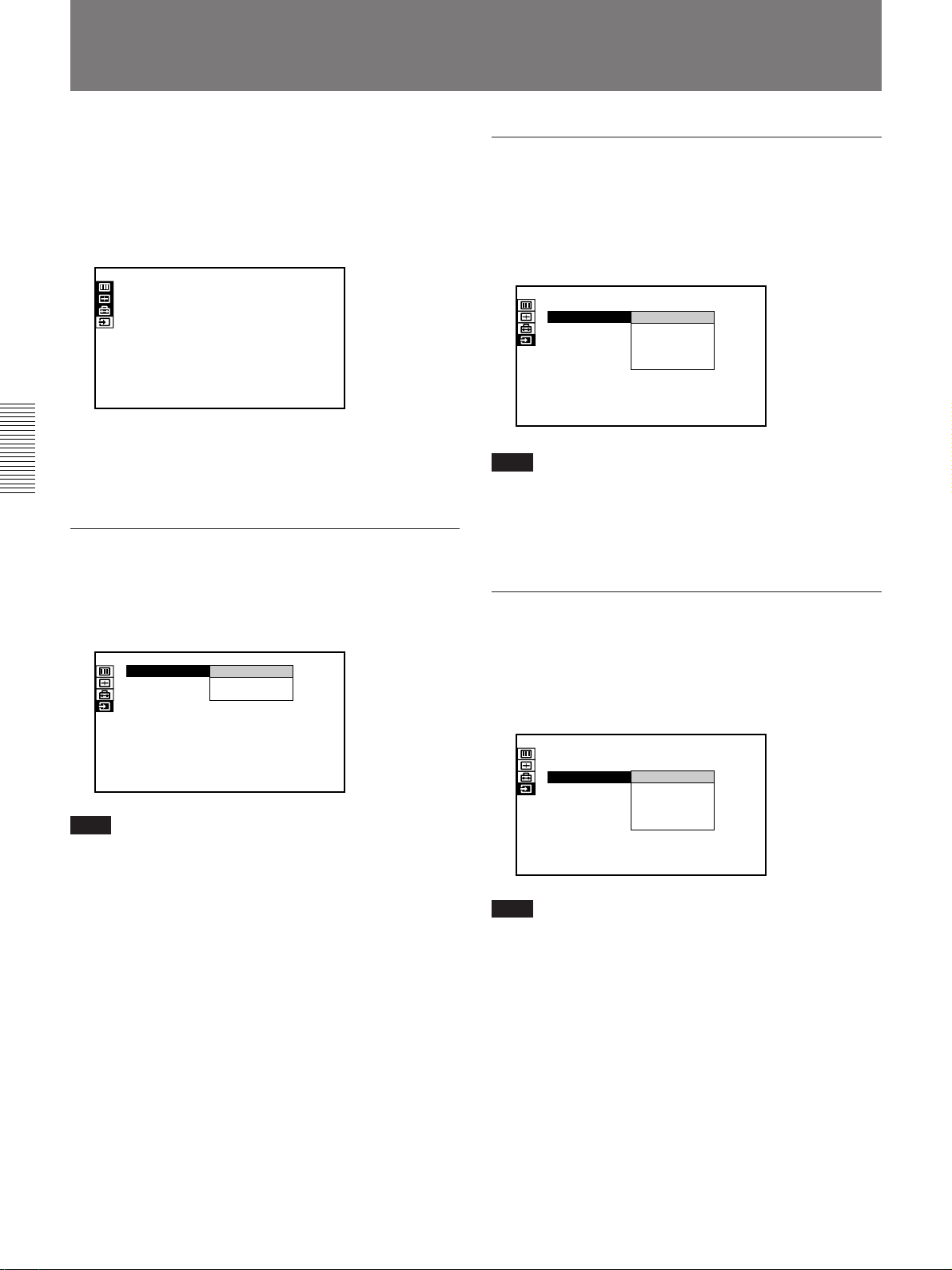
The SIGNAL SELECT Menu
The SIGNAL SELECT Menu is used for selecting the
input signal.
Depending on the interface board installed in the
projector, some items may not be displayed in the
menu.
SIGNAL SELECT
INPUT-A:
INPUT-B:
INPUT-C:
RGB
RGB
RGB
INPUT-A
Operation
Use the V or v key to select the input, then press the
ENTER key.
INPUT-A
Selects audio and video signals input from the INPUT
A connectors. You can select the RGB, component or
HDTV (YP
BPR) signal.
SIGNAL SELECT
INPUT-A:
INPUT-B:
INPUT-C:
RGB
RGB
COMPONENT
RGB
RGB
YP
INPUT-A
BPR
INPUT-B
Selects the input signal from the connectors on the
optional IFB-12A interface board installed in the
INPUT B section. You can select the RGB,
component, HDTV (YP
SIGNAL SELECT
INPUT-A:
INPUT-B:
INPUT-C:
Note
BPR), video or S video signal.
RGB
RGB
RGB
RGB
COMPONENT
VIDEO
S-VIDEO
YP
INPUT-B
BPR
This item is not displayed when the optional interface
board other than the IFB-12A is installed in the INPUT
B section, or when the output mode is selected on the
IFB-12A.
INPUT-C
Selects the input signal from the connectors on the
optional IFB-12A interface board installed in the
INPUT C section. You can select the RGB,
component, HDTV (YP
BPR), video or S video signal.
Note
When the PC-3000 signal interface switcher is
connected to the INPUT A connectors, you cannot
select the item.
SIGNAL SELECT
INPUT-A:
INPUT-B:
INPUT-C:
RGB
RGB
RGB
RGB
COMPONENT
VIDEO
S-VIDEO
YP
INPUT-C
BPR
Note
This item is not displayed when the optional interface
board other than the IFB-12A is installed in the INPUT
C section.
32 (GB)
Page 33
Installation Examples
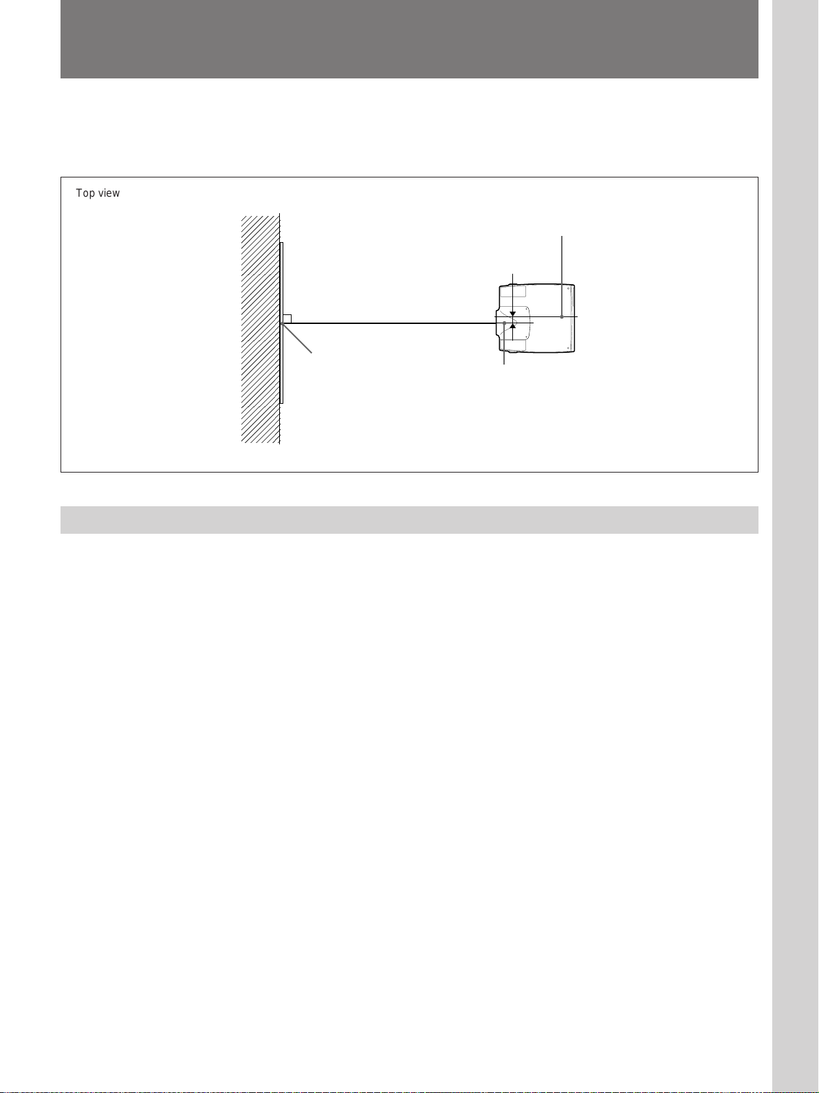
When you install the projector, be sure to adjust the horizontal positioning
of the projector so that the center of the lens is aligned with the horizontal
center of the screen.
Installation/Connection examples/Index number setting
Top view
Wall
About the Picture Size
Center of the projector
Screen
Cente of the screen
38 mm (1 1/2 inches)
Center of the lens
The on-screen picture size changes according to the setting of SCAN
CONV in the INPUT SETTING menu. Note that the projection distance
also changes depending on the picture size.
33 (GB)
Page 34
Installation Examples
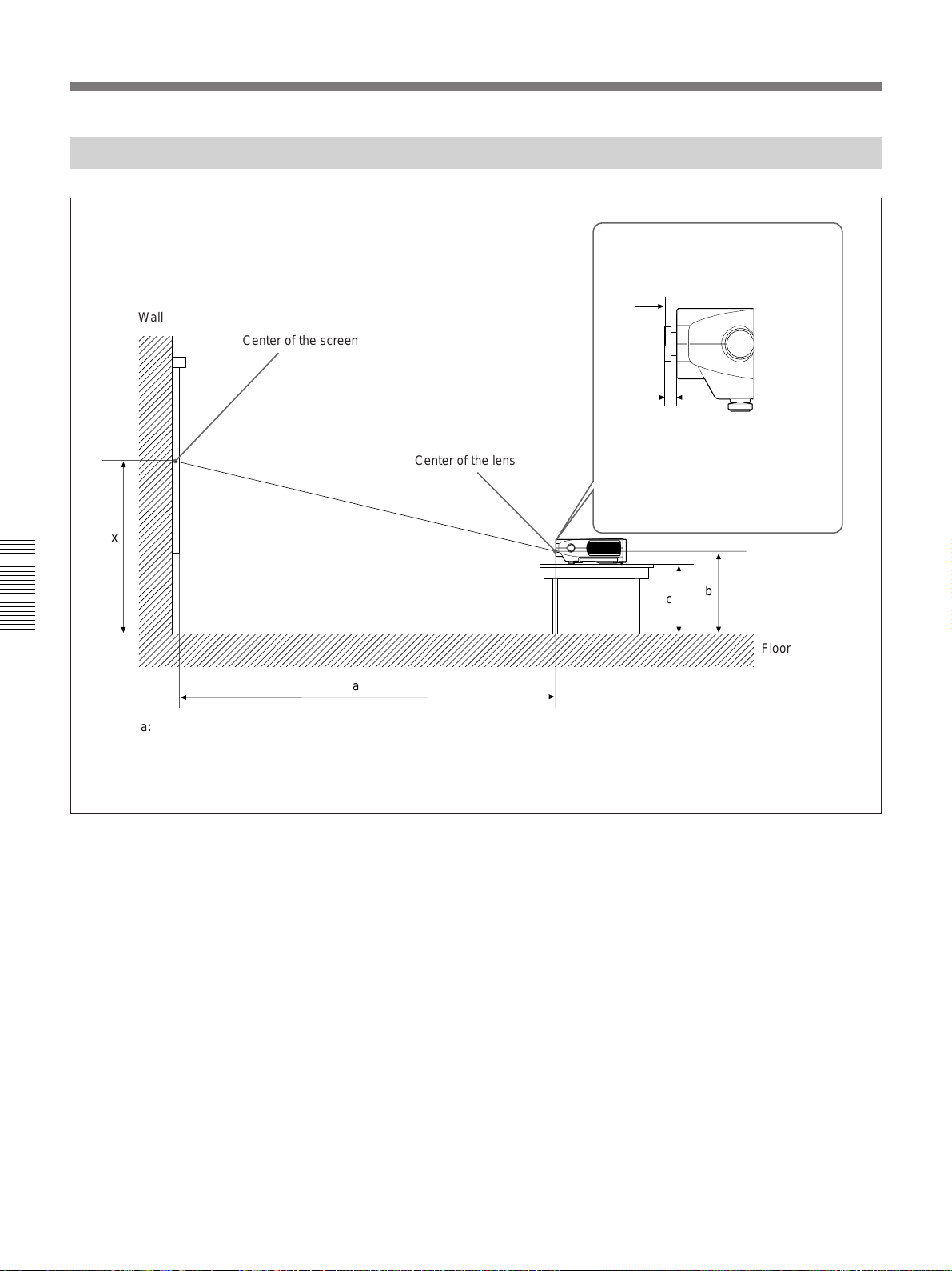
Floor Installation
Wall
Center of the screen
Center of the lens
Distance between the front of the cabinet
and the center of the lens
a
VPLL-2009: 70.6 mm (2 7/8 inches)
VPLL-2014: 63 mm (2 1/2 inches)
VPLL-Z2019: – 25.4 mm (– 1 inch)
VPLL-Z2025: 42.4 mm (1 11/16 inches)
VPLL-Z2039: 84.5 mm (3 3/8 inches)
VPLL-2075: 29.5 mm (1 3/16 inches)
x
a
a: distance between the screen and the center of the lens
b: distance between the floor and the center of the lens
c: distance between the floor and the bottom of the
adjusters of the projector
x: free
b
c
Floor
34 (GB)
Page 35
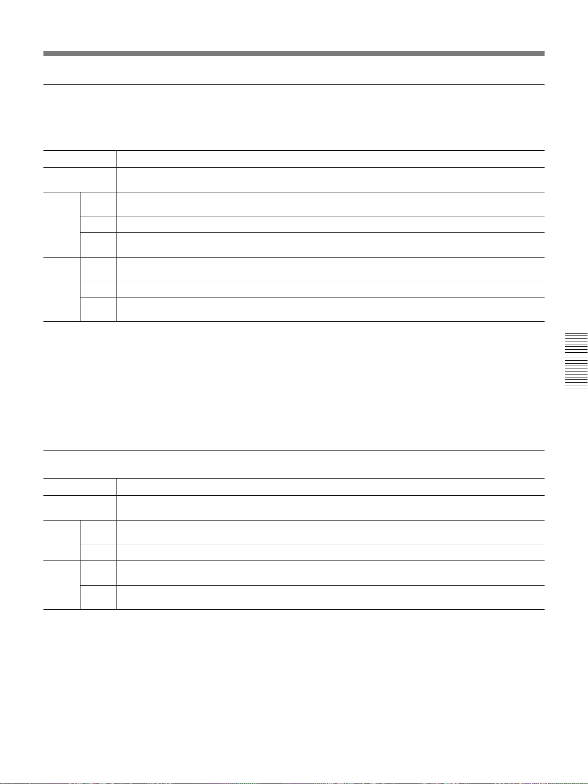
When using the VPLL-2009 fixed short focus lens
Make sure that the center of the lens is aligned with the vertical center of the screen.
Unit: mm (inches)
Screen size (inches) 40 80 100 120 150 180 200 250 300 350 400 450 500
a
Min.
b Center x
Max.
Min.
c Center x–142 (x–5 5/8)
Max.
To calculate the installation measurement (unit: mm)
SS: screen size measured diagonally (inches)
a = (SS × 35.079/1.814) – 134
b (minimum) = x – (SS/ 1.814 × 0.5)
b (maximum) = x + (SS/ 1.814 × 0.5)
c (minimum) = x – (SS/ 1.814 × 0.5 + 142.5)
c (maximum) = x – (SS/ 1.814 × – 0.5 + 141.5)
640 1410 1800 2190 2770 3350 3730 4700 5670 6630 7600 8570 9530
(25 1/4) (55 5/8) (70 7/8) (86 1/4) (109 1/8) (132) (146 7/8) (185 1/8) (223 3/8) (261 1/8) (299 1/4) (337 1/2) (375 1/4)
x–11 x–22 x–28 x–33 x–41 x–50 x–55 x–69 x–83 x–96 x–110 x–124 x–138
(x–7/16) (x–7/8) (x–1 1/8) (x–1 5/16)(x–1 11/16) (x–2) (x–2 1/4) (x–2 3/4) (x–3 3/8) (x–3 7/8) (x–4 3/8) (x–5) (x–5 1/2)
x+11 x+22 x+28 x+33 x+41 x+50 x+55 x+69 x+83 x+96 x+110 x+124 x+138
(x+7/16) (x+7/8) (x+1 1/8) (x+1 5/16)(x+1 11/16) (x+2) (x+2 1/4) (x+2 3/4) (x+3 3/8) (x+3 7/8) (x+4 3/8) (x+5) (x+5 1/2)
x–154 x–165 x–170 x–176 x–184 x–192 x–198 x–211 x–225 x–239 x–253 x–267 x–280
(x–6 1/8) (x–6 1/2) (x–6 3/4) (x–7) (x–7 1/4) (x–7 5/8) (x–7 7/8) (x–8 3/8) (x–8 7/8) (x–9 1/2) (x–10) (x–10 1/2)(x–11 1/8)
x–130 x–119 x–114 x–108 x–100 x–92 x–86 x–73 x–59 x–45 x–31 x–17 x–4
(x–5 1/4) (x–4 3/4) (x–4 1/2) (x–4 3/8) (x–4) (x–3 5/8) (x–3 1/2) (x–2 7/8) (x–2 3/8) (x–1 13/16) (x–1 1/4) (x–11/16) (x–5/32)
When using the VPLL-2014 fixed short focus lens
Unit: mm (inches)
Screen size (inches) 40 80 100 120 150 180 200 250 300 350 400 450 500
a
Min.
b
Max. x
Min.
c
Max.
To calculate the installation measurement (unit: mm)
SS: screen size measured diagonally (inches)
a = (SS × 52.244/1.814) – 123
b (minimum) = x – (SS/ 1.814 × 9.0)
c (minimum) = x – (SS/ 1.814 × 9.0 + 151.0)
1030 2180 2760 3330 4200 5060 5640 7080 8520 9960 11400 12840 14280
(40 5/8) (85 7/8) (108 3/4) (131 1/8) (165 3/8) (199 1/4) (222 1/8) (278 7/8) (335 1/2) (392 1/4) (448 7/8) (505 5/8) (562 3/8)
x–198 x–397 x–496 x–595 x–744 x–893 x–992 x–1240 x–1488 x–1736 x–1984 x–2232 x–2480
(x–
77/8) (x–
x–349 x–548 x–647 x–746 x–895 x–1044 x–1143 x–1391 x–1639 x–1887 x–2135 x–2383 x–2631
(x–13 7/8)(x–21 5/8)(x–25 1/2) (x–291/2)(x–35 1/4)(x–41 1/8)(x–45 1/8)(x–54 7/8)(x–64 5/8)(x–74 3/8)(x–841/8) (x–93 7/8)(x–103 5/8)
155/8) (x–19 5/8)(x–23 1/2)(x–29 3/8)(x–35 1/4)(x–39 1/8)(x–48 7/8)(x–58 5/8)(x–68 3/8)(x–78 1/4) (x–88) (x–97 3/4)
x–142
(x–5 5/8)
35 (GB)
Page 36
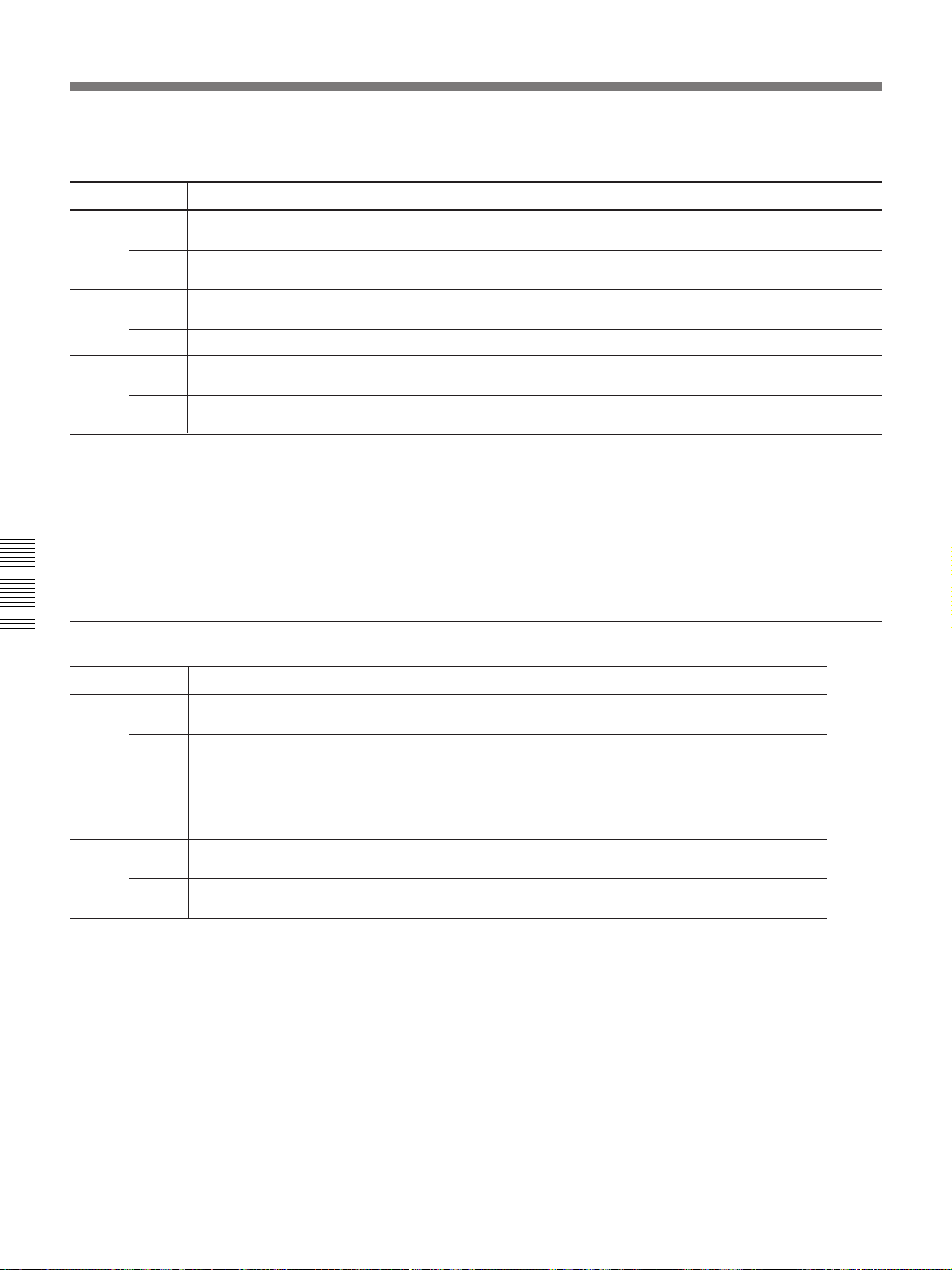
Installation Examples
When using the VPLL-Z2019 1.3-times zoom standard focus lens
Unit: mm (inches)
Screen size (inches) 40 80 100 120 150 180 200 250 300 350 400 450 500
Min.
a
Max.
Min.
b
Max. x
Min.
c
Max.
To calculate the installation measurement (unit: mm)
SS: screen size measured diagonally (inches)
a (minimum) = ((SS × 70.383/1.814) – 102) × 1.025
a (maximum) = ((SS × 92.644/1.814) – 104) × 0.975
b (minimum) = x – (SS/ 1.814 × 13.0)
c (minimum) = x – (SS/ 1.814 × 13.0 + 155.0)
1490 3080 3870 4670 5860 7050 7850 9840 11820 13810 15800 17790 19780
(58 3/4) (121 3/8) (152 1/2) (184) (230 3/4) (277 5/8) (309 1/8) (387 1/2) (465 1/2) (543 7/8) (622 1/8) (700 1/2) (778 7/8)
1890 3880 4880 5870 7370 8860 9860 12350 14840 17330 19810 22300 24790
(74 1/2) (152 7/8) (192 1/4) (2311/4) (290 1/4) (348 7/8) (388 1/4) (486 3/8) (584 3/8) (682 3/8) (780 1/8) (878 1/8) (976 1/8)
x–287 x–573 x–717 x–860 x–1075 x–1290 x–1433 x–1791 x–2150 x–2508 x–2866 x–3225 x–3583
(x–
113/8) (x–
x–442 x–728 x–872 x–1015 x–1230 x–1445 x–1588 x–1946 x–2305 x–2663 x–3021 x–3380 x–3738
(x–17 1/2)(x–28 3/4)(x–34 3/8) (x–40) (x–48 1/2) (x–57)
225/8) (x–28 1/4)(x–33 7/8)(x–42 3/8)(x–50 7/8)(x–56 1/2)(x–70 5/8)(x–84 3/4)(x–98 3/4)(x–112 7/8)(x–127)(x–141 1/8)
(x–62 5/8) (x–76 3/4) (x–90 3/4)(x–104 7/8)(x–11831/32)(x–133 1/8)
x–142
(x–5 5/8)
(x–1471/4)
When using the VPLL-Z2025 1.6-times zoom long focus lens
Unit: mm (inches)
Screen size (inches) 80 100 120 150 180 200 250 300 350 400 450 500
Min.
a
Max.
Min.
b
Max. x
Min.
c
Max.
To calculate the installation measurement (unit: mm)
SS: screen size measured diagonally (inches)
a (minimum) = ((SS × 92.078/1.814) – 176) × 1.025
a (maximum) = ((SS × 147.324/1.814) – 175) × 0.975
b (minimum) = x – (SS/ 1.814 × 13.0)
c (minimum) = x – (SS/ 1.814 × 13.0 + 155.0)
3980 5020 6060 7620 9180 10220 12830 15430 18030 20630 23230 25830
(156 3/4) (197 11/16) (238 5/8) (300 1/8) (361 1/2) (402 1/2) (505 1/4) (607 5/8) (709 15/16) (812 3/8) (914 3/4) (1017 1/8)
6160 7750 9330 11710 14080 15660 19620 23580 27540 31500 35460 39420
(242 5/8) (305 1/4) (367 3/8) (4611/8) (554 1/2) (616 5/8) (772 5/8) (928 1/2) (1084 1/2)(1240 3/8)(1396 1/4)(1552 1/4)
x–573 x–717 x–860 x–1075 x–1290 x–1433 x–1791 x–2150 x–2508 x–2866 x–3225 x–3583
(x–
225/8) (x–28 1/4)(x–33 7/8)(x–42 3/8)(x–50 7/8)(x–56 1/2)(x–70 5/8)(x–84 3/4)(x–98 3/4)(x–112 7/8)(x–127)(x–141 1/8)
x–728 x–872 x–1015 x–1230 x–1445 x–1588 x–1946 x–2305 x–2663 x–3021 x–3380 x–3738
(x–28 3/4)(x–34 3/8) (x–40) (x–48 1/2) (x–57)
(x–62 5/8) (x–76 3/4) (x–90 3/4) (x–104 7/8)(x–11831/32)(x–133 1/8)
x–142
(x–5 5/8)
(x–1471/4)
36 (GB)
Page 37
When using the VPLL-Z2039 1.5-times zoom long focus lens
Unit: mm (inches)
Screen size (inches) 80 100 120 150 180 200 250 300 350 400 450 500
Min.
a
Max.
Min.
b
Max. x
Min.
c
Max.
To calculate the installation measurement (unit: mm)
SS: screen size measured diagonally (inches)
a (minimum) = ((SS × 144.368/1.814) – 163) × 1.025
a (maximum) = ((SS × 216.549/1.814) – 163) × 0.975
b (minimum) = x – (SS/ 1.814 × 13.0)
c (minimum) = x – (SS/ 1.814 × 13.0 + 155.0)
6360 7990 9620 12070 14510 16150 20220 24300 28380 32460 36540 40620
(250 1/2) (314 5/8) (378 7/8) (475 3/8) (571 3/8) (636) (796 1/4) (956 7/8) (1117 1/2)(1278 1/8)(1438 7/8)(1599 1/2)
9150 11480 13810 17300 20790 23120 28940 34760 40570 46390 52210 58030
(360 3/8) (452 1/8) (543 7/8) (6811/4) (818 5/8) (910 3/8) (1139 5/8)(1368 3/4)(1597 1/2)(1826 5/8)(2055 7/8)(2284 15/16)
x–573 x–717 x–860 x–1075 x–1290 x–1433 x–1791 x–2150 x–2508 x–2866 x–3225 x–3583
(x–
225/8) (x–28 1/4)(x–33 7/8)(x–42 3/8)(x–50 7/8)(x–56 1/2)(x–70 5/8)(x–84 3/4)(x–98 3/4)(x–112 7/8)(x–127)(x–141 1/8)
x–728 x–872 x–1015 x–1230 x–1445 x–1588 x–1946 x–2305 x–2663 x–3021 x–3380 x–3738
(x–28 3/4)(x–34 3/8) (x–40) (x–48 1/2) (x–57)
(x–62 5/8) (x–76 3/4) (x–90 3/4)(x–104 7/8)(x–11831/32)(x–133 1/8)
x–142
(x–5 5/8)
(x–1471/4)
When using the VPLL-2075 fixed long focus lens
Unit: mm (inches)
Screen size (inches) 80 100 120 150 180 200 250 300 350 400 450 500
a
Min.
b
Max. x
Min.
c
Max.
To calculate the installation measurement (unit: mm)
SS: screen size measured diagonally (inches)
a = (SS × 269.100/1.814) + 163
b (minimum) = x – (SS/ 1.814 × 13.0)
c (minimum) = x – (SS/ 1.814 × 13.0 + 155.0)
12030 15000 17960 22410 26860 29830 37250 44660 52080 59500 66910 74330
(473 11/16) (590 5/8) (707 1/4) (882 1/2) (1057 5/8)(1174 5/8)(1466 3/4)(1758 1/2)(2050 3/4)(2342 7/8)(2634 5/8)(2926 3/4)
x–573 x–717 x–860 x–1075 x–1290 x–1433 x–1791 x–2150 x–2508 x–2866 x–3225 x–3583
(x–
225/8) (x–
x–728 x–872 x–1015 x–1230 x–1445 x–1588 x–1946 x–2305 x–2663 x–3021 x–3380 x–3738
(x–28 3/4)(x–34 3/8) (x–40) (x–48 1/2) (x–57)
281/4) (x–33 7/8)(x–42 3/8)(x–50 7/8)(x–56 1/2)(x–70 5/8)(x–84 3/4)(x–98 3/4)(x–112 7/8)(x–127)(x–141 1/8)
(x–62 5/8) (x–76 3/4) (x–90 3/4)(x–104 7/8)(x–11831/32)(x–1331/8)(x–147 1/4)
x–142
(x–5 5/8)
37 (GB)
Page 38
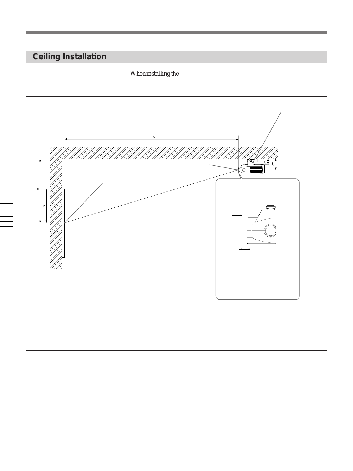
Installation Examples
Ceiling Installation
Center of the screen
x
e
When installing the projector on the ceiling, use the PSS-2000 Projector
Suspension Support.
For ceiling installation, ask for qualified Sony personnel only.
PSS-2000 Projector Suspension Support
(not supplied)
a
Ceiling
c
Center of the lens
Distance between the front of the
cabinet and the center of the lens
a
b
VPLL-2014: 63 mm (2 1/2 inches)
VPLL-Z2019: – 25.4 mm (– 1 inch)
Wall
a: Distance between the screen and the center of the lens
b: Distance between the ceiling and the center of the lens
c: Distance between the ceiling and the mounting surface of the suspension bracket
e: Distance between the top of the available screen range and the center of the screen
x: Distance between the ceiling and the center of the screen
VPLL-Z2025: 42.4 mm (1 11/16 inches)
VPLL-Z2039: 84.5 mm (3 3/8 inches)
VPLL-2075: 29.5 mm (1 3/16 inches)
38 (GB)
Page 39
When using the VPLL-2014 fixed short focus lens
Unit: mm (inches)
Screen size (inches) 40 80 100 120 150 180 200 250 300 350 400 450 500
a
Min.
b
Max.
e
Min.
x
Max.
When using the PSS-2000 Projector Suspension Support: c =104.7 (4 1/8), x (minimum) = e
To calculate the installation measurement (unit: mm)
SS: screen size measured diagonally (inches)
a = (SS × 52.244/1.814) – 123
e = SS × 0.3 × 25.4
x (maximum) = c + (SS/1.814 × 9.0 + 139.6)
1030 2180 2760 3330 4200 5060 5640 7080 8520 9960 11400 12840 14280
(40 5/8) (85 7/8) (108 3/4) (131 1/8) (165 3/8) (199 1/4) (222 1/8) (278 7/8) (335 1/2) (392 1/4) (448 7/8) (505 5/8) (562 3/8)
c+131
(c+5 1/4)
c+140
(c+5 1/2)
305 610 762 914 1143 1372 1524 1905 2286 2667 3048 3429 3810
(12 1/8) (24 1/8) (30) (36) (45) (54 1/8) (60) (75 1/8) (90 1/8) (105 1/8) (120 1/16) (135 1/8) (150 1/8)
c+131
(c+5 1/4)
c+338 c+536 c+636 c+735 c+884 c+1033 c+1132 c+1380 c+1628 c+1876 c+2124 c+2372 c+2620
(c+13 3/8)(c+21 1/8)(c+25 1/8) (c+29) (c+34 7/8)(c+40 3/4)(c+44 5/8)(c+54 3/8)(c+64 1/8)(c+73 7/8)(c+83 3/4)(c+93 1/2)(c+103 1/4)
When using the VPLL-Z2019 1.3-times zoom standard focus lens
Unit: mm (inches)
Screen size (inches) 40 80 100 120 150 180 200 250 300 350 400 450 500
Min.
a
Max.
Min.
b
Max.
e
Min.
x
Max.
When using the PSS-2000 Projector Suspension Support: c =104.7 (4 1/8), x (minimum) = e
To calculate the installation measurement (unit: mm)
SS: screen size measured diagonally (inches)
a (minimum) = ((SS × 70.383/1.814) – 102) × 1.025
a (maximum) = ((SS × 92.644/1.814) – 104) × 0.975
e = SS × 0.3 × 25.4
x (maximum) = c + (SS/1.814 × 13.0 + 143.6)
1490 3080 3870 4670 5860 7050 7850 9840 11820 13810 15800 17790 19780
(58 3/4) (121 3/8) (152 1/2) (184) (230 3/4) (277 5/8) (309 1/8) (387 1/2) (465 1/2) (543 7/8) (622 1/8) (700 1/2) (778 7/8)
1890 3880 4880 5870 7370 8860 9860 12350 14840 17330 19810 22300 24790
(74 1/2) (152 7/8) (192 1/4) (2311/4) (290 1/4) (348 7/8) (388 1/4) (486 3/8) (584 3/8) (682 3/8) (780 1/8) (878 1/8) (976 1/8)
c+131
(c+5 1/4)
c+144
(c+5 3/4)
305 610 762 914 1143 1372 1524 1905 2286 2667 3048 3429 3810
(12 1/8) (24 1/8) (30) (36) (45) (54 1/8) (60) (75 1/8) (90 1/8) (105 1/8) (120 1/16) (135 1/8) (150 1/8)
c+131
(c+5 1/4)
c+430 c+717 c+860 c+1003 c+1218 c+1433 c+1577 c+1935 c+2293 c+2652 c+3010 c+3368 c+3726
(c+17) (c+28 1/4)(c+33 7/8)(c+39 1/2) (c+48)
(c+56 1/2) (c+62 1/8) (c+76 1/4) (c+90 3/8)(c+104 1/2)(c+118 5/32)(c+132 5/8)(c+146 3/4)
39 (GB)
Page 40
Installation Examples
When using the VPLL-Z2025 1.6-times zoom long focus lens
Unit: mm (inches)
Screen size (inches) 80 100 120 150 180 200 250 300 350 400 450 500
Min.
a
Max.
Min.
b
Max.
e
Min.
x
Max.
When using the PSS-2000 Projector Suspension Support: c =104.7 (4 1/8), x (minimum) = e
To calculate the installation measurement (unit: mm)
SS: screen size measured diagonally (inches)
a (minimum) = ((SS × 92.078/1.814) – 176) × 1.025
a (maximum) = ((SS × 147.324/1.814) – 175) × 0.975
e = SS × 0.3 × 25.4
x (maximum) = c + (SS/1.814 × 13.0 + 143.6)
3980 5020 6060 7620 9180 10220 12830 15430 18030 20630 23230 25830
(156 3/4) (197 11/16) (238 5/8) (300 1/8) (361 1/2) (402 1/2) (505 1/4) (607 5/8) (709 15/16) (812 3/8) (914 3/4) (1017 1/8)
6160 7750 9330 11710 14080 15660 19620 23580 27540 31500 35460 39420
(242 5/8) (305 1/4) (367 3/8) (4611/8) (554 1/2) (616 5/8) (772 5/8) (928 1/2) (1084 1/2)(1240 3/8)(1396 1/4)(1552 1/4)
c+131
(c+5 1/4)
c+144
(c+5 3/4)
610 762 914 1143 1372 1524 1905 2286 2667 3048 3429 3810
(24 1/8) (30) (36) (45) (54 1/8) (60) (75 1/8) (90 1/8) (105 1/8) (120 1/16) (135 1/8) (150 1/8)
c+131
(c+5 1/4)
c+717 c+860 c+1003 c+1218 c+1433 c+1577 c+1935 c+2293 c+2652 c+3010 c+3368 c+3726
(c+28 1/4)(c+33 7/8)(c+39 1/2) (c+48)
(c+56 1/2) (c+62 1/8) (c+76 1/4) (c+90 3/8)(c+104 1/2)(c+118 5/32)(c+132 5/8)(c+146 3/4)
When using the VPLL-Z2039 1.5-times zoom long focus lens
Screen size (inches) 80 100 120 150 180 200 250 300 350 400 450 500
Min.
a
Max.
Min.
b
Max.
e
Min.
x
Max.
When using the PSS-2000 Projector Suspension Support: 104.7 (4 1/8), x (minimum) = e
6360 7990 9620 12070 14510 16150 20220 24300 28380 32460 36540 40620
(250 1/2) (314 5/8) (378 7/8) (475 3/8) (571 3/8) (636) (796 1/4) (956 7/8) (1117 1/2)(1278 1/8)(1438 7/8)(1599 1/2)
9150 11480 13810 17300 20790 23120 28940 34760 40570 46390 52210 58030
(360 3/8) (452 1/8) (543 7/8) (6811/4) (818 5/8) (910 3/8) (1139 5/8)(1368 3/4)(1597 1/2)(1826 5/8)(2055 7/8)(2284 15/16)
c+131
(c+5 1/4)
c+144
(c+5 3/4)
610 762 914 1143 1372 1524 1905 2286 2667 3048 3429 3810
(24 1/8) (30) (36) (45) (54 1/8) (60) (75 1/8) (90 1/8) (105 1/8) (120 1/16) (135 1/8) (150 1/8)
c+131
(c+5 1/4)
c+717 c+860 c+1003 c+1218 c+1433 c+1577 c+1935 c+2293 c+2652 c+3010 c+3368 c+3726
(c+28 1/4)(c+33 7/8)(c+39 1/2) (c+48)
(c+56 1/2) (c+62 1/8) (c+76 1/4) (c+90 3/8)(c+104 1/2)(c+118 5/32)(c+132 5/8)(c+146 3/4)
Unit: mm (inches)
To calculate the installation measurement (unit: mm)
SS: screen size measured diagonally (inches)
a (minimum) = ((SS × 144.368/1.814) – 163) × 1.025
a (maximum) = ((SS × 216.549/1.814) – 163) × 0.975
e = SS × 0.3 × 25.4
x (maximum) = c + (SS/1.814 × 13.0 + 143.6)
40 (GB)
Page 41
When using the VPLL-2075 fixed long focus lens
Screen size (inches) 80 100 120 150 180 200 250 300 350 400 450 500
a
Min.
b
Max.
e
Min.
x
Max.
When using the PSS-2000 Projector Suspension Support: c =104.7 (4 1/8), x (minimum) = e
12030 15000 17960 22410 26860 29830 37250 44660 52080 59500 66910 74330
(473 11/16) (590 5/8) (707 1/4) (882 1/2) (1057 5/8)(1174 5/8)(1466 3/4)(1758 1/2)(2050 3/4)(2342 7/8)(2634 5/8)(2926 3/4)
c+131
(c+5 1/4)
c+144
(c+5 3/4)
610 762 914 1143 1372 1524 1905 2286 2667 3048 3429 3810
(24 1/8) (30) (36) (45) (54 1/8) (60) (75 1/8) (90 1/8) (105 1/8) (120 1/16) (135 1/8) (150 1/8)
c+131
(c+5 1/4)
c+717 c+860 c+1003 c+1218 c+1433 c+1577 c+1935 c+2293 c+2652 c+3010 c+3368 c+3726
(c+28 1/4)(c+33 7/8)(c+39 1/2) (c+48)
(c+56 1/2) (c+62 1/8) (c+76 1/4) (c+90 3/8)(c+104 1/2)(c+118 5/32)(c+132 5/8)(c+146 3/4)
Unit: mm (inches)
To calculate the installation measurement (unit: mm)
SS: screen size measured diagonally (inches)
a = (SS × 269.100/1.814) + 163
e = SS × 0.3 × 25.4
x (maximum) = c + (SS/1.814 × 13.0 + 143.6)
41 (GB)
Page 42
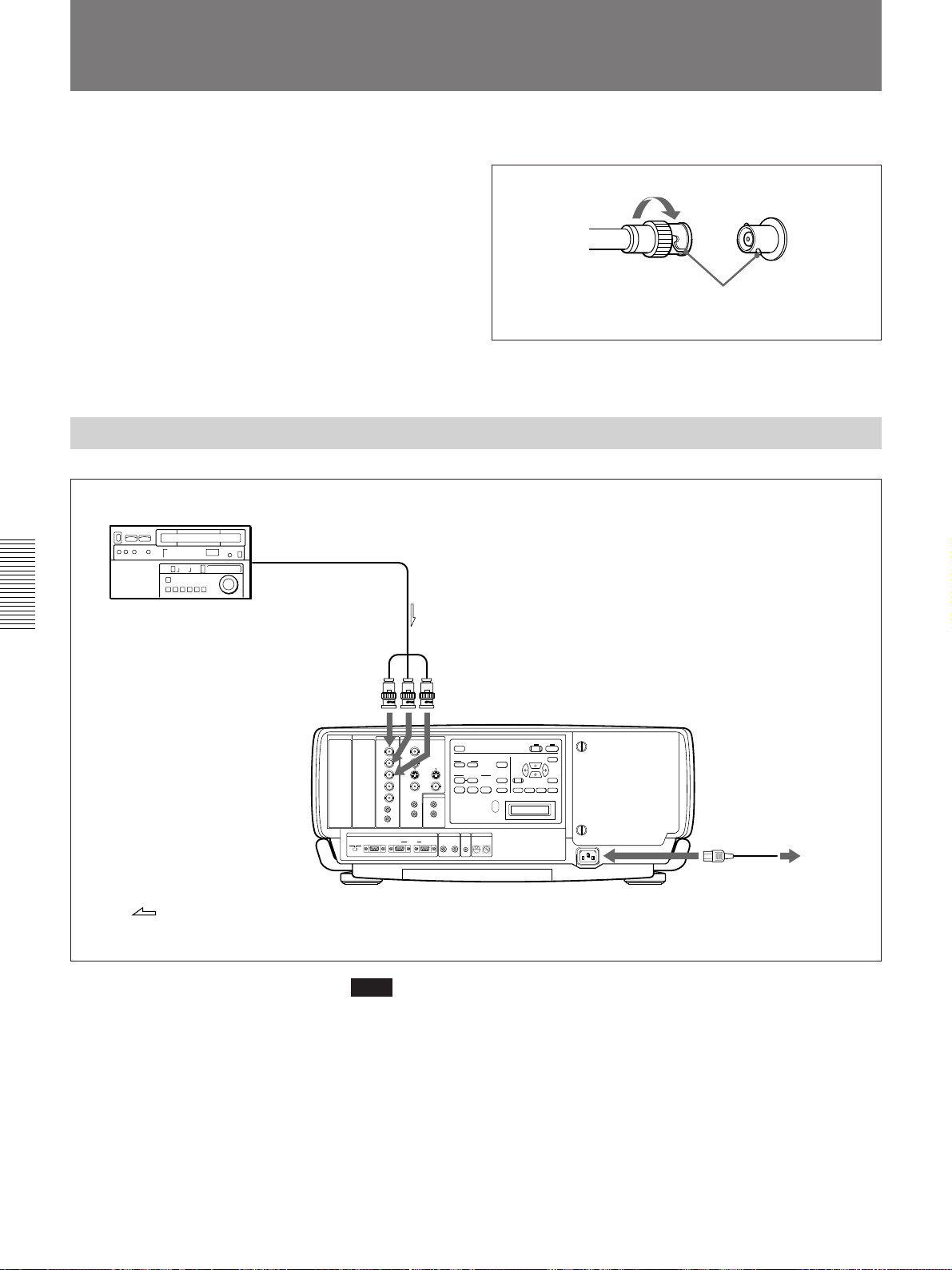
Connection Examples
For details on how to connect a computer, VCR or external
Connecting a BNC connector
active speakers, see page 20 (GB). Also refer to the
instruction manual of the equipment to be connected.
2 Turn to the right.
When making connections, be sure to:
•turn off all equipment before making any
connections.
•use the proper cables for each connection.
•insert the plugs of the cables properly; plugs that are
not fully inserted may generate noise. When pulling
out a cable, be sure to pull it out from the plug, not
the cable itself.
Connecting 15k RGB/Component Equipment
15k RGB/component
equipment
to RGB/component output
1 Align the pins with the pin holes
and push in the plug into the
socket.
:
Signal flow
Monitor cable
(BNC type)
Rear
INPUT C INPUT B
INPUT A VIDEO
AUDIO OUT
REMOTE CONTROL S TRIG
DEVICE INDEX
0
+
–
1
AC power cord
to AC IN
(supplied)
Note
Switch the input signal with the INPUT-A item in the SIGNAL SELECT
menu.
For details, see page 32 (GB).
to a wall outlet
42 (GB)
Page 43
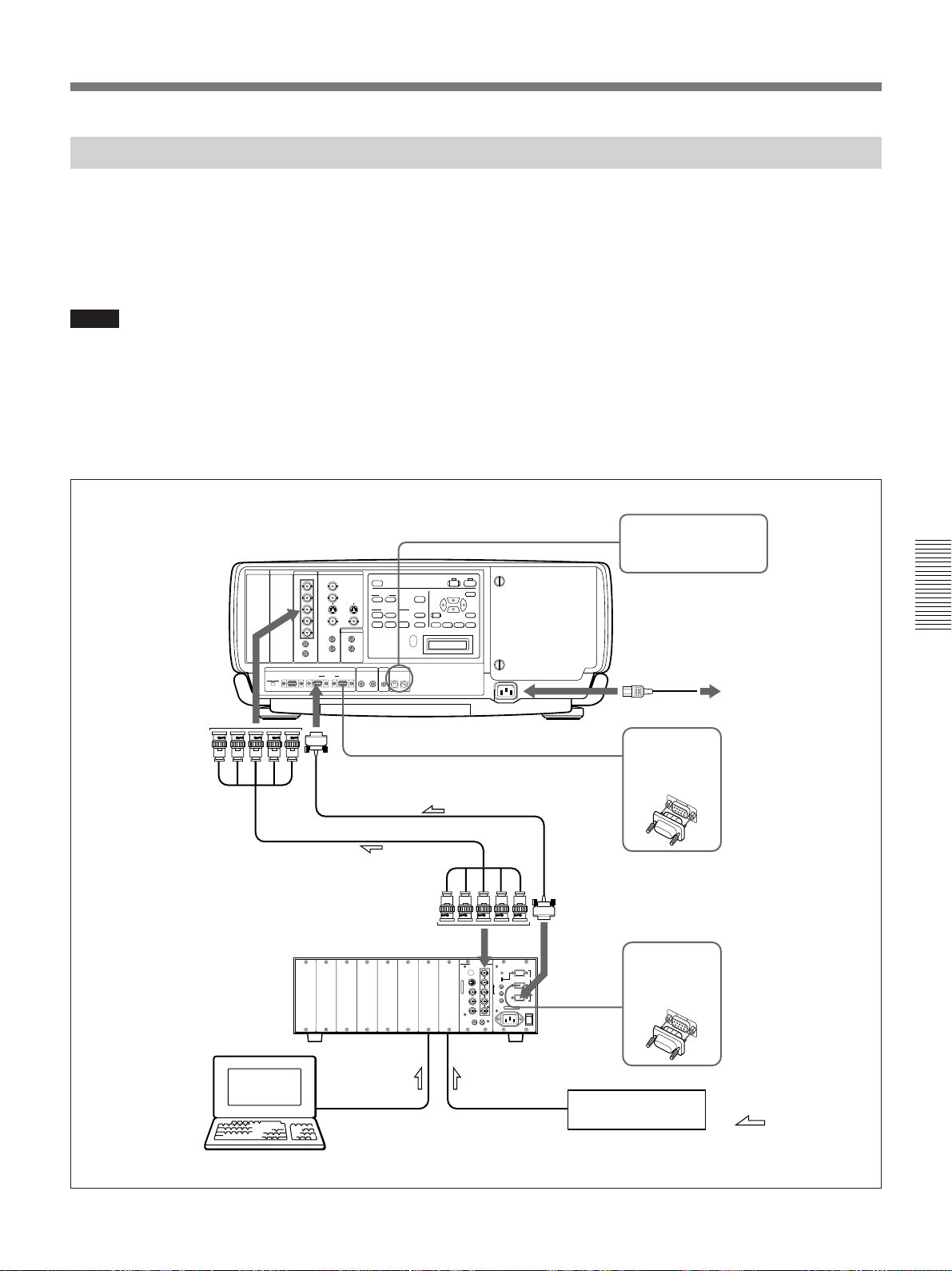
Connecting the Switcher
Use the optional PC-3000 Signal Interface Switcher
for connecting various video equipment. The input can
be selected by pressing the SWITCHER/VIDEO
MEMORY/INDEX keys on the Remote Commander.
For selecting the input from the switcher, see page 15 (GB).
Notes
•When you select the input from the switcher, be sure
to set the SWITCHER/VIDEO MEMORY/INDEX
select switch to the SWITCHER position.
Rear
INPUT C INPUT B
INPUT A VIDEO
AUDIO OUT
REMOTE CONTROL S TRIG
DEVICE INDEX
0
+
–
1
•When connecting the switcher, use the wired Remote
Commander. If you use the wireless Remote
Commander, activate the remote control detector on
only one unit of the equipment connected through the
PJ COM connector. For the other equipment, set
SIRCS RECEIVER in the SET SETTING menu to
OFF to deactivate the remote control detectors.
For details, see page 31 (GB).
•After all the connections are complete, attach the
terminator (supplied) to the PJ COM connector on
both the projector and switcher to which nothing is
connected.
Device index number: 01
AC power cord
(supplied)
to the wall outlet
to INPUT A
to PJ COM IN
SIC-10 connecting cable
(5BNC ˜ 5BNC)
(not supplied)
PC-3000 switcher
Computer, etc.
to OUTPUT
to AC IN
RCC-5G/10G/30G
connecting cable
(not supplied)
OUT PUT
RS-232C/422A
SW NO
RS-232C
REMOTE
RS-422A
RS-485 IN
RS-485 OUT
Attach the
supplied
terminator.
to PJ COM OUT
Attach the
terminator
(supplied with
the PC-3000).
VCR, etc.
:
Signal flow
43 (GB)
Page 44
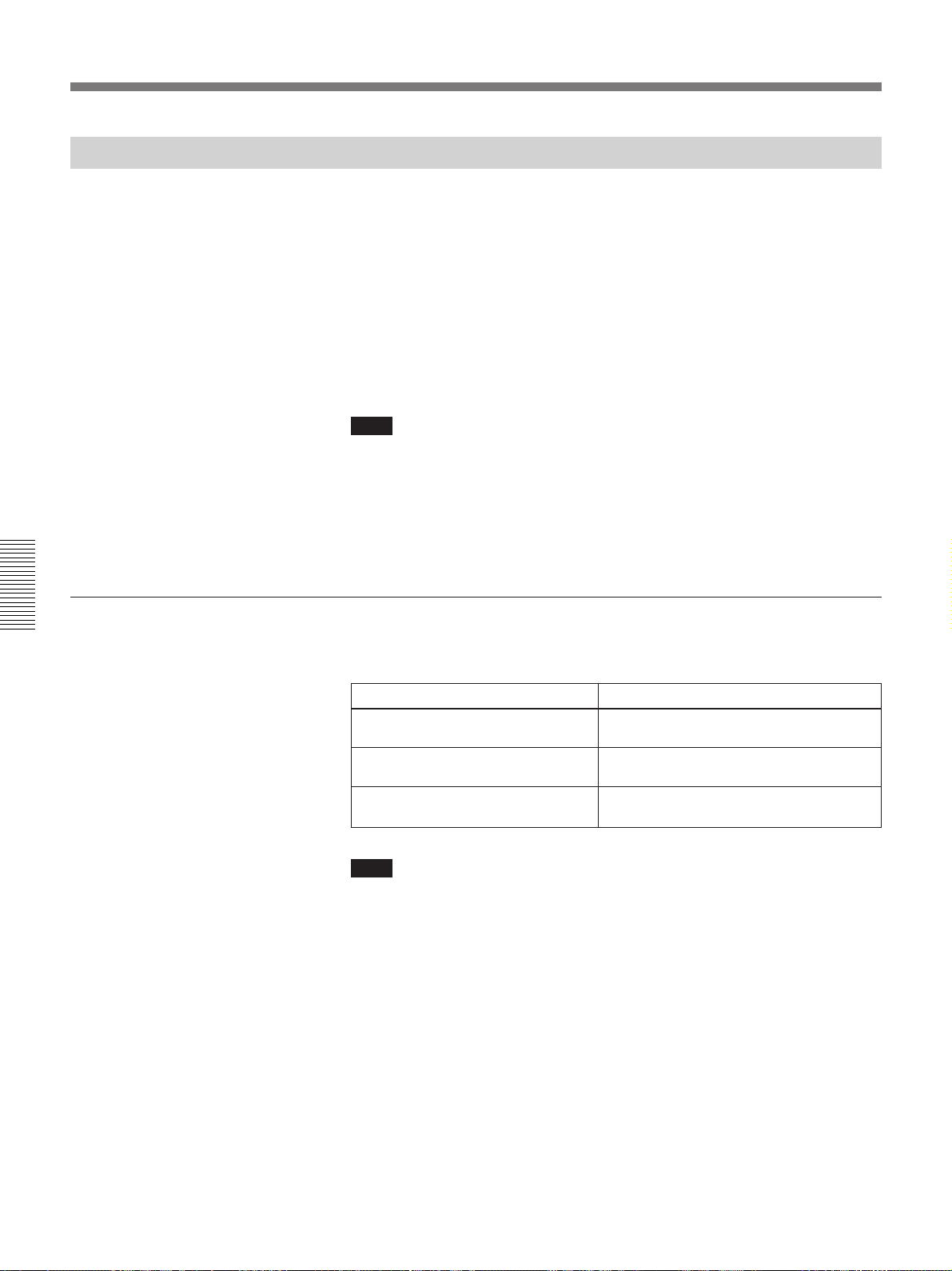
Connection Examples
Confirming the System Construction
After all the connections are complete, confirm that equipment of the
system is properly setup.
1 Connect the AC cords of all equipment to the AC outlets.
2 Press the SYS SET key on the Remote Commander.
You can also press the LIGHT and RESET keys simultaneously on the
control panel for the same effect.
Information on the system construction and the settings of the interface
boards, etc. are automatically confirmed. Then the message disappears.
Note
When you want to use the projector without connecting the switcher after
using the switcher in the system connections, it is necessary to confirm the
system construction again by pressing the SYS SET key or the LIGHT and
RESET keys after all the connections are complete. If you press the key(s),
“Master Switcher not exist” appears, but the system construction is
automatically recognized.
When a system error is detected
The following messages are displayed on the screen and display window:
If the switcher is in standby mode, the message appears only in the
message display window.
Message
Master Switcher not exist.
Same DEVICE INDEX for Projector
detected.
Same DEVICE INDEX for Switcher
detected.
Note
Remedy
Set the switcher that outputs the signal to
the projector to number 1.
Change either number of the projectors
that have the same number.
Change either number of the switchers
that have the same number.
44 (GB)
Page 45
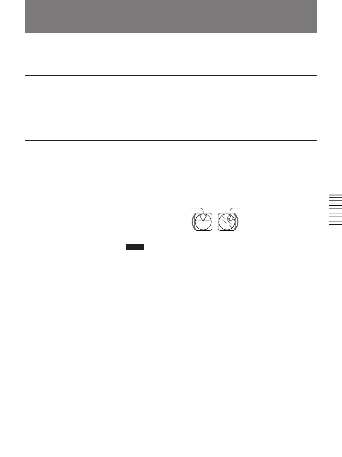
Setting the Index Numbers
When you connect multiple projectors in your system, you have to set the
group index and device index numbers for each projector.
To set the group index number
If you set the same group index number for multiple projectors, you can
operate multiple projectors and switchers simultaneously (such as input
selection) by designating the number.
The group index number can be set in the menu.
For group index number setting, see page 31 (GB).
To set the device index number
If you set the device index number, you can control each projector
individually with the supplied Remote Commander.
The device index number can be set with the DEVICE INDEX switches on
the rear of the projector. It is set to “01” at the factory.
If only one projector is connected, set it to “01.”
Ten’s digit Unit’s digit
0
Notes
•Do not set the same device index number for the projectors in the same
system.
•Do not set the number to “00.” If you do, the projector will be operated
only with the keys on the control panel. It cannot be controlled with the
wired or wireless Remote Commander, or with an external equipment to
which the PJ COM connectors are connected.
1
45 (GB)
Page 46
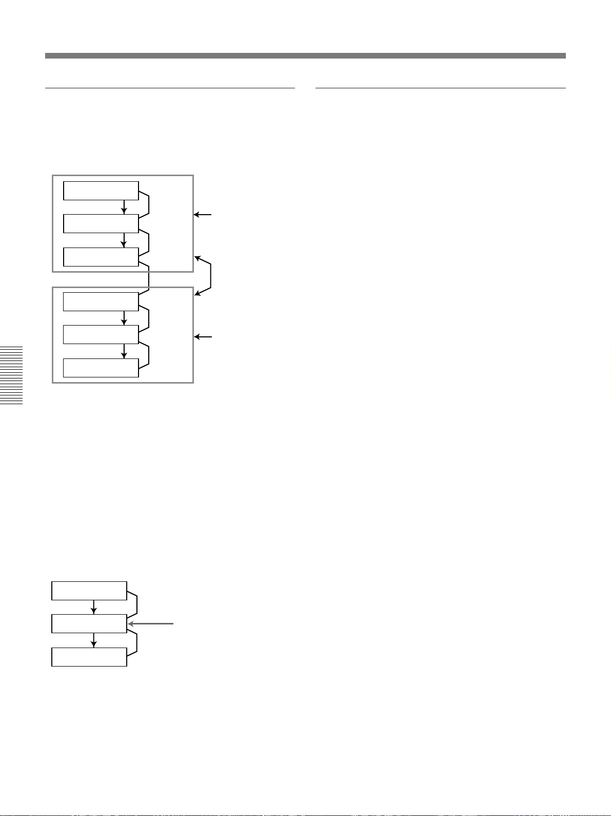
Setting the Index Numbers
Notes on setting of the index number
•Set the same group index number for all
equipment of the same system connection (those
on the signal route between the signal source and
the projector).
PC-3000
Signal flow
PC-3000
Signal flow
Projector
PC-3000
Signal flow
Projector
Signal flow
Projector
PJ COM
Set the same group
index number.
PJ COM
Set the different
group index number
for two systems.
PJ COM
Set the same group
index number.
PJ COM
Notes on connections when two or more
switchers are used
•Mount the IFB-12A interface board to the slot 1 of
the number n switcher and connect the output
connector of the number (n+1) switcher to the
IFB-12A.
•You can attach the IFB-12A signal interface board
(when the IN/OUT switch is set to OUT) only to
the number 1 switcher.
For setting the group index number, see “GROUP INDEX”
on page 31 (GB).
•Set the correct group and device index numbers
and the switcher number.
Do not set the same device index number or the same
switcher number in one group.
For example, if there are different pieces of
equipment with the switcher number 1, the error
message will appear when the SYS SET key is
pressed.
•Set the switcher that outputs the signal to the
projector to number 1.
PC-3000
PC-3000
Projector
Set this switcher to 1.
46 (GB)
Page 47
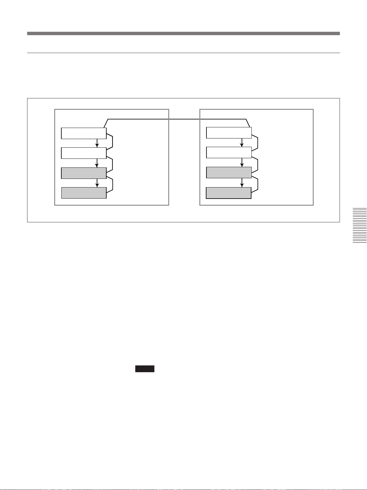
To select the projector by designating the index numbers
When the switchers and projectors are connected as illustrated, select the
desired projector by pressing the keys on the Remote Commander as
shown below.
PJ COM
PC-3000
Signal flow
PC-3000
Signal flow
Projector A
Signal flow
Projector B
Number 2 switcher
PJ COM
Number 1 switcher
PJ COM
Device index 01
PJ COM
Device index 02
Example:
To select all the projectors
To select projectors with device index 01 from all the groups
To select a projector with device index 01 from group index 02
PC-3000
Signal flow
PC-3000
Signal flow
Projector C
Signal flow
Projector D
Group index 02Group index 01
Number 2 switcher
PJ COM
Number 1 switcher
PJ COM
Device index 01
PJ COM
Device index 02
GROUP n ALL n ENTER n ALL n ENTER
Projectors A, B, C and D are selected.
GROUP n ALL n ENTER n 1 n ENTER
Projectors A and C are selected.
GROUP n 2 n ENTER n 1 n ENTER
Projector C is selected.
To select all the projectors from group index 02
GROUP n 2 n ENTER n ALL n ENTER
Projectors C and D are selected.
Notes
•Set the group index and device index numbers correctly. If more than two
projectors are set to the same group index and device index numbers, an
error message will be displayed when the SYS SET key is pressed.
•If the group index is a tens digit number, press the GROUP key before
each press of the number key.
Example:
To select a projector with device index 13 of group index 12
GROUP n 1 n GROUP n 2 n ENTER n 1 n 3 n ENTER
47 (GB)
Page 48
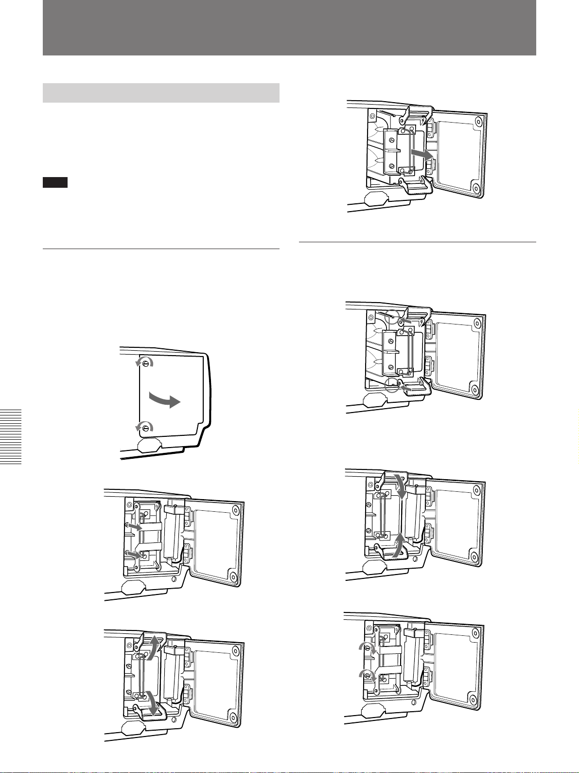
Maintenance
Replacing the Lamp
When the lamp has burnt out, the LAMP FAIL
indicators at the rear of the projector light. In this case,
replace the lamp with a new LMP-Q2000 Projector
Lamp (not supplied).
Note
Immediately after turning off the power, the lamp is
extremely hot. Wait at least one hour before changing
the lamp to give it enough time to cool down.
To remove the lamp
1 Press the STANDBY key to set the projector to
standby mode, and unplug the power cord.
2 Remove the two screws with a coin or similar
object, or a screwdriver, to open the lamp cover.
5 Pull out the lamp by holding the handles.
To install a new lamp
1 Mount the lamp with the grooves on the top and
bottom aligned with the guides on the projector.
3 Loosen the two screws that fasten the lamp.
4 Fold out the levers up and down.
2 Push the lamp completely until it clicks.
Fold down the levers to fix the lamp to the
projector.
3 Tighten the two screws to secure the lamp.
48 (GB)
Page 49
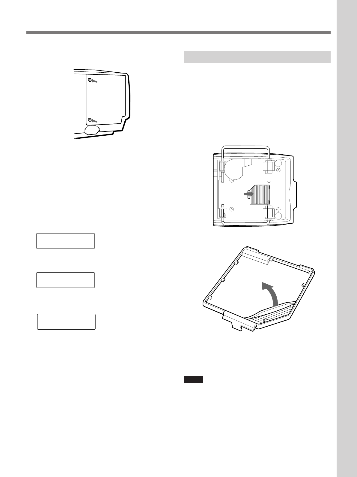
Maintenance
TIMER RESET?
LAMP: 1
TIMER RESET?
LAMP: ALL
TIMER RESET??
LAMP: ALL
4 Replace the lamp cover and push to tighten the two
screws to fix the cover.
To reset the use time of the lamps in the
message display window
1 Plug in the power cord and set the projector to
standby mode.
2 Press the LIGHT, B, b and ENTER keys on the
control panel in sequence. Press each key within 5
seconds.
Cleaning the Air Filter
The air filter should be cleaned in every 100 hours.
When it becomes difficult to remove the dust from the
filter, replace the filter with a new one.
1 Turn off the power of the projector and unplug the
power cord.
2 Remove the air filter cover on the bottom of the
projector.
3 Press the V or v key to display ALL.
4 Press the ENTER key.
5 Press the ENTER key again to reset the time.
The reset mode will be automatically cancelled.
3 Remove the air filter.
4 Remove the dust from the filter with a vacuum
cleaner.
5 Attach the air filter and replace the cover.
Notes
•If the air filter is excessively dirty, wash it with mild
detergent solution and dry it in a shaded place.
•Be sure to attach the air filter cover firmly; the power
will not be turned on if it is not closed securely.
49 (GB)
Page 50
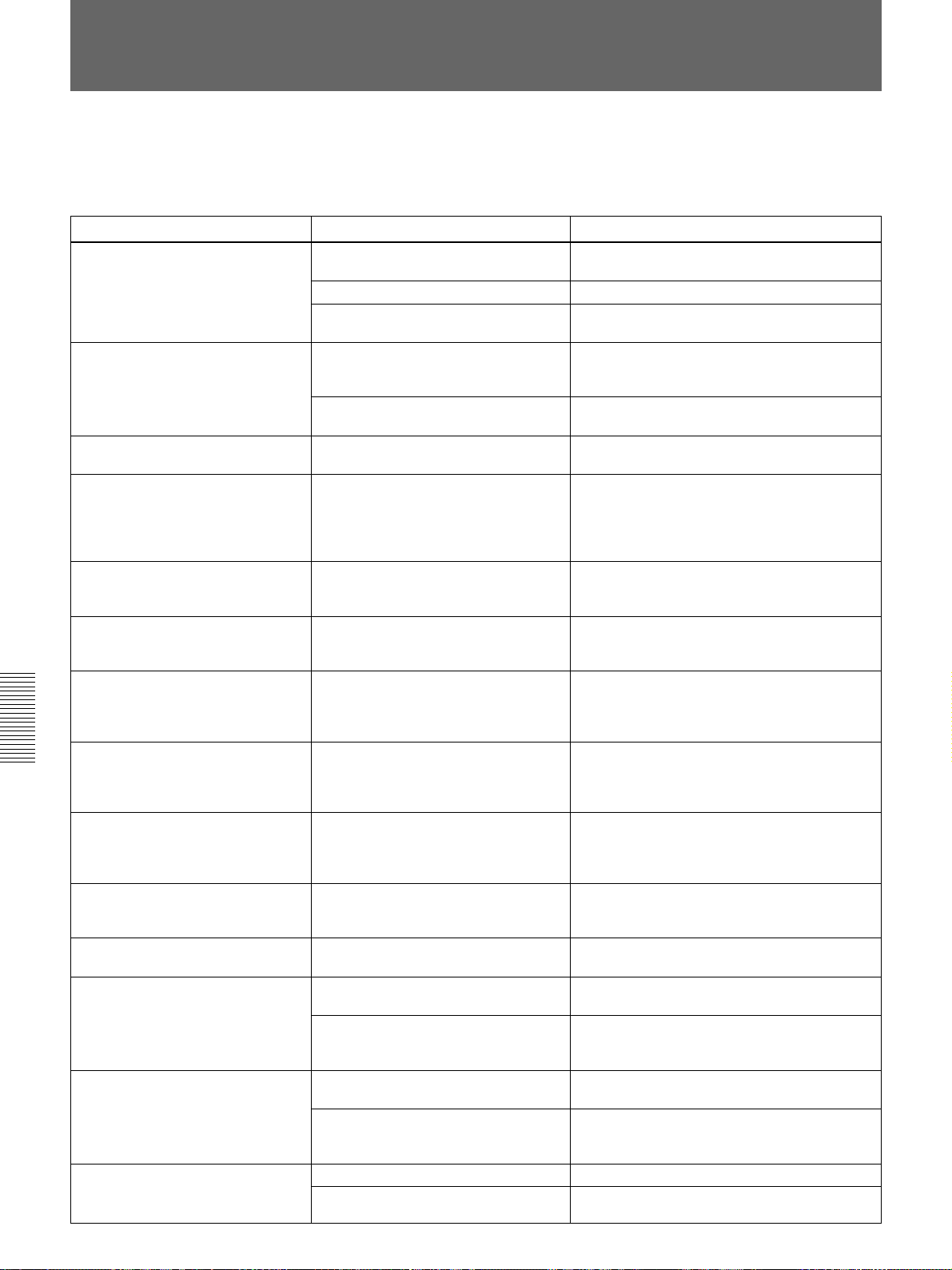
Troubleshooting
If the projector appears to be operating erratically, try to diagnose and
correct the problem, using the following guide. If the problem still persists,
consult with qualified Sony personnel.
Symptom
The power is not turned on.
No picture and no sound.
No picture or no sound.
The picture is noisy.
When inputting sound through the
INPUT A/B/C connector, sound
comes through one channel only.
The picture from INPUT A/B/C
connector is colored strange.
“Please check INPUT-A in SIGNAL
SELECT” appears in spite of
inputting the correct signal from
INPUT A.
“Please check INPUT-B in SIGNAL
SELECT” appears in spite of
inputting the correct signal from
INPUT B.
“Please check INPUT-C in SIGNAL
SELECT” appears in spite of
inputting the correct signal from
INPUT C.
“NO INPUT” appears when 15k RGB
or component signal is input.
On-screen displays do not appear.
Color balance is not correct.
The picture is too dark.
The picture is not clear.
50 (GB)
Cause
The power has been turned off and on
with the ON key at a short interval.
The lamp cover is detached.
The air filter cover is detached.
Cable is disconnected.
Input selection is not correct.
Either the picture or the sound is cut
off.
Noise may appear on the background
depending on the combination of the
numbers of dot input from the
connector and numbers of pixel on the
LCD panel.
Monaural sound is being input through
the INPUT A/B/C connector.
Setting for INPUT-A, INPUT-B or
INPUT-C in the SIGNAL SELECT
menu is incorrect.
Setting for INPUT-A in the SIGNAL
SELECT menu is incorrect.
Setting for INPUT-B in the SIGNAL
SELECT menu is incorrect.
Setting for INPUT-C in the SIGNAL
SELECT menu is incorrect.
The sync signal is incorrect.
STATUS in the SET SETTING menu is
set to OFF.
Picture has not been adjusted
properly.
The color system of the input signal is
not set correctly.
The lamp is nearing the end of its life.
Contrast or brightness has not been
adjusted properly.
The picture is out of focus.
Moisture condensation has occurred
on the lens.
Remedy
Wait for about one minute before turning on
the power
Attach the lamp cover securely.
Attach the air filter cover securely
49 (GB))
Check that the proper connections have been
made
(GB))
Select the input source correctly in the
SIGNAL SELECT menu
Press the MUTING key to cancel the muting
function
Change the desktop pattern on the connected
computer.
Input stereo sound.
Set INPUT-A, INPUT-B or INPUT-C in the
SIGNAL SELECT menu correctly according to
the input signal
Set INPUT-A in the SIGNAL SELECT menu
correctly according to the input signal
page 32 (GB))
Set INPUT-B in the SIGNAL SELECT menu
correctly according to the input signal
page 32 (GB))
Set INPUT-C in the SIGNAL SELECT menu
correctly according to the input signal
page 32 (GB))
Input the correct sync singal (composite sync
or sync on G singal (sync on Y for component
singal)).
Set STATUS in the SET SETTING menu to
ON
Adjust the picture
Set COLOR SYS in the PICTURE CTRL menu
to match the color system of the input
(see page 26 (GB))
Replace the lamp with a new one
48 (GB))
Adjust CONTRAST or BRIGHT in the
PICTURE CTRL menu properly
(GB))
Adjust the focus
Leave the projector for about two hours with
the power on
(see page 10 (GB))
.
(see page
.
(see pages 20 (GB), 42 (GB) and 43
.
(see page 32 (GB))
(see page 10 (GB))
(see page 32 (GB))
.
.
.
(see page 30 (GB))
.
.
.
(see pages 25 and 26 (GB))
.
(see page
.
(see page 25
.
(see page 22 (GB))
(see page 18 (GB))
.
.
.
(see
(see
(see
signal
.
Page 51
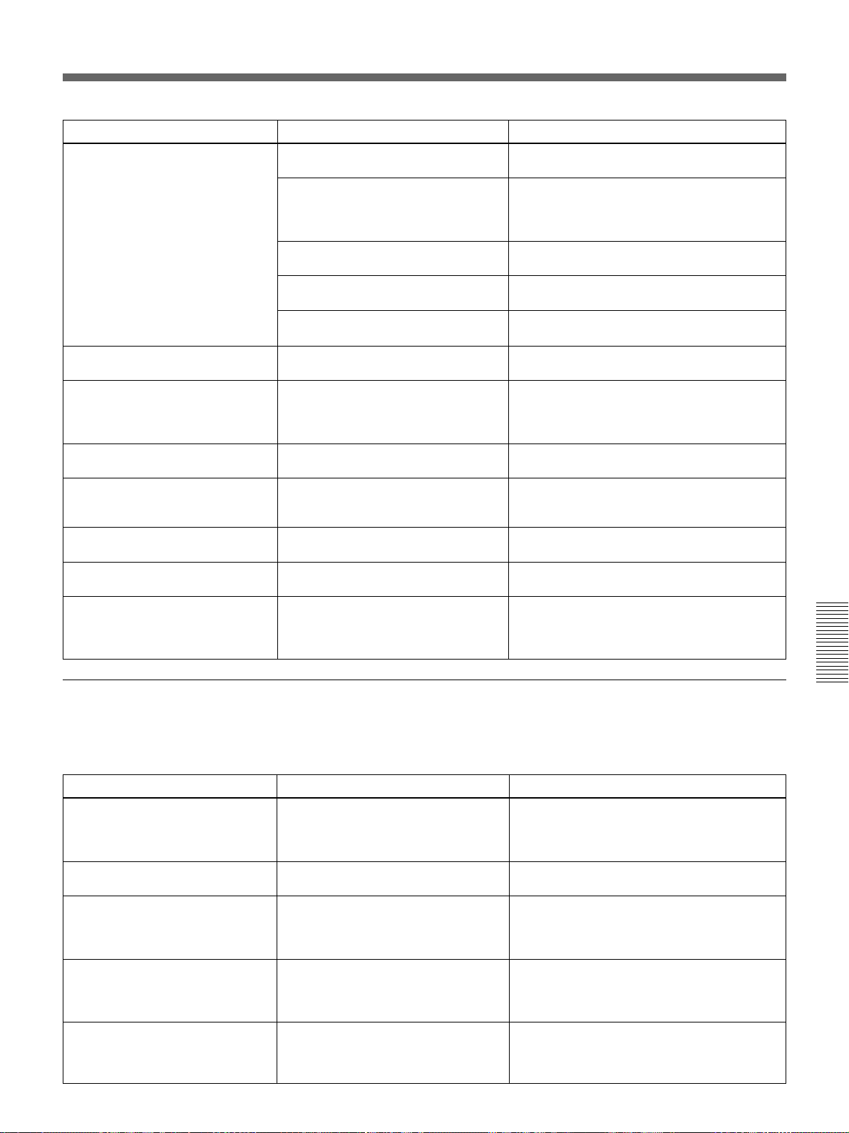
Symptom
The Remote Commander does not
work.
The wireless Remote Commander
does not function.
INPUT A cannot be selected.
The COVER FAIL indicator lights.
The LAMP FAIL indicator lights.
The FAN indicator lights.
Cause
The batteries are exhausted.
The remote commander cable is
connected to the Remote Commander
although you are using it as a wireless
Remote Commander.
The fluorescent lamp influences on the
Remote Commander detector.
You have selected a wrong index
number.
You have set the index number to “00”.
The SIRCS RECEIVER setting is not
correct.
The switcher is not connected, but is
recognized to be connected.
The lamp cover or air filter cover is
detached.
The lamp with the same number of the
indicator has reached the end of its
life.
The fan is broken.
Remedy
Replace the batteries with new ones
page 17 (GB))
Disconnect the remote control cable.
Change the setting of SIRCS RECEIVER in
the SET SETTING menu
Select the correct index number
(GB) and 45 (GB))
Select the correct index number
(GB))
.
Change the setting of SIRCS RECEIVER in
the SET SETTING menu
If the PJ COM connector is connected to
something other than the terminator, remove it
then press the SYS SET key, or LIGHT and
RESET keys on the control panel.
Attach the lamp cover or air filter cover
securely
Replace the lamp
Consult with qualified Sony personnel.
.
(see page 31 (GB))
.
(see page 31 (GB))
(see pages 48 (GB) and 49 (GB))
(see page 48 (GB))
(see
(see pages 31
(see page 45
.
.
.
.
The HIGH TEMP indicator lights.
When you press the ZOOM, SHIFT
or FOCUS key, “LENS CONTROL
is locked! Do you wish to unlock ?”
appears.
Caution messages
Message
High Temperature!
Power off in 1 min.
Frequency is out of range!
Please check INPUT-A in SIGNAL
SELECT.
Please check INPUT-B in SIGNAL
SELECT.
Please check INPUT-C in SIGNAL
SELECT.
The internal temperature is unusually
high.
The lens control function is locked.
Check to see if nothing is blocking the
ventilation holes.
Consult with qualified Sony service personnel.
Use the list below to check the meaning of the messages displayed on the
screen.
Meaning
Internal temperature becomes too high.
The frequency of the input signal is out
of the acceptable range.
You have input the RGB signal from
the computer when INPUT-A in the
SIGNAL SELECT menu is set to
COMPONENT or YP
You have input the RGB signal from
the computer when INPUT-B in the
SIGNAL SELECT menu is set to
COMPONENT or YP
You have input the RGB signal from
the computer when INPUT-C in the
SIGNAL SELECT menu is set to
COMPONENT or YP
BPR.
BPR.
BPR.
Turn off the power. (If not, the power is
automatically turned off about one minute
later.) Check to see if nothing is blocking the
ventilation holes.
Input a signal that is within the range of the
frequency.
Set INPUT-A correctly.
Set INPUT-B correctly.
Set INPUT-C correctly.
Remedy
51 (GB)
Page 52

Specifications
Optical characteristics
Projection system 3 LCD panels, 1 lens, 3-primary
color optical shutter system
LCD panel 1.8-inch XGA LCD panel,
2,359,296 pixels
(786,432 pixels × 3)
Lens Option
Light output ANSI lumen
Lamp 120 W UHP × 4
1)
2,400 lm
Electrical characteristics
Color system NTSC3.58/PAL/SECAM/NTSC4.43/
PAL-M system, switched
automatically
Resolution 600 horizontal TV lines (video
input)
1024 × 768 dots (RGB input)
Acceptable computer signal
fH: 15 to 94 kHz
fV: 40 to 120 Hz
Speakers Max. 5 W + 5 W, 90 × 50 mm
5
(3
/8 × 2 inches), stereo
Input/Output
CONTROL S IN/PLUG IN POWER: Stereo
minijack, 5 Vp-p, plug in power,
DC 5 V, maximum output 60 mA
OUT: Stereo minijack, 5 Vp-p
REMOTE RS-232C/422A
D-sub 9-pin (female)
(For details, see “Pin assignment”
on page 54 (GB).)
PJ COM IN: D-sub 9-pin (male)
OUT: D-sub 9-pin (female)
(For details, see “Pin assignment”
on page 54 (GB).)
TRIG Minijack
Power on: DC 12 V, output
impedance: 4.7 kilohms
Power off: 0 V
S VIDEO (priority to Y IN/C IN) (only for VPLX2000U/X2000M)
IN: Mini DIN 4-pin type (male)
Y (luminance): 1 Vp-p ± 2 dB
sync negative, 75 ohms
terminated
C (chrominance): Burst 0.286
Vp-p ± 2 dB (NTSC), 75 ohms
terminated
Burst 0.3 Vp-p ± 2 dB (PAL), 75
ohms terminated
OUT: Loop-through mini DIN 4-
pin type (male)
Loop-through output from the S
VIDEO IN connector
Y IN: BNC type
1 Vp-p ± 2 dB sync negative, 75
ohms terminated
C IN: BNC type
Burst 0.286 Vp-p ± 2 dB
(NTSC), 75 ohms terminated
Burst 0.3 Vp-p ± 2 dB (PAL), 75
ohms terminated
VIDEO (only for VPL-X2000U/X2000M)
IN: BNC type
Composite video, 1 Vp-p ± 2 dB
sync negative, 75 ohms
terminated
OUT: Loop-through BNC type
Loop-through output from the
VIDEO IN connector
AUDIO IN (only for VPL-X2000U/X2000M)
Phono type (stereo)
500 mVrms, impedance more
than 47 kilohms
INPUT A Analog RGB/component: BNC
type
R/R-Y: 0.7 Vp-p ± 2 dB positive,
75 ohms terminated
G: 0.7 Vp-p ± 2 dB positive, 75
ohms terminated
G with sync/Y: 1 Vp-p ± 2 dB sync
negative, 75 ohms
terminated
B/B-Y: 0.7 Vp-p ± 2 dB positive,
75 ohms terminated
SYNC/HD: Composite sync: 0.6–8
Vp-p, high impedance, sync
positive/negative
Horizontal sync: 0.6–8 Vp-p,
high impedance, sync positive/
negative
..........................................................................................................................................................................................................
1) ANSI lumen is a measuring method of American
National Standard IT 7.228.
52 (GB)
Page 53

Others
VD: Vertical sync: 0.6–8 Vp-p,
high impedance, sync positive/
negative
AUDIO IN: Phono type (stereo)
500 m Vrms, impedance more
than 47 kilohms
HDTV (Y/P
B/PR): BNC type
Y: 1 Vp-p ± 2dB positive,
75 ohms
Tri-level sync: ± 0.3 Vp-p
Bi-level sync: 0.3 Vp-p
B/PR: 0.35 Vp-p ± 2dB positive,
P
75 ohms
HDTV (GBR): BNC type
G with sync: 1 Vp-p ± 2 dB,
Storage temperature
–20°C to +60°C (–4°F to +140°F)
Storage humidity 10% to 90%
Supplied Accessories
Remote Commander RM-PJ1001 (1)
Size AA (R6) batteries (3)
Remote commander cable (stereo)
(15 m) (1)
AC power cord (1)
Terminator for the PJ COM
connector (1)
Lens ring (1)
Operating Instructions (1)
Installation Manual for Dealers (1)
Warranty (only for VPL-X2000U)
(1)
75 ohms
Tri-level sync: ± 0.3 Vp-p
Bi-level sync: 0.3 Vp-p
Design and specifications are subject to change
without notice.
B/R: 0.7 Vp-p ± 2dB positive,
75 ohms
Optional accessories
AUDIO OUT (variable out)
Phono type, Max. 1 Vrms
When input is 500 mVrms:
impedance less than 5 kilohms
Safety regulations
VPL-X2000U: UL1950, c-UL
(CSA No. 950), FCC Class A, IC
Class A
VPL-X2000E/X2000M: EN60 950
(TÜV), CE, C-Tick
Projector Lamp LMP-Q2000 (for replacement)
Interface Board
IFB-12A (Analog RGB/component/HDTV/
composite video/S video input with 5BNC type
connectors)
IFB-20 (Analog RGB input with D-sub 9-pin type
connector)
IFB-21 (Analog RGB input/output with HD D-sub
15-pin type connector)
IFB-30 (Digital RGB input with D-sub 9-pin type
connector)
General
IFB-50 (serial digital video input/output with BNC
type connector)
Dimensions 562 × 237 × 649 mm (22 1/4 × 9 3/8
× 25 5/8 inches) (w/h/d)
Mass Approx. 34.5 kg (76 lb 1 oz)
(excluding the optional lens)
Power requirements
VPL-X2000U: AC 100 to 120 V/
220 to 240 V, 50/60 Hz
1)
VPL-X2000E/X2000M: AC 220 to
240 V, 50/60 Hz
Power consumption
Approx. 770 W (Standby mode: 15W
for VPL-X2000U, 20 W for VPLX2000E/X2000M)
Heat dissipation 2628 BTU
IFB-1000 (Composite video input with BNC type
connector/S video input with mini DIN 4-pin
type connector)
IFB-X2000E (Composite video input with phono
jacks/S video input with mini DIN 4-pin type
connector) (only for VPL-X2000E)
Signal Interface Switcher PC-3000
Interface Unit IFU-1271/1271M
SIC Cable
SIC-10/20A/20C/21/22/23/24/24A/25/26/26A/30/
31/M1/M5/M15/M25/M50
9-pin remote cable (for PJ COM)
RCC-5G/10G/30G
Operating temperature
0°C to 40°C (32°F to 104°F)
Operating humidity
35% to 85% (no condensation)
..........................................................................................................................................................................................................
1) UL listed for 120 V operation.
(continued)
53 (GB)
Page 54
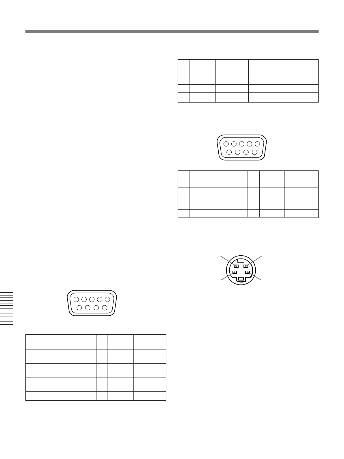
Specifications
12345
6789
Monitor Cable
SMF-400 (HD D-sub 15-pin (female) ˜ 5BNC
(female))
SMF-401 (HD D-sub 15-pin (female) ˜ HD D-
sub 15-pin (female))
Signal Adapter
ADP-10 (D-sub 9-pin ˜ HD D-sub 15-pin (for
SIC Cable))
ADP-20 (Macintosh ˜ VGA)
Remote Commander RM-PJ3000S
Remote Control Receiver RM-PJ10
Projection Lens
Fixed short focus lens VPLL-2009
Fixed short focus lens VPLL-2014
1.3-times zoom standard focus lens VPLL-Z2019
1.6-times zoom long focus lens VPLL-Z2025
1.5-times zoom long focus lens VPLL-Z2039
Fixed long focus lens VPLL-2075
Projector Stand SU-PJ2000 (for stacking)
Projector Suspension Support PSS-2000
Screens
VPS-80FH (80-inch, flat)
VPS-100FH (100-inch, flat)
VPS-120FH (120-inch, flat)
RS-422A
1 GND Ground 6 GND Ground
2
TX
3 RX Receive 8
4 GND Ground 9 GND Ground
5NC
Transmit 7 TX Transmit
RX
Receive
PJ COM connector (D-sub 9-pin, female)
1 GND Ground 6 GND Ground
2 BUSY Busy 7 Busy
3 TX/RX 8
4 GND Ground 9 GND Ground
5NC
Tramsmit/
Receive
BUSY
TX/RX
Tramsmit/
Receive
Some of the items may not be available in some areas.
For details, please consult your nearest Sony office.
Pin assignment
RS-232C/422A connector (D-sub 9-pin, female)
12345
6789
RS-232C
1 NC 6 DSR* Data Set
2
RD
3TD
4 DTR*
5 GND Ground
Receive Data
Transmit Data
Data Terminal
Ready
7 RTS** Request
8
CTS
9NC
Ready
to Send
** Clear to
Send
S VIDEO connector (mini DIN 4-pin)
Chrominance
GND
Luminance
GND
* Circuit between pins 4 and 6 is short-circuited in the
projector.
** Circuit between pins 7 and 8 is short-circuited in the
projector.
54 (GB)
Page 55
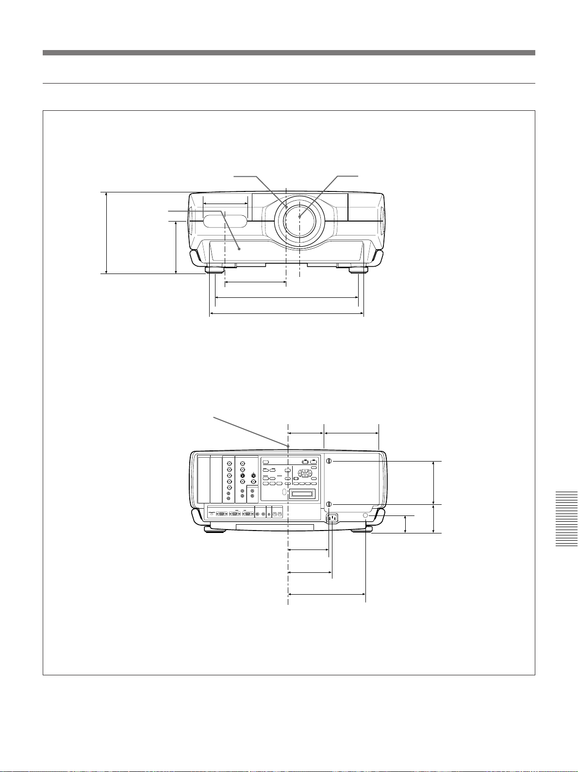
Dimensions
Front
Center of the projector Center of the lens
Rear
/8)
3
237 (9
Ventilation
hole (intake)
/8)
7
149 (5
Center of the projector
INPUT C INPUT B
125 (5)
INPUT A VIDEO
REMOTE CONTROL S TRIG
174.5 (6 7/8)
410.3 (16 1/4)
437.4 (17 1/4)
AUDIO OUT
+
–
DEVICE INDEX
0 0
114.5 (4 5/8)
158 (6 1/4)102 (4 1/8)
/2)
1
139.5
(5
/8)
7
/8)
73
7
47
(1
(2
126 (5)
220.2 (8 3/4)
Unit: mm (inches)
55 (GB)
Page 56
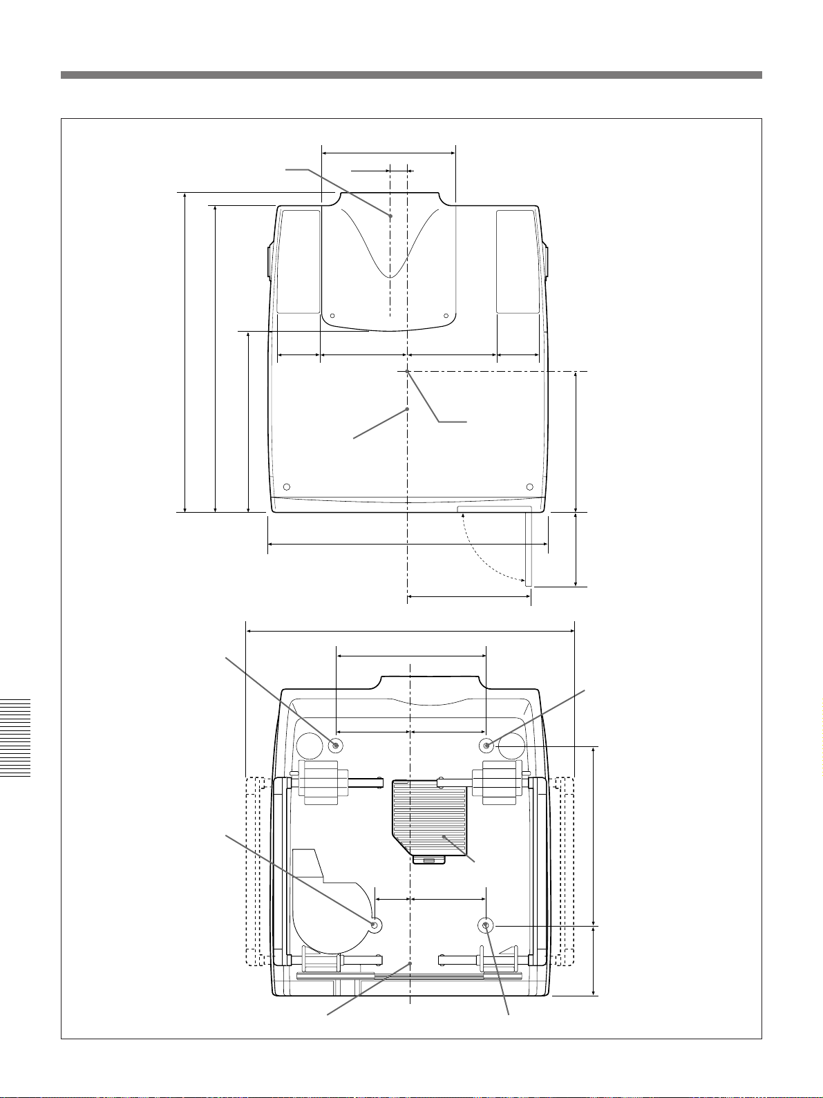
Specifications
Top (excluding the lens)
Center of the lens
/8)
/8)
5
5
649 (25
623.5 (24
)
/8
5
371 (14
86
(3 1/2)
Center of the
projector
274 (10 7/8)
38 (1 1/2)
179 (7 1/8) 179 (7 1/8)
562 (22 1/4)
(3 1/2)
Center of
projection
balance
86
)
/8
5
295 (11
/4)
3
Bottom (excluding the lens)
Hole for attaching the
suspension support
Hole for attaching the
suspension support
251 (10)
665 (26 1/4)
304 (12)
152 (6) 152 (6)
72
(2 7/8)
Ventilation hole
(intake)
152 (6)
145 (5
Hole for attaching the
suspension support
/4)149 (5
1
360 (14
/8)
7
56 (GB)
Center of the projector
Hole for attaching the suspension support
Unit: mm (inches)
Page 57
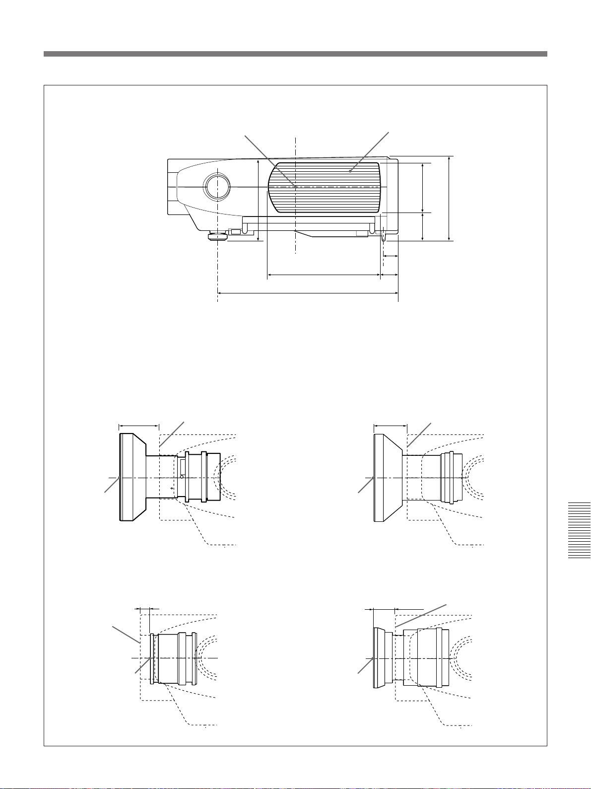
Side (excluding the lens)
Center of projection balance
Dimensions from the front of the
cabinet to the center of the lens
When installing the VPLL-2009 fixed
70.6 (2 7/8)
Front of the cabinet
/8)
1
230 (9
Ventilation hole (left side: exhaust)
/2)
1
139 (5
/8)
1
79
(3
47 (1 7/8)
314 (12 3/8)
509 (20 1/8)
55.7 (2 1/4)
When installing the VPLL-2014 fixed
short focus lens
63 (2 1/2)
Front of the cabinet
/8)
3
237 (9
Center of the
lens
When installing the VPLL-Z2019 1.3-times
zoom standard focus lens
– 25.4 (– 1)
Front of the cabinet
Center of the lens
Center of the
lens
When installing the VPLL-Z2025 1.6-times
zoom long focus lens
42.4 (1 11/16)
Center of the lens
Front of the cabinet
Unit: mm (inches)
57 (GB)
Page 58
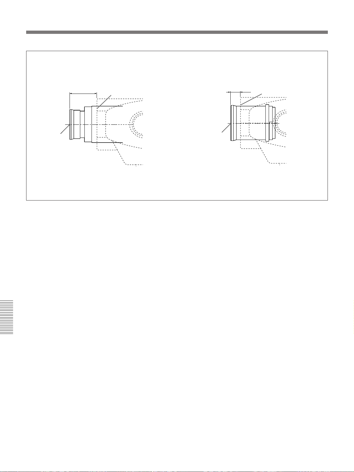
Specifications
When installing the VPLL-Z2039 1.5-times
zoom long focus lens
84.5 (3 3/8)
Center of the
lens
Front of the cabinet
When installing the VPLL-2075 fixed long focus
lens
29.5 (1 3/16)
Center of the lens
Front of the cabinet
Unit: mm (inches)
58 (GB)
Page 59

Index
A
Adjusters 9 (GB)
Adjusting
picture 25 (GB)
picture size/shift 27 (GB)
zoom 22 (GB)
Air filter 49 (GB)
ASPECT 28 (GB)
AUDIO MUTING 23 (GB)
B
Battery
Installation 17 (GB)
notes 17 (GB)
BLANKING 28 (GB)
BNC connector 42 (GB)
BRIGHT 25 (GB)
C
Carrying handles 9 (GB)
Caution messages 51 (GB)
COLOR 25 (GB)
COLOR SYS (System) 26 (GB)
COLOR TEMP 26 (GB)
Connections
active speakers 20 (GB)
BNC Connector 42 (GB)
computer 20 (GB)
15k RGB/component equipment
42 (GB)
Remote Commander 17 (GB)
switcher 43 (GB)
VCR 20 (GB)
CONTRAST 25 (GB)
Cut off
the picture 23 (GB)
the sound 23 (GB)
D, E
D. (Dynamic) PICTURE 25 (GB)
Device index 31 (GB), 45 (GB)
DOT PHASE 27 (GB)
DRC (Digital Reality Creation) 26 (GB)
F
G
GAMMA MODE 26 (GB)
Group index 31 (GB), 45 (GB)
H
Handle lever 9 (GB)
H FILTER 28 (GB)
HUE 25 (GB)
I, J, K
INPUT-A 32 (GB)
INPUT-B 32 (GB)
INPUT-C 32 (GB)
INPUT MEMORY No. 29 (GB)
INPUT SETTING menu 27 (GB)
Input signal selection 21 (GB)
Installation examples
on a ceiling 38 (GB)
on a floor 19 (GB), 34 (GB)
L
Lamp replacement 48 (GB)
LANGUAGE 30 (GB)
Location and function of controls
control panel 10 (GB)
front 8 (GB)
rear 12 (GB)
Remote Commander 14 (GB)
M, N
Menu
Clearing the menu display 24 (GB)
INPUT SETTING menu 27 (GB)
PICTURE CTRL menu 25 (GB)
SET SETTING menu 30 (GB)
SIGNAL SELECT menu 32 (GB)
Using the menu 24 (GB)
Moisture condensation 18 (GB)
O
On-screen display 30 (GB)
On-screen messages 51 (GB)
Optional accessories 53 (GB)
PIC MUTING 23 (GB)
PICTURE CTRL menu 25 (GB)
PICTURE SHIFT 23 (GB)
Pin assignment 54 (GB)
PJ COM connector 43 (GB)
Power
turn on 21 (GB)
turn off 23 (GB)
POWER SAVING 31 (GB)
Precautions 4 (GB)
Precautions on installation 18 (GB)
Projecting 21 (GB)
PSS-2000 Projector Suspension Support
38 (GB)
R
Remote Commander
battery installation 17 (GB)
connecting to the projector 17 (GB)
location and function of controls
14 (GB)
notes 17 (GB)
Remote control detector
front 8 (GB)
rear 11 (GB)
Reset
resetting the item 24 (GB)
RS-232C/422A connector 13 (GB)
S
SCAN CONV 27 (GB)
Screen size 35 (GB) – 41 (GB)
SET SETTING menu 30 (GB)
SHARP 25 (GB)
SHIFT 27 (GB)
SIGNAL SELECT menu 32 (GB)
SIRCS RECEIVER 31 (GB)
SIZE 27 (GB)
SPEAKER 30 (GB)
Specifications 52 (GB)
STATUS 30 (GB)
Supplied accessories 53 (GB)
T, U, V, W, X, Y
Troubleshooting 50 (GB)
fH (Horizontal frequency) 29 (GB)
FOCUS 22 (GB)
fV (Vertical frequency) 29 (GB)
P, Q
PC-3000 Signal Interface Switcher
43 (GB)
Z
ZOOM 22 (GB)
59 (GB)
 Loading...