

Page 1
Video Projector
4-125-589-11 (1)
VPL-VW70
© 2008 Sony Corporation
Operating Instructions
Mode d’emploi
GB
FR
Page 2
WARNING
To reduce the risk of fire or electric
shock, do not expose this apparatus
to rain or moisture.
To avoid electrical shock, do not
open the cabinet. Refer servicing to
qualified personnel only.
THIS APPARATUS MUST BE
EARTHED.
This symbol is intended to
alert the user to the presence
of uninsulated “dangerous
voltage” within the
product’s enclosure that may
be of sufficient magnitude to
constitute a risk of electric
shock to persons.
This symbol is intended to
alert the user to the presence
of important operating and
maintenance (servicing)
instructions in the literature
accompanying the
appliance.
For customers in the USA
If you have any questions about this product,
you may call:
Sony Customer Information Service Center
1-800-222-7669 or http://www.sony.com/
The number below is for FCC related
matters only.
Declaration of Conformity
Trade Name: SONY
Model No.: VPL-VW70
Responsible Party: Sony Electronics Inc.
Address: 16530 Via Esprillo, San Diego, CA
92127 U.S.A.
Telephone Number: 858-942-2230
This device complies with Part 15 of the
FCC Rules. Operation is subject to the
following two conditions: (1) This device
may not cause harmful interference, and (2)
this device must accept any interference
received, including interference that may
cause undesired operation.
This equipment has been tested and found to
comply with the limits for a Class B digital
device, pursuant to Part 15 of the FCC
Rules. These limits are designed to provide
reasonable protection against harmful
interference in a residential installation. This
equipment generates, uses, and can radiate
radio frequency energy and, if not installed
and used in accordance with the instructions,
may cause harmful interference to radio
communications. However, there is no
guarantee that interference will not occur in
a particular installation. If this equipment
does cause harmful interference to radio or
television reception, which can be
determined by turning the equipment off and
on, the user is encouraged to try to correct
the interference by one or more of the
following measures:
- Reorient or relocate the receiving antenna.
- Increase the separation between the
equipment and receiver.
- Connect the equipment into an outlet on a
circuit different from that to which the
receiver is connected.
- Consult the dealer or an experienced radio/
TV technician for help.
You are cautioned that any changes or
modifications not expressly approved in this
manual could void your authority to operate
this equipment.
All interface cables used to connect
peripherals must be shielded in order to
comply with the limits for a digital device
pursuant to Subpart B of Part 15 of FCC
Rules.
GB
2
Page 3
Disposal of Used Lamp
This projector’s lamp contains mercury and
should be disposed of properly. Consult your
local authorities regarding safe disposal.
The material contained in this lamp are
similar to those of a fluorescent lamp, so you
should dispose of it in the same way.
For customers in the United States
Lamp in this product contains mercury.
Disposal of these materials may be regulated
due to environmental considerations. For
disposal or recycling information, please
contact your local authorities or the
Electronic Industries Alliance
(www.eiae.org).
For customers in Canada
This Class B digital apparatus complies with
Canadian ICES-003.
The socket-outlet should be installed near
the equipment and be easily accessible.
Trademark Information
HDMI, the HDMI logo and High-Definition
Multimedia Interface are trademarks or
registered trademarks of HDMI Licensing
LLC.
“Blu-ray Disc” is a trademark.
CAUTION
RISK OF EXPLOSION IF BATTERY IS
REPLACED BY AN INCORRECT
TYPE.
DISPOSED OF USED BATTERIES
ACCORDING TO THE LOCAL RULES.
Installing batteries
Two R6 (size AA) batteries are supplied for
Remote Commander.
To avoid risk of explosion, use R6 (size AA)
manganese or alkaline batteries.
GB
GB
3
Page 4

Table of Contents
Precautions .........................................6
Location of Controls
Front/Right Side ................................. 7
Rear/Bottom ....................................... 8
Remote Control ..................................9
Connections and
Preparations
Unpacking ........................................ 10
Step 1: Installing the
Projector ........................................... 11
Before Setting Up the
Projector ..................................... 11
Positioning the Projector and a
Screen ......................................... 13
Step 2: Connecting the Projector .....17
Connecting to a VCR ................. 17
Connecting to a Computer ......... 20
Step 3: Adjusting the Picture
Position ............................................ 21
Step 4: Selecting the Menu
Language .......................................... 27
Projecting
Projecting the Picture on the
Screen ...............................................29
Turning Off the Power ................30
Operating the BRAVIA Sync
Compatible Equipment with the
Remote Control of the Projector ......31
Selecting the Wide Screen Mode .....33
Selecting the Picture Viewing
Mode ................................................36
Adjusting the Picture Quality ...........37
Selecting to Directly Adjust the
Desired Menu Item .....................37
Selecting Desired Adjust Menu
Items in the Order .......................38
Adjusting the Picture Using Real
Color Processing ...............................39
Using the Supplied Software to
Adjust the Picture Quality
(ImageDirector3) ..............................40
Using the Menus
Operation through the Menus ...........41
Picture Menu ....................................45
Advanced Picture Menu ...................49
Screen Menu .....................................50
Setup Menu .......................................52
Function Menu .................................54
Installation Menu ..............................56
Information Menu .............................59
About the Preset Memory No. ....59
GB
4
Page 5

Others
About the Control for HDMI ...........60
About the x.v.Color ..........................61
Troubleshooting ...............................62
Warning Indicators .....................65
Message Lists .............................66
Replacing the Lamp and the Air Filter
and Cleaning the Ventilation Holes
(intake) .............................................68
Cleaning the Air Filter .....................71
Cleaning and the Screen of the
Projector ...........................................71
Specifications ...................................73
Preset Signals .............................75
Input Signals and Adjustable/
Setting Items ...............................78
Ceiling Installation ...........................80
Index ...............................................84
GB
5
Page 6

Precautions
On safety
• Check that the operating voltage of your
unit is identical with the voltage of your
local power supply.
• Should any liquid or solid object fall into
the cabinet, unplug the unit and have it
checked by qualified personnel before
operating it further.
• Unplug the unit from the wall outlet if it is
not to be used for several days.
• To disconnect the cord, pull it out by the
plug. Never pull the cord itself.
• The wall outlet should be near the unit and
easily accessible.
• The unit is not disconnected to the AC
power source (mains) as long as it is
connected to the wall outlet, even if the
unit itself has been turned off.
• Do not look into the lens while the lamp is
on.
• Do not place your hand or objects near the
ventilation holes. The air coming out is
hot.
On preventing internal heat buildup
After you turn off the power with the ?/1
(on/standby) switch, do not disconnect the
unit from the wall outlet while the cooling
fan is still running.
Caution
The projector is equipped with ventilation
holes (intake) and ventilation holes
(exhaust). Do not block or place anything
near these holes, or internal heat build-up
may occur, causing picture degradation or
damage to the projector.
On repacking
Save the original shipping carton and
packing material; they will come in handy if
you ever have to ship your unit. For
maximum protection, repack your unit as it
was originally packed at the factory.
GB
6
Page 7
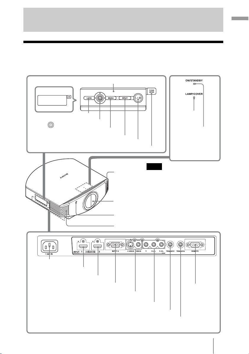
Location of Controls
Front/Right Side
You can use the buttons on the control panel with the same names as those on the remote
control to operate the projector.
Press the button and open
the cover.
Control panel
Location of Controls
M/m/</, (arrow)/
LENS button
(enter) button (1 page 41)
MENU button (1 page 41)
INPUT button (1 page 29)
?/1 (on/standby) switch (1 page 22)
Open button
Ventilation
holes (exhaust)
(1 page 12)
Lens protector
Remote control detector (1 page 21)
Ventilation holes (exhaust) (1 page 12)
- AC IN socket
HDMI 1 connector (1 page 18)
HDMI 2 connector (1 page 18)
INPUT A connector (1 page 20)
S VIDEO INPUT connector (mini DIN 4-pin)/VIDEO INPUT
connector (phono type) (1 page 19)
Y PB/CB PR/CR connector (phono type) (1 page 17)
TRIGGER 2 connector
Outputs 12V signal when “Wide Mode” is set to “Anamorphic Zoom”. (1 page 34)
TRIGGER 1 connector
Outputs 12V signal when the projector is on.
LAMP/COVER
indicator
(1 page 65)
ON/STANDBY
indicator
(1 page 21)
Note
While the ON/STANDBY indicator
lights in orange, the power saving
mode is on. (1 page 53)
REMOTE
connector
Connects to a
computer, etc.
for remote
control.
(1 page 40)
GB
7
Page 8
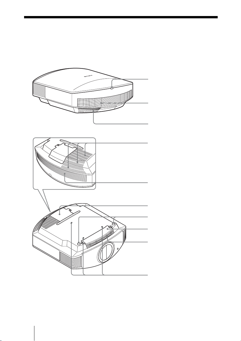
Rear/Bottom
Remote control detector
(1 page 21)
Ventilation holes (intake)
(1 page 12)
Ventilation holes (intake)
(1 page 12)
Ventilation holes (intake)
(1 page 12)
Ventilation holes (intake)
(1 page 12)
GB
Lamp cover (1 page 69)
Adjusters (1 page 26)
Filter holder (1 page 70)
Ventilation holes (intake)
(1 page 12)
Projector suspension
support attaching hole
(1 page 80)
8
Page 9
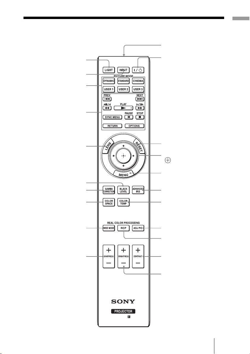
Remote Control
LIGHT button
Illuminates the buttons on
the remote control.
INPUT button
(1 page 29)
PICTURE MODE buttons
(1 page 36)
Buttons to operate
BRAVIA Sync compatible
equipment (1 page 31)
Location of Controls
Infrared transmitter
?/1 (on/standby)
switch (1 page 22)
LENS button
(1 page 21)
BLACK LEVEL button
(1 page 37)
GAMMA CORRECTION
button (1 page 37)
COLOR SPACE button
(1 page 37)
WIDE MODE button
(1 page 33)
SHARPNESS +/– button
(1 page 46)
RESET button
(1 page 41)
M/m/</, (arrow)/
(enter) buttons
(1 page 41)
MENU button
(1 page 41)
ADVANCED IRIS button
(1 page 37)
COLOR TEMP button
(1 page 37)
ADJ PIC (Adjust Picture)
button (1 page 38)
RCP (Real Color
Processing) button
(1 page 39)
CONTRAST +/– button
(1 page 46)
BRIGHTNESS +/– button
(1 page 46)
GB
9
Page 10
Connections and Preparations
This section describes how to install the projector and screen, how to connect the
equipment from which you want to project the picture, etc.
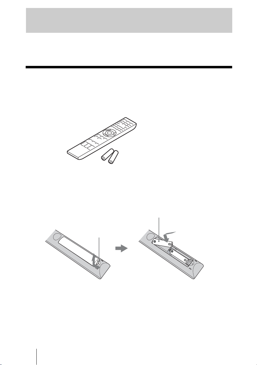
Unpacking
Check the carton to make sure it contains the following items:
• Remote control (1) and
Size AA (R6) manganese batteries (2)
• AC power cord (1)
• ImageDirector3 CD-ROM (1)
• Operating Instructions (this manual)
Inserting the batteries into the remote control
Insert the batteries E side first as shown in the illustration.
Inserting them forcibly or with the polarities reversed may
cause a short circuit and may generate heat.
Push and slide
to open.
Caution about handling the remote control
• Handle the remote control with care. Do not drop or step on it, or spill liquid of any kind
onto it.
• Do not place the remote control in a location near a heat source, a place subject to direct
sunlight, or a damp room.
GB
10
Page 11
Step 1: Installing the Projector
The projector displays pictures output from
a VCR or other device.
The lens shift allows you to have broader
options for placing the projector and
viewing pictures easily.
Before Setting Up the
Projector
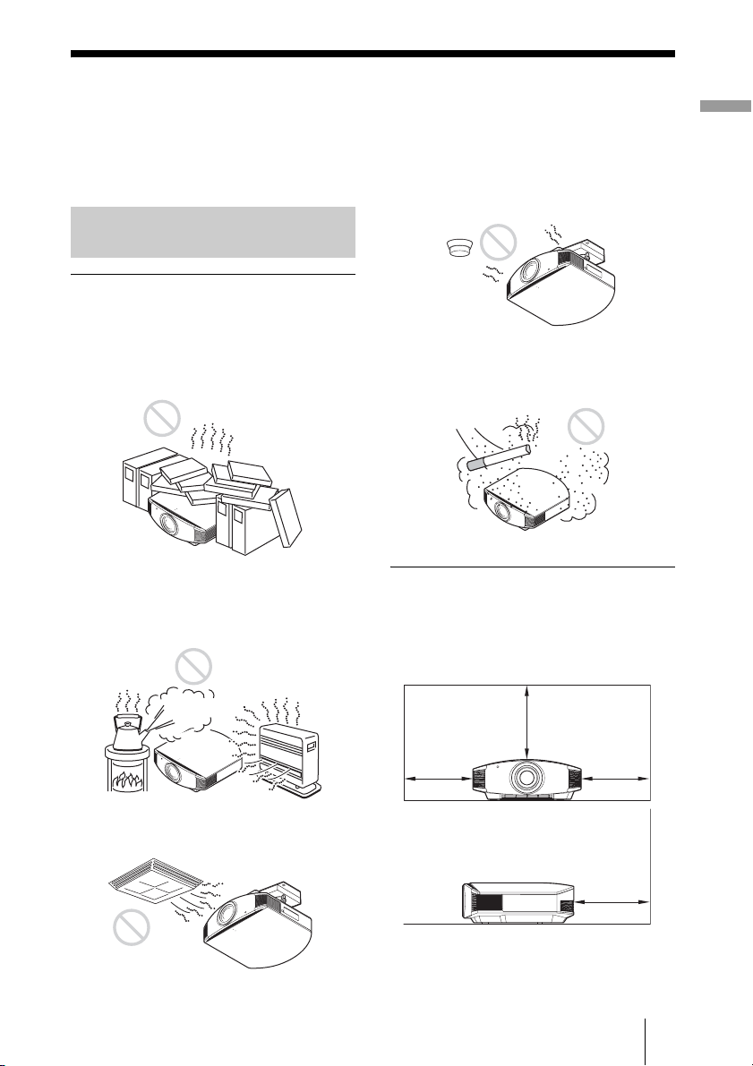
Unsuitable installation
Do not place the projector in the following
situations, which may cause malfunction
or damage to the projector.
Poorly ventilated location
Leave space of more than 30 cm (11 7/8 inches)
around the unit.
Hot and humid
Installing the projector in such a location
may cause a malfunction of the unit due to
moisture condensation or rise in
temperature.
Near a heat or smoke sensor
Malfunction of the sensor may occur.
Very dusty and extremely smoky
locations
Install in a location away from walls
To maintain the performance and
reliability of the projector, allow at
least 30 cm (11 7/8 inches) between
the projector and walls.
Connections and Preparations
Locations subject to direct cool or
warm air from an air-conditioner
30 cm
(11 7/8inches)
30 cm
(11
7
/8inches)
(11
30 cm
(11 7/8inches)
30 cm
7
/8inches)
11
GB
Page 12
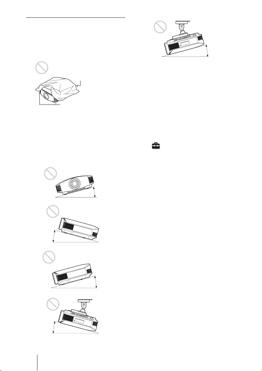
Improper use
Do not do any of the following while using
the projector.
Blocking the ventilation holes (intake
or exhaust)
Ventilation holes
(intake)
Ventilation holes
(exhaust)
Tip
For details on the location of the ventilation
holes (intake or exhaust), see “Location of
Controls” on page 7.
Tilting front/rear and left/right
15° or more
15° or more
Avoid using the projector tilted at an angle
of more than 15 degrees.
Do not install the projector anywhere other
than on a level surface or on the ceiling.
Installing the projector in such a location
may result in uneven color uniformity or
reduce the reliability of the effects of the
lamp.
When installing the unit at high
altitudes
When using the projector at an altitude of
1,500 m or higher, set “Cooling Setting” in the
Setup menu to “High” (1 page 52).
Failing to set this mode when using the
projector at high altitudes could have adverse
effects, such as reducing the reliability of
certain components.
15° or more
15° or more
GB
12
15° or more
Page 13
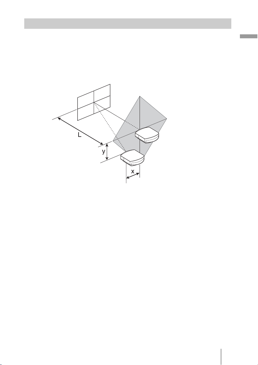
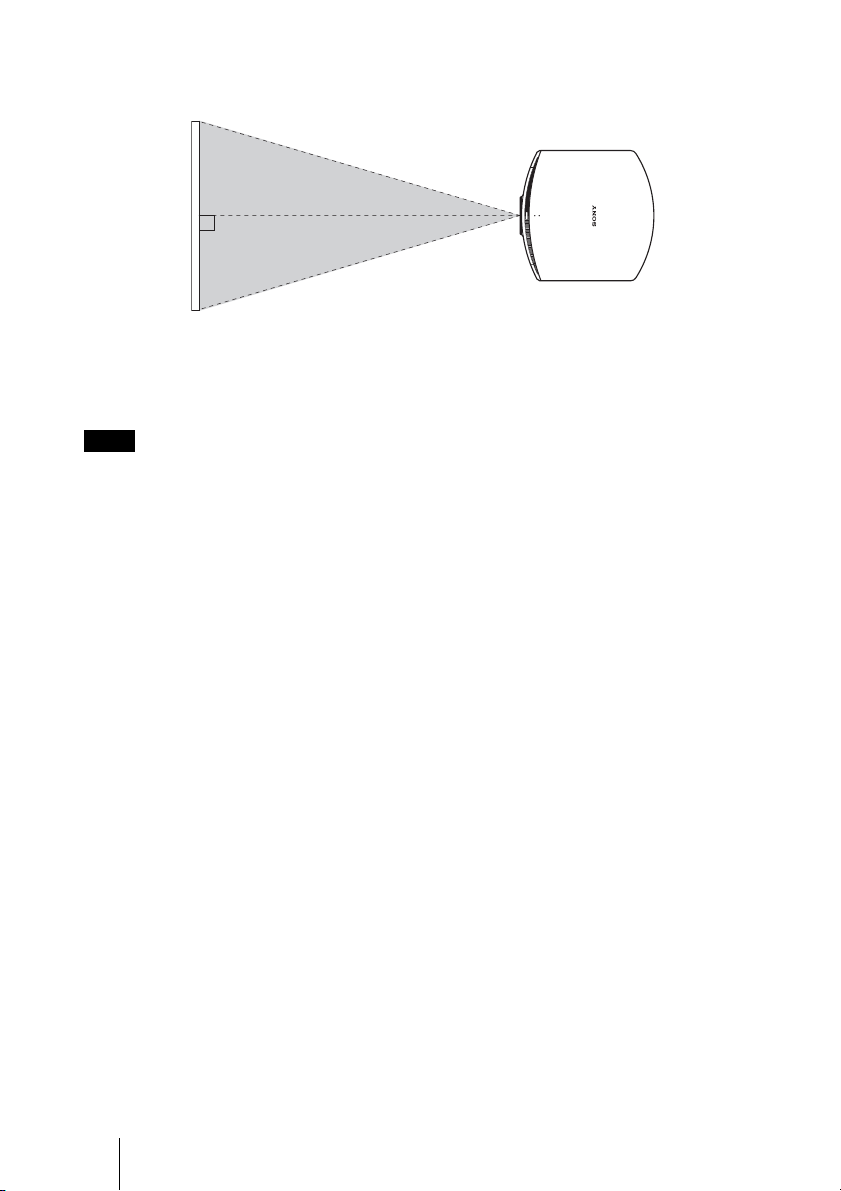
Positioning the Projector and a Screen
The installation distance between the projector and a screen varies depending on the size
of the screen or whether or not you use the lens shift features.
1 Determine the installation position of the projector and screen.
You can obtain a good quality picture if you position the projector so that the center
of the lens is within the area indicated in gray in the illustration.
Use the values L, x and y in the table on page 14 or 15 as a guide.
Screen
*
**
* Installation position not using lens shift (x = 0, y = 0)
** Example of installation position using lens shift (x, y)
Connections and Preparations
L: Distance between the screen and the front end of the projector’s lens.
x: Horizontal distance between the center of the screen and the center of the
projector’s lens.
y: Vertical distance between the center of the screen and the center of the projector’s
lens.
For installation of the projector on a ceiling, see “Ceiling Installation.” (1 page 80)
For details on the lens shift feature, see “Step 3: Adjusting the Picture Position.”
(1 page 21)
13
GB
Page 14
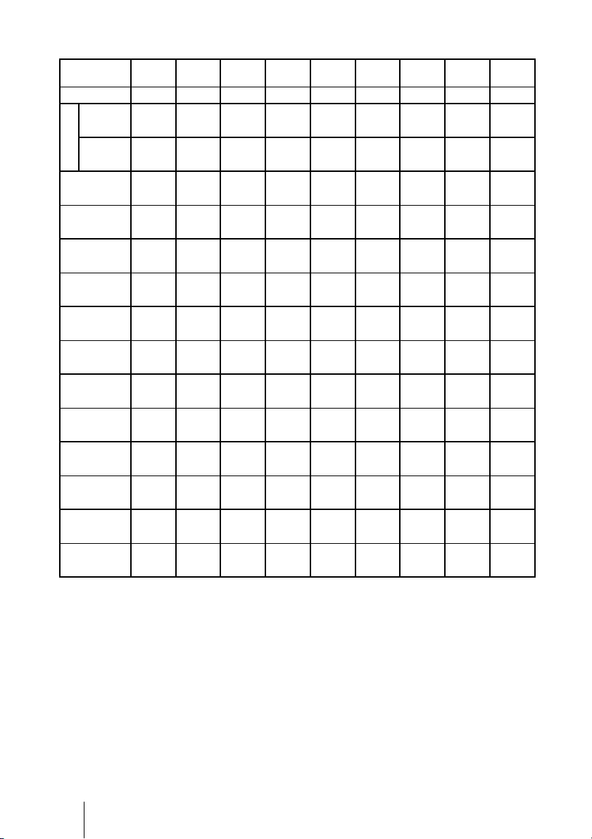
When using the 16:9 aspect ratio screen size
Screen Size
SS (inches)
(mm) 1016 1524 2032 2540 3048 3810 5080 6350 7620
minimum 1201 1825 2448 3072 3695 4631 6189 7748 9307
L
maximum 1840 2782 3723 4664 5605 7017 9371 11724 14077
x 000000000
y 324 486 648 809 971 1214 1619 2024 2428
x 44 66 89 111 133 166 221 277 332
y 259 389 518 648 777 971 1295 1619 1943
x 89 133 177 221 266 332 443 553 664
y 194 291 389 486 583 728 971 1214 1457
x 133 199 266 332 398 498 664 830 996
y 130 194 259 324 389 486 648 809 971
x 177 266 354 443 531 664 886 1107 1328
y 65 97 130 162 194 243 324 405 486
x 221 332 443 553 664 830 1107 1384 1660
y 000000000
To calculate the installation positions
L (minimum) = 31.1781 (1
L (maximum) = 47.0644 (1
y = –1.463 × x (mm or inch) + 8.0942 (
40 60 80 100 120 150 200 250 300
(47 3/8) (71 7/8) (96 1/2) (121) (145 1/2) (182 3/8) (243 3/4) (305 1/8) (366 1/2)
(72 1/2) (109 5/8) (146 5/8) (183 5/8) (220 3/4) (276 3/8) (369) (461 5/8) (554 1/4)
(0) (0) (0) (0) (0) (0) (0) (0) (0)
(12 7/8)(19 1/4)(25 5/8)(31 7/8)(38 1/4)(47 7/8)(63 3/4)(79 3/4)(95 5/8)
(1 3/4)(2 5/8)(3 5/8)(4 3/8)(5 1/4)(6 5/8)(8 3/4) (11) (13 1/8)
(10 1/4)(15 3/8)(20 1/2)(25 5/8)(30 5/8)(38 1/4)(51)(63 3/4)(76 1/2)
(3 5/8)(5 1/4)(7)(8 3/4)(10 1/2)(13 1/8)(17 1/2)(21 7/8)(26 1/4)
(7 3/4)(11 1/2)(15 3/8)(19 1/4)(23)(28 3/4)(38 1/4)(47 7/8)(57 3/8)
(5 1/4)(7 7/8)(10 1/2)(13 1/8)(15 3/4)(19 5/8)(26 1/4)(32 3/4)(39 1/4)
(5 1/8)(7 3/4)(10 1/4)(12 7/8)(15 3/8)(19 1/4)(25 5/8)(31 7/8)(38 1/4)
(7) (10 1/2)(14)(17 1/2)(21)(26 1/4)(35)(43 5/8)(52 3/8)
(2 5/8)(3 7/8)(5 1/8)(6 1/2)(7 3/4)(9 5/8)(12 7/8)(16)(19 1/4)
(8 3/4)(13 1/8)(17 1/2)(21 7/8)(26 1/4)(32 3/4)(43 5/8)(54 1/2)(65 3/8)
(0) (0) (0) (0) (0) (0) (0) (0) (0)
Unit: mm (inches)
7
/32) × SS – 46.1543 (1 13/16)
27
/32) × SS – 42.3308 (1 21/32)
5
/16) × SS
GB
14
Page 15
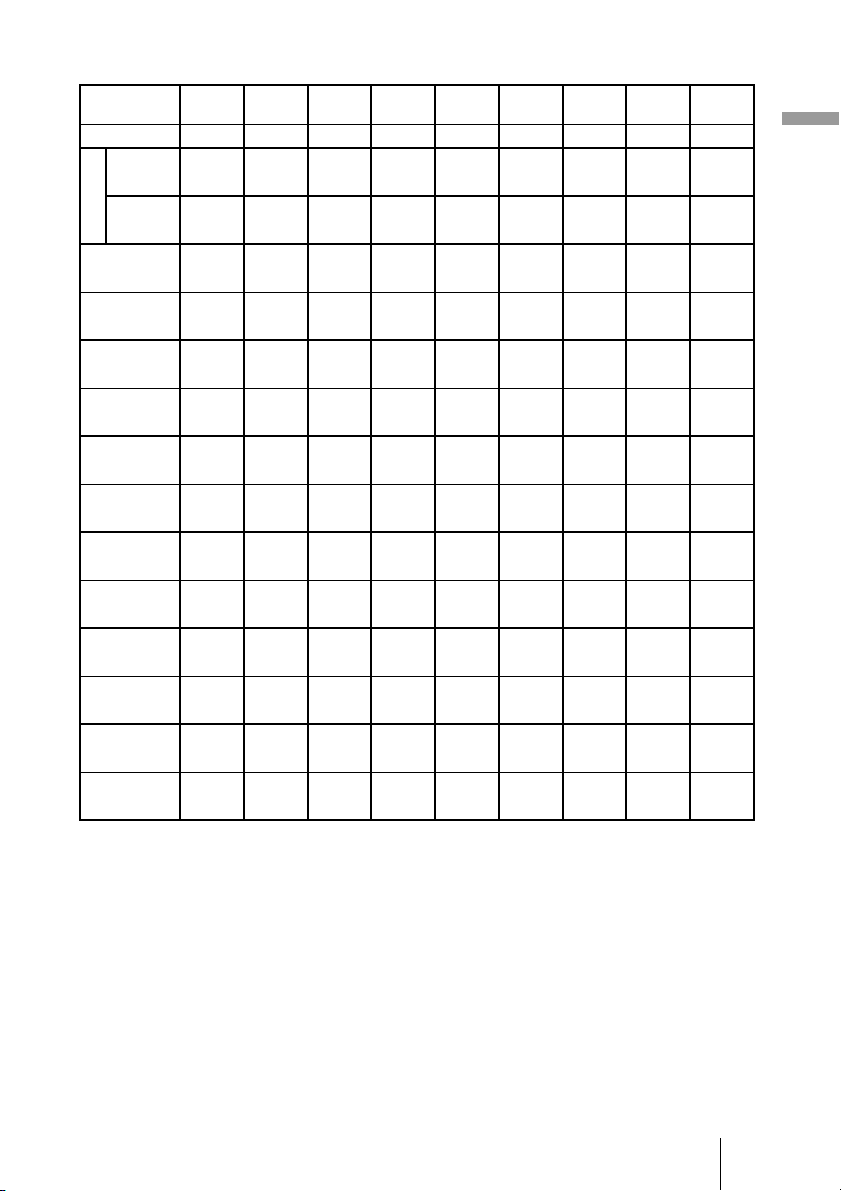
When using the 4:3 aspect ratio screen size
Screen Size
SS (inches)
(mm) 1016 1524 2032 2540 3048 3810 5080 6350 7620
minimum 1480 2243 3006 3770 4533 5677 7585 9493 11401
L
maximum 2262 3414 4566 5718 6870 8598 11478 14357 17237
x 000000000
y 396 594 792 991 1189 1486 1981 2477 2972
x 54 81 108 135 163 203 271 339 406
y 317 475 634 792 951 1189 1585 1981 2377
x 108 163 217 271 325 406 542 677 813
y 238 357 475 594 713 892 1189 1486 1783
x 163 244 325 406 488 610 813 1016 1219
y 158 238 317 396 475 594 792 991 1189
x 217 325 433 542 650 813 1084 1355 1626
y 79 119 158 198 238 297 396 495 594
x 271 406 542 677 813 1016 1355 1693 2032
y 000000000
To calculate the installation positions
L (minimum) = 38.1569 (1
L (maximum) = 57.5992 (2
y = –1.463 × x (mm or inch) + 9.9060 (
40 60 80 100 120 150 200 250 300
(58 3/8)(88 3/8) (118 3/8) (148 1/2) (178 1/2) (223 5/8) (298 5/8) (373 3/4) (448 7/8)
(89 1/8) (134 1/2) (179 7/8) (225 1/8) (270 1/2) (338 5/8) (452) (565 1/4) (678 5/8)
(0) (0) (0) (0) (0) (0) (0) (0) (0)
(15 5/8)(23 1/2) (31 1/4)(39 1/8)(46 7/8)(58 5/8)(78)(97 5/8)
(2 1/4)(3 1/4)(4 3/8)(5 3/8)(6 1/2)(8)(10 3/4)(13 3/8)(16)
(12 1/2)(18 3/4)(25)(31 1/4)(37 1/2)(46 7/8)(62 1/2)(78)(93 5/8)
(4 3/8)(6 1/2)(8 5/8)(10 3/4)(12 7/8)(16)(21 3/8)(26 3/4)(32 1/8)
(9 3/8)(14 1/8) (18 3/4)(23 1/2)(28 1/8)(35 1/8)(46 7/8)(58 5/8)(70 1/4)
(6 1/2)(9 5/8) (12 7/8)(16)(19 1/4)(24 1/8)(32 1/8)(40) (48)
(6 1/4)(9 3/8) (12 1/2)(15 5/8)(18 3/4)(23 1/2)(31 1/4)(39 1/8)(46 7/8)
(8 5/8)(12 7/8) (17 1/8)(21 3/8)(25 5/8)(32 1/8)(42 3/4)(53 3/8)(64 1/8)
(3 1/8)(4 3/4)(6 1/4)(7 7/8)(9 3/8)(11 3/4)(15 5/8)(19 1/2)(23 1/2)
(10 3/4) (16) (21 3/8)(26 3/4)(32 1/8)(40)(53 3/8)(66 3/4)(80)
(0) (0) (0) (0) (0) (0) (0) (0) (0)
Unit: mm (inches)
1
/2) × SS – 46.1543 (1 13/16)
9
/32) × SS – 42.3308 (1 21/32)
3
/8) × SS
Connections and Preparations
(117 1/8)
15
GB
Page 16
2 Position the projector so that the lens is parallel to the screen.
Top view
Screen
3 Project an image on the screen and adjust the picture so that it fits the
screen. (1 page 21)
To project an image, connect video equipment to the projector. (1 page 17)
Note
When using a screen with an uneven surface, stripes pattern may rarely appear on the screen
depending on the distance between the screen and the projector or the zooming magnifications. This
is not a malfunction of the projector.
GB
16
Page 17
Step 2: Connecting the Projector
When making connections, be sure to do the following:
• Turn off all equipment before making any connections.
• Use the proper cables for each connection.
• Insert the cable plugs properly; poor connection at the plugs may cause a malfunction or
poor picture quality. When pulling out a cable, be sure to pull it out from the plug, not
the cable itself.
• Refer to the operating instructions of the connected equipment.
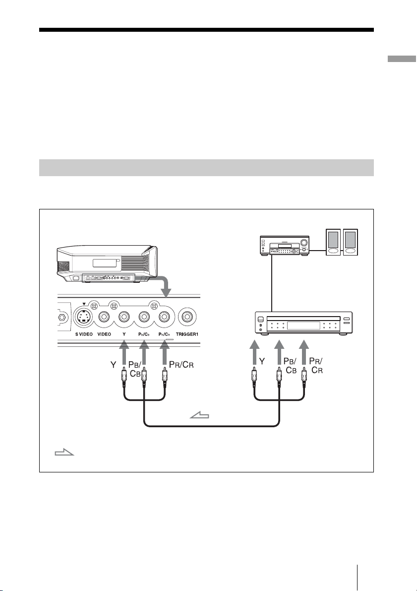
Connecting to a VCR
To connect to a DVD player/recorder or Blu-ray Disc player/recorder
equipped with component video connectors
AV amplifier
Right side of the projector
DVD player/recorder,
Blu-ray Disc player/recorder,
etc., with component video
connectors
Speakers
Connections and Preparations
: Video signal flow
Component video cable (not supplied)
17
GB
Page 18
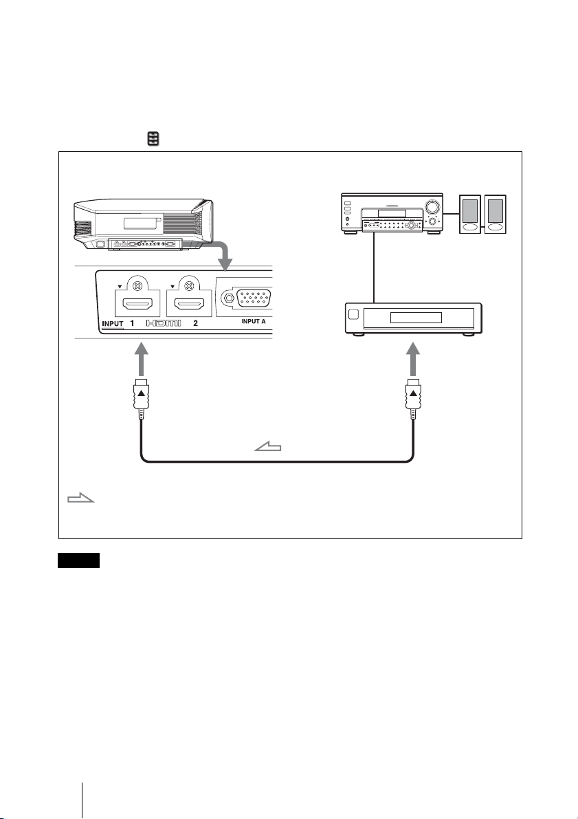
To connect to a DVD player/recorder or Blu-ray Disc player/
recorder equipped with HDMI output
You can enjoy better picture quality by connecting a DVD player/recorder or Blu-ray Disc
player/recorder equipped with HDMI output to the HDMI input of the projector.
Moreover, if you have a Control for HDMI compatible equipment, you can operate the
projector synchronizing with the Control for HDMI compatible equipment. For details,
see the Function menu (1 page 54) and “About the Control for HDMI” (1 page 60).
Right side of the projector
: Video signal flow
Notes
AV amplifier
DVD player/recorder or Bluray Disc player/recorder,
etc., with the HDMI output
HDMI cable (not supplied)
When using an optional HDMI cable, be sure to use
a cable that has acquired the HDMI logo.
Speakers
to HDMI output
• When connecting equipment to the HDMI input of the projector, be sure to use
equipment that have acquired the HDMI logo.
• When connecting an HDMI cable to the projector, make sure the
part of the HDMI input of the projector and the
v mark on the connector of the cable is
V mark on the upper
set at the same position.
• If the picture from equipment connected to the projector with an HDMI cable is not
clear, check the settings of the connected equipment.
............................................................................................................................................................
Control for HDMI is an HDMI standard mutual control function which uses the HDMI CEC
(Consumer Electronics Control) specification.
This projector supports DeepColor, x.v.Color, LipSync and computer input signal of HDMI
standards. It also supports HDCP.
GB
18
Page 19
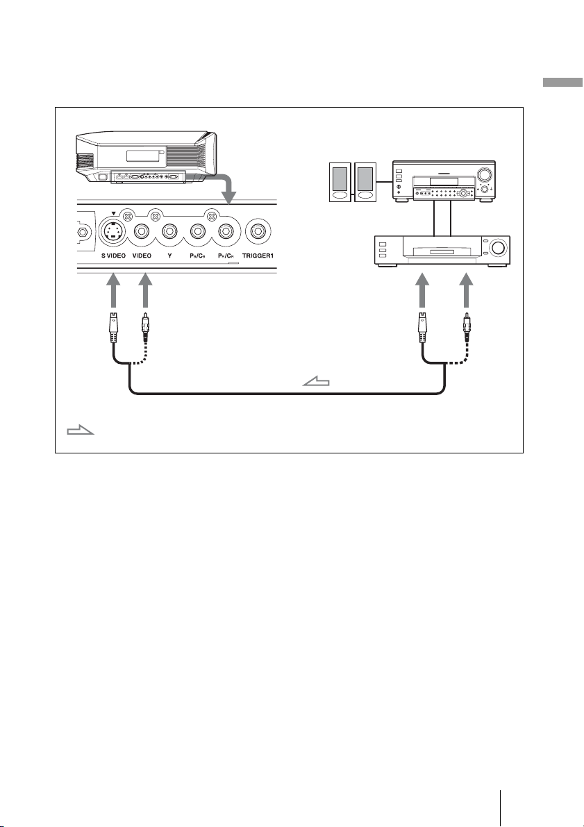
To connect to a VCR equipped with the S video connector or
video connector
You can connect a DVD player/recorder, hard disk video recorder, VCR or laser disk
player, which is not equipped with component video connectors.
Right side of the projector
Connections and Preparations
Speakers
Video equipment
to S video or
video output
S video or video cable (not supplied)
: Video signal flow
AV amplifier
Tip
If you do not know to which connector you should connect the cable, S VIDEO INPUT (S video
input connector) or VIDEO INPUT (video input connector), connect it to S VIDEO to enjoy better
picture quality.
If the equipment to be connected has no S video connector, connect the cable to the video output.
19
GB
Page 20
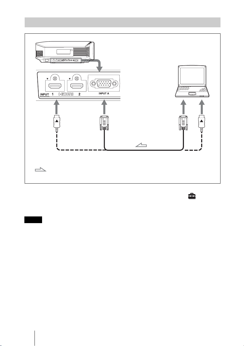
Connecting to a Computer
Right side of the projector
HD-Dsub15 pin cable (not supplied) or HDMI cable (not supplied)
Computer
to monitor output
: Video signal flow
When using an optional HDMI cable, be sure to use
a cable that has acquired the HDMI logo.
Tip
When connecting an HD-Dsub15 pin cable, set “Input-A Signal Sel.” in the Setup menu to
“Auto” or “Computer.” If the input signal does not appear properly, set it to “Computer.” (1
pages 53, 66)
Notes
• When connecting an HDMI cable, make sure the V mark on the upper part of the HDMI
input of the projector and the
v mark on the connector of the cable is set at the same
position.
• If you set your computer, such as a notebook type, to output the signal to both
computer’s display and this equipment, the picture of the equipment may not appear
properly. Set your computer to output the signal to only the external monitor.
For details, refer to the computer’s operating instructions supplied with your computer.
For settings of the computer, consult with the manufacturer of the computer.
• If the picture from equipment connected to the projector with an HDMI cable is not
clear, check the settings of the connected equipment.
GB
20
Page 21
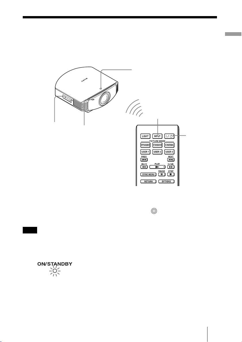
Step 3: Adjusting the Picture Position
Project an image on the screen and then adjust the picture position.
ON/STANDBY indicator
1
4 INPUT button
5, 6, 7
Lens button
Tip
?/1 (on/standby), INPUT, LENS, MENU, and M/m/</,/ (joystick) buttons on the side
The
panel of the projector function the same as those on the remote control.
Remote control
detector
2
Connections and Preparations
?/1 (on/
standby)
switch
Note
Depending on the installation location of the projector, you may not control it with the remote
control. In this case, point the remote control to the screen instead of the projector.
1 After connecting the AC cord to
the projector plug the AC cord
Lights in red.
into a wall outlet.
The ON/STANDBY indicator lights
in red and the projector goes into
standby mode.
21
GB
Page 22
2 Press the ?/1 (on/standby)
r
switch to turn on the projector.
The lens protector will open.
Flashes in green fo
a while (tens of
seconds) and then
lights in green.
The ON/STANDBY indicator flashes
in green, and then lights in green.
When the ON/STANDBY indicator
flashes, “Starting...” appears on the
screen.
3 Turn on the equipment
connected to the projector.
Refer to the operating instructions of
the connected equipment.
4 Press INPUT to project the
picture on the screen.
Each time you press the button, the
input indication and equipment to be
projected change. (1 page 29)
Tips
• You can select the desired language for the menu screen. For details, refer to “Step 4: Selecting
the Menu Language”. (1 page 27)
• When “Auto Input Search” is set to “On” in the Function menu, the input terminal with
effective signals is automatically displayed by pressing INPUT. (1 page 55)
GB
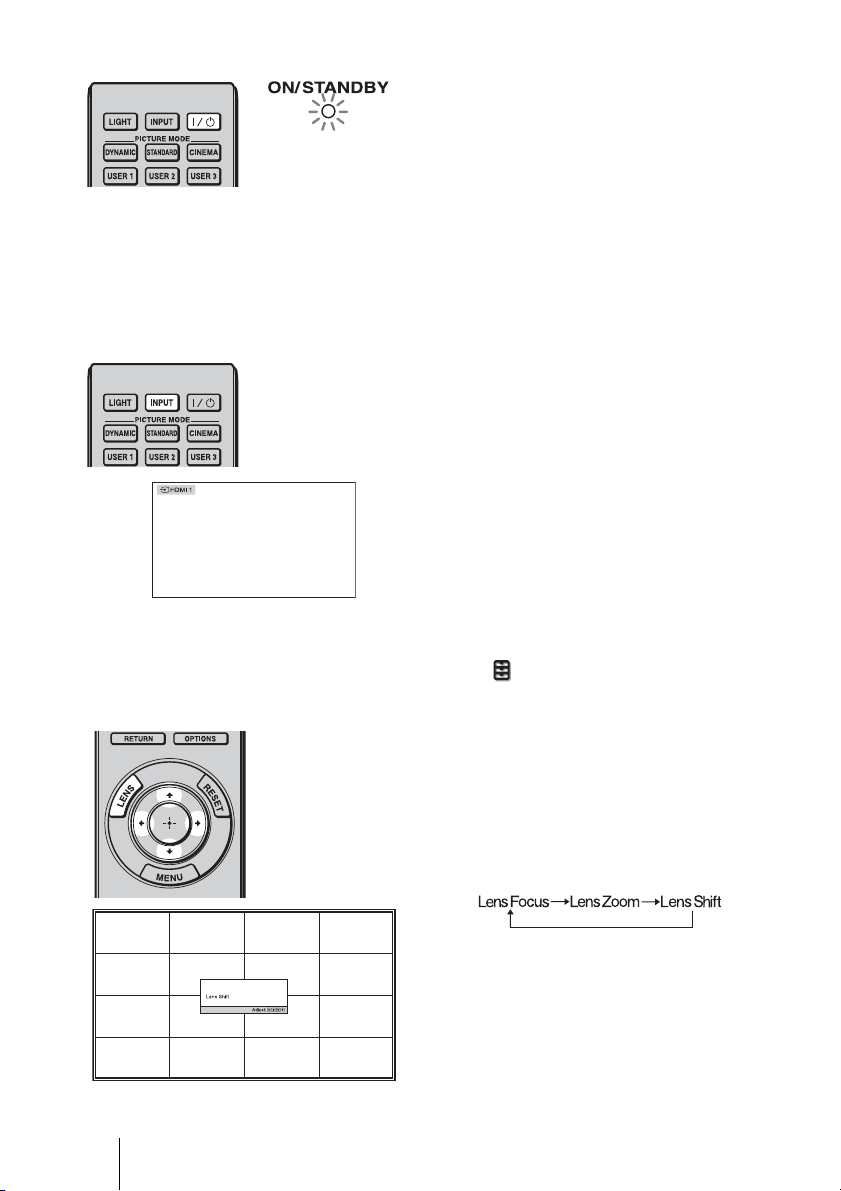
5 Adjust the picture position.
Press the LENS button repeatedly until
the Lens Shift adjustment window (test
pattern) appears. Then adjust the
proper position by pressing the M/m/
</, buttons. Each time you press
the LENS button, the LENS adjustment
window appears in order.
22
Page 23
Tip
When “Lens Control” is set to “Off” on the Installation
position. (1 page 56)
When “Test Pattern” is set to “Off” on the Function menu, the test pattern is not displayed.
(1 page 55)
menu, you cannot adjust the picture
To adjust the horizontal position
Press </,.
The picture projected on the screen moves right or left by a maximum of 25% of the screen
width from the center of the lens.
25% 1 screen width 25%
Top view
: Picture position when moving the picture to the left
at maximum
: Picture position when moving the picture to the
right at maximum
Connections and Preparations
23
GB
Page 24
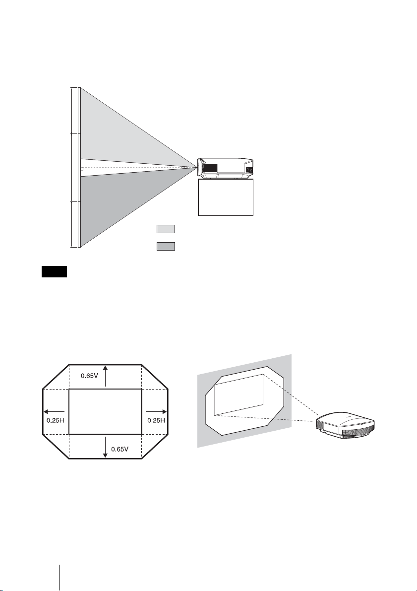
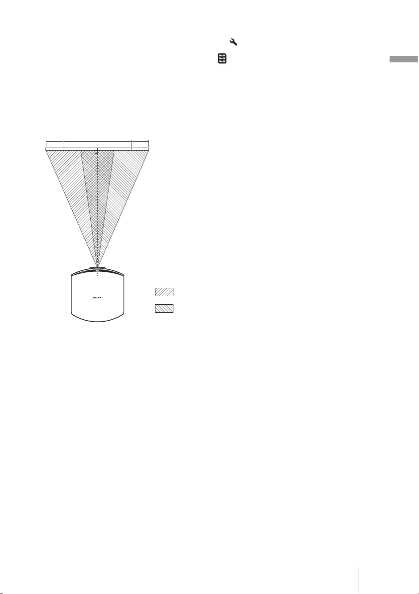
To adjust the vertical position
Press M/m.
The picture projected on the screen moves up or down by a maximum of 65% of the screen
height from the center of the lens.
Side view
65%
1
screen
height
65%
Note
: Picture position when moving the picture upward at
maximum
: Picture position when moving the picture downward at
maximum
The range to move the picture projected on the screen can be adjusted only within the octagon area
illustrated below. In this connection, see “Positioning the Projector and a Screen” (1 page 13) as
well.
Range of movement of
the projected picture
Projected Picture
H: Width of the projected picture
V: Height of the projected picture
GB
24
Page 25
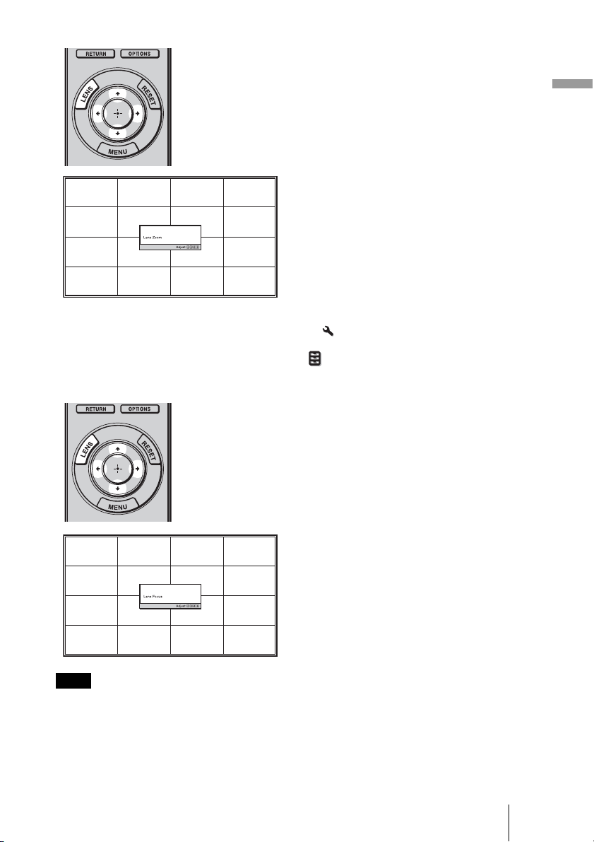
6 Adjust the picture size.
Press the LENS button repeatedly
until the Lens Zoom adjustment
window (test pattern) appears. Then
adjust the size of the picture by
pressing the M/m/</, buttons.
To make the picture larger, press
To make the picture smaller, press
Tip
When “Lens Control” is set to “Off” on the Installation
and the focus. (1 page 56)
When “Test Pattern” is set to “Off” on the Function menu, the test pattern is not displayed.
(1 page 55)
menu, you cannot adjust the picture size
M/,.
m/<.
7 Adjust the focus.
Press the LENS button repeatedly
until the Lens Focus adjustment
window (test pattern) appears. Then
adjust the focus of the picture by
pressing the M/m/</, buttons.
Connections and Preparations
Note
Be sure to adjust the picture size and the focus by using buttons on the remote control or the control
panel of the projector. Never make adjustments by directly turning the lens with your hands, which
may cause damage or malfunction to the projector.
25
GB
Page 26
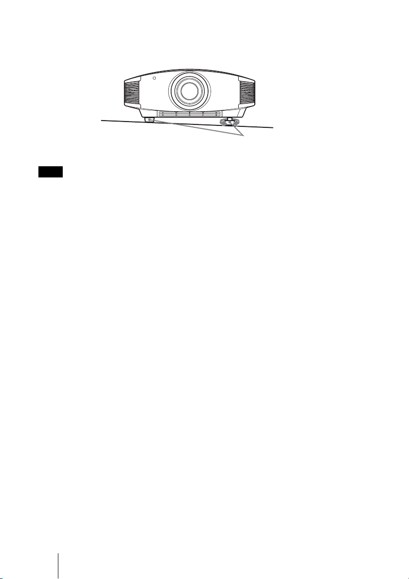
To adjust the tilt of the installation surface
If the projector is installed on an uneven surface, use the adjusters to keep the projector
level.
Turn to adjust.
Adjusters
Note
Be careful not to catch your finger when turning the adjusters.
GB
26
Page 27
Step 4: Selecting the Menu Language
You can select one of 16 languages for displaying the menu and other on-screen displays.
The factory default setting is English. To change the current menu language, set the
desired language with the menu screen.
2,3,4
M/m/</,
(arrow)/ (enter)
buttons
1
MENU button
1 Press MENU.
The menu appears.
Connections and Preparations
27
GB
Page 28
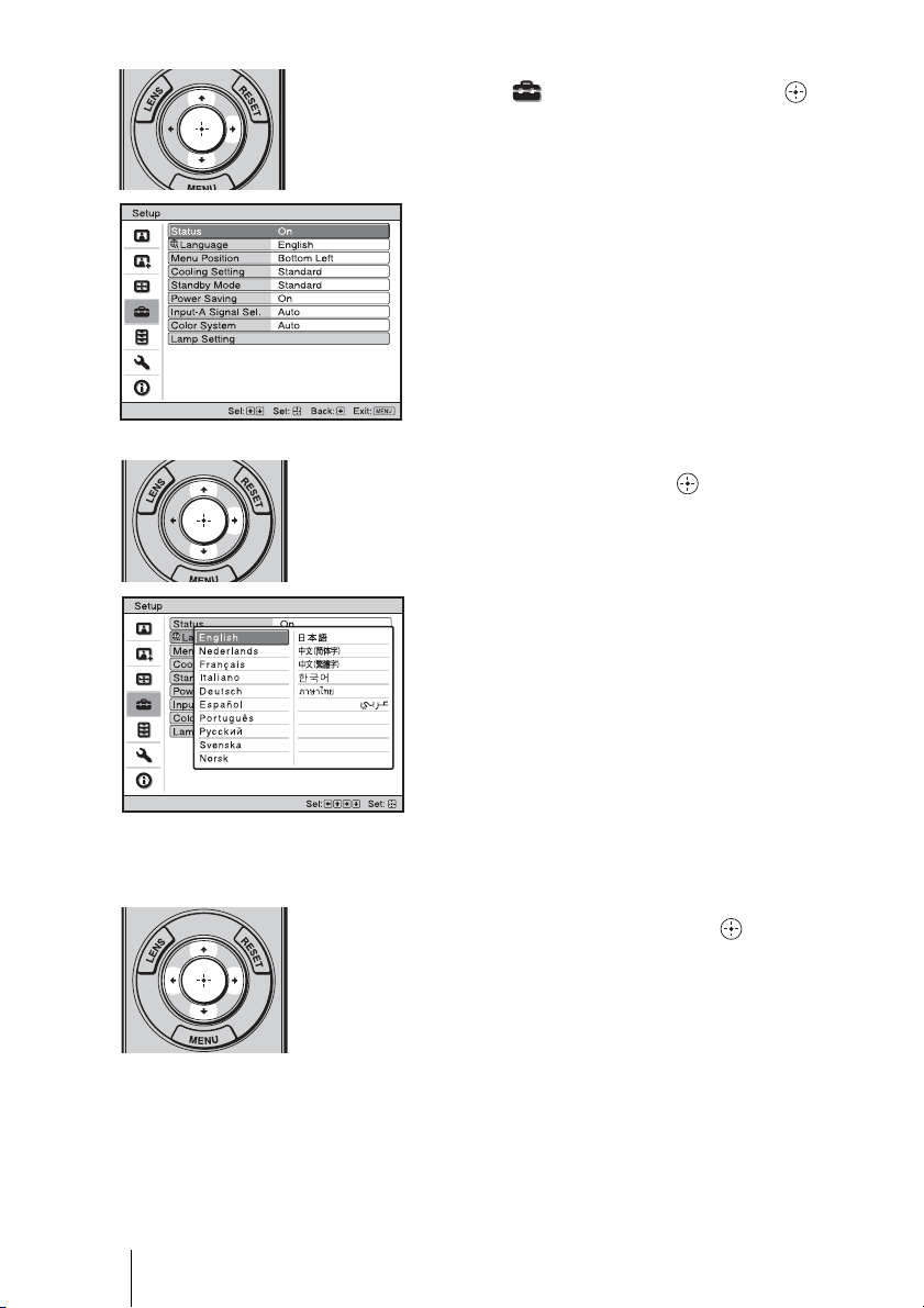
2 Press M/m to select the Setup
menu, and press , or .
The setting items of the selected menu
appears.
3 Press M/m to select “Language,”
and press , or .
GB
4 Press M/m/</, to select a
language, and press .
The menu changes to the selected
language.
To clear the menu
Press MENU.
28
Page 29
Projecting
This section describes how to operate the projector to view the picture from the equipment
connected to the projector. It also describes how to adjust the quality of the picture to suit
your taste.
Projecting the Picture on the Screen
1 Power on both the equipment
and the device connected to the
equipment.
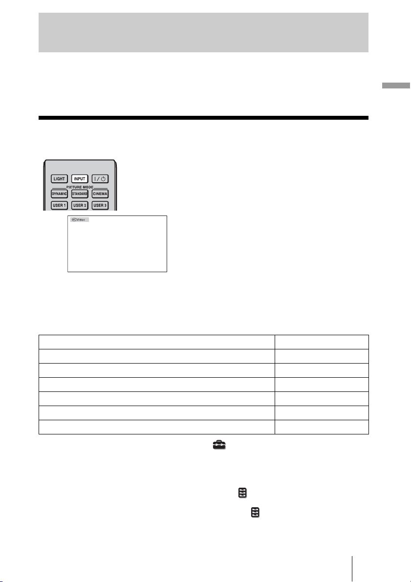
2 Press INPUT repeatedly to
select the input you want to
project on the screen.
Display the indication of the input you
want.
Example: To view the picture
from the video
equipment connected
to the VIDEO INPUT
connector.
Projecting
To view the picture from Press INPUT to display
Video equipment connected to the VIDEO INPUT connector Video
Video equipment connected to the S VIDEO INPUT connector S-Video
Component equipment connected to the Y P
RGB/component equipment connected to the INPUT A connector Input-A*
Equipment connected to the HDMI 1 connector HDMI 1
Equipment connected to the HDMI 2 connector HDMI 2
* Set the “Input-A Signal Sel.” setting in the Setup menu according to the signal input. When
you set it to “Auto,” and cannot display the picture properly, select an appropriate signal
according to the input signal. (1 pages 53, 59)
Tips
• When “Auto Input Search” is set to “On” in the Function menu, the input terminal with
effective signals is automatically displayed by pressing INPUT.
• When the “Control for HDMI” is set to “On” in the Function menu, the HDMI input with
effective signals is automatically displayed, synchronizing with the operation of the equipment
connected to HDMI 1 or HDMI 2 connector of the projector. (Only when the connected equipment
supports Control for HDMI compatible.)
B/CB PR/CR connector Component
29
GB
Page 30
Notes on input of HDMI signal
The projector adjusts the RGB dynamic range of the equipment connected with HDMI
cable to the following to suit the HDMI standard and display in best picture quality.
When video signal is input: Limited (16-235)
When computer signal is input: Full (0-255)
When a signal other than those of HDMI standard is input, the following symptoms may
occur.
• When a video signal is input, the color gradation of the dark area or bright area may
become unclear, or texts may become faded. In this case, switch the RGB dynamic range
of the connected equipment to Limited (16-235). If this adjustment is unavailable, adjust
“Brightness”, “Contrast”, or “Sharpness” in the Picture menu of the projector. (1
page 46)
• When a computer signal is input, the texts may become faded. In this case, adjust the
“Sharpness” in the Picture menu. (1 page 46)
Turning Off the Power
1 Press the ?/1 (on/standby) switch.
A message “POWER OFF?” appears on the screen.
2 Press the ?/1 (on/standby) switch again before the message disappears.
The lens protector will close. Be careful not to catch your fingers or any objects.
The ON/STANDBY indicator flashes in green and the fan continues to run to reduce the
internal heat. First, the ON/STANDBY indicator flashes quickly, during which you will
not be able to light up the ON/STANDBY indicator with the
?/1 (on/standby) switch.
3 Confirm that the fan stops running and the ON/STANDBY indicator lights
in red.
You can turn off the projector by holding the
instead of performing the above steps.
GB
30
?/1 (on/standby) switch for about 1 second,
Page 31

Operating the BRAVIA Sync Compatible Equipment
with the Remote Control of the Projector
BRAVIA Sync
HDMI 1
HDMI 2
compatible equipment
By using the remote control of the projector, you can directly operate the BRAVIA Sync
compatible equipment connected to the HDMI 1 and HDMI 2 INPUT connectors of the
projector. Only the connected equipment that is currently being viewed can be operated.
To operate the BRAVIA Sync compatible equipment, the Control for HDMI setting of the
projector and the connected equipment must both be set. (1 page 54)
Making operations such as
playback or stop
Press ./m, N, >/M, X, x
while viewing pictures.
You can make basic operations such as
playback or stop for the connected
equipment currently being viewed.
Buttons
available to
operate the
BRAVIA
Sync
compatible
equipment
Displaying and operating the
menu of the connected
equipment currently being
viewed
Press SYNC MENU while viewing
pictures.
Operating menu of the connected
equipment currently being viewed is
displayed. Select the menu item to operate
with
/m/</,/ or RETURN.
M
Note
You cannot operate the BRAVIA Sync
compatible equipment with the remote
control of the projector while the menu of
the projector is being displayed.
Projecting
31
GB
Page 32

Using the OPTIONS button to
operate
1 Press OPTIONS while viewing
pictures from the connected
BRAVIA Sync compatible
equipment.
Device Control screen is displayed.
2 Select the desired menu item to
operate with M/m/ .
The screen of the selected menu item is
displayed.
Operate through the menu or select a
menu item with M/m/</,/ .
Switching the input setting to
the BRAVIA Sync compatible
equipment
1 Press SYNC MENU while
viewing pictures from
connected equipment that is not
BRAVIA Sync compatible.
Sync’d HDMI Devices screen is
displayed.
*1
2 Select the name of the
equipment to use with M/m and
press .
The power of the selected equipment
will turn on, and the input setting of the
projector will switch to the terminal of
the selected equipment.
*1
Only the Control for HDMI compatible
equipment connected to HDMI 1 and
HDMI 2 INPUT connectors are
displayed. Connected equipment will
not be displayed when connected to
component input connectors, etc. of the
projector. Also, connected equipment
will not be displayed if it is not
compatible with HDMI Control. AV
amplifier is also not displayed.
*2
Some equipment may take few minutes
for the power to turn on.
Notes
• Only connected equipment compatible with BRAVIA Sync can be operated with the remote
control of the projector.
• Functions available to operate differ depending on the equipment.
• For the functions available to operate, refer to the operating instruction of each equipment.
GB
32
*2
Page 33

Selecting the Wide Screen Mode
You can enjoy various wide screen modes according to the video signal received.
WIDE MODE
button
Original
image
When the Wide
Mode is operated
Press WIDE MODE.
Each time you press the button, you can
select the “Wide Mode” setting.
You can also select it using the menu.
(1 page 50)
Wide Zoom
A 4:3 aspect ratio picture is enlarged
naturally to fill the screen. The upper and
lower portions of the screen are slightly
cut off.
Normal
A 4:3 aspect ratio picture is displayed in
the center of the screen and enlarged to fill
the screen vertically.
Projecting
Squeezed
Full
A picture squeezed to 4:3 aspect ratio is
displayed in its original aspect ratio.
When a 4:3 aspect ratio picture is
displayed, the picture is enlarged
horizontally to fill the 16:9 screen.
Tip
Squeezed: An original 16:9 aspect ratio picture
is recorded horizontally compressed to a 4:3
picture.
33
GB
Page 34

Letterbox picture with side panels
Letterbox picture
When using an
Anamorphic lens
Zoom
A 16:9 aspect ratio picture is enlarged
vertically and horizontally in the same
ratio to fill the screen. Use this mode to
view a letterbox picture or a letterbox
picture with side panels.
If the subtitle of a movie, etc. is hidden
and cannot be seen, adjust the screen with
“Vertical Size” and “V Center” to display
the subtitle. (1 page 51)
Anamorphic Zoom
A 2.35:1 aspect ratio picture is converted
to a normal 16:9 picture on the screen.
This mode is best suited when using a
commercially available Anamorphic lens
which converts a normal 16:9 aspect ratio
picture to a 2.35:1 picture.
Also, 12V signal is output from the
TRIGGER 2 connector and can be used as
sync signal that synchronizes the projector
with the Anamorphic lens.
Full 1 (When a computer
signal is input)
Displays a picture on the whole of the
screen without changing the aspect ratio
of the original picture.
Full 2 (When a computer
signal is input)
Displays a picture on the whole of the
screen.
Notes
• You can adjust the vertical position of the picture with “V Center” and “Vertical Size”
in the Screen menu only when “Zoom” is selected. (1 page 51)
• Depending on the type of Anamorphic lens, part of the screen may be cut off when you
zoom in on the picture. Check the specifications of the Anamorphic lens you use.
GB
34
Page 35

Notes on selecting the wide screen mode
The projector is featured with the Wide Mode. When changing the settings of Wide Mode,
use caution as described below.
• Select the wide screen mode taking into account that changing the aspect ratio of the
original picture will provide a different look from that of the original image.
• Note that if the projector is used for profit or for public viewing, modifying the original
picture by switching to the Wide Mode may constitute an infringement of the rights of
authors or producers, which are legally protected.
Projecting
35
GB
Page 36

Selecting the Picture Viewing Mode
You can select the picture viewing mode that best suits the type of program or room
conditions.
Press one of the
PICTURE MODE buttons
(DYNAMIC, STANDARD,
PICTURE MODE
buttons
DYNAMIC
STANDARD
CINEMA
USER 1,
USER 2
and USER 3
CINEMA and USER 1, USER 2
and USER 3).
DYNAMIC
Vivid picture quality that enhances the
sharpness and contrast of the picture.
STANDARD
Standard picture quality that emphasizes
on naturalness.
CINEMA
Picture quality suited for watching
movies.
USER 1, USER 2 and USER 3
You can adjust the quality of the picture to
suit your taste and store the settings into
the selected memory of the projector.
Press one of the USER 1, USER 2 and
USER 3 buttons, then adjust the picture
by using the buttons on the remote control
or the menus (1 pages 37, 45). The
settings are stored, and you can view the
picture with the adjusted picture quality
by pressing the button.
GB
36
Page 37

Adjusting the Picture Quality
You can easily adjust the picture quality that suits your taste by selecting the adjustment
items with the remote control. The adjusted data can be stored in each picture mode.
Selecting to Directly Adjust the Desired Menu Item
Projecting
GAMMA
CORRECTION
button
BLACK LEVEL
button
ADVANCED IRIS
button
COLOR TEMP
button
COLOR SPACE
button
The following menu items can be
adjusted by using the buttons on
the remote control.
“Gamma Correction”
“Black Level Adj.”
“Advanced Iris”
“Color Temp.”
“Color Space”
Press the following buttons of the desired menu
item repeatedly to adjust the picture quality to
suit your taste. For details on each menu item,
see the Picture menu. (1 page 45)
37
GB
Page 38

Selecting Desired Adjust Menu Items in the Order
1 Press ADJ PIC.
Each time you press the button, the
following adjustment windows are
displayed in sequence.
2
M/m/</,
(arrow) /
(enter) buttons
“Advanced Iris”, “Lamp Control”,
“Contrast”, “Brightness”, “Color”,
“Hue”, “Color Temp.”, “Sharpness”,
“NR”, “MPEG NR”, “Film Mode”,
“Black Level Adj.”, “Gamma
Correction”, “x.v.Color”, “Color
Space”
For details on each adjustment, see the
Picture menu. (1 page 45)
1
ADJ PIC
button
Note
Some adjustment windows cannot be
displayed, depending on the type of input
signal. For details, see “Input Signals and
Adjustable/Setting Items” (1 page 78)
2 Make the setting or adjustment
on an item with M/m/</,.
When changing the adjustment
level
To increase the value, press M/,.
To decrease the value, press m/<.
Example: To adjust the contrast
GB
38
When changing the setting
Press M/m to change the setting.
Page 39

Adjusting the Picture Using Real Color
Processing
The Real Color Processing (RCP) feature allows you to adjust the color and hue of each
target of the projected picture you specify independently. You can thus obtain a picture
more suitable to your taste.
Tip
Freeze the scene of the video source when you are adjusting the picture using Real Color Processing.
1 Press RCP on the remote
control.
Projecting
2, 3, 4, 5
M/m/</,
(arrow) /
(enter) buttons
1
RCP (Real
Color
Processing)
button
Reference palette
2 Press M/m to select “User 1,”
“User 2” or “User 3,” then press
,.
The RCP (Real Color Processing)
window appears.
3 Select the target color you want
to adjust.
Repeat steps 1 and 2 described
below to specify the target color.
1 Press
M/m to select
“Color Select,” then press
to select the color you want to
adjust among “Red,” “Yellow,”
“Green,” “Cyan,” “Blue” and
“Magenta.”
Only the portions that correspond
to the specified color will be
colored and the other portions will
be displayed in black and white.
The reference palette in the RCP
window also shows the adjustable
colors. Select the desired setting to
adjust the color on the projected
image using the reference palette
as a guide.
</,
39
GB
Page 40

2 Press
M/m to select “Position” or
“Range,” and specify it more
delicate color position and color
range you want to adjust using
</,.
4 Adjust the color of the specified
portions.
Press
M/m to select “RCP Color” or
“RCP Hue,” then adjust the color or
hue of the portions selected in step 3 to
suit your taste using
watching the projected picture. The
picture is returned to normal color
during adjustment.
</, while
5 After the adjustment is
complete, press .
The RCP window disappears and the
picture of step 2 is appeared. Then
after a few seconds, normal picture is
restored.
Tip
There are some limitations on selection of
position and range.
Using the Supplied Software to Adjust the
Picture Quality (ImageDirector3)
By using the “ImageDirector3” (supplied as a CD-ROM), you can make the desired
gamma correction from a computer connected to the projector. Connect the REMOTE
connector of the projector with a computer and start-up “ImageDirector3” on the
computer.
For details on how to use the “ImageDirector3”, refer to the Help within the CD-ROM.
Notes
• You need to install the “ImageDirector3” on a computer beforehand.
• When connecting the REMOTE connector with a computer, connect while the power of
the computer and the projector is off.
GB
40
Page 41

Using the Menus
This section describes how to make various adjustments and settings using the menus.
Operation through the Menus
The projector is equipped with an on-screen menu for making various adjustments and
settings. Some of the adjustable/setting items are displayed in a pop-up menu, in a setting
menu or adjustment menu with no main menu, or in the next menu window. If you select
an item name followed by an arrow (
To change the on-screen menu language, see “Step 4: Selecting the Menu Language.”
(1 page 27)
RESET button
2, 3, 4
M/m/</, (arrow) /
1
MENU button
B), the next menu window with setting items appears.
(enter) buttons
Using the Menus
41
GB
Page 42

1 Press MENU.
The menu window appears.
2 Press M/m to select a menu item,
and press , or .
The items that can be set or adjusted
with the selected menu appear. The
item presently selected is shown in
yellow.
GB
42
Page 43

Pop-up menu
Setting menu
3 Press M/m to select an item you
want to set or adjust and press
, or .
The setting items are displayed in a
pop-up menu, in a setting menu, in an
adjustment menu or in the next menu
window.
Setting items
Using the Menus
Adjustment menu
Next menu window
Setting items
43
GB
Page 44

4 Make the setting or adjustment
of an item.
When changing the adjustment
level
To increase the value, press M/,.
To decrease the value, press m/<.
Press to restore the original screen.
When changing the setting
Press M/m to change the setting.
Press to restore the original screen.
You can restore the original screen
using < depending on the selected
item.
Items that cannot be adjusted
Adjustable items differ depending on the
input signal. The items that cannot be
adjusted or set do not appear in the menu.
(1 page 78)
To clear the menu
Press MENU.
To reset the picture that has
been adjusted
Select “Reset” from Picture menu.
To reset the items that have
been adjusted
Select an item in the Menu screen, and
display the pop-up menu, the setting
menu, and the adjustment menu.
Press the RESET on the remote control to
reset only the selected settings to its
factory preset value.
Note
RESET button on the remote control is
available only when the adjustment menu
or the setting menu is selected.
When the screen display appears, select
“Yes” using < and press .
All of the following settings are reset to its
factory preset value.
The settings of “Cinema Black Pro”,
“Contrast”, “Brightness”, “Color”,
“Hue”, “Color Temp”, “Sharpness” and
“Expert Setting” on the Picture
GB
44
menu
Page 45

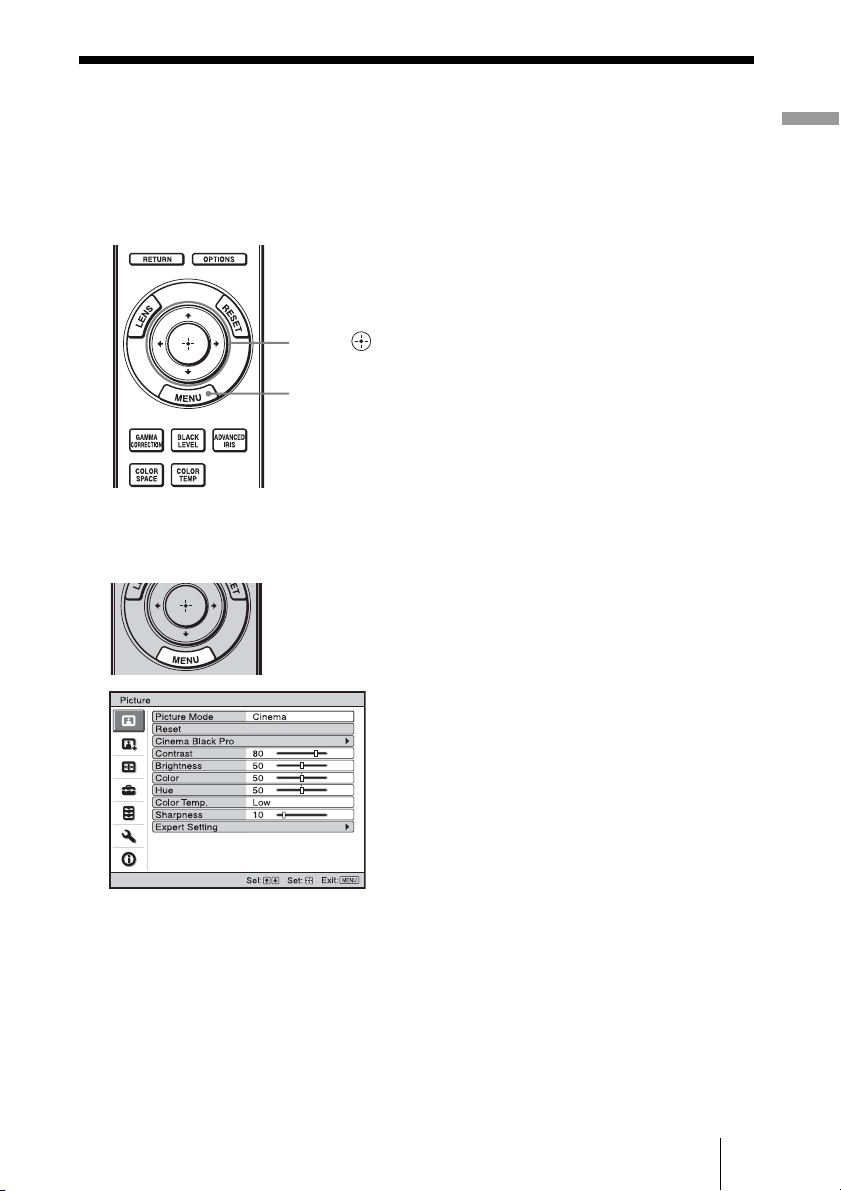
Picture Menu
The Picture menu is used for adjusting the picture.
Note
These items may not be available, depending on the type of input signal. For details, see
“Input Signals and Adjustable/Setting Items” (1 page 78).
Using the Menus
Picture Mode You can select the picture viewing mode that best suits the type of
picture or the environment.
Dynamic: Vivid picture quality that enhances sharpness and contrast of
the picture.
Standard: Standard picture quality that emphasizes on naturalness.
Cinema: Picture quality suited for watching movies.
User 1, User 2, User 3: You can adjust the quality of the picture to suit
your taste and then store the settings. Once the settings are stored, you
can view the picture with the adjusted picture quality by pressing the
PICTURE MODE button on the remote control.
To store the settings
1 Select User 1, User 2, or User 3.
2 Adjust the items you want in the menus.
Tip
You can also store the settings if the picture quality is adjusted in
“Dynamic”, “Standard” or “Cinema”. To reset everything to the factory
settings, select “Reset” from the menu.
45
GB
Page 46

Cinema Black Pro Advanced Iris
Switches the iris function during projection.
Auto 1: Automatically switches to an optimum iris according to a
projected scene. The contrast of the scene is emphasized most.
Auto 2: An optimum iris becomes smaller than when set to “Auto 1”.
The contrast of the scene becomes reduced.
Sensitivity: If “Auto 1” or “Auto 2” is selected, either “Recommend”,
“Fast”, or “Slow” can be selected according to the desired response
speed with Sensitivity Mode.
Manual: Manually adjusts the Iris.
Off: Normal contrast.
Lamp Control
Switches the lamp wattage during projection.
High: Normal wattage.
Low: Enhances the black by reducing the lamp wattage.
Tip
When you switch from “Low” to “High”, the number of turns of the fan
increases, and the fan noise becomes slightly louder.
Contrast Adjusts the white area of pictures (white level).
The higher the setting, the greater the contrast. The lower the setting, the
lower the contrast.
You can make adjustments by pressing the CONTRAST+/– on the
remote control.
Brightness Adjusts the brightness of the picture.
The higher the setting, the brighter the picture. The lower the setting, the
darker the picture.
You can make adjustments by pressing the BRIGHTNESS+/– on the
remote control.
Color Adjusts the intensity of the color density.
The higher the setting, the greater the intensity. The lower the setting, the
lower the intensity.
Hue Adjusts the color tone.
The higher the setting, the more greenish the picture becomes. The lower
the setting, the more reddish the picture becomes.
Color Temp. Adjusts the color temperature.
High: Gives white colors a blue tint.
Middle: Gives a neutral tint between “High” and “Low”.
Low: Gives white colors a red tint.
Custom 1, Custom 2, Custom 3, Custom 4: Enables you to adjust, set,
and store your favorite color temperature.
Sharpness Sharpens the outline of the picture, or reduces the noise.
The higher the setting, the sharper the picture. The lower the setting, the
softer the picture, thus reducing the noise.
You can make adjustments by pressing the SHARPNESS+/– on the
remote control.
GB
46
Page 47

Expert Setting NR (Noise Reduction)
Reduces the roughness or noise of the picture.
Usually, select “Off”.
If the picture is rough or noisy, select a setting from among “Low”,
“Middle” or “High” according to the input signal source.
MPEG NR (MPEG Noise Reduction)
Reduces block noise and mosquito noise, in particular in digital
signals.
Block NR: Reduces digital noise that appears in mosaic-like pattern.
Mosquito NR: Reduces digital noise that appears near the outline of the
picture.
Film Mode
According to the film source you have selected, make a setting for
playback.
Auto: Reproduces a 2-3 or 2-2 Pull-Down format video signal, such as
film sources, in a smooth picture movement. When a video signal
other than 2-3 or 2-2 Pull-Down format is input, the picture is played
back in progressive format.
Off: Plays back the picture in progressive format without detecting
video signals automatically.
Black Level Adj. (Adjust)
Produces a bolder, dynamic picture.
Set according to the input signal source.
High: Gives higher emphasis to the black color.
Low: Gives lower emphasis to the black color.
Off: Cancels this feature.
Gamma Correction
Adjusts the response characteristics of the tone of the picture.
Select a favorite tone from 6 options.
Gamma 1: Makes the scene much brighter overall.
Gamma 2: Makes the scene brighter overall.
Gamma 3: Makes the scene slightly brighter overall.
Gamma 4: Makes the scene darker overall.
Gamma 5: Gamma curve is set to a setting that makes the dark area of
the screen brighter and is suited for when using a matt projection
screen.
Gamma 6: Gamma curve is set to a setting that makes the bright area of
the screen even brighter.
Off: Gamma Correction is “Off”
Using the specified controller, “ImageDirector3” (supplied as a CDROM) allows you to adjust, set, and store a favorite tone in a computer.
For detailed information on “ImageDirector3”, refer to the Help
provided on the supplied CD-ROM in the computer.
x.v.Color
Set this item when playing back an x.v.Color video signal.
Set this item to “On” when connecting the projector with equipment that
supports x.v.Color and playing back an x.v.Color video signal.
For details on x.v.Color, see “About the x.v.Color” (1 page 61).
Using the Menus
47
GB
Page 48

Color Space
You can convert the range of color reproduction.
Normal: Converts the color tones to those that match the specifications
of Hi-Vision signal.
Wide: Reproduces more natural color tones in a wider range of color
reproduction, compared to “Normal”.
GB
48
Page 49

Advanced Picture Menu
The Advanced Picture is used for adjusting the picture more.
Using the Menus
RCP (Real Color
Processing)
You can adjust the color and hue of each selected portion of the
picture independently.
User 1, User 2, User 3: You can adjust the picture using Real Color
Processing and store the settings. Once the settings are stored, you can
view the picture with the adjusted picture quality.
Off: Cancels this feature.
For details, see “Adjusting the Picture Using Real Color Processing”.
(1 page 39)
49
GB
Page 50

Screen Menu
The Screen menu is used to adjust the input signal. You can adjust the size of the picture,
and select wide screen mode, etc.
.
Note
These items may not be available, depending on the type of input signal. For details, see
“Input Signals and Adjustable/Setting Items” (1 page 78).
Wide Mode
(Video signal)
Wide Mode
(Computer signal)
You can set the aspect ratio of the picture to be displayed for the
current input signal. (1 page 33) This item is enabled only when a
video signal (preset memory numbers 1 to 14) (1 pages 75, 76) is
input.
Wide Zoom: A 4:3 aspect ratio picture is enlarged naturally to fill the
screen. The upper and lower portions of the screen are slightly cut off.
Normal: A 4:3 aspect ratio picture is displayed in the center of the
screen and enlarged to fill the screen vertically.
Full: A picture squeezed to 4:3 aspect ratio is displayed in its original
aspect ratio. When a 4:3 aspect ratio picture is displayed, the picture is
enlarged horizontally to fill the 16:9 screen.
Zoom: A 16:9 aspect ratio picture is enlarged vertically and horizontally
in the same ratio to fill the screen.
Anamorphic Zoom: A 2.35:1 aspect ratio picture is converted to a
normal 16:9 picture on the screen. This mode is best suited when
using a commercially available Anamorphic lens which converts a
normal 16:9 aspect ratio picture to a 2.35:1 picture. When set to this
setting, only 12 V signal is output from the TRIGGER 2 connector.
(1 pages 7, 34)
You can switch settings by pressing WIDE MODE on the remote
control.
You can set the aspect ratio of the picture to be displayed for the
current input signal. (1 page 34) This item is enabled only when a
computer signal is input.
Full 1: Displays a picture on the whole of the screen without changing
the aspect ratio of the original picture.
Full 2: Displays a picture on the whole of the screen.
Zoom: A 16:9 aspect ratio picture is enlarged vertically and horizontally
in the same ratio to fill the screen.
You can switch settings by pressing WIDE MODE on the remote
control.
GB
50
Page 51

Over Scan Hides the outline of the picture.
On: Hides the outline of the input picture. Select this setting when noise
appears along the edge of the picture.
Off: Projects the whole of the input picture.
Tip
To display the displayable region within the four directions of the screen,
refer to “Blanking” on the Installation menu (1 page 57).
Screen Area Selects the size of the picture when a Hi-Vision picture is
overscanned.
Full: Expands the picture on the whole of the screen.
Through: Does not expands the picture on the whole of the screen.
V Center Adjust the whole picture by moving up and down on the screen.
As the selected number increases, the screen moves up, and as the
selected number decreases, the screen moves down.
Vertical Size Reduces or enlarges the picture vertically.
The screen is enlarged as the setting increases and reduced as the setting
decreases. If the subtitle of a movie, etc. cannot be seen, use this together
with “V Center”.
Adjust Signal You can adjust the input signal.
APA: Adjusts “Phase”, “Pitch”, and “Shift” automatically to a position
that suits the image signal for pictures from a computer.
Phase: Adjusts the dot phase and the phase of computer signal of
pictures from a computer. Adjusts the picture to the point where it
looks clearest.
Pitch: Adjusts the horizontal size of the picture from a computer.
As the number increases, the picture becomes wider, and as the
number decreases, the picture becomes narrower. Adjust the setting to
match the number of dots of the input signal.
Shift: Adjusts the position of the picture.
H: As the setting for H (horizontal) increases, the picture moves
to the right, and as the setting decreases, the picture moves to
the left. Use < / , to adjust the horizontal position.
V: As the setting for V (vertical) increases, the picture moves up,
and as the setting decreases, the picture moves down. Use M /
m to adjust the vertical position.
Using the Menus
51
GB
Page 52

Setup Menu
The Setup menu is used to change the factory preset settings, etc.
Status Sets whether or not the on-screen display is displayed.
Language Selects the language used in the menu and on-screen displays.
Menu Position You can change the position to display the menu on the upper
Cooling Setting Use this item when using the projector at high altitudes.
Standby Mode Lowers the power consumption in standby.
Set to “Off” to turn off the on-screen displays except for certain
menus, message when turning off the power, and warning messages.
Available languages are: English, Dutch, French, Italian, German,
Spanish, Portuguese, Russian, Swedish, Norwegian, Japanese,
Chinese (Simplified Chinese), Chinese (Traditional Chinese),
Korean, Thai and Arabic.
screen.
Bottom Left: Displays the menu on the bottom left area of the
screen.
Center: Displays the menu on the center of the screen.
High: Use this setting when using the projector at an altitude of
1,500 m or higher.
Standard: Use this setting when using the projector at normal
altitudes.
Note
When this item is set to “High”, the fan noise becomes slightly
louder since the number of fan rotation increases.
When set to “Standard”, the power consumption in standby becomes
normal.
When set to “Low”, the power consumption in standby is lowered.
Note
When this item is set to “Low”, the Control for HDMI function will
not operate.
GB
52
Page 53

Power Saving Sets the power saving mode.
When set to “On”, the projector goes into power saving mode if no
signal is input for 10 minutes. At that time, the ON/STANDBY
indicator lights in orange, then the screen becomes dark. In power
saving mode, the power saving mode is cancelled if a signal is input
or any button on the projector or the remote control is pressed. If you
do not want to set the projector to power saving mode, select “Off”.
Input-A Signal Sel. Selects the type of signal input from the equipment connected to
the INPUT A connector.
Selects the type of signal input from the equipment by selecting
“Input-A” with the INPUT button.
Auto: Selects the input signal type automatically.
Computer: Inputs the signal from a computer.
Video GBR: Inputs the signal from a TV game or HDTV broadcast.
Component: Inputs the component signal from a DVD player/
recorder, Blu-ray Disc player/recorder, digital tuner, etc.
Note
When the input signal is not displayed correctly with this item set to
“Auto,” select the item according to the input signal.
Color System Selects the color system of the input signal.
Auto: Selects the color system of the input signal automatically
from among NTSC
3.58, PAL, SECAM, NTSC4.43, PAL-M,
PAL- N, o r PAL 60.
“NTSC3.58”–“PAL -N ”: Allows you to set the color system to the
selected system manually.
Note
Normally, set this to “Auto.” If the picture is distorted or colorless,
select the color system appropriate for the input signal.
Lamp Setting When replacing the lamps, set the desired lamp setting.
(1 page 70)
Using the Menus
53
GB
Page 54

Function Menu
The Function menu is used for changing the settings of the various functions of the
projector.
HDMI 1
HDMI 2
HDMI Setting You can change the settings of the Control for HDMI function.
Control for HDMI: Selects the function whether to turn the Control
for HDMI function effective when the HDMI 1 and HDMI 2
connectors are connected to a Control for HDMI compatible
equipment.
When set to “On”, the following are available.
• The operation of the projector and the connected Control for
HDMI compatible equipment will synchronize with each other.
• The Control for HDMI setting of Sony equipment (AV
amplifier, video, etc.), which is compatible with “Control for
HDMI - Easy Setting”*, will also be effective.
The factory default setting is “Off”.
Device Auto Power Off: Sets whether to also turn the power of the
connected Control for HDMI compatible equipment off when you
turn the power of the projector off.
When set to “On”, the equipment will synchronize and turn off
when the power of the projector turns off.
The factory default setting is “Off”.
PJ Auto Power On: Sets whether to turn the power of the projector
on when you operate the connected Control for HDMI compatible
equipment.
When set to “On”, the power of the projector will automatically
turn on when the power of the connected equipment is turned on
or when making operations such as playback.
The factory default setting is “Off”.
GB
54
Page 55

Device List: Lists all the Control for HDMI compatible equipment
connected to the projector.
All equipment listed (except AV amplifier) can be selected with
SYNC MENU of the remote control of the projector. When
“Enable” is selected, the Control for HDMI setting of Sony
equipment (AV amplifier, video, etc.), which is compatible with
“Control for HDMI - Easy Setting”, will also be effective.
Notes
• When “Standby Mode” is set to “Low”, this item will not operate
(This will not be displayed on the menu screen).
• To use the “Control for HDMI - Easy Setting” function, the
connected equipment must be compatible with “Control for HDMI
- Easy Setting” and the power has to be “On”. For details, see
“About the Control for HDMI” (1 page 60).
* “Control for HDMI - Easy Setting” is a function that makes the
Control for HDMI setting of equipment connected to HDMI input
of the projector effective as well when the Control for HDMI
setting of the projector is effective. This function is only available
between compatible Sony equipment, and some equipment may
not be compatible.
Auto Input Search Detects the input signal and displays the detected input signal
automatically when the INPUT button is pressed.
When set to “On”, the input terminal with effective signal is
automatically detected and pictures are displayed by pressing
INPUT. Input signals are detected in the sequence of HDMI 1,
HDMI 2, Video, S-video, Input-A and Component, and the input
terminal that follows the currently selected input terminal will be
detected. Set this to “Off” when you want to select an input selector
with no input signal, or you want to switch the setting manually.
Tes t P attern Displays the test pattern.
When set to “On,” a test pattern appears on the screen to be used
when adjusting the lens with “Lens Focus,” “Lens Zoom,” and “Lens
Shift,” or correcting the screen proportions with “V Keystone.” A
test pattern does not appear when this item is set to “Off.”
Tip
While the test pattern is displayed, it is only displayed in green to
allow you to adjust the focus easily.
Background Selects the background color of the screen when no signal is input.
You can select “Black” or “Blue”.
Using the Menus
55
GB
Page 56

Installation Menu
The Installation menu is used for changing the installation settings.
V Keystone Corrects the vertical trapezoidal distortion of the picture.
Image Flip Flips the picture on the screen horizontally and/or vertically.
Lens Control Avoids any operation of the lens such as “Lens Focus,” “Lens
IR Receiver Selects the remote control detectors (IR Receiver) on the front
When the bottom of the trapezoid is longer than the top ( ):
Sets a lower value (– direction)
When the top of the trapezoid is longer than the bottom ( ):
Sets a higher value (+ direction).
Note
Depending on the picture position adjusted with the lens shift
feature, the aspect ratio of the picture may change from the original
or picture distortion may occur with V Keystone adjustment.
Off: The picture does not flip.
HV: Flips the picture horizontally and vertically.
H: Flips the picture horizontally.
V: Flips the picture vertically.
Use this item for installation for the backside projection or ceiling
installation.
Zoom,” and “Lens Shift,” by mistake.
When set to “On,” you can adjust the projection lens using “Lens
Focus,” “Lens Zoom,” and “Lens Shift.” After you make this
adjustment, it is recommended that you set this item to “Off” to
avoid any operation of the lens.
and rear of the projector.
Front & Rear: Activates both the front and rear detectors.
Front: Activates the front detector only.
Rear: Activates the rear detector only.
GB
56
Page 57

Blanking This feature allows you to adjust the displayable region within
the four directions of the screen.
Select each screen edge “Left / Right / Top / Bottom” on the
Blanking adjustment screen with M / m buttons. Adjust the desired
Blanking value with < / , button.
Note
When both the “Blanking” and the “V Keystone” are adjusted at the
same time, the “Blanking” cannot be adjusted correctly. When using
the “Blanking”, make sure that you set the “V Keystone” to “0”.
Panel Alignment This feature allows you to adjust the gaps in the color of
characters or the picture.
When set to “On”, the “Adjust Color” and the “Pattern Color” can be
assigned and adjusted.
Adjust Item: Selects how to make adjustments from below.
Shift: Shifts the whole picture and makes adjustments.
Zone: Selects the desired range and makes adjustments.
Adjust Color: Assigns the desired color to adjust the gaps in color.
Select “R” (Red) or “B” (Blue) to make adjustments based on
“G” (Green).
Pattern Color: Select “R/G” (Red and Green) or “R/G/B” (White,
all colors) when the “Adjust Color” is “R” (Red). Select “B/G”
(Blue and Green) or “R/G/B” (White, all colors) when the “Adjust
Color” is “B” (Blue).
Adjust: The shift adjustment and zone adjustment of the color
selected in “Adjust Color” can be made with < / ,, M / m
buttons.
When “Shift” is selected: Assign the settings of the horizontal
direction (H) with < / , buttons and the vertical direction (V)
with M / m buttons on the shift adjustment screen.
Using the Menus
When “Zone” is selected: Select the position to adjust with
< / , buttons for the horizontal position (H position) and M / m
buttons for the vertical position (V position), then press .
57
GB
Page 58

Set the amount to adjust with < / , buttons for the horizontal
direction (H direction) and with M / m buttons for the vertical
direction (V direction). You can select the position to adjust again by
pressing .
Reset: Returns to the factory settings.
Note
Depending on the adjustments made above, colors may become
uneven or the resolution may change.
GB
58
Page 59

Information Menu
The Information menu displays the model name, serial number, the horizontal and vertical
frequencies of the input signal and the cumulated hours of usage of the lamp.
Model name: VPL-VW70
Serial No.
Memory No.
Signal type
Model name Displays the model name (VPL-VW70).
Serial No. Displays the serial number.
fH (horizontal frequency) Displays the horizontal frequency of the input signal.
fV (vertical frequency) Displays the vertical frequency of the input signal.
Memory No. Displays the preset memory number of the input signal.
Signal type Displays the type of the input signal.
Lamp Timer Indicates how long the lamp has been turned on (total usage).
Notes
• fH (horizontal frequency) and fV(vertical frequency) may not be displayed depending
on the input signal used on the projector.
• You cannot change the displays listed above.
Using the Menus
About the Preset Memory No.
This projector has 38 types of preset data for input signals (the preset memory). When the
preset signal is input, the projector automatically detects the signal type and recalls the
data for the signal from the preset memory to adjust it to an optimum picture. The memory
number and signal type of that signal are displayed in the Information menu.
You can also adjust the preset data through the Screen menu.
This projector also contains 20 different user memories beside the preset memories used
for inputting analog computer signals. You can save input signals that have not been preset
on these user memories.
When an unpreset signal is input for the first time, a memory number is displayed as 0.
When you adjust the data of the signal in the Screen menu, it will be registered to the
projector. If more than 20 user memories are registered, the newest memory always
overwrites the oldest one.
See the chart on page 75 to find if the signal is registered to the preset memory.
Note
When the aspect ratio of input signal does not match the screen size, a part of the screen is displayed in black.
59
GB
Page 60

Others
This section describes about the other functions, how to solve the problems, how to
replace the lamp and air filter, etc.
Setting the Control for HDMI
About the Control for
HDMI
What is the Control for HDMI?
Control for HDMI is an HDMI standard
mutual control function which uses the
HDMI CEC (Consumer Electronics
Control) specification. By connecting a
variety of Sony Control for HDMI
compatible equipment such as a hard disk
Blu-ray Disc player, a DVD player/recorder,
an AV amplifier, etc. to a Sony Control for
HDMI compatible TV or a projector with an
HDMI cable, the equipment connected will
synchronize with the TV or the projector
when either is operated.
Using the Control for HDMI
function
• Connect and assign the settings of each
equipment appropriately.
• Do not turn off the main power of the
equipment.
• Set the input setting of the projector to the
HDMI input which the equipment is
connected.
• Check if the picture from the equipment
appears appropriately on the projector.
• The Control for HDMI function is
available only between Sony Control for
HDMI compatible equipment.
Connecting a Control for HDMI
compatible equipment
Use an HDMI cable to connect the projector
and the Control for HDMI compatible
equipment. Use a cable that has acquired the
HDMI logo.
Be sure to assign the appropriate
connections for both the projector and the
Control for HDMI compatible equipment
connected to the projector. For settings of
the projector, see page 54. For settings of the
Control for HDMI compatible equipment
connected to the projector, refer to its
operational instructions. When a Sony
equipment that is compatible with the
“Control for HDMI - Easy Setting” is
connected to the HDMI input of the
projector, if you turn the Control for HDMI
function setting of the projector on, the
Control for HDMI function setting of the
connected equipment will also turn on.
What you can do with the
Control for HDMI
• Basic operations (playback, stop, menu
operations, etc.) of the connected
equipment is available by using the remote
control of the projector.
• By turning on or playing back the
connected equipment, the projector will
turn on and the input setting will switch to
the terminal of the connected equipment
automatically.
• By turning the power of the projector off,
the power of the connected equipment will
also turn off automatically.
• By selecting equipment connected to the
projector desired to operate with SYNC
MENU button on the remote control of the
projector, the power of the selected
equipment will turn on and the input will
switch to the terminal of the connected
equipment automatically.
• By changing the language setting of the
projector, the language setting of the
connected equipment will also change to
the same language automatically.
GB
60
Page 61

Notes
• The available functions of the Control for
HDMI differ depending on each
equipment. Refer to the operating
instruction of each equipment.
• Some synchronization may be available
with equipment of other brands with
similar functions, but it is not guaranteed.
About the x.v.Color
• “x.v.Color” is a promotion name given to
the products that have the capability to
realize a wide color space based on the
xvYCC specifications and is a trademark
of Sony Corporation.
• xvYCC is an international standard of the
technical specifications of the extendedgamut color space for video signals. The
color gamut of xvYCC is wider than the
one of sRGB that is used with the current
television system.
Others
61
GB
Page 62

Troubleshooting
If the projector appears to be operating erratically, try to diagnose and correct the problem
using the following instructions. If the problem persists, consult with qualified Sony
personnel.
Power
Symptom Cause and Remedy
The power is not turned on. c The power may not turn on if you turn the power off with ?/1
Picture
Symptom Cause and Remedy
No picture. c Check that the proper connections have been made.
The picture from the
INPUT A connector is
colored strange.
The picture from the
VIDEO INPUT or
S VIDEO INPUT
connector is colored
strange.
The bright area of the
picture may become
unclear or texts may
become faded. (When
HDMI video signal is
input)
The texts may become
faded when connected with
a computer. (When
computer signal is input)
(on/standby) switch and turn it on again in a short time.
After about 1 minute, turn the power on.
c Close the lamp cover securely, then tighten the screws securely.
(1 page 69)
c Close the filter holder securely. (1 page 70)
c Check warning indicators. (1 page 65)
(1 page 17)
c Select the input source correctly using the INPUT button.
(1 page 29)
c Set the computer signal to output from an external monitor.
c Set the computer signal to output only to an external monitor.
c Select “Computer,” “Component” or “Video GBR” for “Input-A
Signal Sel.” on the Setup menu according to the input
signal. (1 page 53)
c Select “Computer,” “Component” or “Video GBR” for “Input-A
Signal Sel.” on the Setup menu according to the input
signal. (1 page 53)
c Adjust the picture of the Picture menu. (1 page 45)
c Set “Color System” in the Setup menu to match the color
system being input. (1 page 53)
c This symptom may occur when a signal other than those of
HDMI standard is input. (1 page 30) Switch the RGB dynamic
range of the connected equipment to Limited (16-235). If this
adjustment is unavailable, adjust “Brightness”, “Contrast”, or
“Sharpness” in the Picture menu of the projector.
(1 page 46)
c This symptom may occur when a signal other than those of
HDMI standard is input. (1 page 30) Adjust “Sharpness” in the
Picture menu. (1 page 46)
GB
62
Page 63

Symptom Cause and Remedy
The picture is too dark. c Adjust the “Contrast” or “Brightness” of the Picture menu
The picture is not clear. c Adjust the focus. (1 page 25)
The picture flickers. c For pictures from a computer, activate “APA” and adjust the
The color of characters or
the picture is not
appropriate.
Image is left on the screen.
(image retention)
properly. (1 page 46)
c Condensation has accumulated on the lens. Leave the projector
for about 2 hours with the power on.
current input signal.
c Adjust “Phase” for “Adjust Signal” in the Screen menu
properly. (1 page 51)
c Select the desired color registration in “Panel Alignment” of
Installation menu (1 page 57).
c When high contrast non-moving images are displayed for a long
period of time, there may be some image retention on the
screen. This is only a temporary condition. Turning off the
power for a while will eliminate the retained image.
On-screen display
Symptom Cause and Remedy
On-screen display does not
appear.
The model name does not
disappear from the screen.
c Set “Status” in the Setup menu to “On.” (1 page 52)
c Check if the ON/STANDBY indicator should light in green.
c The display mode of the projector may be set at the time of
purchase. Consult with your local dealer or qualified Sony
personnel.
Others
Remote control
Symptom Cause and Remedy
The remote control does
not work.
c Batteries could be weak. Replace them with new batteries.
(1 page 10)
c Insert the batteries with the correct polarities. (1 page 10)
c If there is a fluorescent lamp near the remote control detector, the
projector may work improperly or inadvertently.
c Set “IR Receiver” to “Front & Rear” on the Installation menu
(1 page 56).
63
GB
Page 64

Others
Symptom Cause and Remedy
The fan is noisy. c Check the setting of “Cooling Setting” in the Setup menu.
The lens shift cannot be
adjusted.
(1 page 52)
c Make sure that the room temperature is not too high.
c Check the installation conditions. (1 page 11)
The number of fan rotation increases to maintain the product
reliability of the projector’s components in a room, where the
temperature is higher than normal. The fan noise becomes
slightly louder. The approximate normal temperature is 25°C.
c The lens shift cannot be adjusted over the range of movement.
Adjust the lens shift within the range of movement. (1
pages 13, 24).
GB
64
Page 65

Warning Indicators
The ON/STANDBY or LAMP/COVER indicator lights up or flashes if there is any
trouble with your projector.
LAMP/COVER indicator
Symptom Cause and Remedy
LAMP/COVER flashes in
red. (A repetition rate of 2
flashes)
LAMP/COVER flashes in
red. (A repetition rate of 3
flashes)
ON/STANDBY flashes in
red. (A repetition rate of 4
flashes)
ON/STANDBY flashes in
red. (A repetition rate of 2
flashes)
ON/STANDBY flashes in
red. (A repetition rate of 6
flashes)
c Close the lamp cover securely, then tighten the screws securely.
(1 page 69)
c Close the filter holder securely. (1 page 70)
c The lamp has reached the end of its useful lifespan. Replace the
lamp. (1 page 68)
c The lamp has reached a high temperature. Wait until the lamp
cools, and then turn on the power again.
c The fan is broken. Consult with qualified Sony personnel.
c The internal temperature is unusually high. Check to ensure that
if nothing is blocking the ventilation holes or whether or not the
projector is being used at high altitudes.
c Press the
power is not turned on, disconnect the AC power cord, then
confirm the ON/STANDBY indicator is turned off. After about
10 seconds, reconnect the AC power cord and turn on the power
again. If the indicators still light up, the electrical system has a
problem. Consult with qualified Sony personnel.
?/1 (on/standby) switch to turn on the projector. If the
Others
ON/STANDBY indicator
65
GB
Page 66

Symptom Cause and Remedy
ON/STANDBY flashes in
red. (A repetition rate of 5
times)
Note
When a warning indicator other than the above starts flashing, and the symptom persists even after
carrying out the above methods, consult with qualified Sony personnel.
c The lens protector is not fully open. Turn the power of the
projector off and then on again. If the lens protector still does not
fully open, consult with qualified Sony personnel.
Tip
In an urgent situation, refer to the illustration below to open the lens
protector with your hands. Press the
the power on and operate the projector.
?/1 (on/standby) switch to turn
Message Lists
Warning messages
Message Cause and Remedy
High temp.! Lamp off in 1
min.
Frequency is out of range! c Frequency is out of range. Input a signal that is within the
Please check Input-A
Signal Sel.
Please replace the Lamp/
Filter.
c Turn off the pow er.
c Check to ensure that nothing is blocking the ventilation holes.
(1 page 12)
acceptable frequency range of the projector. (1 page 75)
c Set “Input-A Signal Sel.” in the Setup menu to
“Computer” when an RGB signal is input from a computer.
(1 page 53)
c It is time to replace the lamp. Replace the lamp. (1 page 68)
c Also, replace the air filter too. Restart cleaning the ventilation
holes (intake). (1 page 68)
If this message appears again after you replace the lamp and
filter, the lamp replacement process is not complete. Check the
lamp replacement process. (1 page 68)
Note
To clear this message, press any button either on the remote control
or the control panel of the projector once.
GB
66
Page 67

Message Cause and Remedy
Please clean the filter. c It is time to clean the air filter. Clean the air filter. (1 page 71)
Note
To clear this message, press any button either on the remote control
or the control panel of the projector once.
Please clean the filter. Have
you finished? Yes No
Projector temperature is
high. Cooling Setting
should be “High” if
projector is being used at
high altitude.
c It is time to clean the air filter. Clean the air filter. (1 page 71)
c If you cleaned the air filter, select “Yes.” If you did not clean the
air filter, select “No.”
c Check to ensure that the ventilation holes on the unit are not
covered. (1 page 12)
c When using the projector at high altitude, set the “Cooling
Setting” to “High”. (1 page 52)
Note
When temperature inside the projector remains high, the “Cooling
Setting” is switched to “High” in 1 minute, then the fan speed
increases.
Caution messages
Message Cause and Remedy
c No signal is input in the selected input. Check connections.
x
Not applicable! c Press the appropriate button.
(1 page 17)
c The operation to be activated by the button is currently
prohibited.
Others
67
GB
Page 68

Replacing the Lamp
and the Air Filter and
Cleaning the
Ventilation Holes
(intake)
Tools you need to get started:
• Projector Lamp LMP-H201 (Optional)
• Standard Phillips screwdriver
• Cloth (for scratch protection)
The lamp used for the light source has a
certain lifespan. When the lamp dims, the
color balance of the picture becomes strange,
or “Please replace the Lamp/Filter.” appears
on the screen, the lamp may be exhausted.
Replace the lamp with a new one (not
supplied)
Use an LMP-H201 Projector Lamp as the
replacement lamp.
The air filter is supplied with the LMP-H201
Projector Lamp. When you replace the lamp,
it is also time to replace the air filter.
Whenever you replace the lamp, be sure to
replace the air filter with a new one. Also
clean the ventilation holes (intake).
without delay.
message for replacing the air filter appears,
replace the air filter immediately.
1 Turn off the projector and unplug
the AC power cord.
2 When setting the projector on a
flat surface such as a desk etc.,
put a cloth to prevent the surface
from being scratched. Reverse
the projector as illustrated, then
place it on the cloth.
Caution
• The lamp remains hot after the projector is
turned off with the ?/1 (on/standby)
switch. If you touch the lamp, you may burn
your fingers. When you replace the lamp,
wait for at least 1 hour for the lamp to cool.
• Do not touch the surface of the lens. If you
touch it, wipe off the fingerprints with a
soft cloth.
• Pay special attention to replacing the lamp
when the projector is installed on the ceiling.
• When removing the lamp unit, make sure it
remains horizontal, then pull straight up. Do
not tilt the lamp unit. If you pull out the lamp
unit while tilted and if the lamp breaks, the
pieces may scatter, causing injury.
• When you remove the air filter, be careful
not to let any dust fall into the projector.
• Replacing the air filter is crucial to maintain
the good performance of the projector or to
prevent malfunction to it. When a warning
GB
68
Notes
• When the lamp is damaged the broken
pieces of the lamp may become
scattered, if you do not reverse the
projector. This may cause injury.
• Be sure that the projector is placed on a
stable surface.
Page 69

3 Loosen the screw on the lamp
cover with a Philips screwdriver,
and then open the lamp cover.
Others
4 Loosen the 3 screws on the
lamp with the Phillips
screwdriver. Hold up the handle,
then pull the lamp straight out.
5 Hold the handle of the new lamp
and push it in securely until it
reaches the end, and then
tighten the 3 screws.
Note
Be careful not to touch the optical block
inside the unit.
6 Close the lamp cover, then
tighten the screws.
69
GB
Page 70

7 Remove the filter holder.
Ventilation holes (intake)
8 Remove the air filter.
Claws
9 Attach the new air filter so that it
fits into the each claws (10
positions) on the filter holder.
Note
Attach the air filter aligning it with the
shape of the filter holder.
Also, do not touch the fan after removing
the air filter that is set deep inside the
projector.
10 Attach the filter holder.
12 Place the project back on its
original position.
13 Turn on the projector, then
select the desired setting item
on the Setup menu. The
menu screen below will be
appeared.
14 Select “Yes”.
Caution
Do not put your hands into the lamp
replacement slot, and do not allow any liquid
or other objects into the slot to avoid
electrical shock or fire.
Note
The projector will not turn on unless the
filter holder is securely closed.
11 Wipe dust off the ventilation
holes (intake) with a soft cloth.
GB
70
Notes
• Be sure to use an LMP-H201 Projector Lamp
for replacement. If you use lamps other than
the LMP-H201, the projector may
malfunction.
Page 71

• Be sure to turn off the projector and unplug
the power cord before replacing the lamp,
then check the ON/STANDBY indicator has
already been turned off.
• The projector will not turn on unless the lamp
is securely installed in place.
• The projector will not turn on unless the lamp
cover are securely closed.
• To cancel a message displayed on the screen,
press either the button on the remote control
or the one on the control panel on the
projector.
Note
The lamp contains mercury. The disposal
rules for used fluorescent tubes depend on
where you live. Follow the waste disposal
policy in your area.
Cleaning the Air
Filter
When “Please clean the filter.” appears on
the screen, you should clean the air filter.
The air filter should be cleaned every 1,500
hours. This value varies depending on the
environment or how the projector is used.
1,500 hours are approximate.
After washing the air filter with a mild
detergent solution, dry it in a shaded place.
Notes
• When you clean the air filter, make sure you
do not damage it.
For details on how to attach and remove the
air filter, see “Replacing the Lamp and the
Air Filter and Cleaning the Ventilation Holes
(intake)” Steps 7 to 10. (1 page 70)
• When you remove the air filter, be careful
not to let any dust fall into the projector.
• Cleaning the air filter is crucial to maintain
the good performance of the projector or to
prevent malfunction to it. When a warning
message for cleaning the air filter appears,
clean the air filter immediately.
Others
Cleaning and the
Screen of the
Projector
Cleaning the cabinet
• To remove dust from the cabinet, wipe
gently with a soft cloth. If dust is
persistent, wipe with a soft cloth slightly
moistened with a diluted mild detergent
solution.
• Never use any type of abrasive pad,
alkaline/acid cleaner, scouring powder, or
volatile solvent, such as alcohol, benzene,
thinner or insecticide.
• Using such materials or maintaining
prolonged contact with rubber or vinyl
materials may result in damage to the
screen surface and cabinet material.
71
GB
Page 72

Black points and bright points (red,
blue, or green) on the screen
The projector is manufactured using highprecision technology.
You may, however, see tiny black points
and/or bright points (red, blue, or green) that
continuously appear on the projector.
This is a normal result of the manufacturing
process and does not indicate a malfunction.
GB
72
Page 73

Specifications
System
Projection system
LCD panel
Lens 1.6 times zoom lens (motorized)
Lamp
Projection picture size
Color system
Acceptable video signals
Acceptable computer signals
Input
Video input
SXRD panel, 1 lens, projection system
0.61-inch (15.4 mm)
SXRD panel 6,220,800 pixels
(2,073,600 pixels × 3)
f=18.5 mm to 29.6 mm
F2.50 to F3.40
200 W Ultra High Pressure Lamp
40 inches to 300 inches (1,016 mm to
7,620 mm) (measured diagonally)
NTSC
3.58/PAL/SECAM/
NTSC
4.43/PAL-M/PAL-N/PAL60
system, switched automatically/
manually (PAL60 system not
switched manually)
15 kHz RGB/component 50/60 Hz,
Progressive component 50/60 Hz,
480/60i, 576/50i, 480/60p, 576/50p,
720/60p, 720/50p, 1080/60i, 1080/50i,
1080/24PsF (48i), 1080/60p (HDMI
input only), 1080/50p (HDMI input
only), 1080/24p (HDMI input only),
Composite video, Y/C video
fH: 19 kHz to 72 kHz
fV: 48 Hz to 92 Hz
Maximum resolution 1920 × 1080
(HDMI input only)
For details, see “Preset Signals”. (1
page 75)
VIDEO: phono type
Composite video: 1 Vp-p±2 dB
sync negative (75 ohms
terminated)
S VIDEO: Y/C mini DIN 4-pin type
Y (luminance): 1 Vp-p±2 dB sync
negative (75 ohms terminated)
C (chrominance): burst 0.286 Vp-p ±2
dB (NTSC)
(75 ohms terminated), or
burst 0.3 Vp-p±2 dB (PAL)
(75 ohms terminated)
Y P
B/CB PR/CR
Component: phono type
Y with Sync: 1 Vp-p±2dB sync
negative (75 ohms terminated)
P
B/CB: 0.7 Vp-p±2dB (75 ohms
terminated)
P
R/CR: 0.7 Vp-p±2 dB (75 ohms
terminated)
HDMI
Digital RGB/Y C
B (PB) CR (PR)
INPUT A
HD D-sub 15-pins
Analog RGB/component:
R/C
R (PR): 0.7 Vp-p±2 dB
(75 ohms terminated)
G: 0.7 Vp-p±2 dB
(75 ohms terminated)
G with sync/Y: 1 Vp-p±2 dB sync
negative (75 ohms terminated)
B/C
B (PB): 0.7 Vp-p±2 dB
(75 ohms terminated)
SYNC/HD: Composite sync input:
TTL level, positive/ negative
Horizontal sync input: TTL level,
positive/negative
VD: Vertical sync input: TTL
level, positive/negative
TRIGGER 1
Minijack
Power on: DC 12 V, output
impedance: 4.7 kilohms
Power off: 0 V
TRIGGER 2
Minijack
Anamorphic Zoom:
DC 12 V, output
impedance: 4.7 kilohms
The other wide screen modes or
Power off: 0 V
REMOTE
RS-232C: D-sub 9-pins (female)
General
Dimensions
Mass Approx. 12 kg (26 lb 8 oz)
Power requirements
Power consumption
Operating temperature
470 mm × 179.2 mm ×
482.4 mm (18
5
/8 × 71/8 ×
19 inches) (w/h/d)
AC 100 V to 240 V, 3.2 A to 1.4 A,
50/60 Hz
Max. 320 W
Standby mode: 8 W
Standby mode (low): 0.5 W
5°C to 35°C (41°F to 95°F)
Others
73
GB
Page 74

Operating humidity
Storage temperature
Storage humidity
35% to 85% (no condensation)
–20°C to +60°C (–4°F to +140°F)
10% to 90%
Supplied accessories
Remote control RM-PJVW70 (1)
Size AA (R6) manganese batteries
(2)
AC power cord (1)
Operating Instructions (1)
CD-ROM (ImageDirector3) (1)
Design and specifications are subject to change
without notice.
Optional accessories
Projector Lamp LMP-H201 (for replacement)
Projector Suspension Support PSS-H10
GB
74
Page 75

Warning on power connection
Use a power supply that complies with the following specifications.
The United States, Canada
Plug type YP-3
Female end YC-13
Cord type SVT
Rated Voltage & Current 10A/125V
Safety approval UL/CSA
Preset Signals
The following table shows the signals and video formats which you can project using this
unit.
When a signal other than the preset signal shown below is input, the picture may not be
displayed properly.
Memory
No.
1 VIDEO/60 60 Hz 15.734 59.940 – –
2 VIDEO/50 50 Hz 15.625 50.000 – –
3 480/60i 480/60i
4 576/50i 576/50i
5 480/60p 480/60p
6 576/50p 576/50p
7 1080/60i 1035/60i
8 1080/50i 1080/50i
9 1080/24PsF (48i) 1080/24PsF (48i)
10 720/60p 720/60p
Preset signal
(resolution)
(720 × 480i)
(720 × 576i)
(Progressive
NTSC)
(720 × 480p)
(Progressive
PA L)
(720 × 576p)
(1920 × 1035i)
1080/60i
(1920 × 1080i)
(1920 × 1080i)
(1920 × 1080i)
(1280 × 720p)
fH
(kHz)fV(Hz)
15.734 59.940 SonG/Y or
15.625 50.000 SonG/Y or
31.470 60.000 SonG/Y –
31.250 50.000 SonG/Y –
33.750 60.000 SonG/Y –
28.130 50.000 SonG/Y –
27.000 48.000 SonG/Y –
45.000 60.000 SonG/Y –
Sync H Size
composite sync
composite sync
/composite video
–
–
Others
75
GB
Page 76

Memory
No.
11 720/50p 720/50p
Preset signal
(resolution)
fH
Sync H Size
(kHz)fV(Hz)
37.500 50.000 SonG/Y –
(1280 × 720p)
12 1080/60p 1080/60p
67.500 60.000 – –
(1920 × 1080p)
13 1080/50p 1080/50p
56.260 50.000 – –
(1920 × 1080p)
14 1080/24p 1080/24p
26.973 23.976 – –
(1920 × 1080p)
21 640 × 350 VGA-1
31.469 70.086 H-pos, V-neg 800
(VGA350)
22 VESA 85
37.861 85.080 H-pos, V-neg 832
(VGA350)
23 640 × 400 NEC PC98 24.823 56.416 H-neg V-neg 848
24 VGA-2 (TEXT)
31.469 70.086 H-neg V-pos 800
/VESA70
25 VESA 85
37.861 85.080 H-neg, V-pos 832
(VGA400)
26 640 × 480 VESA 60 31.469 59.940 H-neg, V-neg 800
27 Mac 13 35.000 66.667 H-neg, V-neg 864
28 VESA 72 37.861 72.809 H-neg, V-neg 832
29 VESA 75
37.500 75.000 H-neg, V-neg 840
(IBM M3)
30 VESA 85
43.269 85.008 H-neg, V-neg 832
(IBM M4)
31 800 × 600 VESA 56 35.156 56.250 H-pos, V-pos 1024
32 VESA 60 37.879 60.317 H-pos, V-pos 1056
33 VESA 72 48.077 72.188 H-pos, V-pos 1040
34 VESA 75
46.875 75.000 H-pos, V-pos 1056
(IBM M5)
35 VESA 85 53.674 85.061 H-pos, V-pos 1048
36 832 × 624 Mac 16 49.724 74.550 H-neg, V-neg 1152
37 1024 × 768 VESA 60 48.363 60.004 H-neg, V-neg 1344
38 VESA 70 56.476 70.069 H-neg, V-neg 1328
39 VESA 75 60.023 75.029 H-pos, V-pos 1312
45 1280 × 960 VESA 60 60.000 60.000 H-pos, V-pos 1800
47 1280 × 1024 VESA 60 63.974 60.013 H-pos, V-pos 1696
50 1400 × 1050 SXGA + 65.317 59.978 H-neg, V-pos 1864
55 1280 × 768 1280 × 768/60 47.776 59.870 H-neg, V-pos 1664
GB
76
Page 77

Memory
No.
Preset signal
(resolution)
fH
(kHz)fV(Hz)
Sync H Size
56 1280 × 720 1280 × 720/60 44.772 59.855 H-neg, V-pos 1664
Preset memory numbers for each input signal
Analog signal
Signal Preset memory number
Video signal (VIDEO INPUT and
1, 2
S VIDEO INPUT connectors)
Component signal (INPUT A and Y P
R connectors)
C
B/CB PR/
3 to 11
Video GBR signal (INPUTA connector) 3 to 11
Computer signal (INPUT A connector) 21 to 39, 55 to 56
Digital signal
Signal Preset memory number
Component signal (HDMI 1, 2 connectors) 3 to 8, 10 to 14
Video GBR signal (HDMI 1, 2 connectors) 3 to 8, 10 to 14
Computer signal (HDMI 1, 2 connectors) 10 to 13*, 26, 32, 36, 37, 45, 47,
* Some digital signals input from computers may be displayed as preset memory number of
Component or Video GBR signal.
50, 55
Others
77
GB
Page 78

Input Signals and Adjustable/Setting Items
The items in the menus available to adjust differ depending on the input signal. The
following tables indicate them.
The items that cannot be adjusted are not displayed in the menu.
Picture menu
Item Input signal
Video signal Component
signal
Advanced Iris zzzz
Lamp Control zzzz
Contrast zzzz
Brightness zzzz
Color
z
zz–
(except for B & W)
Hue z
3.58/
(NTSC
4.43 only,
NTSC
zz–
except for B & W)
Color Temp. zzzz
Sharpness zzz–
NR zz
(preset memory
numbers 3, 4, 7,
8, 9 only)
MPEG NR zzzz
Film Mode zz
(preset memory
numbers 3, 4, 7,
8, 9 only)
Black Level Adj.*
Gamma Correction
x.v.Color
zz––
Color Space
1
1
*
zzz–
zzzz
zzzz
RCP zzzz
Video GBR signal Computer
signal
z
–
(preset memory
numbers 3, 4, 7,
8, 9 only)
z
–
(preset memory
numbers 3, 4, 7,
8, 9 only)
: Adjustable/can be set
z
– : Not adjustable/cannot be set
GB
78
Page 79

Screen menu
Item Input signal
Video signal Component
signal
Video GBR signal Computer
signal
Wide Mode zzzz *
Over Scan – zz–
Screen Area *
V Center *
Vertical Size *
2
4
4
– z
(preset memory
numbers 7, 8, 9,
12, 13, 14 only)
z
(preset memory
numbers 7, 8, 9,
12, 13, 14 only)
–
zzzz
zzz–
APA – – – z *
Phase – – – z *
Pitch – – – z *
Shift – z *
5
z *
5
z
z : Adjustable/can be set
– : Not adjustable/cannot be set
1
: The setting can be made only when “x.v.Color” is set to “Off”.
*
2
*
: The setting can be made only when “Wide Mode” is set to “Full” and “Over Scan” is set to “On”
in the Screen menu.
3
: If the input signal is from a computer, the setting cannot be made when the aspect ratio is 16:9
*
or wider.
4
*
: The setting can be made only when “Zoom” is selected in “Wide Mode”.
5
: The setting can be made only for analog signal.
*
3
Others
5
5
5
Note
When connecting a cable such as an HDMI cable, etc., check the type of the signal in the Information
menu (1 page 59) and Digital signal (1 page 77), and check items that are adjustable/can be
set.
79
GB
Page 80

Ceiling Installation
Use the PSS-H10 Projector Suspension Support when you install the projector on a
ceiling. The projection distances for ceiling installation are shown below.
L’:Distance between the screen and the installation hole at the
ceiling side of the ceiling mount unit (front side)
y’: Distance between the ceiling and the center of the screen such
that the picture will not be truncated or blocked
PSS-H10 Projector Suspension
Support (not supplied)
Ceiling
Center of the screen
Center of the lens
GB
80
Page 81

When using the 16:9 aspect ratio screen size
Screen Size
SS (inches)
(mm) 1016 1524 2032 2540 3048 3810 5080 6350 7620
(minimum) 1385 2008 2632 3256 3879 4814 6373 7932 9491
L’
(maximum) 2013 2955 3896 4837 5779 7190 9544 11897 14250
(minimum) 249 374 498 623 747 934 1245 1557 1868
y’
(maximum) 592 754 916 1078 1240 1483 1887 2292 2697
To calculate the installation positions
L’ (minimum) = 31.1781 (1
L’ (maximum) = 47.0644 (1
y’ (minimum) = 6.2263 (
y’ (maximum) = 8.0942 (
40 60 80 100 120 150 200 250 300
(54 17/32) (79 1/16) (103 5/8) (128 5/32) (152 23/32) (189 17/32) (250 29/32) (312 9/32) (373 21/32)
(79 9/32) (116 5/16) (153 3/8) (190 7/16) (227 1/2) (283 3/32) (375 3/4) (468 3/8) (561 1/32)
(9 7/8) (14 3/4) (19 5/8) (24 5/8) (29 1/2) (36 7/8) (49 1/8) (61 3/8) (73 5/8)
(23 3/8) (29 3/4) (36 1/8) (42 1/2) (48 7/8) (58 1/2) (74 3/8) (90 1/4) (106 1/4)
Unit: mm (inches)
7
/32) × SS + 137.7 (5 13/32)
27
/32) × SS + 130.8 (5 5/32)
1
/4) × SS
5
/16) × SS + 268.5 (10 9/16)
When using the 4:3 aspect ratio screen size
Screen Size
SS (inches)
(mm) 1016 1524 2032 2540 3048 3810 5080 6350 7620
(minimum) 1664 2427 3190 3953 4717 5861 7769 9677 11585
L’
(maximum) 2435 3587 4739 5891 7043 8771 11651 14531 17411
(minimum) 305 457 610 762 914 1143 1524 1905 2286
y’
(maximum) 665 863 1061 1259 1457 1754 2250 2745 3240
To calculate the installation positions
L’ (minimum) = 38.1569 (1
L’ (maximum) = 57.5992 (2
y’ (minimum) = 7.62 (
y’ (maximum) = 9.906 (
40 60 80 100 120 150 200 250 300
(65 1/2) (95 9/16) (125 19/32) (155 21/32) (185 11/16) (230 3/4) (305 7/8) (380 31/32) (456 3/32)
(95 27/32) (141 7/32) (186 9/16) (231 29/32) (277 9/32) (345 5/16) (458 11/16) (572 1/16) (685 15/32)
(12 1/8) (18) (24 1/8) (30) (36) (45) (60) (75) (90)
(26 1/4) (34) (41 7/8) (49 5/8) (57 3/8) (69 1/8) (88 5/8) (108 1/8) (127 5/8)
Unit: mm (inches)
1
/2) × SS + 137.7 (5 13/32)
9
/32) × SS + 130.8 (5 5/32)
5
/16) × SS
3
/8) × SS + 268.5 (10 9/16)
Others
81
GB
Page 82

Attaching the PSS-H10 projector suspension support
For details on installation on a ceiling, refer to the Installation manual for Dealers of the
PSS-H10. Make sure to consult with a qualified Sony personnel for installation.
The installation measurements are shown below when installing the projector on a ceiling
using the PSS-H10.
Top view
Install the projector so that the center of the lens is parallel to the center of the screen.
202.3 (8) 130 (51/8)
Front of the cabinet
Center of the lens
3
/4)
Distance between the screen
247.3 (9
and the center of the lens
Center of the supporting pole
(The center of the supporting pole
is different from that of the unit.)
Upper ceiling
mount bracket
GB
82
Page 83

Front view
150 (6)
75 (3)
Side view
3
235 (9
/8) 235 (93/8)
470 (18
Center of the lens
Ceiling
Center of the
supporting pole
175 (7)
The bottom
surface of the
mount bracket
3
/4)
93.5 (3
Others
Center of the lens
5
/8)
202.3 (8) 130 (51/8)
Front of the cabinet
3
247.3 (9
/4) 235.1 (93/8)
482.4 (19)
83
GB
Page 84

Index
A
Adjust Signal
APA ..................................................... 51
Phase ................................................... 51
Pitch ..................................................... 51
Shift ..................................................... 51
Adjuster ................................................... 26
Adjusting
picture position ....................................21
picture quality ...................................... 37
Advanced Iris .......................................... 46
APA ......................................................... 51
Auto Input Search ...................................55
B
Background ............................................. 55
Black Level Adj. ..................................... 47
Blanking .................................................. 57
Brightness ............................................... 46
C
Ceiling Installation .................................. 80
Cinema Black Pro ................................... 46
Color Space ............................................. 48
Color System ........................................... 53
Color Temp. ............................................ 46
Connecting
Computer ............................................. 20
Video equipment ................................. 17
Contrast ................................................... 46
Control for HDMI ................................... 54
Cooling Setting ....................................... 52
H
HDMI ......................................................18
Hue ..........................................................46
I
Image Flip ................................................56
ImageDirector3 ..................................40, 47
Input-A Signal Sel. ..................................53
IR Receiver ..............................................56
L
Lamp Control ...........................................46
Lamp Timer .............................................59
Language .................................................52
Lens Control ............................................56
Location of Controls
Front/Right side .....................................7
Rear/Bottom ...........................................8
M
Menu
Advanced Picture .................................49
Function ...............................................54
Information ..........................................59
Installation ...........................................56
Picture ..................................................45
Screen ..................................................50
Setup ....................................................52
Messages
Caution .................................................67
Warning ...............................................66
MPEG NR ...............................................47
N
NR ...........................................................47
E
Expert Setting .......................................... 47
F
fH .......................................................... 59
Film Mode ............................................... 47
fV .......................................................... 59
G
Gamma Correction .................................. 47
GB
84
O
Over Scan ................................................51
P
Panel Alignment ......................................57
Picture Mode
CINEMA ..............................................36
Cinema .................................................45
DYNAMIC ..........................................36
Dynamic ...............................................45
STANDARD ........................................36
Standard ...............................................45
USER ...................................................36
Page 85

User ...................................................... 45
Precautions ................................................6
Preset Memory ........................................ 59
Preset Signals ..........................................75
R
RCP ......................................................... 49
Remote control
inserting the batteries ...........................10
location of controls ................................9
Reset
resettable items .................................... 44
resetting the items ................................ 44
S
Screen Area ............................................. 51
Selecting the menu language ...................27
Sharpness .................................................46
Specifications ..........................................73
Standby Mode .........................................52
Status ....................................................... 52
Supplied accessories ................................ 10
T
Test Pattern .............................................. 55
Troubleshooting ......................................62
V
V Keystone ..............................................56
Others
W
WIDE MODE ..........................................33
Wide Mode
Anamorphic Zoom ...............................50
Full ...................................................... 50
Full 1 .................................................... 50
Full 2 .................................................... 50
Normal .................................................50
Wide Zoom ..........................................50
Zoom ...................................................50
X
x.v.Color ..................................................47
85
GB
Page 86

AVERTISSEMENT
Informations de marque de
commerce
Afin de réduire les risques d’incendie
ou d’électrocution, ne pas exposer
cet appareil à la pluie ou à l’humidité.
Afin d’écarter tout risque
d’électrocution, garder le coffret
fermé. Ne confier l’entretien de
l’appareil qu’à un personnel qualifié.
CET APPAREIL DOIT ÊTRE RELIÉ À
LA TERRE.
Pour les utilisateurs au Canada
Cet appareil numérique de la classe B est
conforme à la norme NMB-003 du Canada.
La prise doit être près de l’appareil et facile
d’accès.
ATTENTION
RISQUE D’EXPLOSION SI LA PILE
EST REMPLACÉE PAR UNE DE TYPE
INCORRECT.
DÉBARRASSEZ-VOUS DES PILES USAGÉES EN RESPECTANT LA RÉGLEMENTATION LOCALE.
HDMI, le logo HDMI et High-Definition
Multimedia Interface sont des marques de
commerce ou des marques de commerce
déposées de HDMI Licensing LLC.
« Blu-ray Disc » est une marque de
commerce.
Mise en place des piles
Deux piles R6 (taille AA) sont fournies pour
la télécommande.
Pour éviter tout risque d’explosion, utilisez
des piles R6 (taille AA) au manganèse ou
des piles alcalines.
FR
2
Page 87

Table des matières
Précautions .........................................5
Emplacement des
commandes
Face avant/droite ................................6
Face arrière/inférieure ........................7
Télécommande ................................... 8
Connexions et préparatifs
Déballage ...........................................9
Étape 1 : Installation du
projecteur .........................................10
Avant d’installer le projecteur .... 10
Positionnement du projecteur et
d’un écran ................................... 13
Étape 2 : Raccordement du
projecteur .........................................17
Connexion à un magnétoscope ...17
Raccordement à un ordinateur ....20
Étape 3 : Réglage de la position de
l’image .............................................21
Étape 4 : Sélection de la langue de
menu ...............................................26
Projection
Projection de l’image sur l’écran ..... 28
Mise hors tension ....................... 29
Utilisation d’un appareil compatible
BRAVIA Sync avec la télécommande
du projecteur .................................... 30
Sélection du mode d’écran large ..... 33
Sélection du mode d’affichage de
l’image ............................................. 36
Réglage de la qualité d’image ......... 37
Sélection pour régler directement
l’option de menu désirée ............ 37
Sélection des options de menu de
réglage désirées dans l’ordre ...... 38
Réglage de l’image avec la fonction
Real Color Processing ..................... 39
Utilisation du logiciel fourni pour régler
la qualité d’image
(ImageDirector3) ............................. 40
Utilisation des menus
Commande par les menus ................ 41
Menu Image ..................................... 45
Menu Image avancée ....................... 49
Menu Écran ..................................... 50
Menu Réglage .................................. 52
Menu Fonction ................................. 54
Menu Installation ............................. 57
Menu Informations .......................... 60
Numéros de mémoire de
présélection ................................ 60
FR
FR
3
Page 88

Divers
Commande HDMI ...........................61
x.v.Color ..........................................62
Dépannage ....................................... 63
Indicateurs d’avertissement ........66
Listes de messages .....................68
Remplacement de la lampe et du filtre à
air et nettoyage des orifices de
ventilation (prise d’air) .................... 69
Nettoyage du filtre à air ................... 72
Le nettoyage et l’écran du
projecteur .........................................73
Spécifications ................................... 73
Signaux préprogrammés .............75
Signaux d’entrée et options
réglables/paramétrables ..............78
Installation au plafond .....................80
Index ...............................................84
FR
4
Page 89

Précautions
Sécurité
• S’assurer que la tension de service de votre
projecteur est identique à la tension locale.
• Si du liquide ou un objet quelconque
venait à pénétrer dans le boîtier,
débrancher le projecteur et le faire vérifier
par un technicien qualifié avant la remise
en service.
• Débrancher le projecteur de la prise
murale en cas de non-utilisation pendant
plusieurs jours.
• Pour débrancher le cordon, le tirer par la
fiche. Ne jamais tirer sur le cordon luimême.
• La prise murale doit se trouver à proximité
du projecteur et être facile d’accès.
• Le projecteur n’est pas déconnecté de la
source d’alimentation tant qu’il reste
branché à la prise murale, même s’il a été
mis hors tension.
• Ne pas regarder dans l’objectif lorsque la
lampe est allumée.
• Ne pas placer la main ou des objets à
proximité des orifices de ventilation. L’air
expulsé est brûlant.
Remballage
Conserver le carton d’emballage original et
le matériel d’emballage ; ils seront très utiles
si l’on doit un jour expédier l’appareil. Pour
assurer une protection maximale, remballer
l’appareil tel qu’il avait été emballé en usine.
Prévenir l’accumulation de chaleur
interne
Après avoir mis l’appareil hors tension au
moyen de l’interrupteur I/1 (marche/veille),
ne pas le débrancher de la prise murale tant
que le ventilateur de refroidissement tourne.
Mise en garde
Le projecteur est doté d’orifices de
ventilation (prise d’air et sortie d’air). Ne
pas obstruer ces orifices et ne rien placer à
proximité car ceci risquerait de provoquer
une surchauffe interne pouvant entraîner une
altération de l’image ou un endommagement
du projecteur.
FR
5
Page 90

Emplacement des commandes
Face avant/droite
Pour commander le projecteur, on peut utiliser les boutons du panneau de commande qui
portent le même nom que ceux de la télécommande.
Appuyer sur le bouton et
ouvrir le couvercle.
Panneau de commande
Boutons M/m/</, (flèche)/
Douille
Connecteur HDMI 1 (1 page 18)
Connecteur HDMI 2 (1 page 18)
Connecteur S VIDEO INPUT (mini-DIN 4 broches)/
connecteur VIDEO INPUT (type CINCH) (1 page 19)
Connecteur Y P
Connecteur TRIGGER 2
Sort un signal 12 V lorsque « Mode large » est réglé sur « Zoom anamor. ». (1 page 34)
Bouton LENS
(entrée) (1 page 41)
Bouton MENU (1 page 41)
Interrupteur ?/1 (marche/veille) (1 page 22)
Bouton INPUT (1 page 28)
Bouton d’ouverture
Orifices de
ventilation
(sortie d’air)
(1 page 11)
Protecteur d’objectif
Capteur de télécommande (1 page 21)
Orifices de ventilation (sortie d’air) (1 page 11)
Remarque
Lorsque l’indicateur ON/STANDBY
s’allume en orange, le mode
économique est activé. (1 page 53)
- AC IN
Connecteur INPUT A (1 page 20)
B/CB PR/CR (type CINCH) (1 page 17)
Connecteur TRIGGER 1
Sort un signal 12 V lorsque le projecteur est sous tension.
Indicateur
LAMP/COVER
(1 page 66)
Indicateur
ON/STANDBY
(1 page 21)
Connecteur
REMOTE
Connecte à un
ordinateur, etc.
pour la commande
à distance.
(1 page 40)
FR
6
Page 91

Face arrière/inférieure
Emplacement des commandes
Capteur de télécommande
(1 page 21)
Orifices de ventilation
(prise d’air) (1 page 11)
Orifices de ventilation
(prise d’air) (1 page 11)
Orifices de ventilation
(prise d’air) (1 page 11)
Orifices de ventilation
(prise d’air) (1 page 11)
Couvercle de la lampe
(1 page 70)
Supports réglables
(1 page 25)
Support à filtre
(1 page 71)
Orifices de ventilation
(prise d’air) (1 page 11)
Orifice de fixation du
support de suspension de
projecteur (1 page 80)
FR
7
Page 92

Télécommande
Émetteur infrarouge
Illumine les boutons sur la
Boutons PICTURE MODE
Boutons pour commander
BRAVIA Sync (1 page 30)
Bouton LENS (1 page 21)
CORRECTION (1 page 37)
Bouton COLOR SPACE
Bouton SHARPNESS +/–
Bouton LIGHT
télécommande.
Bouton INPUT
(1 page 28)
(1 page 36)
l’appareil compatible
Bouton BLACK LEVEL
(1 page 37)
Bouton GAMMA
(1 page 37)
Bouton WIDE MODE
(1 page 33)
(1 page 47)
Interrupteur
veille) (1 page 22)
Bouton RESET
(1 page 41)
Boutons M/m/</,
(flèche)/ (entrée)
(1 page 41)
Bouton MENU
(1 page 41)
Bouton ADVANCED IRIS
(1 page 37)
Bouton COLOR TEMP
(1 page 37)
Bouton ADJ PIC
(Ajuster l’image) (1 page 38)
Bouton RCP
(Real Color Processing)
(1 page 39)
Bouton CONTRAST +/–
(1 page 46)
?/1 (marche/
Bouton BRIGHTNESS +/–
(1 page 46)
FR
8
Page 93

Connexions et préparatifs
Cette section décrit comment installer le projecteur et l’écran, comment connecter
l’appareil à partir duquel on désire projeter l’image, etc.
Déballage
Vérifier l’emballage pour s’assurer qu’il contient les éléments suivants :
• Télécommande (1) et piles de format
AA (R6) manganèse (2)
Insertion des piles dans la télécommande
Insérer les piles par le côté E en premier, tel qu’indiqué sur l’illustration.
Il y a risque de court-circuit et de surchauffe si les piles sont insérées par
la force ou avec les pôles inversés.
Pousser et faire glisser
pour ouvrir.
• Cordon d’alimentation secteur (1)
• ImageDirector3 CD-ROM (1)
• Mode d’emploi (ce manuel)
Connexions et préparatifs
Précautions à prendre pour la manipulation de la télécommande
• Manipuler la télécommande avec soin. Prendre garde de l’échapper, de marcher dessus
ou d’y verser tout liquide.
• Ne pas placer la télécommande près d’une source de chaleur, directement sous les
rayons du soleil ou dans une pièce humide.
9
FR
Page 94

Étape 1 : Installation du projecteur
Le projecteur affiche la sortie des images à
partir d’un magnétoscope ou d’un autre
appareil.
Le déplacement d’objectif vous permet
d’avoir accès à de plus grandes options pour
positionner le projecteur et visualiser les
images plus facilement.
Avant d’installer le projecteur
Installation déconseillée
Ne pas placer le projecteur dans les
positions suivantes, ce qui risquerait de
provoquer un dysfonctionnement ou
d’endommager l’appareil.
Mauvaise ventilation
Laissez un dégagement de plus de 30 cm
7
/8 pouces) autour de l’appareil.
(11
Endroits chauds et humides
Endroits directement exposés au
souffle froid ou chaud d’un
climatiseur
L’installation du projecteur dans de tels
endroits pourrait provoquer un
dysfonctionnement sous l’effet de la
condensation d’humidité ou de l’élévation
de température.
Proximité d’un détecteur de chaleur
ou de fumée
Il pourrait en résulter un dysfonctionnement
du capteur.
Endroits très poussiéreux ou
enfumés
FR
10
Page 95

Installer dans un endroit loin des
murs
Inclinaison vers l’avant/arrière et vers
la gauche/droite
Afin de maintenir les performances et
la fiabilité du projecteur, laisser au
moins 30 cm (11
7
/8 pouces) entre le
projecteur et les murs.
30 cm
7
(11
/8pouces)
30 cm
(117/8pouces)
30 cm
(117/8pouces)
30 cm
(117/8pouces)
Utilisation inadéquate
Éviter ce qui suit pendant l’utilisation du
projecteur.
Bloquer les orifices de ventilation
(prise ou sortie d’air)
Orifices de ventilation
(prise d’air)
Connexions et préparatifs
15° ou plus
15° ou plus
15° ou plus
15° ou plus
Orifices de ventilation
(sortie d’air)
Conseil
Pour plus d’informations sur l’emplacement
des orifices de ventilation (prise d’air et
sortie d’air), voir « Emplacement des
commandes » (1 page 6).
15° ou plus
Éviter d’incliner le projecteur sur un angle
supérieur à 15 degrés pour l’utilisation.
Ne pas installer le projecteur ailleurs que sur
une surface de niveau ou au plafond.
L’installation du projecteur dans un tel
emplacement peut affecter l’uniformité des
couleurs ou réduire la fiabilité des effets de
la lampe.
11
FR
Page 96

Lors de l’installation de l’appareil en
haute altitude
Lorsque vous utilisez le projecteur à une
altitude de 1 500 m ou plus, réglez le « Régl.
refroidssmnt » dans le menu Réglage sur
«Haut» (1 page 52). Si vous n’activez pas ce
mode lors d’une utilisation à haute altitude,
ceci pourra affecter le projecteur (diminution
de la fiabilité de certaines pièces, par exemple).
FR
12
Page 97

Positionnement du projecteur et d’un écran
La distance qui doit séparer le projecteur de l’écran lors de l’installation varie suivant la
taille de l’écran ou selon que vous utilisez ou non les fonctions de déplacement de
l’objectif.
1 Déterminer la position d’installation du projecteur et de l’écran.
Vous pouvez obtenir une bonne qualité d’image en plaçant le projecteur avec le centre
de l’objectif à l’intérieur de la zone indiquée en gris dans l’illustration.
Utiliser les valeurs L, x et y dans le tableau de la page 14 ou 15 comme guide.
Écran
*
**
* Position d’installation si le déplacement d’objectif n’est pas utilisé (x = 0, y = 0)
** Exemple de position d’installation si le déplacement d’objectif est utilisé (x, y)
Connexions et préparatifs
L: distance entre l’écran et l’extrémité avant de l’objectif du projecteur
x: distance horizontale entre le centre de l’écran et le centre de l’objectif du projecteur
y: distance verticale entre le centre de l’écran et le centre de l’objectif du projecteur
Pour installer le projecteur au plafond, voir « Installation au plafond ».
(1 page 80)
Pour plus d’informations sur la fonction de déplacement de l’objectif, voir « Étape 3 :
Réglage de la position de l’image ». (1 page 21)
13
FR
Page 98

Lors de l’utilisation d’un écran à rapport de format 16:9
Taille d’écran
SS (pouces)
40 60 80 100 120 150 200 250 300
(mm) 1016 1524 2032 2540 3048 3810 5080 6350 7620
minimum 1201 1825 2448 3072 3695 4631 6189 7748 9307
L
(47 3/8) (71 7/8) (96 1/2) (121) (145 1/2) (182 3/8) (243 3/4) (305 1/8) (366 1/2)
maximum 1840 2782 3723 4664 5605 7017 9371 11724 14077
(72 1/2) (109 5/8) (146 5/8) (183 5/8) (220 3/4) (276 3/8) (369) (461 5/8) (554 1/4)
x 000000000
(0) (0) (0) (0) (0) (0) (0) (0) (0)
y 324 486 648 809 971 1214 1619 2024 2428
7
(12
/8) (19 1/4)(25 5/8) (31 7/8) (38 1/4) (47 7/8)(63 3/4) (79 3/4) (95 5/8)
x 44 66 89 111 133 166 221 277 332
3
(1
/4) (2 5/8) (3 5/8) (4 3/8)(5 1/4) (6 5/8) (8 3/4) (11) (13 1/8)
y 259 389 518 648 777 971 1295 1619 1943
1
(10
/4) (15 3/8)(20 1/2) (25 5/8) (30 5/8) (38 1/4) (51) (63 3/4) (76 1/2)
x 89 133 177 221 266 332 443 553 664
5
(3
/8) (5 1/4) (7) (8 3/4) (10 1/2) (13 1/8)(17 1/2) (21 7/8) (26 1/4)
y 194 291 389 486 583 728 971 1214 1457
3
(7
/4) (11 1/2)(15 3/8) (19 1/4) (23) (28 3/4)(38 1/4) (47 7/8) (57 3/8)
x 133 199 266 332 398 498 664 830 996
1
(5
/4) (7 7/8)(10 1/2) (13 1/8) (15 3/4) (19 5/8)(26 1/4) (32 3/4) (39 1/4)
y 130 194 259 324 389 486 648 809 971
1
(5
/8) (7 3/4)(10 1/4) (12 7/8) (15 3/8) (19 1/4)(25 5/8) (31 7/8) (38 1/4)
x 177 266 354 443 531 664 886 1107 1328
(7) (10
1
/2) (14) (17 1/2) (21) (26 1/4) (35) (43 5/8) (52 3/8)
y 65 97 130 162 194 243 324 405 486
5
(2
/8) (3 7/8) (5 1/8) (6 1/2)(7 3/4) (9 5/8)(12 7/8) (16) (19 1/4)
x 221 332 443 553 664 830 1107 1384 1660
3
(8
/4) (13 1/8)(17 1/2) (21 7/8) (26 1/4) (32 3/4)(43 5/8) (54 1/2) (65 3/8)
y 000000000
(0) (0) (0) (0) (0) (0) (0) (0) (0)
Pour calculer les positions d’installation
7
L (minimum) = 31,1781 (1
L (maximum) = 47,0644 (1
/32) × SS – 46,1543(1 13/16)
27
/32) × SS – 42,3308 (1 21/32)
y = –1,463 × x (mm ou pouce) + 8,0942 (
5
/16) × SS
Unité : mm (pouces)
FR
14
Page 99

Lors de l’utilisation d’un écran à rapport de format 4:3
Taille d’écran
SS (pouces)
40 60 80 100 120 150 200 250 300
(mm) 1016 1524 2032 2540 3048 3810 5080 6350 7620
minimum 1480 2243 3006 3770 4533 5677 7585 9493 11401
L
(58 3/8) (88 3/8) (118 3/8) (148 1/2) (178 1/2) (223 5/8) (298 5/8) (373 3/4) (448 7/8)
maximum 2262 3414 4566 5718 6870 8598 11478 14357 17237
(89 1/8) (134 1/2) (179 7/8) (225 1/8) (270 1/2) (338 5/8) (452) (565 1/4) (678 5/8)
x 000000000
(0) (0) (0) (0) (0) (0) (0) (0) (0)
y 396 594 792 991 1189 1486 1981 2477 2972
5
(15
/8) (23 1/2) (31 1/4)(39 1/8) (46 7/8) (58 5/8) (78) (97 5/8)
x 54 81 108 135 163 203 271 339 406
1
(2
/4) (3 1/4)(4 3/8) (5 3/8) (6 1/2) (8) (10 3/4)(13 3/8) (16)
y 317 475 634 792 951 1189 1585 1981 2377
1
(12
/2) (18 3/4) (25) (31 1/4) (37 1/2) (46 7/8) (62 1/2) (78) (93 5/8)
x 108 163 217 271 325 406 542 677 813
3
(4
/8) (6 1/2)(8 5/8)(10 3/4) (12 7/8) (16) (21 3/8)(26 3/4) (32 1/8)
y 238 357 475 594 713 892 1189 1486 1783
3
(9
/8) (14 1/8) (18 3/4)(23 1/2) (28 1/8) (35 1/8) (46 7/8)(58 5/8) (70 1/4)
x 163 244 325 406 488 610 813 1016 1219
1
(6
/2) (9 5/8) (12 7/8) (16) (19 1/4) (24 1/8) (32 1/8) (40) (48)
y 158 238 317 396 475 594 792 991 1189
1
(6
/4) (9 3/8) (12 1/2)(15 5/8) (18 3/4) (23 1/2) (31 1/4)(39 1/8) (46 7/8)
x 217 325 433 542 650 813 1084 1355 1626
5
(8
/8) (12 7/8) (17 1/8)(21 3/8) (25 5/8) (32 1/8) (42 3/4)(53 3/8) (64 1/8)
y 79 119 158 198 238 297 396 495 594
1
(3
/8) (4 3/4)(6 1/4) (7 7/8) (9 3/8) (11 3/4) (15 5/8)(19 1/2) (23 1/2)
x 271 406 542 677 813 1016 1355 1693 2032
3
(10
/4) (16) (21 3/8)(26 3/4) (32 1/8) (40) (53 3/8)(66 3/4) (80)
y 000000000
(0) (0) (0) (0) (0) (0) (0) (0) (0)
Pour calculer les positions d’installation
1
L (minimum) = 38,1569 (1
L (maximum) = 57,5992 (2
/2) × SS – 46,1543 (1 13/16)
9
/32) × SS – 42,3308 (1 21/32)
y = –1,463 × x (mm ou pouce) + 9,9060 (
3
/8) × SS
Unité: mm (pouces)
Connexions et préparatifs
(117 1/8)
15
FR
Page 100

2 Placer le projecteur de sorte que l’objectif soit parallèle à l’écran.
Vue du haut
Écran
3 Projeter une image sur l’écran et régler l’image de sorte qu’elle s’adapte
à la taille de l’écran. (1 page 21)
Pour projeter une image, connecter un appareil vidéo au projecteur. (1 page 17)
Remarque
Lorsqu’un écran à surface inégale est utilisé, des bandes peuvent parfois apparaître sur l’écran
suivant la distance qui sépare l’écran du projecteur ou suivant l’agrandissement effectué avec le
zoom. Ceci n’est pas un dysfonctionnement du projecteur.
FR
16
 Loading...