

Sony VPCZ228GX, VPCZ228G, VPCZ227G, VPCZ2290X, VPCZ226G User Manual
...
SERVICE MANUAL
•
ᧄᯏߩ᭽߅ࠃ߮ᄖⷰߪޔᡷ⦟ߩߚ๔ߥߊ
ᄌᦝߔࠆߎߣ߇ࠅ߹ߔ߇ޔߏᛚߊߛߐޕ
Ver 2-2011J
Revision History
Area Lineup
VPCZ2 Series
US
(United States)
PA
(Pan-America)
AP
(Asia-Pacific)
CN
(China)
VPCZ2290X∗
VPCZ2290S∗
VPCZ226GG/L
VPCZ226GG/N
VPCZ226GG/X
VPCZ226GK/X
VPCZ226GW/L
VPCZ226GW/N
VPCZ227GA/X
VPCZ227GG/N
VPCZ227GG/X
VPCZ227GK/X
VPCZ227GW/X
VPCZ228GG/N
VPCZ228GG/X
VPCZ2200C∗
Sony Confidential
∗: CTO Model
z
Design and specifications are subject to
change without notice.
PERSONAL COMPUTER
9-890-851-02
Information in this document is subject to
change without notice.
Sony, VAIO and CLIE are trademarks or registered trademarks of Sony. Microsoft, Windows,
Windows Media, Outlook, Bookshelf and other
Microsoft products are trademarks or registered
trademarks of Microsoft Corporation in the
United States and other countries. The word
Bluetooth and the Bluetooth logo are trademarks
of Bluetooth SIG, Inc. AMD, the AMD logo, other
AMD product names and combinations thereof
are trademarks of Advanced Micro Devices, Inc.
Intel Inside logo, Pentium, Celeron and Core are
trademarks or registered trademarks of Intel Corporation. Transmeta, the Transmeta logo, Crusoe
Processor, the Crusoe logo and combinations
thereof are trademarks of Transmeta Corporation
in the USA and other countries. Graffiti, HotSync, PalmModem, and Palm OS are registered
trademarks, and the Hotsync logo and Palm are
trademarks of Palm, Inc. or its subsidiaries. (M)
and Motrola are trademarks of Motrora, Inc. Other
Motrola products and services with (R) mark like
Dragonball are the trademarks of Motrola, Inc.
All other names of systems, products and services
in this manual are trademarks or registered trademarks of their respective owners. In this manual,
the (TM) or (R) mark are not specified.
The components identified by mark contain
confidential information.
Strictly follow the instructions whenever the
components are repaired and/or replaced.
Caution Markings for Lithium/Ion Battery - The
following or similar texts shall be provided on
battery pack of equipment or in both the operating
and the service instructions.
CAUTION: Danger of explosion if battery is
incorrectly replaced. Replace only with the same
or equivalent type recommended by the manufacturer. Discard used batteries according to the
manufacturer’s instructions.
CAUTION: The battery pack used in this device
may present a fire or chemical burn hazard if mistreated. Do not disassemble, heat above 60°C
(140°F) or incinerate. Dispose of used battery
promptly. Keep away from children.
CAUTION: Changing the back up battery.
z
Overcharging, short circuiting, reverse charging, multilation or incineration of the cells must
be avoided to prevent one or more of the following occurrences; release of toxic materials,
release of hydrogen and/or oxygen gas, rise in
surface temperature.
z
If a cell has leaked or vented, it should be
replaced immediately while avoiding to touch
it without any protection.
Service and Inspection Precautions
1. Obey precautionary markings and
instructions
Labels and stamps on the cabinet, chassis, and
components identify areas requiring special precautions. Be sure to observe these precautions,
as well as all precautions listed in the operating
manual and other associated documents.
2. Use designated parts only
The set’s components possess important safety
characteristics, such as noncombustibility and
the ability to tolerate large voltages. Be sure that
replacement parts possess the same safety characteristics as the originals. Also remember that the
mark, which appears in circuit diagrams and
parts lists, denotes components that have particularly important safety functions; be extra sure to
use only the designated components.
3. Always follow the original design
when mounting parts and routing
wires
The original layout includes various safety features, such as inclusion of insulating materials
(tubes and tape) and the mounting of parts above
the printer board. In addition, internal wiring has
been routed and clamped so as to keep it away
from hot or high-voltage parts. When mounting
parts or routing wires, therefore, be sure to duplicate the original layout.
4. Inspect after completing service
After servicing, inspect to make sure that all
screws, components, and wiring have been
returned to their original condition. Also check
the area around the repair location to ensure that
repair work has caused no damage, and confirm
safety.
5. When replacing chip components...
Never reuse components. Also remember that
the negative side of tantalum capacitors is easily
damaged by heat.
6. When handling flexible print
boards...
z
The temperature of the soldering-iron tip
should be about 270°C.
z
Do not apply the tip more than three times to
the same pattern.
z
Handle patterns with care; never apply force.
Caution: Remember that hard disk drives are
easily damaged by vibration. Always handle
with care.
ATTETION AU COMPOSANT AYANT
RAPPORT
À LA SÉCURITÉ!
LES COMPOSANTS IDENTIFÉS PAR UNE
MARQUE SUR LES DIAGRAMMES
SCHÉMATIQUES ET LA LISTE DES PIÈCES
SONT CRITIQUES POUR LA SÉCURITÉ DE
FONCTIONNEMENT. NE REMPLACER CES
COMPOSANTS QUE PAR DES PIÈSES SONY
DONT LES NUMÉROS SONT DONNÉSDANS
CE MANUEL OU DANS LES SUPPÉMENTS
PUBLIÉS PAR SONY.
-2-
Sony Confidential
VPCZ2 Series (9-890-851-XX)
TABLE OF CONTENTS
SPECIFICATIONS are listed on Page 3-1 of
"CHAPTER 3. EXPLODED VIEWS AND PARTS LIST".
History of the changes is shown as the"Revision
History" at the end of this data.
䊶㪪㪧㪜㪚㪠㪝㪠㪚㪘㪫㪠㪦㪥㪪䈲䇮㩹㪚㪟㪘㪧㪫㪜㪩㩷㪊㪅㩷㪜㪯㪧㪣㪦㪛㪜㪛㩷㪭㪠㪜㪮㪪㩷
㪘㪥㪛㩷㪧㪘㪩㪫㪪㩷㪣㪠㪪㪫㩹䈱㪊㪄㪈䊕䊷䉳䈮ឝタ䈘䉏䈩䈇䉁䈜䇯
䊶ᄌᦝጁᱧ䈲䇮㵰㩷㪩㪼㫍㫀㫊㫀㫆㫅㩷㪟㫀㫊㫋㫆㫉㫐㩷㵱㩷䈫䈚䈩䇮ᧄ䊂䊷䉺ᧃ䈮
⸥タ䈚䈩䈅䉍䉁䈜䇯
Section Title Page
CHAPTER 1. BLOCK DIAGRAM ............................................................................................... 1-1
(to 1-1)
CHAPTER 2. FRAME HARNESS DIAGRAM ....................................................................... 2-1
(to 2-1)
CHAPTER 3. EXPLODED VIEWS AND PARTS LIST
Note .............................................................................................................................................. 3-2
Main Section
MS-1 ....................................................................................................................................................... 3-3
LCD
L- 1 ..........................................................................................................................................................3-4
Accessories
A- 1 .......................................................................................................................................................... 3-5
Accessories (DOCKING STATION)
A- 2 .......................................................................................................................................................... 3-6
Accessories (STAND)
A- 3 .......................................................................................................................................................... 3-7
(to 3-7)
Section Title Page
CHAPTER 4. OTHERS
4-1. Note for WAN Board Replacement .............................................................................................. 4 - 1
(to 4-1)
-3-
Sony Confidential
VPCZ2 Series (9-890-851-XX)

CHAPTER 1.
BLOCK DIAGRAM
Block Diagram
Button
Power ASSIST VAI O Web
Switch
Wireless
-
ON/OFF
LEDs
Power Cherge
Keyboard -
num/ caps/ scr lk
(Except EC)
SSD Wireless Camera MS, SD -
MS
SD
Digital
HP
Internal SP
Internal MIC
Touch Sensor
smsc CAP1166
Ambient
Sensor
NCHP
CS47L1
Capacitive
Light
Normal or
Back lit KBD
(Inorganic EL type)
Memory DDR3
Memory Card
Controller Chip
Magic Gate
Realtek
RTS5209
Audio Codec
w/ HWEQ
ALC275
Click Pad
Touch
PAD
NAF
Realtek
w/ GPIO Expander
TAC k
NAF
DDR3
1333/1066 MHz
DDR3
1333/1066 MHz
PECI
2
Azalia
EC
smsc
MEC1609
Switchs LEDs
IMVP7.0
XDP
VR
Processor
Intel
Sandy Bridge-DC
FDI DMI
PCH
Intel
Couger Point
USB 14port
EHCI #1:8ports
EHCI #2:6ports
PCI Express
8ports
SATA
6ports
LPC
TPM
Infineon
FW3.17
Theemal
sensor
LID
DEBUG
SPI Flash
eDP
USB
PCI Express
SATA
32Mbit
LCD 13.1"
1920x1080
1600x900
PClxe2: 7,8
0
SSD
1
Eagle Ridge
PCIe
Bridge
3
1
4
1st Battery
CN
CIO
Bridge
Optional
Module
USB3.0 Host
NEC
uPD720200A
1
8
AuthenTec AES1660
9
01
11
31
GbE
Controller
Realtek
RT L8111 E
2nd Battery
DC jack
Optional CN
/USB3.0
USB2.0
FP
or non
WLAN/WiMAX
Camera
WAN
or non
or non
BT
CN
RGB
HDMI
RJ-45
DC
Plug
Optional
CN
Docking Station
FAN
VRAM:1GB
(64M x 16 , 8 pcs)
VRAM
VRAM
VRAM
VRAM
PCIex4: 0-3
CIO
Bridge
Eagle Ridge
CIO
Bridge
Eagle Ridge
PCIe
Bridge
21
USB3.0
Host
NEC
uPD720200A
PCIe-SATA
Bridge
Marvell
88SE6121
Optional
Module
VRAM
WHISTLER_XT
PCIe
Bridge
0
Controller
Realtek
RT L8111 E
uPD720114GA
DC jack
VRAM VRAM
VRAM
AMD
GbE
USB2.0
Hub
NEC
USB2.0
USB2.0
USB3.0
ODD
RGB
HDMI
RJ-45
1-1
(END)
Sony Confidential
VPCZ2 Series (9-890-851-XX)
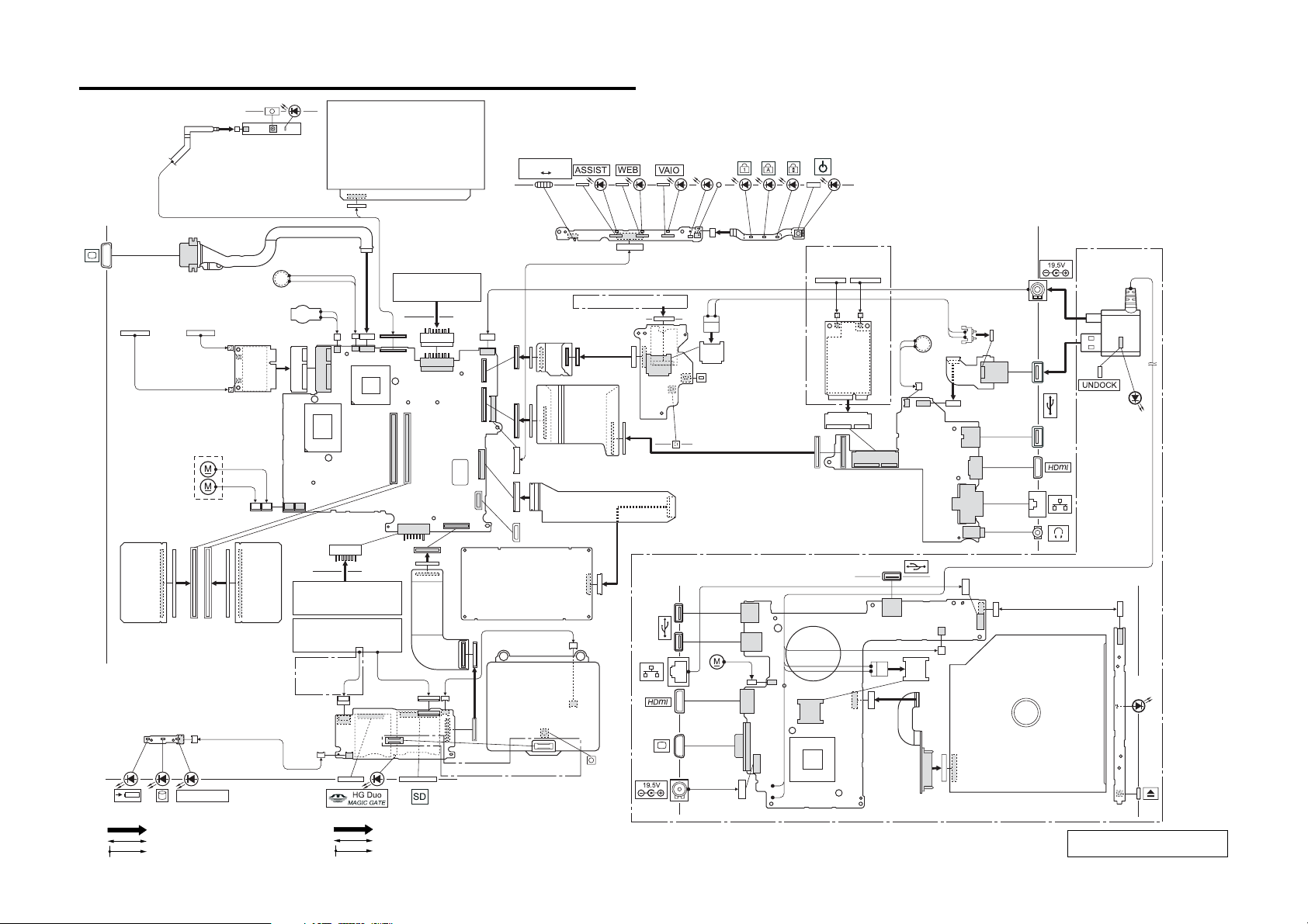
Front
CHAPTER 2.
FRAME HARNESS DIAGRAM
L Side
ANTENNA (WiMAX/WLAN)
SUB MAIN
HD CAMERA
MODULE
HARNESS
SPEAKER L
MN-LI RECHARGEABLE
BATTRY
1
BLK
2
WHT
WLAN/BT COMBO
CARD
FUN UNIT
FPC-225
BATTERY
Bottom
LCD
BATTERY
MBX-236
BOARD
Side A
2nd
Bottom
WIRELESS
OFF ON
Top
FFC (MBX236-SWX354)
FPC-222
N.C.
SSD
HARNESS DC JACK
WAN Model
Rear
FPC-221
FPC-224
MIC
SWX-354
BOARD
Side A
SIM CARD
N.C.
IFX-581
BOARD
Side A
BATTERY
OFF BUTTON
Bottom
Docking Station Model
L Side
HARNESS (RJ-45)
FPC-232
WAN Model
WWAN ANTENNA
MAIN AUX
BLK
GRY
MINI
CARD
Rear
SPEAKER R
IFX-576
BOARD
Side A
JUMPER CABLE
WITH OE MODULE
FPC-226
FFC (IFX578-LEX98)
R Side
DOCKING
CONNECTOR
IN USE
R Side
Front
MM-18
BOARD
Side A
LEX-97
BOARD
Side A
FFC
(IFX577-LEX97)
WIRELESS
From board to connector (direct connection)
Harness (connector at both end)
Harness (soldered at one end)
MM-19
BOARD
Side A
KEYBOARD
UNIT
BACK LIGHT
KB Model
IFX-577
BOARD
Side A
FPC-223
FP Model
ၮ᧼߆ࠄࠦࡀࠢ࠲߳㧔࠳ࠗࠢ࠻ធ⛯㧕
ࡂࡀࠬ㧔┵߇ࠦࡀࠢ࠲ઃ߈㧕
ࡂࡀࠬ㧔৻ᣇ߇ඨ↰ઃߌ㧕
FFC (IFX577-TP)
TOUCH PAD
FINGER PRINT
SENSOR
BUTTON
2-1
(END)
FUN
UNIT
HARNESS
(DC JACK)
IFX-578
BOARD
Side A
FPC-229
ODD
LEX-98 BOARD
Side A
POWER
LAMP
Sony Confidential
VPCZ2 Series (9-890-851-XX)
 Loading...