

Page 1

1.MS-1-D.1
Chapter 1. Disassembly & Assembly Guide
1-3. Disassembly & Assembly
- Main Section -
MS-1 Main Section Disassembly
Confidential
T Series
Page 2
1.MS-1-D.2
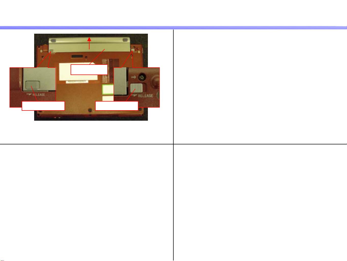
Battery Pack
1)
Remove the Battery Pack while moving the Battery Lock (L)
and the Battery Lock (R) to the RELEASE side.
Confidential
Battery Pack
Battery Lock (L)Battery Lock (R)
T Series
Page 3

1.MS-1-D.3
Cover (L), Cover (R)
Confidential
1) 2)
Remove the nine screws from the Bottom.
Screw: Red-B7 / Blue-B8
3)
Remark
Cover (HL)
Remove the Cover (HL) in the direction of t he arrow whil e
outspreading its both sides and disengage the detent (two places).
Cover (HR)
Position of the detent
Raise the Cover (HR) vertically, and remove it.
T Series
Page 4

1.MS-1-D.4
Keyboard -1
Confidential
1)
3)
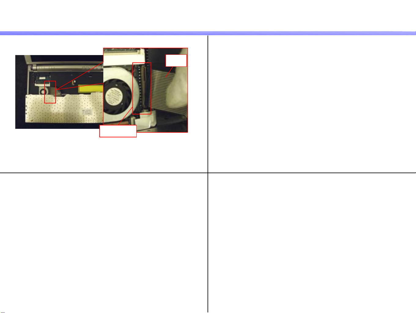
Keyboard
Disengage the detent (two places) and release the Keyboard.
*Push the detent with the bamboo spatula and disengage it.
Keyboard
FPC
Remark
When the Keyboard can not be removed, insert the bamboo skewer
from the back into the screw holes (three places) and release the keyboard.
Back
4)
Cushion
Slide the Keyboard in the direction of the arrow, disengage the detent
(four places) and turn down the front side.
*The FPC is connected to the rear.
Peel off the Cushion.
T Series
Page 5
1.MS-1-D.5
Keyboard -2
5)
Confidential
FPC
Connector
Disconnect the FPC.
*Raise the connector and release the lock.
T Series
Page 6

1.MS-1-D.6
Palmrest -1
Confidential
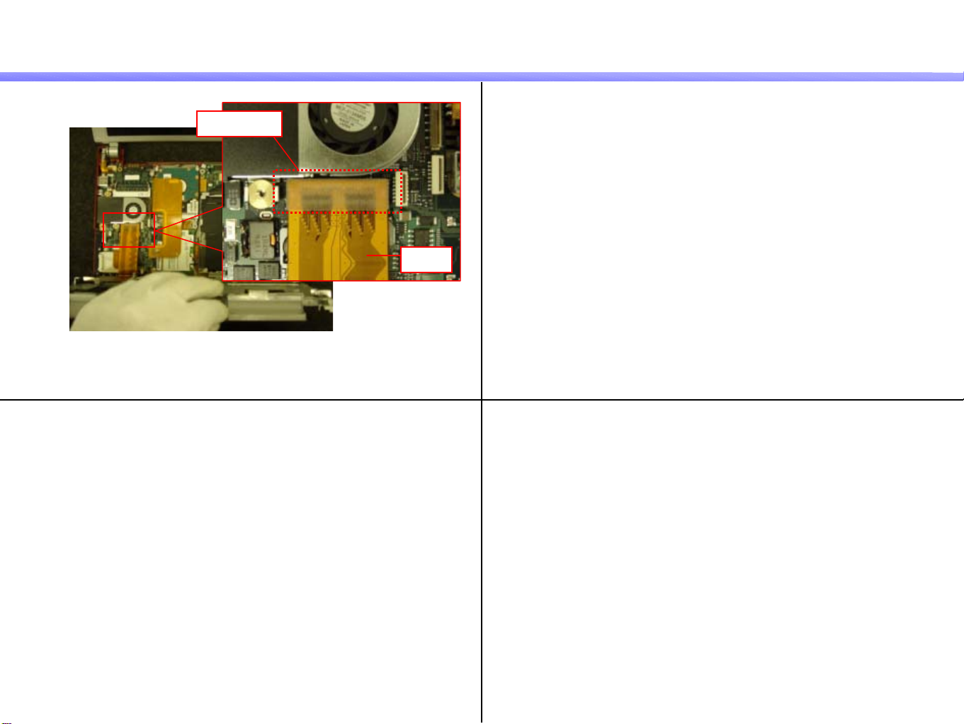
1) 2)
Remove the three screws. Pull out the FFC (three places) vertically.
Screw: B7
3)
FFC
FFC
Remark
Palmrest
Pull the Palmrest toward the front, and raise the Palmrest
to the front side while disengaging the detent (two places).
*The detent is engaged toward the outside.
Position of the detent
T Series
Page 7
1.MS-1-D.7
Palmrest -2
5)
Confidential
Connector
FPC
Disconnect the FPC.
*Disconnect the connector vertically.
T Series
Page 8
1.MS-1-D.8
Confidential
1)
3)
HDD
Hi Type
Peel off the Cushion (one place).
2)
Screw: B10
Cushion
Remove the two screws.
FPC
Disconnect the FPC.
HDD
Remove the HDD.
T Series
Page 9
1.MS-1-D.9
Confidential
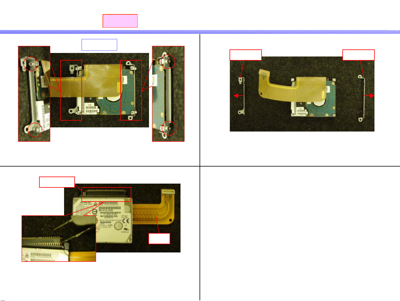
Parts of the HDD
1)
3)
Connector
Hi Type
Screw: B3
Remove the four screws.
2)
Bracket
Bracket
Remove the Bracket (two places).
FPC
Disconnect the FPC.
*Use the tweezers and disconnect the connector portion little by little.
* Be careful not to bend the pins.
T Series
Page 10

1.MS-1-D.10
Confidential
HDD -1
1)
3)
To Type
Peel off the Cushion.
2)
Screw: B10
Cushion
Remove the two screws.
4)
Connector
Bracket (HDD)
Remove the Bracket (HDD).
FPC
Disconnect the FPC.
*Hold the connector and disconnect it vertically.
T Series
Page 11

1.MS-1-D.11
Confidential
HDD -2
5)
To Type
HDD
Remove the HDD.
T Series
Page 12

1.MS-1-D.12
Confidential
Parts of the HDD
1) 2)
Cushion (HDD)
Remove the Cushion (HDD) (four pl ac e s).
To Type
FPC
Connector
Disconnect the FPC.
*Use the tweezers and disconnect the connector portion little by little.
* Be careful not to bend the pins.
T Series
Page 13

1.MS-1-D.13
Memory
Confidential
1)
Remark
2
Memory is installed only in the following these models.
1st --- T90S, T90PS, T160P,T170P
1
Tab
1
Memory
Outspread the tabs (arrow 1) and pull out the Memory
obliquely upward (arrow 2).
T Series
Page 14

1.MS-1-D.14
Wireless LAN Card
Confidential
1)
Wireless LAN Card
Tab
1
1
Outspread the tabs (arrow 1), and pull out the Wireless LAN Card
obliquely upward (in the direction of the arrow 2).
2
T Series
Page 15

1.MS-1-D.15
Optical Disc Drive, CNX-270 Board -1
Confidential
1)
3)
Peel off the Cushion.
CNX Board
2)
Screw: B10
Cushion
Remove the one screw.
4)
Hole
FPC
Escutcheon (Front)
Remove the CNX Board from the Escutcheon (Front)
and disconnect the FPC.
*Pull out it in the direction of the arrow.
Tray
Insert a thin tool into the hole of the Bezel and pull out the Tray.
T Series
Page 16

1.MS-1-D.16
Optical Disc Drive, CNX-270 Board -2
Confidential
5)
7)
Remove the five screws.
6)
Screw: B11
Connector
Disconnect the connector and remove the Optical Disc Drive.
Harness
Disconnect the Harness and remove the CNX Board.
Side B
T Series
Page 17

1.MS-1-D.17
CNX-273 Board -1
Confidential
1) 2)
Remove the one screw.
* The screw secures the CNX Board together with the lug terminal.
Screw: B10
3) 4)
Harness
Tape (Harness)
Peel off the Tape (Harness).
Convex
FPC
Harness
Disconnect the Harness (three places) and the FPC (one place).
Sheet
Hole
Remove the convex portion of the Sheet from the hole.
T Series
Page 18

1.MS-1-D.18
CNX-273 Board -2
Confidential
5)
7)
Tape (Harness)
Peel off the Tape (Harness) (two places).
CNX Board
6)
Sheet
Peel off the Sheet.
8)
Kapton Tape
Peel off the Kapton Tape and remove the CNX Board.
*There is the Modem Card on the rear.
Harness
Disconnect the Harness.
T Series
Page 19

1.MS-1-D.19
Modem Card -1
Confidential
1)
Remark
Nut
Cushion
Remove the Cushion .
2)
3)
Screw: B9
Side B
Remove the one screw.
Side B
Side A
Remove the screw while securing the Nut of the side A
with the 4 mm socket wrench.
Modem Card
Connector
Disconnect the Modem Card.
*There is the connector on the rear.
T Series
Page 20

1.MS-1-D.20
Modem Card -2
Remark
The Stand is installed under the Modem Card.
Confidential
T Series
Page 21

1.MS-1-D.21
LCD Section -1
Confidential
1)
3)
Screw: B6
Remove the one screw.
* The screw secures the lug terminal.
2)
Harness (LCD)
Cover (L)
Pull out the Harness (LCD) from under the Cover (L).
Remark
Cover (L)
Cover (L) Cover (R)
Remove the Cover (L) and the Cover (R) in the direction of the arrow
while disengaging the detent (each one place).
Cover (R)
Position of the detent
T Series
Page 22

1.MS-1-D.22
LCD Section -2
Confidential
4)
Harness (LCD)
Disconnect the Harness (LCD).
5)
LCD
Screw: B10
Remove the two screws and the LCD.
T Series
Page 23

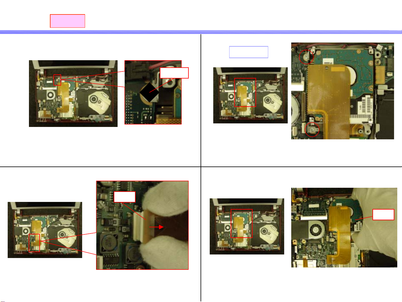
1.MS-1-D.23
Mother Board -1
Confidential
1) 2)
Cover
Remove the two screws and the Cover.
Screw: B10
3) 4)
Screw: Red-B10 / Blue-B11
Cushion
Peel off the Cushion.
Remove the three screws.
FPC
Pull out the FPC (two places) vertically.
T Series
Page 24

1.MS-1-D.24
Mother Board -2
5)
Escutcheon (L)
Remove the Mother Board.
*The connector portion is engaged with the Escutcheon (L).
Confidential
Mother Board
T Series
Page 25

1.MS-1-D.25
Escutcheon (Front), CNX-274 Board
Confidential
1)
3)
Peel off the Sheet (one place).
Screw: B11
Sheet
2)
Peel off the Kapton Tape (one place) and Tape(Harness) (three places).
KaptonTape
Tape (Harness)
4)
CNX Board
Escutcheon (Front)
Remove the one screw and the Escutcheon (Front).
Remove the CNX Board.
T Series
Page 26

1.MS-1-D.26
Parts of the Escutcheon (Front)
Confidential
1)
3)
Screw: B1
Remove the one screw on the both side in the right and the left.
Speaker
2)
Bracket
Remove the Bracket (two places) while disenga gi n g th e
detent (each one place).
Remove the Speaker (two places).
T Series
Page 27

1.MS-1-D.27
Escutcheon (L), Connector (VGA)
Confidential
1)
3)
Peel off the Gasket (one place).
2)
Gasket
Escutcheon (L)
Remove the Escutcheon (L).
Connector (VGA)
Remove the Connector (VGA).
T Series
Page 28

1.MS-1-D.28
Parts of the Connector (VGA)
Confidential
1)
2)
Screw: B5
Bracket
Remove the Bracket.Remove the two screws.
T Series
Page 29

1.MS-1-D.29
Parts of the Housing (Bottom) -1
Confidential
1)
Harness
Adhesive Tape
Remove the Harness (two places).
*The adhesive tapes are attached to the rear.
2)
3) 4)
Plate
Remove the Plate.
DC Jack
Remove the Escutcheon (R).
Escutcheon (R)
Remove the DC Jack while sliding it toward the front side.
T Series
Page 30

1.MS-1-D.30
Parts of the Housing (Bottom) -2
Confidential
5)
Sheet
Remove the Sheet.
Remark
Sheet
Sheet
Cushion
Spacer
Sheet
The Sheet (three places), Gasket (one place), Cushion (one place) and
Spacer (one place) are attached to the Housing (Bottom).
Gasket
T Series
Page 31

Confidential
Update History
Date Contents Version No.
- - -
[ADD]---Addition [DEL]---Deletion [CHG]---Change [COR]---Correction [MA]---Model Addition
-
T Series
 Loading...