

Sony PMW-EX1R, VCL-EX0877 Service Manual

SOLID-STATE MEMORY CAMCORDER
PMW-EX1R
WIDE CONVERSION LENS
VCL-EX0877
SERVICE MANUAL
1st Edition

!警告
このマニュアルは,サービス専用です。
お客様が,このマニュアルに記載された設置や保守,点検,修理などを行うと感電や火災,
人身事故につながることがあります。
危険をさけるため,サービストレーニングを受けた技術者のみご使用ください。
! WARNING
This manual is intended for qualifi ed service personnel only.
To reduce the risk of electric shock, fi re or injury, do not perform any servicing other than that
contained in the operating instructions unless you are qualifi ed to do so. Refer all servicing to
qualifi ed service personnel.
! WARNUNG
Die Anleitung ist nur für qualifi ziertes Fachpersonal bestimmt.
Alle Wartungsarbeiten dürfen nur von qualifi ziertem Fachpersonal ausgeführt werden. Um die
Gefahr eines elektrischen Schlages, Feuergefahr und Verletzungen zu vermeiden, sind bei
Wartungsarbeiten strikt die Angaben in der Anleitung zu befolgen. Andere als die angegeben
Wartungsarbeiten dürfen nur von Personen ausgeführt werden, die eine spezielle Befähigung
dazu besitzen.
! AVERTISSEMENT
Ce manual est destiné uniquement aux personnes compétentes en charge de l’entretien. Afi n
de réduire les risques de décharge électrique, d’incendie ou de blessure n’effectuer que les
réparations indiquées dans le mode d’emploi à moins d’être qualifi é pour en effectuer d’autres.
Pour toute réparation faire appel à une personne compétente uniquement.
PMW-EX1R
注意
FÖRSIKTIGHET!
指定以外の電池に交換すると,破裂する危険があります。
必ず指定の電池に交換してください。
使用済みの電池は,国または地域の法令に従って
処理してください。
CAUTION
Danger of explosion if battery is incorrectly replaced.
Replace only with the same or equivalent type recommended by the manufacturer.
When you dispose of the battery, you must obey the
law in the relative area or country.
ATTENTION
Il y a danger d’explosion s’il y a remplacement incor-
rect de la batterie. Remplacer uniquement avec
une batterie du même type ou d’un type équivalent
recommandé par le constructeur.
Lorsque vous mettez la batterie au rebut, vous devez
respecter la législation en vigueur dans le pays ou la
région où vous vous trouvez.
Fara för explosion vid felaktigt placerat batteri.
Byt endast mot samma eller likvärdig typ av batteri,
enligt tillverkarens rekommendationer.
När du kasserar batteriet ska du följa rådande lagar
för regionen eller landet.
PAS PÅ
Fare for eksplosion, hvis batteriet ikke udskiftes
korrekt.
Udskift kun med et batteri af samme eller tilsvarende
type, som er anbefalet af fabrikanten.
Når du bortskaffer batteriet, skal du følge
lovgivningen i det pågældende område eller land.
HUOMIO
Räjähdysvaara, jos akku vaihdetaan virheellisesti.
Vaihda vain samanlaiseen tai vastaavantyyppiseen,
valmistajan suosittelemaan akkuun.
Noudata akun hävittämisessä oman maasi tai
alueesi lakeja.
VORSICHT
Explosionsgefahr bei Verwendung falscher Batterien.
Batterien nur durch den vom Hersteller empfohlenen
oder einen gleichwertigen Typ ersetzen.
Wenn Sie die Batterie entsorgen, müssen Sie die
Gesetze der jeweiligen Region und des jeweiligen
Landes befolgen.
FORSIKTIG
Eksplosjonsfare hvis feil type batteri settes i.
Bytt ut kun med samme type eller tilsvarende
anbefalt av produsenten.
Kasser batteriet i henhold til gjeldende avfallsregler.
PMW-EX1R
1 (P)


Table of Contents
Manual Structure
Purpose of this manual ............................................................ 3 (E)
Related manuals ...................................................................... 3 (E)
1. Service Overview
1-1. External Connectors .................................................. 1-1 (E)
1-1-1. Signal Inputs and Outputs ................................ 1-1 (E)
1-2. Location of the Printed Wiring Boards .....................1-3 (E)
1-3. Circuit Description .................................................... 1-4 (E)
1-4. Service Tools/Measuring Equipment List ............... 1-12 (E)
1-4-1. Service Tools ..................................................1-12 (E)
1-4-2. Measuring Equipment ....................................1-12 (E)
1-5. Firmware Upgrade...................................................1-13 (E)
1-6. Recommended Replacement Parts .......................... 1-14 (E)
1-7. Circuit Protection Part List ...................................... 1-15 (E)
1-7-1. Circuit Protection Element.............................1-15 (E)
1-7-2. Replacing Fuse ............................................... 1-15 (E)
1-8. Note on Service ....................................................... 1-16 (E)
1-8-1. Requirements on Replacement of Boards
or Parts ........................................................... 1-16 (E)
1-8-2. Requirements on Replacement of Lens .........1-16 (E)
1-8-3. Note on Replacement of Parts on
the Board ........................................................ 1-16 (E)
1-8-4. Description of Number Seal on the Prism ..... 1-16 (E)
1-8-5. Memory Backup Battery ................................ 1-17 (E)
1-8-6. Unleaded Solder ............................................. 1-17 (E)
1-9. Connector Location Diagram on Board ..................1-18 (E)
1-10. Connecting/Disconnecting the Flexible
Card Wire ................................................................1-19 (E)
1-11. Replacing the Coaxial Cable with Connector
(Fine Pitch Coaxial Cable) ..........................................1-20 (E)
2. Replacement of Main Parts
2-1. Outline of Replacement Procedures .........................2-1 (E)
2-2. Replacement Procedures ...........................................2-2 (E)
2-2-1. Lithium Battery ............................................... 2-2 (E)
2-2-2. Case (Bottom) L/R and Front Panel
Assembly .........................................................2-2 (E)
2-2-3. Microphone Holder Assembly ........................ 2-4 (E)
2-2-4. EVF Assembly ................................................. 2-4 (E)
2-2-5. Handle Assembly ............................................. 2-5 (E)
2-2-6. DAP-41 Board and AU-326 Board .................. 2-7 (E)
2-2-7. SW-1478 Board................................................2-8 (E)
2-2-8. Inside Panel Assembly/Outside Panel
Assembly .........................................................2-8 (E)
2-2-9. Rear Panel Assembly .....................................2-10 (E)
2-2-10. Express Card Assembly ................................. 2-11 (E)
2-2-11. RE-272 Board and RE-273 Board ................. 2-12 (E)
2-2-12. Battery Case, TX-131 Board .........................2-13 (E)
2-2-13. DPR-311 Board ..............................................2-15 (E)
2-2-14. Case L Assembly............................................ 2-16 (E)
2-2-15. Case R ............................................................2-17 (E)
2-2-16. Prism Assembly .............................................2-18 (E)
2-2-17. ND Filter ........................................................2-18 (E)
2-2-18. Lens Unit........................................................2-19 (E)
2-2-19. DR-644 Board ................................................ 2-19 (E)
2-2-20. LED-491 Board..............................................2-20 (E)
2-2-21. Speaker...........................................................2-20 (E)
2-2-22. KSW-55 Board, HN-361 Board .....................2-21 (E)
2-2-23. Microphone Unit Assembly ........................... 2-22 (E)
2-2-24. Microphone Unit ............................................ 2-23 (E)
2-2-25. DET-52 Board ................................................ 2-24 (E)
2-2-26. 3.5-inch LCD Assembly ................................ 2-25 (E)
2-2-27. Replacing the Parts in the Lens Grip ............. 2-26 (E)
3. SERVICE Menu
3-1. Outline of SERVICE Menu .......................................3-1 (E)
3-1-1. Basic Menu Operations .................................... 3-1 (E)
3-1-2. SERVICE Menu Structure ............................... 3-1 (E)
3-1-3. Displaying the SERVICE Menu ......................3-1 (E)
3-2. SERVICE Menu List .................................................3-2 (E)
3-2-1. MAINTENANCE Menu .................................. 3-2 (E)
3-2-2. RPN CORRECT Menu ....................................3-2 (E)
3-2-3. INFORMATION Menu ................................... 3-3 (E)
3-3. Self-Diagnostic Function...........................................3-4 (E)
3-4. Executing Log Dump ................................................ 3-9 (E)
3-5. List of Error Numbers on the LCD Display ............3-10 (E)
PMW-EX1R
1 (E)

4. Alignment
6. Block Diagrams
4-1. Servicing software “ServiceNavi-EX” ......................4-1 (E)
4-2. Preparation ................................................................ 4-1 (E)
4-2-1. Service Tools and Equipment ..........................4-1 (E)
4-2-2. Connection ....................................................... 4-1 (E)
4-3. MAINTENANCE Menu ........................................... 4-1 (E)
4-3-1. Test Saw Setting ............................................... 4-1 (E)
4-3-2. Executing Auto Black Balance ........................ 4-2 (E)
4-3-3. Black Shading Adjustment...............................4-2 (E)
4-3-4. White Shading Adjustment ..............................4-3 (E)
4-3-5. Flare Adjustment .............................................. 4-5 (E)
4-3-6. Executing Auto FB Adjust ...............................4-6 (E)
4-4. RPN CORRECT Menu .............................................4-8 (E)
4-4-1. Executing Auto Detection ................................ 4-8 (E)
4-4-2. Correction Mode Settings ................................ 4-8 (E)
4-4-3. Channel Setting ................................................ 4-8 (E)
4-4-4. Cursor Setting .................................................. 4-8 (E)
4-4-5. Cursor H Position Setting ................................ 4-9 (E)
4-4-6. Cursor V Position Setting ................................ 4-9 (E)
4-4-7. Operating Cursor Next ..................................... 4-9 (E)
4-4-8. Operating Cursor Prev ..................................... 4-9 (E)
4-4-9. Compensation Level Display ........................... 4-9 (E)
4-4-10. Executing Record ............................................. 4-9 (E)
4-4-11. Executing Delete ............................................ 4-10 (E)
4-4-12. Readout Mode Setting ...................................4-10 (E)
4-4-13. Executing Reset .............................................4-10 (E)
5. Spare Parts
5-1. Notes on Repair Parts ......................................................5-1
5-2. Exploded Views ............................................................... 5-2
5-3. Supplied Accessories ..................................................... 5-18
Overall ............................................................................. 6-2
AU-326 ............................................................................6-3
AXM-42 ...................................................................... 6-3, 8
DAP-41................................................................6-3, 4, 6, 7
HN-356 ................................................................ 6-3, 4, 6, 7
HN-360 ............................................................................6-3
HN-361 ............................................................................6-3
KSW-55 .......................................................................6-3, 8
MA-183 ........................................................................... 6-3
SW-1478 ...................................................................... 6-3, 4
SWC-50 ........................................................................... 6-3
BI-202.............................................................................. 6-4
BI-203.............................................................................. 6-4
BI-204.............................................................................. 6-4
DPR-311 .............................................................. 6-4, 5, 6, 7
CN-3273 .................................................................... 6-5, 11
EC-68 .............................................................................. 6-5
DET-52 ............................................................................ 6-8
DR-644 ............................................................................ 6-8
HN-363 ............................................................................ 6-8
RM-224 ........................................................................... 6-8
CN-3258 .......................................................................... 6-9
DC-152 ............................................................................ 6-9
RE-272 ............................................................................ 6-9
CN-3259 ........................................................................ 6-10
RE-273 .......................................................................... 6-10
ASW-68 ......................................................................... 6-11
LED-491 ........................................................................ 6-11
LED-494 ........................................................................ 6-11
SW-1484 ........................................................................ 6-11
TX-131 .......................................................................... 6-12
VIF-46 ........................................................................... 6-12
2 (E)
7. Schematic Diagrams
Frame Wiring...................................................................7-1
PMW-EX1R

Purpose of this manual
Related manuals
Manual Structure
The service manual is intended for use by trained system and service engineers, and
provides the information of maintenance and detailed service.
The following manuals are available in this model.
If this manual is required, please contact your local Sony Sales Offi ce/Service Center.
. Operating Instructions (Supplied with unit)
This manual is necessary for application and operation of this unit.
. “Semiconductor Pin Assignments” CD-ROM (Available on request)
This “Semiconductor Pin Assignments” CD-ROM allows you to search for
semiconductors used in Broadcast and Professional equipment.
Part number: 9-968-546-06
PMW-EX1R
3 (E)

Section 1
Service Overview
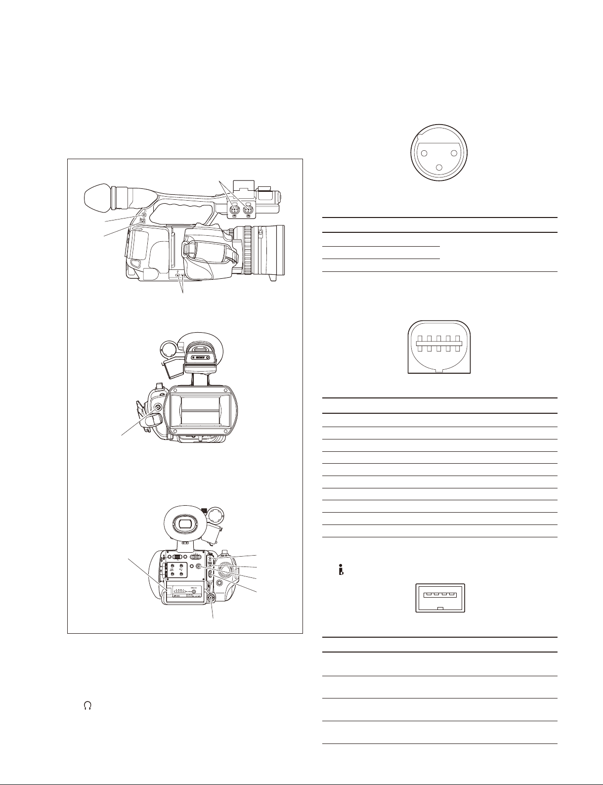
1-1. External Connectors
1-1-1. Signal Inputs and Outputs
SIDE VIEW
FRONT VIEW
3 AUDIO IN CH-1, CH-2: XLR (3P, Female)
2
_ EXT VIEW _
1
3
(0 dBu = 0.775 V rms)
No. Signal I/O Specifi cations
1 MIC/LINE (G) _ _65 dBu to _8 dBu
2 MIC/LINE (H) IN +4 dBu, selectable
3 MIC/LINE (C) IN High impedance, Balanced
4 A/V OUT: Multiconnector (10P)
10
9
_ EXT VIEW _
2
1
REAR VIEW
CANCEL
SEL/SET
PICTURE
PROFILE
AUTO
INTMIC
CH-1
EXT
MANUAL
AUTO
INTMIC
CH-2
MANUAL
EXT
PMW-EX1R
EXPANDED
REC
REVIEW
FOCUS
DC IN
START/
STOP
RELEASE
OFF
CAMERA
MEDIA
MENU
1 SDI OUT: BNC type
SDI output signal
2 (HEADPHONES): Stereo mini jack
Sound monitor, monaural/stereo selectable
_20.5 dBu (Reference level 16 Z loaded)
No. Signal I/O Specifi cations
1 LINE_MONI1_L (A/V) O LINE OUT (L)
2 LANC_SIG _ NC
3 S_GND _ GND
4 LANC_DC _ NC
5 S-C O NC
6 LINE_MONI2_R (A/V) O LINE OUT (R)
7 AV_SW I
8 VIDEO/AUDIO_GND _ GND
9 VIDEO O Composite OUT
10 S-Y O NC
5 HDV/DV: i.LINK connector (IEEE1394, S400) (4P)
14
_ EXT VIEW _
No. Signal I/O Specifi cations
1 TPB_ I/O Strobe on receive, data on
transmit B (_)
2 TPB+ I/O Strobe on receive, data on
transmit B (+)
3 TPA_ I/O Data on receive, strobe on
transmit A (_)
4 TPA+ I/O Data on receive, strobe on
transmit A (+)
PMW-EX1R
1-1 (E)
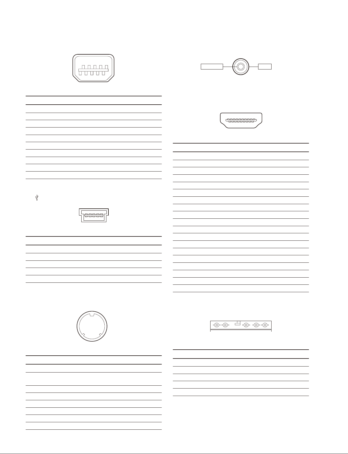
6 COMPONENT OUT: Mini D terminal (10P)
9 DC IN: 2P (DC JACK TYPE 4)
19
210
_ EXT VIEW _
No. Signal I/O Specifi cations
1 Y O COMPONENT (Y)
2 YGND _ Y GND
3 PB O COMPONENT (Pb)
4 PBPR_GND _ PBPR GND
5 PR O COMPONENT (Pr)
6 NC _
7 NC _
8 NC _
9 SW_GND _
10 SW I
7 (USB): Mini-B connector (5P)
15
_ EXT VIEW _
No. Signal I/O Specifi cations
1 VCC _ USB Vcc
2 D_ I/O USB_
3 D+ I/O USB+
4 ID _ NC
5 GND _ Ground
GNDEXT DC
_ EXT VIEW _
0 HDMI OUT: (19P)
19 1
18 2
_ EXT VIEW _
No. Signal I/O
1 TMDS_DATA2+ O
2 TMDS_DATA2_SHIELD _
3 TMDS_DATA2_ O
4 TMDS_DATA1+ O
5 TMDS_DATA1_SHIELD _
6 TMDS_DATA1_ O
7 TMDS_DATA0+ O
8 TMDS_DATA0_SHIELD _
9 TMDS_DATA0_ O
10 TMDS_CLOCK+ O
11 TMDS_CLOCK_SHIELD _
12 TMDS_CLOCK_ O
13 CEC (N.C.) _
14 RESERVED (N.C.) _
15 SCL O
16 SDA I/O
17 DDC/CEC_GND _
18 +5V_POWER O
19 HPD I
8 LENS REMOTE: (8P FEMALE)
18
2
3
4
7
6
5
_ EXT VIEW _
No. Signal I/O Specifi cations
1 COMMON_V O GND
2 ZOOM I GND: WIDE 1.66V: STOP
3.33V: TELE
3 COMMON+V O 3.33V
4 COMMON I 1.66V
5 REC I GND: ON OPEN: OFF
6 RET I GND: ON OPEN: OFF
7 SW COMMON O GND
8 FRAME GND _
1-2 (E)
!- Battery: (5P)
12
_ EXT VIEW _
No. Signal I/O Specifi cations
1 BATT (+) _ +11 to +17 V dc
2 BAT_SCL O
3 BAT_SDA I/O
4 BATT_ID_DATA I
5 BATT (_) _
345
PMW-EX1R
1-2. Location of the Printed Wiring Boards
1 ASW-68 board
2 AU-326 board
3 AXM-42 board
4 BI-202 board
5 BI-203 board
6 BI-204 board
7 CN-3258 board
8 CN-3259 board
9 CN-3273 board
0 DAP-41 board
!- DC-152 board
!= DET-52 board
![ DPR-311 board
!] DR-644 board
!\ EC-68 board
!; HN-356 board
!' HN-360 board
!, HN-361 board
!. HN-363 board
@/ IF-1127 board
@- KSW-55 board
@= LED-491 board
@[ LED-494 board
@] MA-183 board
@\ RE-272 board
@; RE-273 board
@' RM-224 board
@, SW-1478 board
@. SW-1484 board
#/ SWC-50 board
#- TX-131 board
#= VIF-46 board
PMW-EX1R
1-3 (E)

1-3. Circuit Description
1. CMOS Block System
BI-202/203/204 Board
The BI-202, BI-203 and BI-204 boards are the rigid fl exible boards connecting the CMOS image sensors (IC1) to the
DPR-311 board.
The CMOS image sensor receives the three primary colors of R, G and B that are separated from the incoming light by the
prism. The CMOS image sensor converts the incoming primary color to electric signal. The built-in 12-bit column A/D
converters then convert the R, G and B analog video signals to the digital video signals respectively.
The electronic shutter, analog gain amplifi er and black level clamp functions are also provided in the above boards.
The BI-202 board is for the R-channel signal, the BI-203 board is for the G-channel signal and the BI-204 board is for the
B-channel signal.
The CMOS image sensor receives the sync signal and the serial communication signal from the DPR-311 board. The 12-bit
digital video signals that are supplied from the CMOS image sensors pass through the EMI fi lters (FL1 to FL4) and are
input to the DPR-311 board.
Various decoupling capacitors and the damping resistors are also mounted in the above boards.
IC3 of the BI-203 board is a temperature sensor that sends the temperature data to the CAMERA MICON (camera
μ-processor: IC500) on the DPR-311 board via I2C bus.
2. Camera Block System
DPR-311 Board
The DPR-311 board consists of the Camera Signal Processor IC (IC200) and the CAMERA MICON (camera μ-processor:
IC500) whereas the Camera Signal Processor IC (IC200) performs various processing on the digital video signal supplied
from the CMOS image sensor, and the CAMERA MICON (IC500) performs control of IC200 and other various controls
such as control of the CMOS image sensor and of lens. And the output digital video (Y/C) signal is sent to the next circuit
the video (baseband video) signal processing circuit.
The 12-bit digital video (RGB) signals supplied from the CMOS block (BI-202, BI-203 and BI-204 boards) fi rst enter the
camera signal processor IC (IC200). In the camera signal processor IC (IC200), average value, peak value of the RGB
digital video signals that are required for the following AUTO operations of the camera are detected.
The detected signals are sent to the CAMERA MICON (camera μ-processor: IC500).
. Auto white balance
. Auto black balance
. Auto focus
. Auto iris
. Auto knee
The digital video signal from the CMOS image sensor enters fi rst the selector circuit selecting either the digital video signal
from the CMOS image sensor or the internal TEST signal. The output video signal from the selector enters the compensation circuits consisting of the CMOS imager-related compensation circuit and the lens-related compensation circuit. The
video signal then receives the white balance processing, and the matrix signal and the detail signal are added to the video
signal. The video signal then receives the pedestal control, knee compensation, gamma correction and white/black clip
processing. The video signal fi nally enters the baseband processing IC (IC600).
The pixel number conversion processing from 1920/1080 to 1440/1080 or 1280/720 is also performed inside IC200.
1-4 (E)
PMW-EX1R

The CAMERA MICON (camera μ-processor: IC500) performs the overall control over the entire camera system and is controlled by the camera system controller (IC2900).
Peripheral ICs of the CAMERA MICON (camera μ-processor: IC500) are FLAH ROM (IC413) and SDRAM (IC414).
3. Video Signal System
DPR-311 Board
The digital video (Y/C) signal output from the camera signal processor IC (IC200) enters the baseband processing IC
(IC600).
The baseband processing IC (IC600) performs the overall baseband processing of video and audio signals with a single chip
IC containing the various scaler functions (supporting the multiple format outputs), various OSD functions, PLL function
(54 MHz → 74 MHz) and CPU.
The baseband processing IC (IC600) provides the following outputs:
. HD/SD Component (digital): To TX-131 board
. HD/SD Component (analog): To TX-131 board
. Composite (analog): To TX-131 board
. LCD signal (digital): To LCD module
. EVF signal (analog): To DR-644 board
The input/output signals of the baseband processing IC (IC600) are the following signals:
. MPEG encoder/decoder I/F signal (digital): To IC1500
. Audio I/F signal (digital): To IC1300
Peripheral circuits of the baseband processing IC (IC600) are the master clock 54 MHz VCXO (X800) control circuit
(IC803, IC804, IC806, IC807, IC808) and the Mobile DDR SDRAM memory (IC1100, IC1101).
Peripheral circuits of the built-in CPU are FLASH ROM (IC1003) and SDRAM (IC1000).
The baseband processing IC (IC600) is controlled by the system controller (IC2900). The LCD driver IC, the EVF driver
IC, SDI Co-pro, the audio system and the power save control of the output systems are controlled by the built-in CPU
inside IC600.
4. Media Recording and Playback
DPR-311 Board
Output from the baseband processing IC (IC600) is input into the MPEG encoder/decoder (IC1500).
The MPEG encoder/decoder (IC1500) is the single-chip MPEG Codec IC that encodes and decodes both the high-quality
HD video signal and audio signal in real-time. It has various interfaces with signals such as MPEG video, video input/
output, MPEG audio, audio input/output, bit stream input/output, and interface with the host.
IC1500 output is then input into LSI (IC1600) for AVIT signal processing.
LSI (IC1600) for AVIT signal processing contains the built-in CPU and has interfaces for DDR2 SDRAM memory (IC1800,
IC1801), PCI bus, PCI-Express bus, I/O for IC1500, and serial communication with system controller (IC2900).
IC1600 is also connected to the NOR-type Flash ROM (IC1901) to read the CPU program in the IC1600 during initial startup.
LSI (IC1600) for AVIT signal processing is controlled by the system controller (IC2900), in the same way as other main
devices, and provides the following types of functions: video/audio stream control, access to the SxS memory card, mass
storage operations when connected to USB and HDV device controls when connected to i-LINK.
Explanation of peripheral devices
<SxS memory card slot>
Two memory card slot boards (EC-68) are connected to the dual channel PCI-Express signals coming from IC1600 through
a 0.4 mm pitch, 30-pin fi ne coaxial cables connected to CN2400 and CN2401.
Furthermore, dual channel USB host signals output from USB host controller (IC2300) are connect to the EC-68 board
through fi ne coaxial cables just as with the PCI-Express signals.
IC2300 is controlled by PCI bus from IC1600.
PMW-EX1R
1-5 (E)

<USB device controller>
USB device signal output from USB device controller (IC2000) is connected to output board (DAP-41) through the bothsided fl exible board (HN-356) from CN3302 connector, and then it is connected to USB Mini-B connector (CN106) on the
DAP-41 board.
IC2000 is controlled by the dedicated bus from IC1600.
If there is no USB connection, the power supply for IC2000 drops off.
<i-Link controller>
The i-Link signal output from the i-Link controller (IC2200) is connected to the 4-pin i-Link connector (CN3) on the
CN-3273 board passing through the both-sided fl exible board (CN-3273) from the CN3400 connector.
IC2200 is controlled by the PCI bus from IC1600.
5. Audio system
This overview explains the audio system according to the audio block diagram shown in Fig. 1.
MA-183 Board
The MA-183 board contains a built-in microphone unit. The MA-183 board amplifi es the audio signal with the microphone bias
power supply and head amplifi er (Q5, Q7, and Q9, and Q6, Q8, and Q10). It provides the balanced output for the audio signal.
AXM-42 Board
The AXM-42 board is a connector board on which XLR (3-pin) connector for external LINE/MIC input and the [LINE/
MIC/MIC +48V] input selection switch for two channels are mounted on this connector board.
KSW-55 Board
This board performs the read and tally controls for the switch on the handle. The audio signal block relays the audio signal
between the MA-183 board and AXM-42 board.
HN-360/HN-361 Flexible board
This board relays the audio signal between the KSW-55 board and the AU-326 board.
AU-326 Board (Audio block)
This board controls the analog audio input signal processing, as well as microphone +48 V power supply and serial signal.
. Audio signal from the built-in microphone on the MA-183 board is input to the balanced input amplifi er IC200 and IC201
of this board. Output of the balanced amplifi er is connected to the analog switch (IC208, IC209) for switching between
[INT/EXT].
. The DC-DC converter (IC100, Q100) for microphone power +48 V is built-in, and when EXT MIC +48 V is going to be
supplied, the EXT MIC +48 V is supplied by the switch (Q200, Q201, Q202 and Q203).
. The audio input signals from MIC and LINE are input to a common circuit that receives both of the MIC input level (_20
dBu to _65 dBu) and the LINE input level (+4 dBu). The input attenuator is inserted in the circuit switch (Q212, Q213,
Q214, Q215 and Q216 to Q219) as required. This audio input signal is received by the balanced input amplifi er (IC202,
IC203) that performs amplifi cation of 0/+12 dB and switching (Q224, Q225, Q226, Q227) in accordance with the level
that is set by INPUT TRIM. After that, the audio signal is connected to the [INT/EXT] switch (IC208, IC209).
. The [INT/EXT] switch (IC208, IC209) performs not only the INT/EXT switching but also performs the input channel
mode selection [CH1/ (CH1/CH2)].
. SEL (IC204, IC205)/AMP (IC206, IC207) are a signal selector and buffer amplifi er to perform AGC link.
DAP-41 Board (Audio block)
The DAP-41 board is comprised of two pieces of the Audio Codec IC and the IC202, IC203.
(RTC is also built on this board, but the explanation has been omitted here.)
1-6 (E)
PMW-EX1R

. Audio Codec (IC202, IC203)
The analog audio signal from the AU-326 board is connected to IC202 and IC203 that are the Audio Codec (PGA, ADC,
2
DSP, Digital IF, headphones amplifi er, speaker amplifi er are built on one chip and the parameters are set with I
C).
The analog signal after level adjustment by the Input TRIM (PGA) is converted to the digital signal with the ADC.
The digital signal receives the [Wind Filter] (on/off) processing of the Audio Level control, AGC Limiter and Internal
mic from the DSP. After the audio signal receives these processing, the digital signal is output for audio recording.
Playback output (including EE) is the digital signal that is connected to Audio Codec where it is converted to the analog
signal with DAC and output to the ASW-68 board.
Furthermore, the audio signal that is processed for audio monitoring in the ASW-68 board is connected to the headphones
amplifi er and speaker amplifi er through the monitor level control from the IN2LP input and IN2RP input of IC202.
From the DPR-311 board, BEEP (IC600) is level-controlled internally by IN2LN (IC202), and output to the speaker HP.
. FPGA (IC1300) on the DPR-311 Board
The digital signal output signal is supplied to the Display Block (Base band) from the Audio Codec. FPGA (IC1300) also
receives the playback output signal from the Display Block.
The playback system selects CH1/CH2 or CH3/CH4, connects EE, and connects TEST TONE from the Display Block
depending on the data.
Furthermore, FPGA divides the clock signal that is supplied from the Display Block to Audio Codec on the DAP-41 board.
MA-183
INT MIC1
with
HEAD AMP
+10dB
INT MIC2
with
HEAD AMP
+10dB
MIC/LINE
1
(XLR)
MIC/LINE
2
(XLR)
AXM-42
AV Monitor
Out 1
(Line Out1)
AV Monitor
Out 2
(Line Out2)
VIF-46
HP Out
(PHONE
MINI)
SPEAKER
KSW-55
LED-491
HN-361
DPR-311
WIND FILTER1
NH-360
FIL
ATT
+48V /MIC / LINE -1
WIND FILTER2
FIL
ATT
+48V /MIC / LINE -2
AU-326
MUTE
MUTE
MUTE
MUTE
PWR or
DET
ASW-68
+48V
+48V
IC204 (1/2)
IC204 (2/2)
COPY1to2, LINK2to1, LINK1to2
BAL
AMP
INT/EXT 1
BAL
AMP
IC200
IC203
BAL
AMP
0/12dB-1
Control
with PGA
IC202
BAL
AMP
INT/EXT 2
0/12dB-2
Control
with PGA
AMP
AMP
MUTE
MONI1-1,2-1,
MONI2-2,2-1
INT/EXT1,INT/EXT2
MIC/LINE/+48V-1,
MIC/LINE/+48V-2,
WIND FILTER1,
WIND FILTER2
COPY1to 2
SEL/
MIX1
IC200,
IC202 (1/2)
MONI 1-1
MONI 2-1
SEL/
IC201,
MIX2
IC202 (2/2)
MONI2-2
MONI1-2
IC203, 205
GPIO
SEL/
MIX1
LINK 2 1
SEL/
MIX2
LINK 1 2
CN-3273
PGA
GAIN
PGA
GAIN
PGA
GAIN
PGA
GAIN
DAP-41
A/D
A/D
AMP
AMP
AMP
MONITOR LEVEL
IC205,206,207,208
IC202(1/2)
AGC/
FIL LVL
LIM
IC203
AGC/
FIL
IC202 IC203
LIM
IC202(2/2)
+
IC201
I2C MPX
(DEVICE CONTROL)
LVL
D/A
MIX
AMP
GPIO
IN2LP(L)
IN2RP(R)
IN2LN
DIGITAL
AUDIO IF
DIGITAL
AUDIO IF
I2C
CONTROL
(T-one)
IC600
FPGA
Digital Audio 1
CLOCK DIV
(1fs,64fs,256fs)
Digital Audio 2
Digital Audio
1/2 , 3/4
CLOCK DIV
(1fs,64fs,256fs)
IC1300
LINE 3/4
DPR-311
IC600
BEEP
(T-one)
IC600
CONTROL
I2C
(T-one)
PMW-EX1R
Fig. 1. Audio block diagram
1-7 (E)

. Serial control
2
The I
C control signal from Display Block (Base band) is converted into GPI, and performs switching
such as [INT/EXT], [LINE/MIC/MIC+48], [CH1/ (CH/CH)], and AGC [Linked/Separated] for CH1
and CH2.
2
The I
C control from Display Block (Base band) selects either IC202 or IC203 for the target with I2C
MPX (IC201) and sets the register of IC202 or IC203.
CN-3273 Flexible board
It relays the audio signal from the DPR-311 board to the ASW-68 board.
ASW-68 Board (Audio block)
. Analog output from the DAP-41 board Audio Codec is buffered by IC204 and is output to the A/V
connector after passing through the audio MUTE control.
. Analog output from Audio Codec on the DAP-41 board re-enters into the IN2LP input and IN2RP input
of the DAP-41 board Audio Codec after passing through the monitor selector/mixer (IC200, IC201,
IC202), and becomes the monitor signal.
. Serial control
2
I
C control signal from Display Block (Base band) is output at GPI, and performs the switching be-
tween MONITOR [CH1/CH2] / [CH1+CH2] / [CH1] / [CH2] for CH1 and CH2 respectively.
VIF-46 Board (Audio block)
The audio output from the ASW-68 board is connected to A/V multi-connector and connector board.
LED-491 Board (Audio block)
The headphones output signal is connected to the headphones jack (CN3) of the LED-491 board, and the
speaker output signal is connected to the speaker connector (CN2).
The headphones output is muted by the MUTE (Q2, Q3).
Switch/Volume control (Audio controller block)
Operation panel functions relating to audio signal are built into the following blocks.
ASW-68 Board (Audio block)
For CH1 and CH2, the switches [INT/EXT] and [AUTO/MANUAL] are connected to PIO of CPU
(IC301), and the volume control [AUDIO LEVEL] is connected to ADC of CPU (IC301).
KSW-55 Board (Audio block)
The switch [LINE/MIC/MIC+48] on the AXM-42 board is connected to PIO of CPU (IC100) for CH1
and CH2 respectively. The switch [MONITOR (AUDIO) +/_] that is common to CH1 and CH2 is connected to PIO of CPU (IC100).
6. System Control
DPR-311 Board
The 32-bit RISC CPU (ARM) with ARM core is built-in as the system controller (IC2900).
It has the peripheral interface functions of SDRAM, USB, SCI, and I2C. It operates on a 27 MHz clock
(X2900). FLASH ROM (IC2908), SDRAM (IC2909), and EEPROM (IC3205) are mounted as the peripheral ICs.
It performs the system control through serial communication with IC500 of the camera block system,
IC600 of the video signal system, and IC1600 of the media recording/playback system.
1-8 (E)
PMW-EX1R

Main functions of the system controller and peripherals
(1) Reading operation switch information
2
Reading the switch information and the LED control are performed by I
C bus communication with each
sub-microprocessor.
. Handle switch: IC100 on the KSW-55 board
. Inside panel switch: IC200 on the SWC-50 board
. Rear panel switch: IC301 on the ASW-68 board
. Power supply switch: IC1001 on the RE-273 board
(2) Watch IC (RTC) control
The watch IC (IC100) is built onto the DAP-41 board.
The watch IC (IC100) is backed up by a lithium coin battery, and the current time is read or set via IC200
on the SWC-50 board.
(3) Infrared remote control demodulation
The RM-224 board has an IC (IC1) for infrared remote control signal demodulation, and it receives the
command codes via IC100 on the KSW-55 board.
(4) Info-Battery communication
The Info-Battery of SM bus specifi cations is supported.
The serial terminal of the battery connector is connected to IC1001 on the RE-273 board. This IC1001
read the battery authentication, battery type, remaining power, and other information and send them to the
system controller via I
2
C bus communication.
(5) Power supply voltage detection
The power supply voltage at the DC IN connector is measured by the A/D port on IC1001 on the RE-273
board, and it is posted to the system controller as the input voltage value.
(6) Power system control
IC1001 on the RE-273 board checks that the power switch on the PMW-EX1R is turned ON, and turns on
the system controller of IC2900. After that, it controls the power for each circuit block according to the
system controller.
The system controller controls the respective power supply systems in the RE-272 and RE-273 boards
according to the operation mode of the device, via the power supply μ-processor (IC1001) on the RE-273
board.
By turning off the power systems to unnecessary circuits blocks, power can be saved.
7. EVF/SDI System
SDI block
TX-131 Board
This board receives the parallel video signal with FPGA (IC200) and outputs the SDI signal.
Furthermore, it performs audio or timecode embedding.
The video and audio signals are supplied from CN700 on the DPR-311 board to CN100 on the TX-131
board with B to B connector.
Output SDI signals are supplied to CN500 through the cable driver (IC500).
Output SDI signals are then supplied from CN500 to the coaxial connector via the mini coaxial connector
and mini coaxial cable.
The PLL circuit is used to reduce jitter of the HD-SDI clock signal.
The FPGA (IC200) is controlled by IC600 on the DPR-311 board through 4-line serial communication.
PMW-EX1R
1-9 (E)

8. Power supply system
RE-272/273 Board
This board is comprised of the power supply circuit and the POWER SUPPLY MICON (power supply
μ-processor: IC1001 on the RE-273 board).
However, part of the low-voltage power supply is mounted on the DPR-311 board.
(1) Input power supply (UNREG) system operations
When the UNREG power is input, the EVER power state is established.
In this state, the ON/OFF state of the Power switch can be recognized.
If the POWER SUPPLY MICON (power supply μ-processor: IC1001) recognizes that Power switch is
ON, the power is turned on for the system control system and the POWER SUPPLY MICON (power
supply μ-processor: IC1001) controls the power supply for each block according to the system controller
(DPR-311 board: IC2900).
The normal value for the input power supply (UNREG) is in the range of about +10.5 V to +18 V.
. Battery/EXT-DC select
Input power comes in two systems: Battery and EXT-DC. This switch monitors the input voltage for
each input and automatically switches the circuit settings with priority given to EXT-DC.
. Input overvoltage protection
If the voltage is too high in the UNREG power supply, the overvoltage protection circuit starts operat-
ing around the set value of +17.9 V, and the camera shuts down. When the input power supply voltage
to this circuit becomes less than +17.9 V, the power supply immediately switches on with automatic
recovery.
. Input low-voltage protection
If the voltage is too low in the UNREG power supply, the low-voltage protection circuit starts operating
around the set value of +10.5 V according to the control by the POWER SUPPLY MICON (power
supply μ-processor: IC1001), and the camera shuts down. When the input power supply voltage becomes higher than +10.5 V, the power supply immediately switches on with automatic recovery according to the control by the POWER SUPPLY MICON (power supply μ-processor: IC1001)
. Overcurrent detection
The overcurrent detection circuit is comprised of IC308 on the RE-272 board. The setting value is
approximately 4.3 (A). Even after clearing IC308 after overcurrent detection, automatic recovery is not
performed and the power must be turned on again.
. Power supply reverse connection protection
If the input power has reverse voltage, Q301 on the RE-272 board is immediately turned off and UN-
REG power is stopped on the GND side, and the protection function works.
. Power saving function during standby
When the power switch of the camera is turned off, the POWER SUPPLY MICON (power supply
μ-processor: IC1001) enters the Sleep mode in order to save the power by minimizing the detection
circuit of the camera power switch.
1-10 (E)
PMW-EX1R

(2) DC/DC converter function
The power supply output is divided into 25 systems, which are separated into four blocks as seen below.
. CMOS/camera block system, 7 systems
(+4.6 V, +3.1 V, UNREG, etc.)
. Audio/video signal system, 7 systems
(+13.5 V, _4.6 V, +4.6 V, etc.)
. System controller system, 5 systems
(+4.6 V, +3.1 V, +2.5 V, etc.)
. Media recording/playback system, 6 systems
(+3.1 V, +2.5 V, +1.8 V, etc.)
The sequence control (powering up and powering down) for the power supply system is controlled by the
POWER SUPPLY MICON (power supply μ-processor: IC1001) for the respective power supply blocks of
each block.
By turning off the power for each block according to the operation mode (camera mode or media mode),
the optimal power consumption for each operation is achieved.
. Short-circuit protection for each power supply system
The circuit settings monitor each output voltage or current for each power supply system and operate
the protection circuits per block.
Even after the protection circuit is cleared, automatic recovery is not performed and the power must be
turned on again.
Even after short-circuit is cleared, the protection circuit does not recover automatically and the power
must be turned on again.
(3) Battery information functions
. Battery authentication function
The authentication function checks whether the battery is of the specifi ed type. This helps prevent one
cause of major accidents when using batteries as a power supply. If the attached batter is not the specifi ed type of batter, the camera immediately turns off.
. Battery Info function
In an intelligent (specifi ed) battery, the battery can monitor information, such as how many times the
battery has been recycled or the internal temperature for the battery. This helps provide detailed information about the battery, including whether the battery is damaged or how long the life is, in order to
provide optimal operations.
PMW-EX1R
1-11 (E)
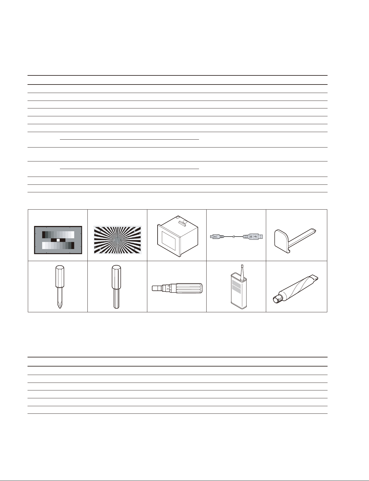
1-4. Service Tools/Measuring Equipment List
1-4-1. Service Tools
Figure No. Part No. Name Usage/Note
1 Commercially available Grayscale chart Refl ective type (16 : 9), Camera adjustment on market
2 Commercially available Star chart Refl ective type, camera adjustment on market
3 J-6394-080-A Grayscale chart Transparent type (16 : 9), Camera adjustment on market
4 J-6029-140-B Pattern box PTB-500 Camera adjustment
5 * Mini USB cable For fi rmware version-upgrade
6 3-292-755-01 XLR tool For removing the mounted circuit board
7 J-6325-110-A Bit for torque driver (M1.4/M1.7) For tightening screw
J-6325-380-A Bit for torque driver (M2)
8 J-6326-120-A Hexagon bit (For torque screwdriver) For tightening screw
(size 1.5)
9 J-6325-400-A Torque driver (3 kg.cm) (0.3 N.m) For tightening screw
J-6252-510-A Torque driver (6 kg.cm) (0.6 N.m)
!/ 7-432-114-11 Locking compound 200 g For preventing screw from being loosened
!- 7-651-000-10 Sony (SGL-601) 50 g grease Lubricant
* : This cable is supplied with PMW-EX1R.
,
1-4-2. Measuring Equipment
Use the calibrated equipment or equivalent as listed below for the adjustments.
Equipment Model name
Oscilloscope Tektronix TDS3054 or equivalent (150 MHz or more)
HD waveform monitor LEADER ELECTRONICS CORP.LV5152DA or equivalent
Frequency counter Advantest TR5821AK or equivalent
Digital voltmeter Advantest TR6845 or equivalent
Color monitor Sony HDM-20E1U/14E1U/14E5U or equivalent
Luminance meter Konica Minolta LS-110 or equivalent
1-12 (E)
PMW-EX1R

1-5. Firmware Upgrade
Upgrade the fi rmware for the PMW-EX1R through a USB connection to a computer.
For detailed information about the upgrade procedure, check the readme fi le that comes with the upgrade
software.
For inquiry or comments about the fi rmware upgrade, please contact the Sony sales offi ce.
Firmware Upgrade Procedure
Download the software for the new fi rmware upgrade onto the computer before starting these operations.
1. Check that the power switch on the PMW-EX1R is turned OFF.
2. Remove the cover on the USB maintenance connector.
Cover
USB maintenance connector
3. Use the USB connector that comes with the PMW-EX1R to connect the computer and the USB
maintenance connector.
4. Switch the power switch to CAMERA and turn the power ON.
5. Run the software for the fi rmware upgrade on the computer.
6. When the upgrade is complete, turn OFF the power and remove the USB cable.
7. Attach the cover on the USB maintenance connector.
When the PMW-EX1R is connected to the computer for the fi rst time, the driver software will need to be
installed into the computer. For more details, check the readme fi le that comes with the upgrade software.
PMW-EX1R
1-13 (E)
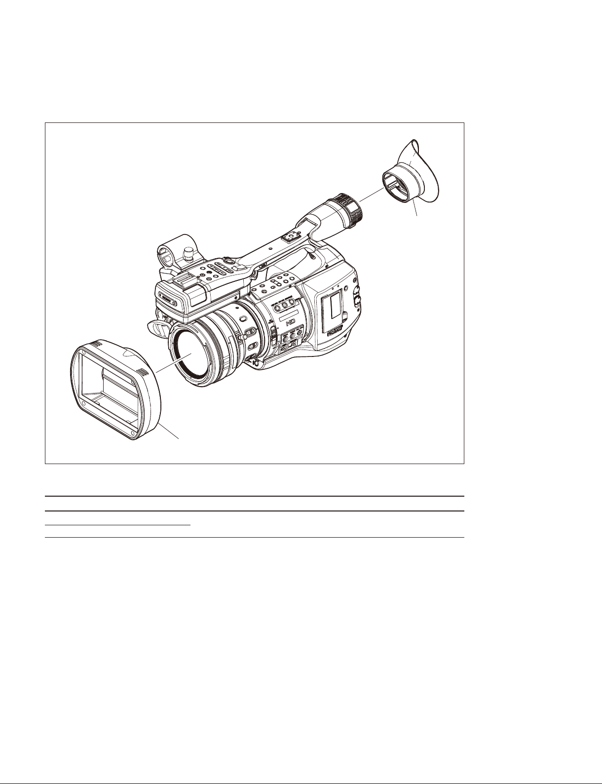
1-6. Recommended Replacement Parts
This section describes the recommended replacement parts and recommended replacement time.
1
2
ID Part name Sony part No. Recommended replacement timing
1 Eye cup 4-164-856-01 Check for deformation and deterioration from time to time.
2 Lens hood 4-179-065-01
Replace it as necessary.
1-14 (E)
PMW-EX1R

1-7. Circuit Protection Part List
1-7-1. Circuit Protection Element
This unit is equipped with the positive characteristics thermister (s) (power thermister) as the circuit
protection element. The positive characteristics thermister limits the electric current fl owing through the
circuit as the internal resistance increases when an excessive current fl ows or when the ambient tempera-
ture increases.
If the positive characteristics thermister works, turn off the main power of the unit and inspect the internal
circuit of this unit. After the cause of the fault is eliminated and the positive characteristics thermister is
cooled down, turn on the main power again. The unit works normally.
It takes about one minute to cool down the positive characteristics thermister after the main power is
turned off.
Board Ref. No. (Address) Part No. Hold Current
CN-3273 THP1 (A-1/Side A) ! 1-805-726-11 0.20 A/25dC
THP2 (A-1/Side A)
THP3 (A-1/Side A)
THP4 (A-1/Side A)
1-7-2. Replacing Fuse
w
The fuse is an essential part for safe operation.
Replace the components with Sony parts whose part numbers appear in the manual published by Sony. If
the components are replaced with any parts other than the specifi ed ones, this may cause a fi re or electric
shock.
c
If the fuse is replaced while the main power is kept on, this may cause electric shock.
Before replacing the fuse, not only turn off the POWER switch but also disconnect the cable that is connected to the DC IN connector.
This unit is equipped with fuses.
The fuses blow if an excessive current fl ows due to abnormality inside the equipment. If fuses blow, turn
off the main power of the equipment once, and inspect inside of the equipment and remove the cause of
excessive current. After that, replace the fuses.
Board Ref. No. (Address) Part No./Name
RE-272 F1 (B-1/Side B) ! 1-533-627-21 Fuse 5 A, 125 V
F2 (A-2/Side B)
PMW-EX1R
1-15 (E)

1-8. Note on Service
1-8-1. Requirements on Replacement of Boards or Parts
This section explains the necessary setups required when replacing boards or parts.
1. When any of the following boards is replaced, upgrade the fi rmware version.
All data are written at once when upgrading the fi rmware version. (Refer to Section 1-5.)
Board name : . DPR-311
. KSW-55
. SWC-50
. ASW-68
. RE-273
. TX-131
2. Adjusted values are stored in the following boards and parts. The values need to be readjusted when
they are replaced.
For readjustment, the dedicated service software “ServiceNavi-EX” is required.
(Refer to Section 4-1.)
Board name : . DPR-311
. IF-1127
Part name : . CMOS block
. EVF block
. LCD module
*1: The adjusted values for the CMOS block, the EVF block, and the LCD module are stored in the DPR-311 board.
*2: The adjusted values for the LCD module are stored in the LCD module (IF-1127 board), but the adjusted values need to be
copied to the DPR-311 board.
*1
*2
*2
3. The user setting values are stored in IC3250 on the DPR-311 board. The user data must be stored (Restore) in SxS before replacing the board and it must be read (Recall) after replacing the board.
1-8-2. Requirements on Replacement of Lens
When the lens is replaced, perform the fl ange-back adjustment.
1-8-3. Note on Replacement of Parts on the Board
1. The BI-202, BI-203 and BI-204 boards cannot be replaced on the board-level service or part-level
service. If parts become defective, replace the entire CMOS block.
2. Parts labels also cannot be replaced in the respective boards. If parts become defective, replace the
entire mounted board.
1-8-4. Description of Number Seal on the Prism
The number seal is put in the prism unit, the serial number of prism unit.
Every prism unit has its own number called prism serial number.
1-16 (E)
PMW-EX1R

1-8-5. Memory Backup Battery
For replacing the battery, refer to “Backup Battery” of the “Appendixes” in the Operating Instructions.
When the backup battery is replaced, the date and time in the internal clock need to be set. Refer to “Setting the Clock” of the “Preparations” in the Operating Instructions.
1-8-6. Unleaded Solder
Boards requiring use of unleaded solder are printed with a lead free mark (LF) indicating the solder
contains no lead.
(Caution: Some printed circuit boards may not come printed with the lead free mark due to their particular
size.)
: LEAD FREE MARK
m
. Be sure to use the unleaded solder for the printed circuit board printed with the lead free mark.
. The unleaded solder melts at a temperature about 40 dC higher than the ordinary solder, therefore, it is
recommended to use the soldering iron having a temperature regulator.
. The ordinary soldering iron can be used but the iron tip has to be applied to the solder joint for a slightly
longer time. The printed pattern (copper foil) may peel away if the heated tip is applied for too long, so
be careful.
PMW-EX1R
1-17 (E)
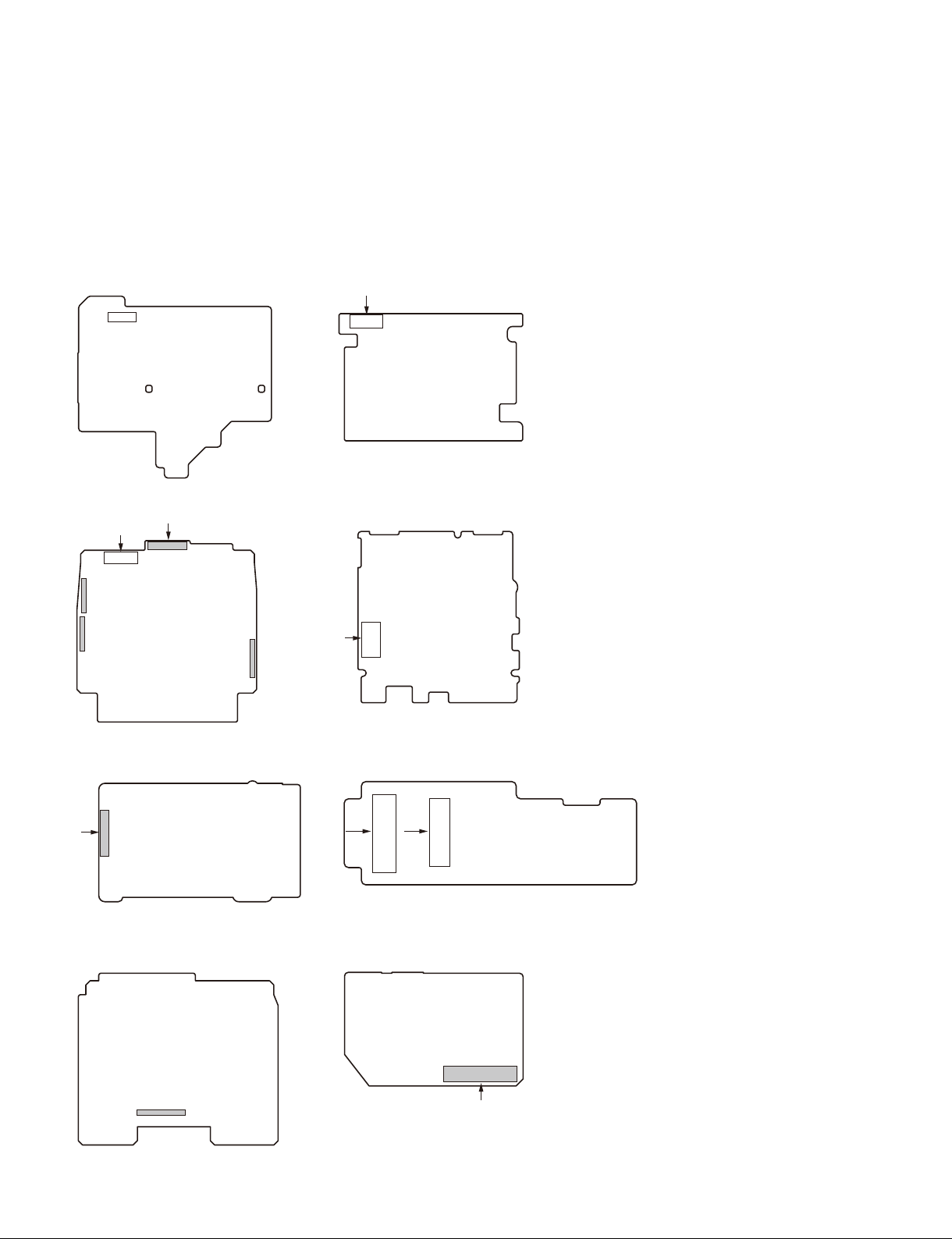
1-9. Connector Location Diagram on Board
The PWM-EX1R uses fl exible card wires and coaxial cables with connector. The following diagrams
indicate the location of each connector. The location of fl exible card cables are indicated by the circle
number A and B, and the location of coaxial cables with connector are indicated by the circle number
C and D
ASW-68 board (B side) AU-326 board (B side)
CN302
CN100
DPR-311 board (A side) KSW-55 board (A side)
CN3401
CN2401
CN2400
CN900
CN5
CN3402
EC-68 board (B side) DR-644 board (A side)
CN1
CN1
CN3
TX-131 board (B side) VIF-46 board (B side)
CN1
CN901
1-18 (E)
PMW-EX1R
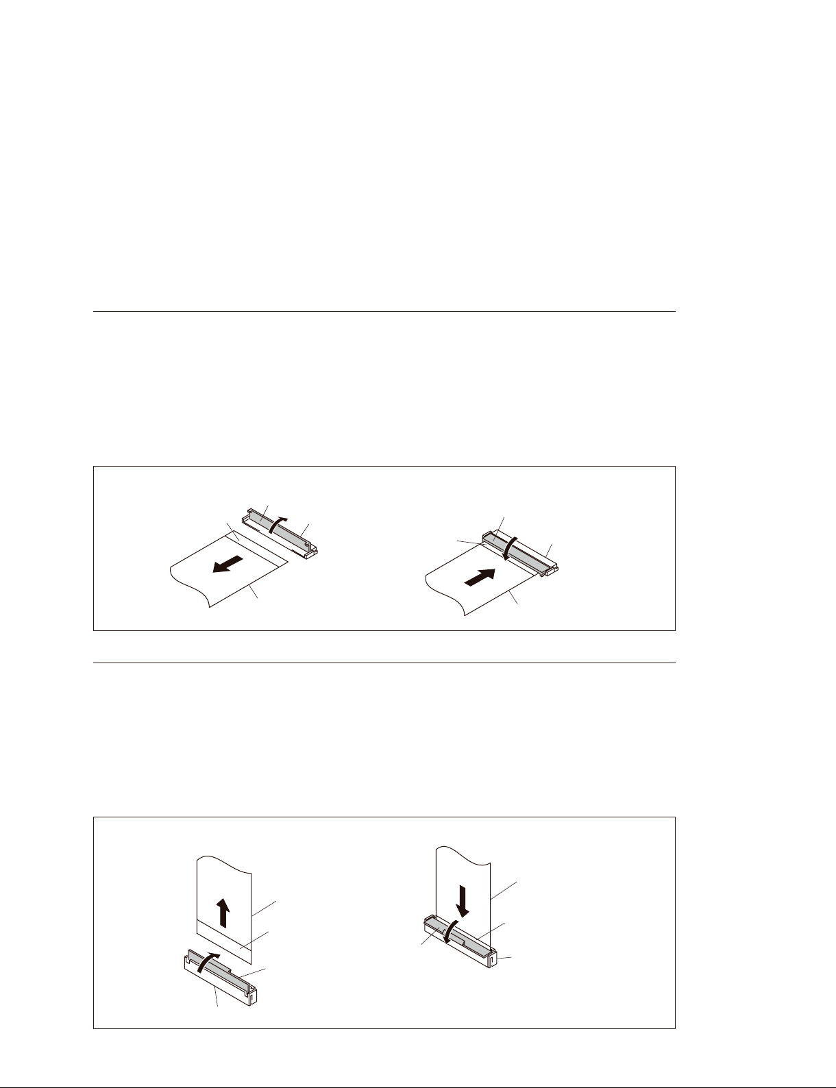
1-10. Connecting/Disconnecting the Flexible Card Wire
This unit uses the two types connectors for the fl exible card wires.
m
. Be very careful not to fold the fl exible card wire. Life of fl exible card wire will be signifi cantly short-
ened if it is folded.
. The fl exible card wire has the conductor side and the insulated area. If the conductor side and the insu-
lated area are connected in the wrong direction, the circuit will not function.
. Insert the fl exible card wire straight.
. Ensure that the conduction surface of the fl exible card wire is not contaminated.
Type A
Disconnecting
Open the latch of the connector in the direction of arrow A to unlock, and disconnect the fl exible card wire.
Connecting
1. Insert the fl exible card wire fi rmly as far as it will go, with the insulated side up.
2. Close the latch of the connector in the direction of arrow B to lock.
Disconnecting Connecting
Insulated side
Latch
A
Connector
Insulated side
Latch
B
Connector
Flexible card wire
Flexible card wire
Type B
Disconnecting
Open the latch of the connector in the direction of arrow C to unlock, and disconnect the fl exible card wire.
Connecting
1. Insert the fl exible card wire fi rmly as far as it will go, with its insulated side facing front.
2. Close the latch of the connector in the direction of arrow D to lock.
Disconnecting
Flexible card wire
Insulated side
C
Latch
Connecting
Latch
D
Flexible card wire
Insulated side
Connector
PMW-EX1R
Connector
1-19 (E)
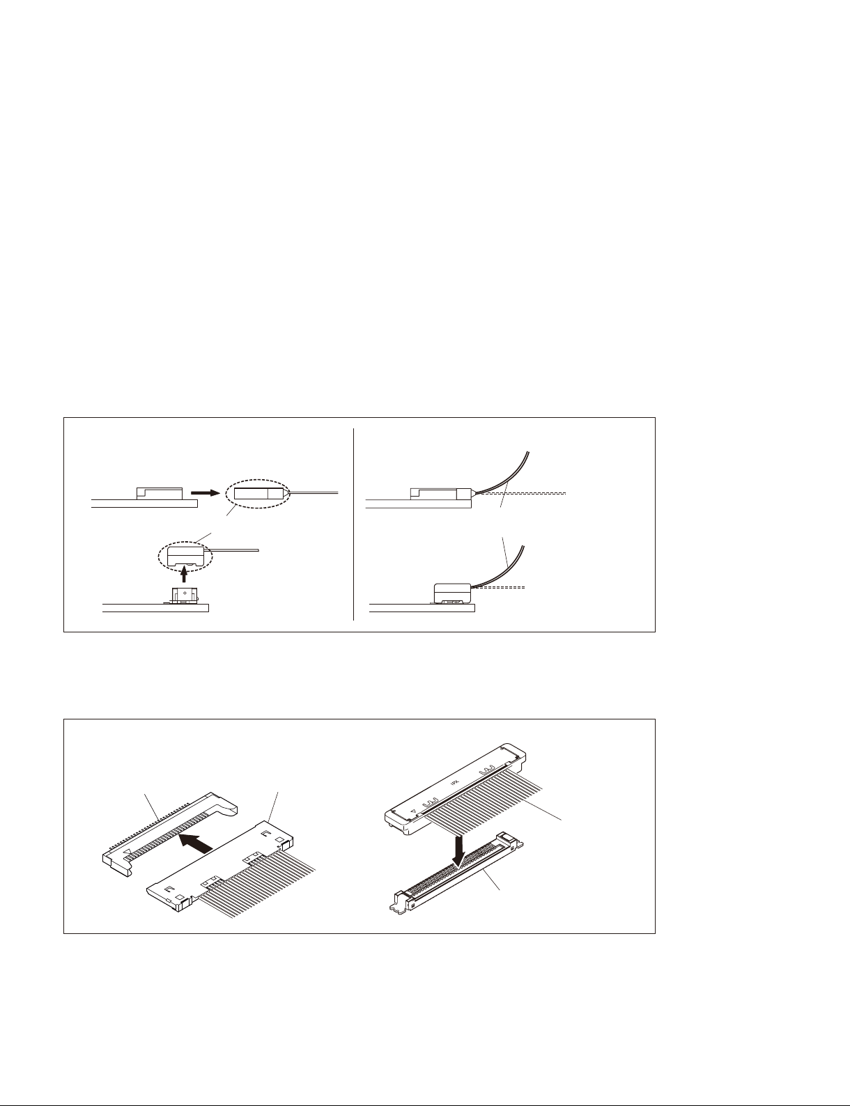
1-11. Replacing the Coaxial Cable with Connector (Fine Pitch Coaxial Cable)
This unit uses coaxial cables with connector.
The following precautions must be observed when removing or connecting the coaxial cable with connector.
m
. The coaxial cable with connector uses fi ne pitch coaxial cables. Be careful when arranging the cable.
. When disconnecting the coaxial cable with connector, do not attempt to remove by pulling the cable.
Be sure to hold the connector to remove.
. Do not insert the coaxial cable with connector at an angle.
. Check that the contact on the coaxial cable with connector is free from dirt or dust.
. When connecting the coaxial cable with connector, hold the connector, and align the polarity marks.
Then connect the coaxial cable with connector to the connector straight.
Disconnecting
Disconnect the coaxial cable with connector while holding the connector.
[OK]
Type C
Hold the connector to disconnect.
Type D
[NG]
Type C
Do not attempt to disconnect by
pulling the cables.
Type D
Connecting
Insert the connector of the coaxial cable with connector fi rmly as far as it will go.
Type C Type D
Coaxial cable
Connector
with connector
Coaxial cable
with connector
1-20 (E)
X
P
I
Connector
PMW-EX1R

Section 2
Replacement of Main Parts
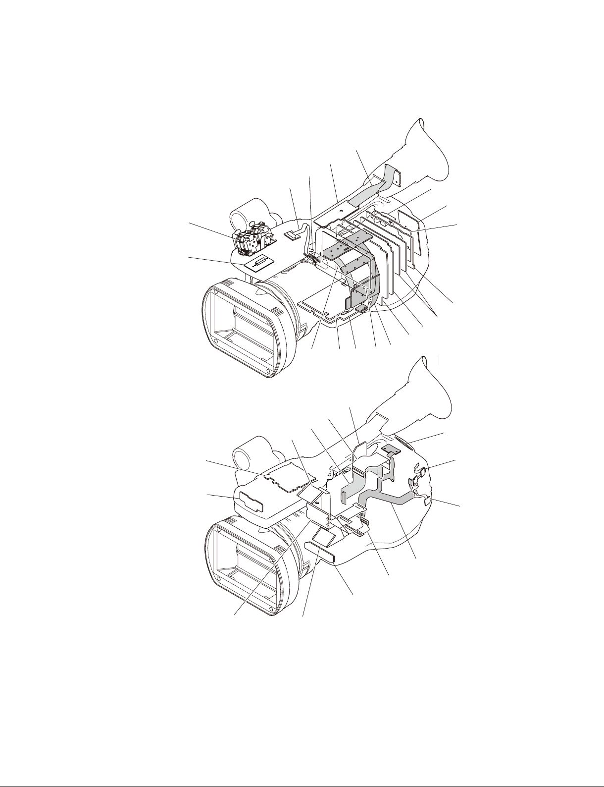
2-1. Outline of Replacement Procedures
The following fi gures show the fl ow for removing the main parts. Refer to Section 2-2 for details of the replacement proce-
dures.
START
Battery
Lithium battery
Battery lid
Outside panel
assembly
Tripod
washer (D)
Rear panel assembly
Inside panel
assembly
Case (bottom) L
Front panel
assembly
Handle
assembly
Case (bottom) R
Handle cover
(upper) assembly
Microphone
holder
EVF assembly
Cover (center) assembly
PMW-EX1R
Express card
assembly
Battery case
RE-273 board
RE-272 board
Prism assembly
TX-131 board
ND filter
DPR-311 board
Case L
assembly
Case R
2-1 (E)

2-2. Replacement Procedures
m
. When tightening screw, be sure to tighten it with the specifi ed tightening torque.
. When reinstalling the removed tapping screw again, tighten it with slightly loose torque not to damage the threads of the
component side.
. If the tightening torque is not specifi ed in a specifi c item, use the tightening torque as specifi ed below.
M2 (+) screw: 18 x 10_2 ?0.02 N.m (1.8 ?0.2 kgf.cm)
M2.6 (+) screw: 53 x 10_2 ?0.07 N.m (5.3 ?0.7 kgf.cm)
M3 (+) screw: 80 x 10 ?0.01 N.m (8.0 ?0.1 kgf.cm)
. The life of the fl exible board and the fl exible card wire will be signifi cantly shortened if they are folded. Be very careful
not to fold them.
. The coaxial cable with connector uses fi ne pitch coaxial cables. Be careful when arranging the cable.
. When disconnecting the coaxial cable with connector, do not attempt to remove by pulling the cable. Be sure to hold the
connector to remove.
2-2-1. Lithium Battery
Removing lithium battery
1. Remove the screw, and remove the lithium
battery lid.
2. Remove the lithium battery.
Lithium battery
Battery holder
3. Reinstall the lithium battery by reversing the
steps of removal.
2-2-2. Case (Bottom) L/R and Front
Panel Assembly
1. Remove the lithium battery.
(Refer to Section 2-2-1.)
2. Remove the four screws of a, and remove
the tripod washer (D).
3. Remove the fi ve screws of b, and remove
the case (bottom) L in the direction of the
arrow.
4. Remove the case (bottom) R.
M2 x 4
(Black)
Lithium battery lid
Case (bottom) L
Tripod (D)
Three claws
Claw
Case
(bottom) R
n
Be careful not to drop or damage the USB cover.
2-2 (E)
: M2 x 6 (Black)
: M2 x 4 (Black)
USB cover
PMW-EX1R
 Loading...