

Sony VAIO PCG-R505TE, VAIO R505TEK, VAIO R505TS, VAIO R505TSK, VAIO PCG-R505TEK Service Manual
...
Confidential
SERVICE MANUAL
Notebook Computer
US Model
Canadian Model
PCG-R505TE/R505TEK/R505TS/R505TSK
S400
9-872-185-11

– 2 –PCG-R505TE/R505TEK/R505TS/R505TSK (UC)
Confidential
Information in this document is subject to change without notice.
Sony and VAIO are trademarks of Sony. Microsoft, MS-DOS,
Windows, the Windows 95, Windows 98, Windows 2000 and
Windows ME logo are trademarks of Microsoft Corporation.
All other trademarks are trademarks or registered trademarks of
their respective owners. Other tr ademarks and trade names may be
used in this document to refer to the entitles claiming the marks and
names or their produces. Sony Corporation disclaims any proprietary
interest in trademarks and trade names other than its own.
Service and Inspection Precautions
1. Obey precautionary markings and instructions
Labels and stamps on the cabinet, chassis, and components identify areas
requiring special precautions. Be sure to observe these precautions, as
well as all precautions listed in the operating manual and other associated
documents.
2. Use designated parts only
The set’s components possess important safety characteristics, such as
noncombustibility and the ability to tolerate large voltages. Be sure that
replacement parts possess the same safety characteristics as the originals.
Also remember that the 0 mark, which appears in circuit diagrams and
parts lists, denotes components that have particularly important safety
functions; be extra sure to use only the designated components.
3. Always follow the original design when
mounting parts and routing wires
The original layout includes various safety features, such as inclusion of
insulating materials (tubes and tape) and the mounting of parts above the
printer board. In addition, internal wiring has been routed and clamped so
as to keep it away from hot or high-voltage parts. When mounting parts or
routing wires, therefore, be sure to duplicate the original layout.
4. Inspect after completing service
After servicing, inspect to make sure that all screws, components, and wiring
have been returned to their original condition. Also check the area around
the repair location to ensure that repair work has caused no damage, and
confirm safety.
5. When replacing chip components...
Never reuse components. Also remember that the negati ve side of tantalum
capacitors is easily damaged by heat.
6. When handling flexible print boards...
•The temperature of the soldering-iron tip should be about 270C.
•Do not apply the tip more than three times to the same pattern.
•Handle patterns with care; never apply force.
Caution: Remember that hard disk drives are easily damaged by
vibration. Always handle with care.
Caution Markings for Lithium/Ion Battery - The following or similar
texts shall be provided on battery pack of equipment or in both the
operating and the service instructions.
CAUTION: Danger of explosion if battery is incorrectly replaced.
Replace only with the same or equivalent type recommended by
the manufacturer. Discard used batteries according to the
manufacturer’s instructions.
CAUTION: The battery pack used in this de vice may present a fire
or chemical burn hazard if mistreated. Do not disassemble, heat
above 100°C (212°F) or incinerate.
Dispose of used battery promptly.
Keep away from children.
CAUTION: Changing the back up battery.
• Overcharging, short circuiting, reverse charging, multilation
or incineration of the cells must bi avoided to prevent one or
more of the following occurrences; release of toxic materials,
release of hydrogen and/or oxygen gas, rise in surface
temperature.
• If a cell has leaked or vented, it should be replaced
immediately while avoiding to touch it without any protection.

– 3 –
PCG-R505TE/R505TEK/R505TS/R505TSK (UC)
Confidential
TABLE OF CONTENTS
Section Title Page
CHAPTER 1. REMOVAL
1-1. Flowchart ......................................................................... 1-1
1-2. Main Electrical Parts Location Diagram .........................1-2
1-3. Removal ...........................................................................1-2
1. Key Board Unit ................................................................ 1-2
2. Palm Rest Section ............................................................ 1-3
3. SWX-72 Board, Encoder (Rotaly), Touch Pad ................ 1-3
4. IFX-141 Board ................................................................. 1-4
5. Battery.............................................................................. 1-4
6. HDD................................................................................. 1-5
7. Cover (Bottom LF/LR/R) ................................................ 1-5
8. Frame Housing................................................................. 1-6
9. SWX-76 Board, Speaker (L/R)........................................ 1-6
10. CNX-119 Board............................................................... 1-7
11. Modem Card .................................................................... 1-7
12. CNX-121 Board............................................................... 1-8
13. DC Fan............................................................................. 1-8
14. MBX-48 Board ................................................................ 1-9
15. Heatsink (CPU)................................................................ 1-9
16. CNX-120 Board, LCD Section, CNX-131 Board ......... 1-10
17. Bezel .............................................................................. 1-11
18. LCD Unit ....................................................................... 1-11
19. LEX-29 Board, Inverter Unit ......................................... 1-12
(to 1-12)
CHAPTER 2. SELF DIAGNOSTICS.......................... 2-1
Please confirm “Self Diagnostics” method which will be informed
you with distribution of “Self Diagnostics” software.
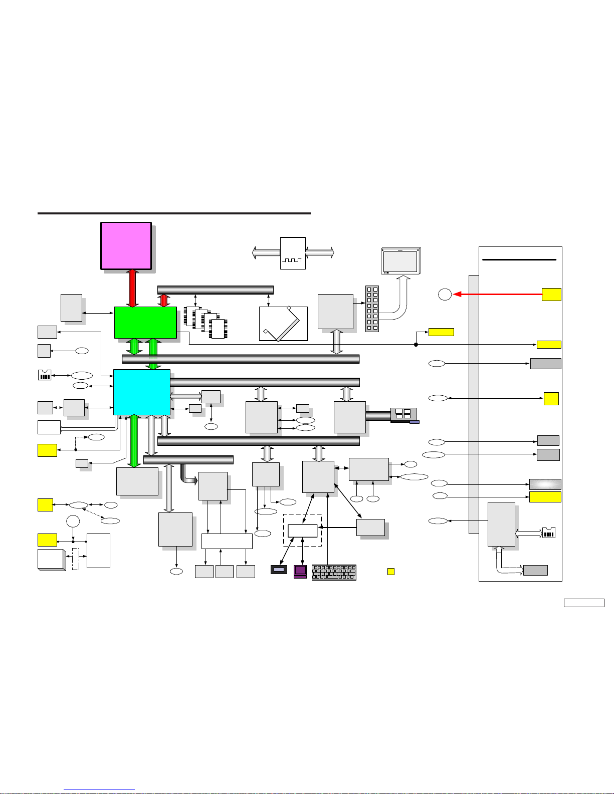
CHAPTER 3. BLOCK DIAGRAM............................... 3-1
(to 3-2)
CHAPTER 4. FRAME HARNESS DIAGRAM........ 4-1
(to 4-2)
CHAPTER 5. EXPLODED VIEWS AND
PARTS LIST
5-1. Main Section.................................................................... 5-1
5-2. LCD Section .................................................................... 5-3
5-3. Accessories ...................................................................... 5-5
(to 5-5)
• Abbreviations
UC : US model / Canadian model
1-1 PCG-R505TE/R505TEK/R505TS/R505TSK (UC)
Confidential
CHAPTER 1.
REMOVAL
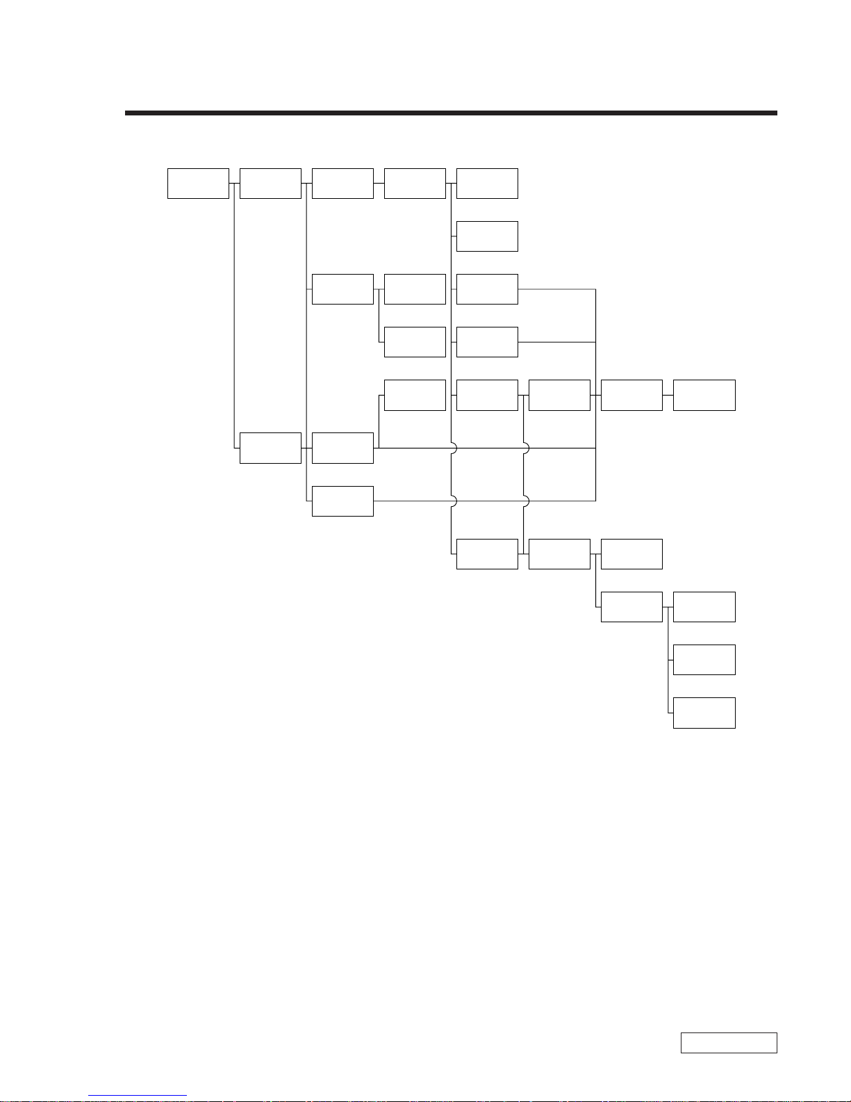
1-1. Flowchart
• P XX means pages that appears in this manual.
• Remember that hard disk drives are easily damaged by vibration. Always handle with care.
POWER
OFF
KEY BOARD
UNIT
P 1-2
PALM REST
SECTION
P 1-3
COVER
(BOTTOM LF/
LR/R)
P 1-5
FRAME
HOUSING
P 1-6
SWX-72
BOARD
ENCODER
(ROTALY)
IFX-141
BOARD
P 1-3
SWX-76
BOARD
P 1-6
P 1-3
TOUCH
PAD
P 1-3
P 1-6
CNX-119
BOARD
SPEAKER
(L/R)
P 1-7
CNX-121
BOARD
P 1-8
MBX-48
BOARD
P 1-9
HEATSINK
(CPU)
P 1-9
DC
FAN
P 1-8
CNX-120
BOARD
P 1-10
CNX-131
BOARD
P 1-10
LEX-29
BOARD
P 1-12
LCD
SECTION
P 1-10
LCD
UNIT
P 1-11
INVERTER
UNIT
P 1-12
MODEM
CARD
P 1-7
P 1-4
HDD
P 1-5
BEZEL
P 1-11
BATTERY
P 1-4
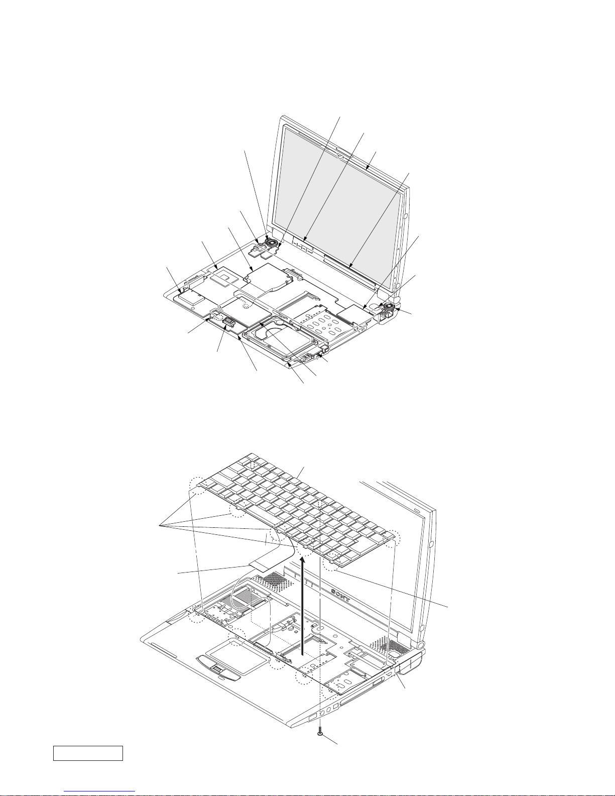
1-2PCG-R505TE/R505TEK/R505TS/R505TSK (UC)
Confidential
2 Claw
2 Claw
2 Claw
3
4 Harness
Key Board Unit
1 M2X6
1-2. Main Electrical Parts Location Diagram
1-3. Removal
1. Key Board Unit
CNX-131 Board
LEX-29 Board
Inverter Unit
Modem Card
SWX-76 Board
Speaker (R)
Speaker (L)
CNX-119 Board
SWX-72 Board
IFX-141 Board
MBX-45 Board
CNX-121 Board
DC Fan
Encoder (Rotaly)
Battery
Touch Pad
HDD
LCD Unit
1-3 PCG-R505TE/R505TEK/R505TS/R505TSK (UC)
Confidential
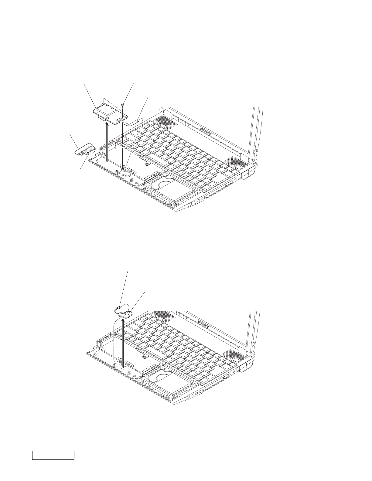
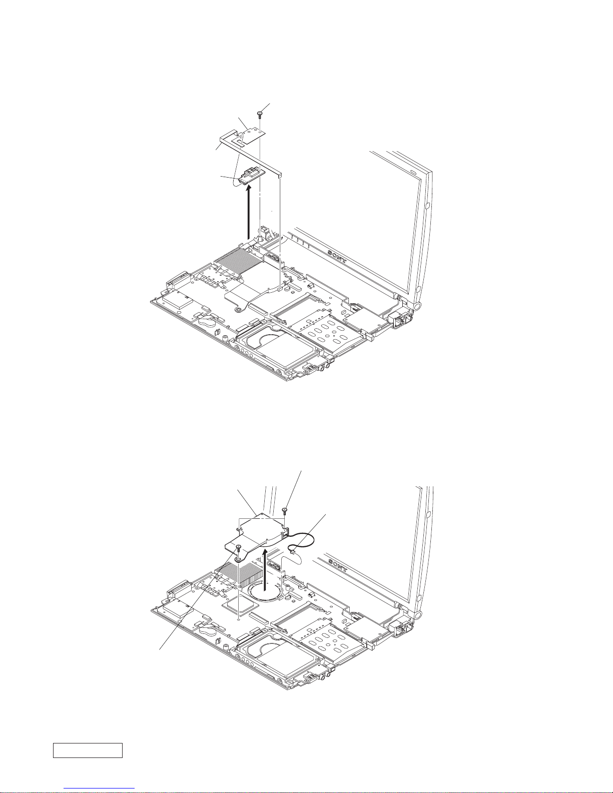
2. Palm Rest Section
3. SWX-72 Board, Encoder (Rotaly), Touch Pad
3 FFC (10P)
Palm Rest Section
1 M2X6
1 M2X6
2
1 FFC (10P)
3 M2X4
6
9
4
5 M1.4X3.5
7 Claw
7 Claw
7 Claw
7 Claw
Touch Pad
2 Flexible Flat
Cable (12 core)
8 Escutcheon (TP)
SWX-72 Board
Encoder (Rotaly)
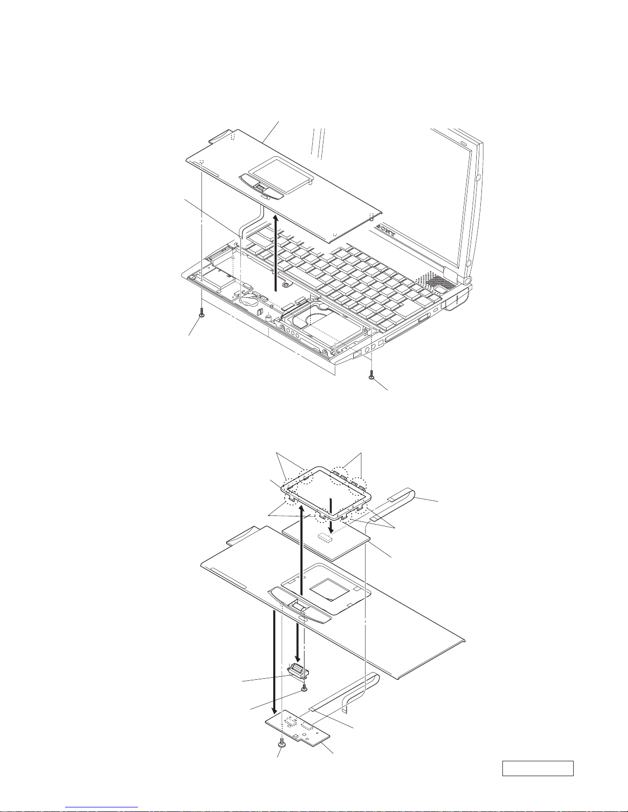
1-4PCG-R505TE/R505TEK/R505TS/R505TSK (UC)
Confidential
4 M2X4
1 FFC (12P)
2 Claw
3 Cover (Bottom LF)
IFX-141 Board
5
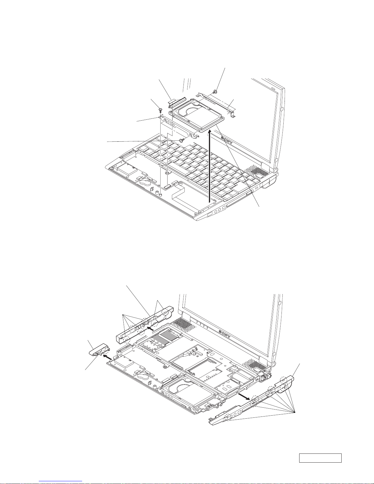
4. IFX-141 Board
5. Battery
1 Harness
Nickel Hydrogen Battery
2
1-5 PCG-R505TE/R505TEK/R505TS/R505TSK (UC)
Confidential
1 Claw
3 Claw
3 Claw
5 Claw
Cover
(Bottom LF)
Cover (Bottom LR)
Cover (Bottom R) Assy
2
4
6
6 M3X4
2 M2X4
4 M3X4
1 FPC (HDD)
7 Bracket (HDD F)
5 Bracket (HDD R)
HDD 20 GB
(PCG-R505TSK/R505TS)
HDD 15 GB
(PCG-R505TEK/R505TE/R505DE)
3
6. HDD
7. Cover (Bottom LF/LR/R)
1-6PCG-R505TE/R505TEK/R505TS/R505TSK (UC)
Confidential
8. Frame Housing
9. SWX-76 Board, Speaker (L/R)
3 Undo four claws and
remove the cover (BP).
3 Undo four claws and
remove the cover (BP).
4 M2X6
Frame Housing
5
1 Harness
2 FFC (8P)
8 Speaker
Bracket
6 Speaker Bracket
4 Harness
2 Tapping
2X4
5 Button (Power)
1 FFC (8P)
SWX-76 Board
9
3
7
Speaker (L)
Speaker (R)
1-7 PCG-R505TE/R505TEK/R505TS/R505TSK (UC)
Confidential
1 M2X2.5
1 M2X2.5
4 Harness (2P)
3
Modem Card
2 Connector
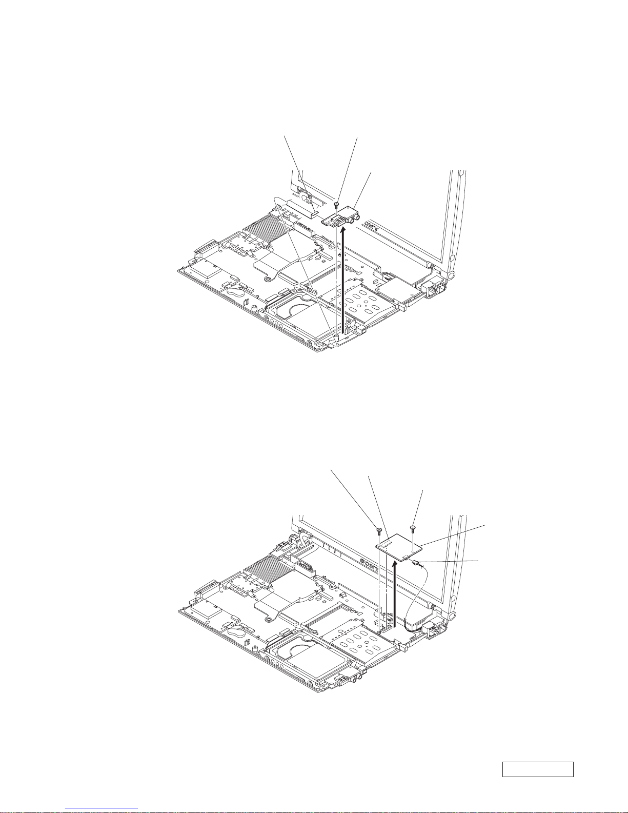
10. CNX-119 Board
11. Modem Card
3 FFC (20P)
1 M2X4
2
CNX-119 Board
1-8PCG-R505TE/R505TEK/R505TS/R505TSK (UC)
Confidential
1 M2X4
3
4 FFC (10P)
CNX-121 Board
2 Shield CNX1
DC Fan (With Heatsink)
2 M2X6
2 M2X6
1 Harness
3
12. CNX-121 Board
13. DC Fan
1-9 PCG-R505TE/R505TEK/R505TS/R505TSK (UC)
Confidential
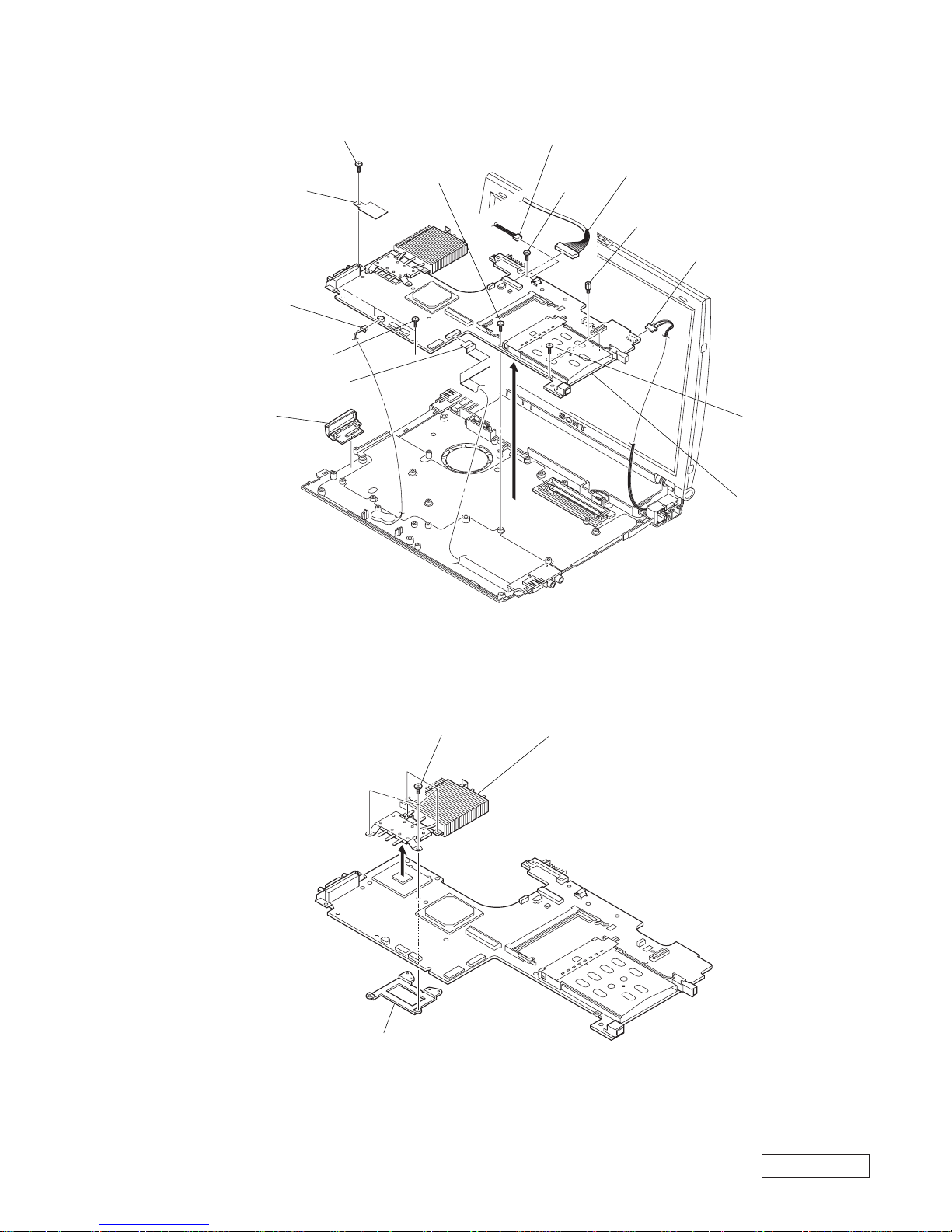
14. MBX-48 Board
15. Heatsink (CPU)
qa Lid (VGA) Assy
4 FFC (20P)
7 M2X2.5
5 M2X4
5 M2X4
5 M2X4
5 M2X4
9
2 Harness (Power 3P)
1 Harness (LCD)
8 Spacer (MBX)
0 RJ-45 (For Internal)
Harness
MBX-48 Board
3 Harness
6 Shield MBX1
1 P2X3
2
3 Bracket (CPU)
Heatsink (CPU)
*
The heatsink (CPU) must be installed
with the thermal sheet (CPU) in soft state to
protect the CPU from the stress.
For this purpose, with the thermal sheet
(CPU) pasted, warm the heatsink (CPU) to
about 70 °C, and when the thermal sheet
(CPU) has become soft, install the heatsink
(CPU) on the main board.

1-10PCG-R505TE/R505TEK/R505TS/R505TSK (UC)
Confidential
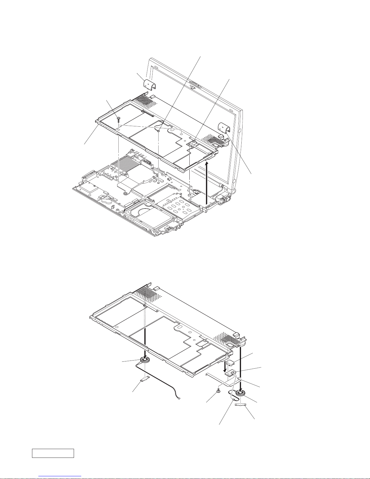
16. CNX-120 Board, LCD Section, CNX-131 Board
8 M2X4
5 M2X5
1 M2X5
6 M2X5
7 M2X4
0 Harness (Power 3P)
qd Cover (BBL)
CNX-131 Board
3 Harness (2P)
LCD Section
CNX-120 Board
4 Harness
(LCD)
9
2
qa
qs Cover (BBR)
1-11 PCG-R505TE/R505TEK/R505TS/R505TSK (UC)
Confidential
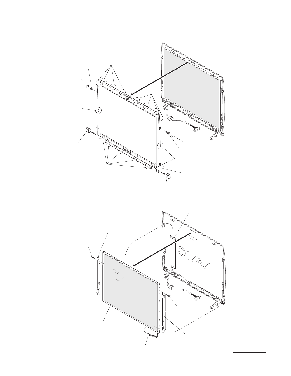
17. Bezel
18. LCD Unit
1 Cover (DR)
2 Cover (DL)
5 Claw
5 Claw
5 Claw
5 Claw
5 Claw
6
4 M2X5
4 M2X5
3 Hole Blind (Side)
3 Hole Blind (Side)
Housing (Bezel) Assy
6 M2X3
4 M2X3
7 Bracket (LCD-L)
5 Bracket (LCD-R)
1 Harness
LCD Unit
3 Harness (LCD)
2
1-12PCG-R505TE/R505TEK/R505TS/R505TSK (UC)
Confidential
(END)
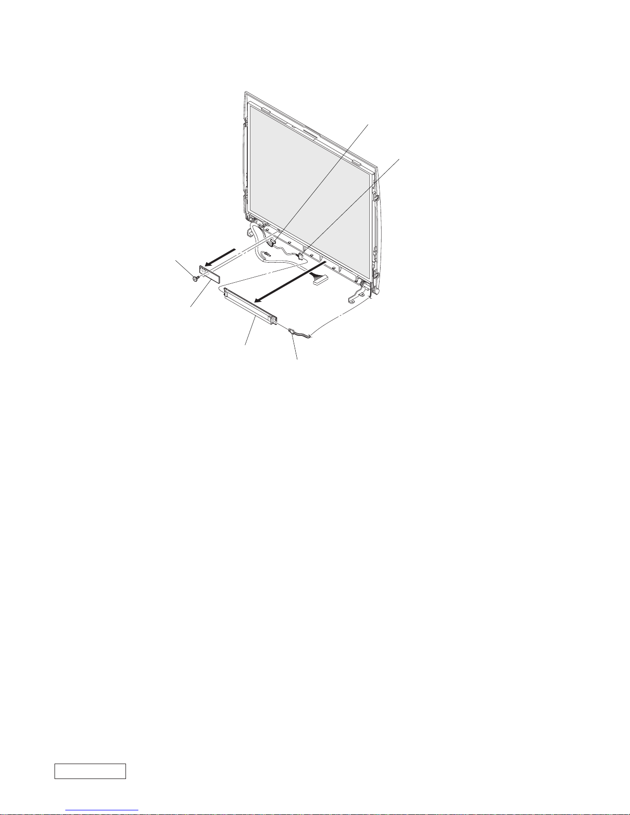
19. LEX-29 Board, Inverter Unit
3 Harness
5 Harness
6 Harness
1 M2X3
2
4
Inverter Unit
LEX-29 Board

2-1 PCG-R505TE/R505TEK/R505TS/R505TSK (UC)
Confidential
CHAPTER 2.
SELF DIAGNOSTICS
< ATTENTION >
Please confirm “Self Diagnostics” method which will be informed
you with distribution of “Self Diagnostics” software.
(END)
PCG-R505TE/R505TEK/R505TS/R505TSK (UC)
Confidential
3-1 3-2
CHAPTER 3.
BLOCK DIAGRAM
(END)
Graphics & Memory
CONTROLLER
HUB
GMCH2-m
Graphics & Memory
CONTROLLER
HUB
GMCH2-m
Bus #0 Dev #0, 1,2
IO Control Hub
ICH2-m
IO Control Hub
ICH2-m
Bus #0 Dev #8,31
i.LINK
PHY &
ATAPI
Bridge
i.LINK
PHY &
ATAPI
Bridge
Internal
HDD
VGA DB-15
Docking Station
USB(B) CONN x1
PHONE
OUT
RJ11
BATTERY
DC-IN
CONN
BAT CONN
POWER
SUPPLY
&
CHARGE
R
1/1
MIC
IN
RJ45
USB
CONN
MS
CONN
Port Connector 100+4pin
Coppermine
Processor Core with 256/
128KB L2 Cache
BGA2
Coppermine
Processor Core with 256/
128KB L2 Cache
µ BGA2
PCI BUS(3.3V)
DVO(3.3V)
100MHz Memory Bus
SO-DIMM
PCI-1394
TI
TSB43LV22
PCI-1394
TI
TSB43LV22
Bus #1 Dev #8
CARDBUS
RICOH
RC5C475II
CARDBUS
RICOH
RC5C475II
Bus #1 Dev # 12
CardBus/16bitCard
i.LINK
PC Card
Connector
1 Slot
H8S/2149
KBC/EC
SPIC
H8S/2149
KBC/EC
SPIC
VCH
VCH
LCD CONN
SONY
12 XGA
LCD &
INVERTER
Cable
ROW#0,1
ROW#2,3
CLKGEN
IMI
C9835
Ether
PHY
Ether
PHY
KeyBoard
Membrane
RJ11
JOG
Contro ller
JOG
Controller
Cable( Primary IDE)
On Board
Memory
VGA DB-15
Printerx1
Serialx1
FDD x1
USB1
CD-ROM/
RW/DVD
USB(A) CONN x1
LPC
Audio
AD1881A
Audio
AD1881A
Memory
Stick
Module
Memory
Stick
Module
RJ45
LAN-A1
DC-IN
CONN
i.LINK0
i.LINK0
LAN-A0
LAN
LAN-A1
LAN
AC LINK
RJ11
AMP
Headphone
MIC
Speaker
Speaker
L&R
FWH
(Flash BIOS ROM)
FWH
(Flash BIOS ROM)
DCin
DCin
i.LINK1
i.LINK1
Super I/O
SMsC
LPC47N227
Super I/O
SMsC
LPC47N227
I/O Expander
& SM BUS MUX
I/O Expander
& SM BUS MUX
FAN
BATTERY
LID ATF
USB1
USB 0
USB 2
Seri al
Paral lele
Serial
Parallele
Refer to Clock Generator
Block Diagram
SMBUS
USB
CONN
FDD
FDD
i.LINK
SWX-72
Board
TouchPad
JOG
USB1
USB3
USB3
Display
Cash
Display
Cash
EEPROM
EEPROM
For Password
EEPROM
EEPROM
For LAN
SMB2
EEPROM
EEPROM
For i.LINK
MDC
(Modem Daughter
Card)
Module
MDC
(Modem Da
ughter
Card)
Module
is can not connect on main unit
when connected docking stataion
CPU Local Bus

PCG-R505TE/R505TEK/R505TS/R505TSK (UC)
Confidential
4-1 4-2
(END)
CHAPTER 4.
FRAME HARNESS DIAGRAM
81
18
1
2
FROM board connector (direct connection)
Harness (connector at both end)
Harness (soldered at one end)
1
A
Y
CN4004
USB
CN4002
MIC/LINE
INPUT
CN4003
HEAD POHNE
KEY BOARD
24 1
CN1902
LITHIUM ION
BATTERY PACK
81
CN2702
Rear
NICKEL HYDROGEN
BATTERY
CN2802
2
1
HDD
PCG-R505TSK/R505TS: 20GB
PCG-R505TEK/R505TE: 15GB
49150
2
CN2201
CNX-119 BOARD
SIDE B
1
20
CN4001
CN1301
i.LINK
PC
CARD
CONNECTOR
PC
CARD
MODEM
CARD
30
29
1
2
J1
30
29
1
2
34
1
68
35
CN1602
CON2
CN5002
CN5001
MODULAR
JACK
SPEAKER
L ch
CN1711
1
2
1
2
DC FAN
(WITH HEATSINK)
M
CN102
CNX-121 BOARD
SIDE B
CN4302
USB
CN702
EXT. DISPLAY
1
3
CN2801
CN4401
DC IN
CNX-131 BOARD
SIDE A
1
3
CN4402
1
20
CN1710
10
1
CN4301
1
12
CN3051
1
10
CN2003
1
12
CN4501
1
10
CN4701
1
12
CN4702
S4703
S4701
S4702
S4704
ENCODER
(ROTALY)
SWX-72 BOARD
SIDE A
EXTENSION
MEMORY MODULE
PCGA-MM64N/MM128N
12
59 60
61 62
143 144
CN502
131
CN701
299
1 100
CN1401
LCD
LEX-29 BOARD
SIDE A
CN4901
INVERTER UNIT
281
7
CN2004
8
1
CN4801
CN4802
2
1
SPEAKER
R ch
POWER
SWX-76 BOARD
SIDE B
IFX-141 BOARD
SIDE A
MBX-48 BOARD
SIDE A
Side L
DOCKING STATION
PCGA-DSD5/DSM5
CN1502
HARNESS (LCD)
HARNESS (POWER 3P)
10
1
CN3071
FCC (10P)
FCC (12P)
10
1
CN4502
MEMORY
STICK
TOUCH PAD
CENTER
BUTTON
LEFT
BUTTON
RIGHT BUTTON
FCC (10P)
FLEXIBLE FLAT CABLE (12 CORE)
FPC (HDD)
CN1202
FCC (8P)
S4801
RJ-45 HARNESS (FOR INTERNAL)
HARNESS (2 PIN)
CNX-120 BOARD
SIDE B
NETWORK
Side R
FLEXIBLE FLAT CABLE (NI SHIELD) 20P
PCG-R505TE/R505TEK/R505TS/R505TSK (UC)
Confidential
26 4-652-913-01 COVER (BP)
27 1-476-671-21 KEY BOARD UNIT (US)
28 1-763-688-11 FAN, DC (WITH HEATSINK)
29 1-815-304-11 CONNECTOR, PC CARD 1 SLOT
30 4-654-327-01 SHEET (GMCH), THERMAL
31 4-653-411-01 SHEET(PC CARD), INSULATING
* 32 4-652-932-01 HEATSINK (CPU)
* 33 4-652-924-01 BRACKET (VGA)
34 A-8049-520-A (R505TSK/R505TS)...
MBX-48 (850SS-H) (S)
34 A-8049-521-A (R505TEK/R505TE)...
MBX-48 (750SS-H) (S)
* 35 4-652-925-01 BRACKET (CPU)
36 1-960-827-31 HARNESS (2 PIN)
37 1-761-380-22 CARD, MODEM
38 4-653-412-01 SHEET (BOTTOM), INSULATING
39 1-961-140-11 HARNESS, RJ-45 (FOR INTERNAL)
40 X-4623-577-1 LID (DOC) ASSY
41 4-651-941-02 COVER (BBL)
42 A-8066-651-A COMPLETE PWB CNX-120
43 4-652-942-02 COVER (BBR)
44 1-790-750-13 FPC (HDD)
* 45 4-652-927-01 BRACKET (HDD R)
46 1-772-996-11 (R505TSK/R505TS)...
HDD (20.0GB-DK23BA-20)
46 1-796-070-11 (R505TEK/R505TE)...
HDD (15.0GB)-DK23BA
* 47 4-652-926-01 BRACKET (HDD F)
48 X-4623-575-2 HOUSING (BOTTOM) ASSY
49 A-8066-648-A COMPLETE PWB CNX-119
50 1-757-786-11 FLEXIBLE FLAT CABLE (NI SHIELD) 20P
51 4-641-449-01 FOOT (F)
52 X-4623-576-2 COVER (BOTTOM R) ASSY
53 4-652-918-01 LID (ETHER)
54 X-4623-578-1 LID (VGA) ASSY
55 4-654-610-02 COVER AIR DUCT
56 1-756-038-11 BATTERY, NICKEL HYDROGEN
57 1-961-147-11 HARNESS (POWER 3P)
58 A-8066-647-A COMPLETE PWB IFX-141
59 1-757-784-11 FFC (12P)
60 4-641-779-01 SPRING (BT), COMPRESSION COIL
61 1-757-792-11 FFC (10P)
62 A-8066-649-A COMPLETE PWB CNX-121
63 A-8066-650-A COMPLETE PWB CNX-131
64 4-653-432-01 CLAMP
65 4-654-326-01 SHEET (CPU), THERMAL
66 4-654-384-01 GND GASKET 5X15X1
67 4-654-450-02 SHEET (COVER LR)
68 4-654-382-01 CUSHION HDD CONNECTOR
69 4-654-518-01 SHIELD CNX 1
70 4-653-506-02 SHEET (MODEM)
71 4-654-517-01 SHIELD MBX 1
72 4-654-239-01 INSULATING SHEET
73 4-652-943-01 FOOT (R)
74 8-759-695-59 (R505TEK/R505TE)...
IC MT4LSDT864HG-10EB1
75 1-695-514-21 JACK (SMALL TYPE) 1P (HEAD PHONE)
76 1-793-100-11 CONNECTOR, USB
77 1-779-745-31 JACK, DC
B1 4-644-492-31 ACE (M2), LOCK (2X4)
B2 3-930-461-01 SCREW (DIA. 1.4X3.5), PRECISION
B3 4-644-492-01 ACE (M2), LOCK (2X6)
B5 4-648-320-01 TAPPING (M2) (2X4)
* B6 4-635-966-01 SCREW (HEX)
B7 4-645-016-31 ACE (M2) (DIA. 4.6), LOCK (2X2.5)
B8 7-621-255-15 SCREW +P 2X3
B9 4-651-989-11 SPACER (MBX)
B10 4-635-301-01 SCREW M3X4
B11 4-654-273-01 ACE (M2), LOCK (2X5)
B12 4-644-492-51 ACE (M2), LOCK
5-1 5-2
CHAPTER 5.
EXPLODED VIEWS AND PARTS LIST
NOTE:
• The mechanical parts with no reference number in the
exploded views are not supplied.
• Items marked “ * ” are not stocked since they are seldom
required for routine service. Some delay should be
anticipated when ordering these items.
• When the same reference numbers are written down in the
list, please use the one listed in the first place as the main
part.
5-1. Main Section
Ref.No. Part No. Description
The components identified by mark 0 or
dotted line with mark 0 are critical for safety.
Replace only with part number specified.
Les composants identifiés par une marque
0 sont critiques pour la sécurité.
Ne les remplacer que par une pièce portant
le numéro spécifié.
*
To paste the thermal sheet (CPU) (65) to the heatsink
(CPU), warm the thermal sheet (CPU) adequately until it
becomes soft.
For further information, refer to the removal (page 1-9).
H
A
B
C
A
D
E
E
G
L
I
N
O
Q
K
J
I
G
J
B
K
L
H
M
D
P
Q
M
O
F
C
N
F
1
B1
B1
B1
B1
B3
B11
B11
B5
B1
B1
B2
2
3
4
5
7
8
9
10
11
12
67
13
14
68
15
16
17
24
26
23
22
21
20
19
17
52
53
50
51
B1
B3
B3
B3
B1
B10
B10
B1
B1
B1
B12
B7
B6
B1
B1
B1
B12
B12
B1
B9
B7
B7
49
76
75
48
47
46
45
44
43
73
39
40
41
60
59
54
55
56
58
57
61
62
76
77
63
33
71
34
65
32
64
30
66
31
28
29
B1
36
37
B8
B3
B3
35
74
38
72
18
20
25
26
27
6
P
B11
42
70
69
R
B12
R
Ref.No. Part No. Description
1 A-8066-644-A COMPLETE PWB SWX-72
2 1-757-785-11 FFC (10P)
3 1-476-060-31 ENCODER (ROTALY)
4 4-652-922-02 BRACKET (JOG)
5 4-652-940-02 DETECTOR, LATCH
6 4-652-921-02 BUTTON (TP-R)
7 4-652-920-02 BUTTON (TP-L)
8 4-652-935-02 LENS (PALM REST)
9 4-652-907-01 HOUSING (PALM REST)
10 4-652-944-01 COVER, LENS
11 4-652-909-02 COVER (BOTTOM LF)
12 4-652-910-O2 COVER (BOTTOM LR)
13 4-652-923-02 ESCUTCHEON (TP)
14 4-653-410-01 SHEET (TP), INSULATING
15 1-772-529-61 PAD, TOUCH
16 1-790-729-11 CABLE, FLEXIBLE FLAT (12 CORE)
17 4-653-370-01 BRACKET, SPEAKER
18 1-757-787-11 FFC (8P)
19 1-544-847-11 SPEAKER (16MM, WITH HARNESS) R
20 4-653-371-01 CUSHION, SPEAKER
21 A-8066-645-A COMPLETE PWB SWX-76
22 4-653-372-01 CUSHION BUTTON PW
23 4-652-919-01 BUTTON (POWER)
24 1-544-846-11 SPEAKER (16MM, WITH HARNESS) L
25 X-4623-665-2 HOUSING (FRAME) ASSY
PCG-R505TE/R505TEK/R505TS/R505TSK (UC)
Confidential
5-3 5-4
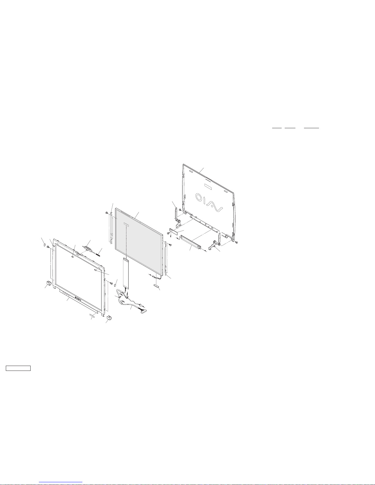
5-2. LCD Section
Ref.No. Part No. Description
C
C
B
A
B
A
111
B4
B4
B13
B13
B4
B13
112
113
114
110
109
107
106
105
102
101
117
119
116
104
103
B13
B4
104
103
108
115
118
101 X-4623-574-2 HOUSING (BEZEL) ASSY
102 4-652-902-01 COVER (DL)
103 4-652-933-01 BLIND (SIDE), HOLE
104 4-652-934-01 BLIND (LCD), HOLE
105 4-652-938-01 CUSHION (LATCH)
106 4-652-904-02 LATCH
107 4-639-623-11 SPRING (LATCH), COIL
* 108 4-652-898-01 BRACKET (LCD-L)
109 A-8048-165-A LCD UNIT (12.1 TFTXGA) (S)
110 4-652-900-01 TILT UNIT (L)
111 X-4623-573-1 HOUSING (DISPLAY) ASSY
112 4-652-901-01 TILT UNIT (R)
113 1-476-317-12 INVERTER UNIT
114 A-8066-646-A COMPLETE PWB LEX-29
* 115 4-652-899-01 BRACKET (LCD-R)
116 1-961-063-11 HARNESS (LCD)
117 4-652-903-01 COVER (DR)
118 4-654-412-01 SPACER (LCD)
119 4-654-007-01 (R505TSK)...LABEL (ID (U))
119 4-654-007-11 (R505TS)...LABEL (ID (U))
119 4-654-007-21 (R505TEK)...LABEL (ID (U))
119 4-654-007-31 (R505TE)...LABEL (ID (U))
B4 4-643-356-01 SCREW (M2X5)
B13 4-644-492-21 ACE (M2), LOOCK (2X3)
5-5 PCG-R505TE/R505TEK/R505TS/R505TSK (UC)
Confidential
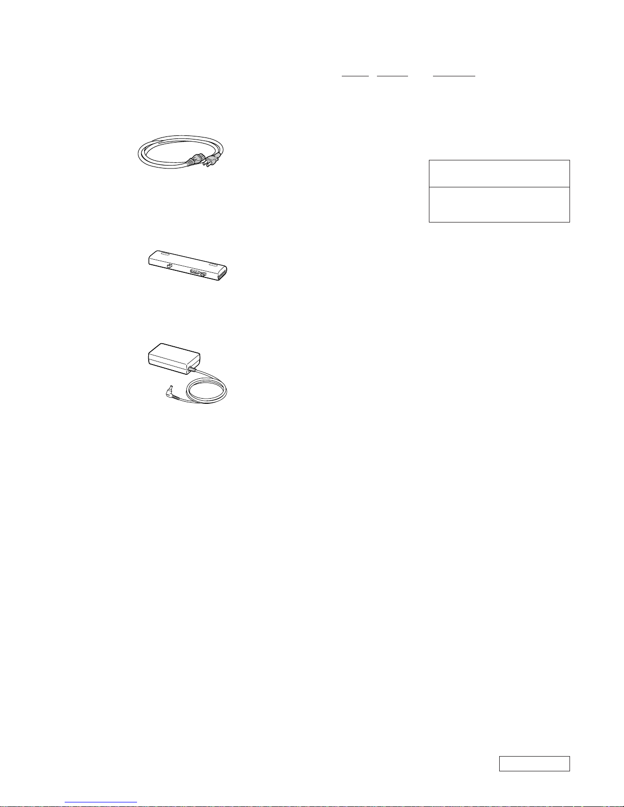
201
Power Cord (1)
203
Battery Pack (1)
204
AC Adaptor (1)
(END)
5-3. Accessories
Ref.No. Part No. Description
The components identified by mark 0 or
dotted line with mark 0 are critical for safety .
Replace only with part number specified.
Les composants identifiés par une marque
0 sont critiques pour la sécurité.
Ne les remplacer que par une pièce portant
le numéro spécifié.
ACCESSORIES
***********
0 201 1-757-562-21 CORD, POWER
203 1-756-152-21 BATTERY PACK, LITHIUM ION (L)
0 204 1-476-342-12 ADAPTOR, AC
4-653-824-11 QUICK (START)

®
VAIO
R505
SuperSlim Pro™
Notebook Quick Start
PCG-R505TSK, PCG-R505TS
PCG-R505TEK, PCG-R505TE

Contents
Notice to Users ......................................................3
Owner’s Record..........................................................................................4
Safety Information......................................................................................4
Regulatory Information .............................................................................. 6
Disposal of Lithium-Ion Battery..................................................................8
Industry Canada Notice ..............................................................................8
Welcome ...............................................................11
Features ................................................................................................... 11
Unpacking Your Notebook........................................................................ 12
Notes on Use............................................................................................ 14
Setting Up Your VAIO® Notebook .....................17
Locating Controls and Connectors ..........................................................17
Connecting a Power Source ..................................................................... 20
Starting Your Notebook............................................................................ 26
Shutting Down Your Notebook.................................................................27
Adding Memory ...................................................29
Related Safety Guidelines ........................................................................ 29
To Install a Memory Module.....................................................................30
To Remove a Memory Module ................................................................. 33
About the Software on Your Notebook .............35
Overview of the Software on Your Notebook ...........................................35
MovieShaker™ ......................................................................................... 40
PictureGear™ ...........................................................................................44
Application, Driver, and System Recovery CDs ........................................46
1

VAIO® R505 SuperSlim Pro™ Notebook Quick Start
Software Support Information ..................................................................50
Troubleshooting ................................................. 53
Troubleshooting Your Notebook ..............................................................53
Troubleshooting the Docking Station........................................................58
Troubleshooting the LCD Screen ..............................................................59
Troubleshooting the Mouse and Touchpad...............................................60
Troubleshooting Drives, PC Cards, and Peripheral Devices ......................61
Troubleshooting the Software...................................................................63
Troubleshooting the Modem.....................................................................64
Troubleshooting Audio .............................................................................65
Troubleshooting the Printer ......................................................................66
Getting Help ........................................................ 67
Support Options ......................................................................................67
2
Notice to Users
Sony Electronics Inc. provides no
warranty with regard to this manual,
the software, or other information
contained herein and hereby expressly
disclaims any implied warranties of
merchantability or fitness for any
particular purpose with regard to this
manual, the software, or such other
information. In no event shall Sony
Electronics inc. be liable for any
incidental, consequential, or special
damages, whether based on tort,
contract, or otherwise, arising out of or
in connection with this manual, the
software, or other information
contained herein or the use thereof.
Sony Electronics Inc. reserves the right to make
any modification to this manual or the
information contained herein at any time
without notice. The software described herein is
governed by the terms of a separate user license
agreement.
This product contains software owned by Sony
and licensed by third parties. Use of such
software is subject to the terms and conditions
of license agreements enclosed with this
product. Some of the software may not be
transported or used outside the United States.
Software specifications are subject to change
without notice and may not necessarily be
identical to current retail version.
Updates and additions to software may require
an additional charge. Subscriptions to online
service providers may require a fee and credit
card information. Financial services may
require prior arrangements with participating
financial institutions.
As an ENERGY STA R
Partner, Sony Corporation
has determined that this
product meets the
NERGY STA R
E
guidelines for energy
efficiency.
The International
Equipment Program is an international program
that promotes energy saving through the use of
computers and other office equipment. The
program backs the development and
dissemination of products with functions that
effectively reduce energy consumption. It is an
open system in which business proprietors can
participate voluntarily. The targeted products
are office equipment such as computers,
displays, printers, facsimiles and copiers. Their
standards and logos are uniform among
participating nations.
registered mark.
Sony, i.LINK, Memory Stick, Memory Stick
logo, MG Memory Stick, DVGate, Jog Dial,
Mavica, MagicGate, OpenMG Jukebox,
VisualFlow, Handycam, Media Bar,
MovieShaker, PictureGear, VAIO and the VAIO
logo are trademarks of Sony Corporation.
Windows Me, Windows, Windows NT, and the
Windows logo are registered trademarks of
Microsoft Corporation. Intel, SpeedStep, and
Pentium are trademarks of Intel Corporation.
PS/2 is a registered trademark of IBM.
NERGY STAR Office
E
NERGY STA R is a U.S.
E
3
VAIO® R505 SuperSlim Pro™ Notebook Quick Start
This product incorporates copyright protection
technology that is protected by method claims
of certain U.S. patents and other intellectual
property rights owned by Macrovision
Corporation and other rights owners. Use of this
copyright protection technology must be
authorized by Macrovision Corporation, and is
intended for home and other limited viewing
uses only unless otherwise authorized by
Macrovision Corporation. Reverse engineering
or disassembly is prohibited.
i.LINK is a trademark of Sony used only to
designate that a product contains an IEEE 1394
connection. The i.LINK connection may vary,
depending on the software applications,
operating system, and i.LINK-compatible
devices. All products with an i.LINK
connection may not communicate with each
other. Please refer to the documentation that
came with your i.LINK-compatible device for
information on operating conditions and proper
connection. Before connecting i.LINKcompatible PC peripherals to your system, such
as a CD-RW or hard disk drive, confirm their
operating system compatibility and required
operating conditions.
All other trademarks are trademarks of their
respective owners.
Owner’s Record
The model number and serial number are
located on the bottom of your Sony VAIO®
R505 SuperSlim Pro™ Notebook. Record the
serial number in the space provided here. Refer
to the model and serial number when you call
your Sony Service Center.
Safety Information
WARN ING
❑
To prevent fire or shock hazard, do
not expose your notebook to rain or
moisture.
❑
To avoid electrical shock, do not
open the cabinet. Refer servicing to
qualified personnel only.
❑
Never install modem or telephone
wiring during a lightning storm.
❑
Never install telephone jacks in wet
locations unless the jack is
specifically designed for wet
locations.
❑
Never touch uninsulated telephone
wire or terminals unless the
telephone line has been
disconnected at the network
interface.
❑
Use caution when installing or
modifying telephone lines.
❑
Avoid using the modem during an
electrical storm.
❑
Do not use the modem or a
telephone to report a gas leak in the
vicinity of the leak.
❑
A socket outlet should be as close as
possible to the unit and easily
accessible.
Caution: To reduce the risk of
fire, use only No. 26 AWG or
larger telecommunication line
cord.
Model Number: PCG-6112, PCG-6122,
PCG-611A, PCG-612A
Serial Number:_______________________
4
Caution : The use of optical
instruments with this product
will increase eye hazard. As
the laser beam used in this
product is harmful to the eyes,
do not attempt to disassemble
the cabinet. Refer servicing to
qualified personnel only.
Safety Information
❑
Évitez d’utiliser le modem durant un
orage électrique.
❑
N’utilisez pas le modem ni le
téléphone pour prévenir d’une fuite
de gas si vous êtes près de la fuite.
❑
L’appareil doit être le plus près
possible d’une prise murale pour en
faciliter l’accès.
For CD-RW/DVD-ROM drive or
DVD-ROM drive: Danger Visible and invisible laser
radiation when open. Avoid
direct exposure to beam.
AVERTISSEMENT
❑
Pour prévenir tout risque d’incendie
ou d’électrocution, garder cet
appareil à l’abri de la pluie et de
l’humidité.
❑
Pour prévenir tout risque
d’électrocution, ne pas ouvrir le
châssis de cet appareil et ne confier
son entretien qu’à une personne
qualifiée.
❑
Ne jamais effectuer l’installation de
fil modem ou téléphone durant un
orage électrique.
❑
Ne jamais effectuer l’installation
d’une prise téléphonique dans un
endroit mouillé à moins que la prise
soit conçue à cet effet.
❑
Ne jamais toucher un fil
téléphonique à découvert ou un
terminal à moins que la ligne
téléphonique n’ait été débranché de
l’interface réseau.
❑
Soyez très prudent lorsque vous
installez ou modifiez les lignes
téléphoniques.
Attention : Afin de réduire les
risques d'incendie, n'utilisez
qu'un cordon de
communication N0. 26 AWG
ou plus gros.
Avertissement - L'utilisation
d'instruments optiques avec
ce produit augmente les
risques pour les yeux. Puisque
le faisceau laser utilisé dans
ce produit est dommageable
pour les yeux, ne tentez pas de
désassembler le boîtier.
Adressez-vous à un agent de
service qualifié.
Pour les lecteur CD-RW/DVDROM ou lecteur DVD-ROM:
Danger : Radiation laser
visible et invisible si ouvert.
Évitez l’exposition directe au
faisceau.
If you have any questions about this product,
you can reach the Sony Customer Information
Service Center by phone at 1-888-4SONYPC or
on the web at http://www.sony.com/pcsupport.
If you prefer to write the Sony Customer
Information Service Center, our mailing
address is 12451 Gateway Blvd., Ft. Myers, FL
33913 and our email address is
SOS@mail.sel.sony.com.
5

VAIO® R505 SuperSlim Pro™ Notebook Quick Start
Regulatory
Information
Declaration of Conformity
Trade Name: SONY
Model No.: PCG-6112
PCG-6122
PCG-611A
PCG-612A
Responsible Party: Sony Electronics Inc.
Address:
Telephone: 201-930-6972
This phone number is for FCC-related
matters only.
This device complies with Part 15 of the
FCC rules. Operation is subject to the
following two conditions:
(1) This device may not cause harmful
interference, and
(2) this device must accept any interference
received, including interference that may
cause undesired operation.
This equipment has been tested and found to
comply with the limits for a Class B digital
device, pursuant to Part 15 of the Rules. These
limits are designed to provide reasonable
protection against harmful interference in a
residential installation. This equipment
generates, uses, and can radiate radio frequency
energy and, if not installed and used in
accordance with the instructions, may cause
harmful interference to radio communications.
However, there is no guarantee that interference
will not occur in a particular installation. If this
equipment does cause harmful interference to
radio or television reception, which can be
determined by turning the equipment off and
680 Kinderkamack Rd.
Oradell, NJ 07649
on, the user is encouraged to try to correct the
interference by one or more of the following
measures:
Reorient or relocate the receiving antenna.
❑
Increase the separation between the
❑
equipment and the receiver.
Connect the equipment into an outlet on a
❑
circuit different from that to which the
receiver is connected.
Consult the dealer or an experienced
❑
radio/TV technician for help.
You are cautioned that any changes or
modifications not expressly approved in this
manual could void your authority to operate this
equipment.
Only peripherals (computer input/output
devices, terminals, printers, etc.) that comply
with FCC Class B limits may be attached to this
computer product. Operation with
noncompliant peripherals is likely to result in
interference to radio and television reception.
All cables used to connect peripherals must be
shielded and grounded. Operation with cables,
connected to peripherals, that are not shielded
and grounded, may result in interference to
radio and television reception.
FCC Part 68
This equipment complies with Part 68 of the
FCC rules. On the bottom of this equipment is a
label that contains, among other information,
the FCC Ringer Equivalence Number (REN)
for this equipment. If requested, this
information must be provided to the telephone
company.
This modem uses the USOC RJ-11 telephone
jack.
The REN is used to determine the quantity of
devices which may be connected to the
telephone line. Excessive RENs on the
telephone line may result in the devices not
6

Regulatory Information
ringing in response to an incoming call. In
most, but not all areas, the sum of the RENs
should not exceed five (5.0). To be certain of the
number of devices that may be connected to the
line, as determined by the total RENs, contact
the telephone company to determine the
maximum REN for the calling area.
If the terminal equipment causes harm to the
telephone network, the telephone company will
notify you in advance that temporary
discontinuance of service may be required. But
if advance notice is not practical, the telephone
company will notify the customer as soon as
possible. Also, you will be advised of your right
to file a complaint with the FCC if you believe
it is necessary.
The telephone company may make changes in
its facilities, equipment, operations or
procedures that could affect the operations of
the equipment. If this happens, the telephone
company will provide advance notice in order
for you to make the necessary modifications in
order to maintain uninterrupted service.
Telephone Consumer
Protection Act of 1991
(United States)
The Telephone Consumer Protection Act of
1991 makes it unlawful for any person to use a
computer or other electronic device to send any
message via a telephone facsimile machine
unless such message clearly contains, in a
margin at the top or bottom of each transmitted
page or on the first page of the transmission, the
date and time it is sent and an identification of
the business, other entity, or individual sending
the message, and the telephone number of the
sending machine or such business, other entity,
or individual.
In order to program this information into your
facsimile machine, see your fax software
documentation.
Telephone Consumer
Guidelines (Canada)
If trouble is experienced with this equipment,
you can reach the Sony Customer Information
Service Center by phone at 1-888-4SONYPC or
on the web at http://www.sony.com/pcsupport.
If you prefer to write the Sony Customer
Information Service Center, our mailing
address is 12451 Gateway Blvd., Ft. Myers, FL
33913 and our email address is
SOS@mail.sel.sony.com.
Repair of this equipment should be made only
by a Sony Service Center or Sony authorized
agent. For the Sony Service Center nearest you,
call 1-888-4SONYPC (1-888-476-6972).
This equipment cannot be used on public coin
service provided by the telephone company.
Connection to Party Line Service is subject to
state and possible provincial tariffs. (Contact
the state or provincial utility service
commission, public service commission, or
corporation commission for information.)
Please refer to your telephone directory under
‘Privacy Issues’ and/or ‘Terms of Service.’ For
more detailed information, please contact:
CRTC
Terrasses de la Chaudiére, Tour centrale
1 promenade du Portage, 5 étage Hull PQ K1A
0N2.
This Class B digital apparatus complies with
Canadian ICES-003.
Cet àppareil numérique de la classe B est
conforme à la norme NMB-003 du Canada.
7
VAIO® R505 SuperSlim Pro™ Notebook Quick Start
Disposal of LithiumIon Battery
You can return your unwanted lithium-ion
batteries to your nearest Sony Service Center or
Factory Service Center.
In some areas the disposal of
✍
lithium-ion batteries in household or
business trash may be prohibited.
For the Sony Service Center nearest you, call
1-888-476-6972 in the United States or
1-800-961-7669 in Canada. Also use Sony
Customer Service on the web at
http://www.sony.com/pcsupport.
Do not handle damaged or
leaking lithium-ion batteries.
Ne pas manipuler les batteries
au lithium-ion qui fuient ou
sont endommagées.
Industry Canada
Notice
The battery pack used in this
device may present a fire or
chemical burn hazard if
mistreated. Do not
disassemble, heat above
212°F (100°C) or incinerate.
Dispose of used battery
promptly.
Keep away from children.
La manutention incorrecte du
module de batterie de cet
appareil présente un risque
d'incendie ou de brûlures
chimiques. Ne pas démonter,
incinérer ou exposer à une
température de plus de 100°C.
Évacuer promptement la
batterie usée. Garder hors de
portée des enfants.
Danger of explosion if battery
is incorrectly replaced.
Replace only with the same or
equivalent type recommended
by the manufacturer. Discard
used batteries according to the
manufacturer’s instructions.
Une batterie non conforme
NOTICE: The Industry Canada label identifies
certified equipment. This certification means
that the equipment meets certain
telecommunications network protective,
operational and safety requirements as
prescribed in the appropriate Terminal
Equipment Technical Requirements
document(s). The Department does not
guarantee the equipment will operate to the
user’s satisfaction.
présente un danger
d'explosion. La remplacer
seulement par une batterie
identique ou de type
équivalent recommandé par le
Before installing this equipment, users should
ensure that it is permissible to be connected to
the facilities of the local telecommunications
company. The equipment must also be installed
using an acceptable method of connection.
fabricant. Évacuer les
batteries usées selon les
directives du fabricant.
The customer should be aware that compliance
with the above conditions may not prevent
degradation of service in some situations.
8
 Loading...