

Sony VAIO PCV-R532DS, VAIO PCV-R536DS, VAIO PCV-R538DS, VAIO PCV-R539DS Service Manual
PCV-R532DS/R536DS/
R538DS/R539DS
SERVICE MANUAL
Specifications
US Model
S400
9-928-359-11
PERSONAL COMPUTER VAIO

CAUTION
Danger of explosion if battery is incorrectly replaced.
Replace only with the same or equivalent type
recommended by the manufacturer.
Dispose of used batteries according
to the manufacturer’s instructions.
PCV-R532DS/R536DS/R538DS/R539DS
–2 –

TABLE OF CONTENTS
1. OPERATION................................................................ 1-1
2. DISASSEMBLY
2-1. Flow Chart ..................................................................... 2-1
2-2. Rear Panel...................................................................... 2-2
2-3. Top Cover, Left Cover, Right Cover
and Top Cover Chassis .................................................. 2-2
2-4. Front Panel Ass’y (PCV-R538DS/R539DS) ................. 2-3
2-5. Front Panel Ass’y (PCV-R532DS/R536DS) ................. 2-4
2-6. HDD............................................................................... 2-4
2-7. VGA Card (PCV-R536DS/R538DS/R539DS) ............. 2-5
2-8. IFX-90 Ass’y (PCV-R532DS)....................................... 2-5
2-9. Modem Card .................................................................. 2-6
2-10. Slot Cover ...................................................................... 2-6
2-11. Power Supply................................................................. 2-7
2-12. Service Position ............................................................. 2-7
2-13. Drive Cover Ass’y ......................................................... 2-8
2-14. DVD-ROM .................................................................... 2-9
2-15. FDD ............................................................................... 2-9
2-16. CD-RW (PCV-R538DS/R539DS)............................... 2-10
2-17. CNX-79 Mount............................................................ 2-10
2-18. Mother Board............................................................... 2-11
2-19. CPU (PCV-R532DS) ................................................... 2-12
(PCV-R536DS/R538DS) ............................................. 2-12
(PCV-R539DS) ............................................................ 2-13
2-20. Memory (DIMM) ........................................................ 2-13
2-21. Main Electric Pats Arrangement
(PCV-R532DS) ............................................................ 2-14
(PCV-R536DS/R538DS/R539DS).............................. 2-14
3. MOTHERBOARD DESCRIPTION
3-1. MEW-AV MOTHERBOARD (for PCV-R532DS)....... 3-1
3-1-1. Overview........................................................................ 3-1
3-1-2. Connectors and Headers................................................ 3-1
3-1-3. Graphics......................................................................... 3-1
3-1-4. Audio ............................................................................. 3-1
3-1-5. Other Key Components ................................................. 3-1
3-1-6. BIOS .............................................................................. 3-1
3-1-7. Power Management ....................................................... 3-2
3-1-8. PS2 Keyboard/Mouse.................................................... 3-2
3-1-9. Floppy Drive Support .................................................... 3-2
3-1-10. CD-ROM/DVD-ROM Drive Support ........................... 3-2
3-1-11. IDE Drive Support......................................................... 3-2
3-1-12. Main Memory ................................................................ 3-2
3-1-13. Battery Requirements.................................................... 3-2
3-1-14. Mother Board Environment Specification.................... 3-2
3-1-15. Power Supply/Consumption.......................................... 3-2
3-1-16. Regulatory Compliance................................................. 3-2
3-2-10. PCI Audio ...................................................................... 3-4
3-2-11. AGP Graphics ................................................................ 3-4
3-2-12. IEEE1394 OHCI ............................................................ 3-4
3-2-13. Battery Requirements .................................................... 3-4
3-2-14. Other Key Components ................................................. 3-4
3-2-15. Reliability ...................................................................... 3-4
3-2-16.Mother Board Environment Specification .................... 3-4
3-2-17.P ower Supply/Consumption.......................................... 3-4
3-2-18. WHQL ........................................................................... 3-5
3-2-19. Label Requirements ....................................................... 3-5
3-2-20. Regulatory Compliance ................................................. 3-5
4. SERVICE INFORMATION
4-1. Jumper Setting on Hard Disk Drive.............................. 4-1
4-2. Jumper Setting of Mother Board
(PCV-R536DS/R538DS/R539DS)................................ 4-3
(PCV-R532DS) .............................................................. 4-4
5. FRAME HARNESS
5-1. Connector List ............................................................... 5-1
5-2. Frame Harness Diagram (PCV-R532DS) ..................... 5-9
(PCV-R536DS/R538DS/R539DS).............................. 5-11
6. REPAIR PARTS LIST
6-1. Exploded views and Parts List (PCV-R532DS) ........... 6-1
6-2. Exploded views and Parts List (PCV-R536DS) ........... 6-3
6-3. Exploded views and Parts List (PCV-R538DS) ........... 6-5
6-4. Exploded views and Parts List (PCV-R539DS) ........... 6-7
6-5. Accessories and Parts List............................................. 6-9
6-6. Barcord Label .............................................................. 6-10
3-2. P2B-AE MOTHERBOARD
(for PCV-R536DS/R538DS/R539DS) .......................... 3-3
3-2-1. Overview........................................................................ 3-3
3-2-2. Form Factor ................................................................... 3-3
3-2-3. Connectors and Headers................................................ 3-3
3-2-4. BIOS .............................................................................. 3-3
3-2-5. Power Management ....................................................... 3-3
3-2-6. Floppy Drive Support .................................................... 3-3
3-2-7. CD-ROM/DVD-ROM Drive Support ........................... 3-3
3-2-8. IDE Drive Support......................................................... 3-3
3-2-9. Main Memory ................................................................ 3-3
– 3 –
PCV-R532DS/R536DS/R538DS/R539DS

SECTION 1
OPERATION
Reproduced from User
Guide [4-644-968-01]
1-1
PCV-R532DS/R536DS/R538DS/R539DS
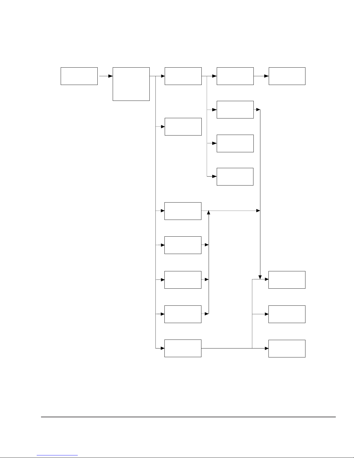
2-1. FLOW CHART
SECTION 2
DISASSEMBLY
REAR PANEL
P2-2
TOP COVER,
LEFT COVER,
RIGHT COVER,
TOP COVER
CHASSIS
P2-2
FRONT PANEL
ASS’Y
P2-3, P2-4
HDD
P2-4
VGA
CARD
P2-5
DRIVE COVER
ASS’Y
P2-8 P2-9
FDD
P2-9
CD-RW
P2-10
CNX-79
MOUNT
P2-10
DVD-ROM
IFX-90
ASS’Y
P2-5
MODEM
CARD
P2-6
SLOT
COVER
P2-6
POWER
SUPPLY
P2-7
MOTHER
BOARD
P2-11
CPU
P2-12, P2-13
MEMORY
(DIMM)
P2-13
•Ps-s denotes the page concerned.
• HDD has a low resistance to vibration, requiring careful handling.
2-1
PCV-R532DS/R536DS/R538DS/R539DS
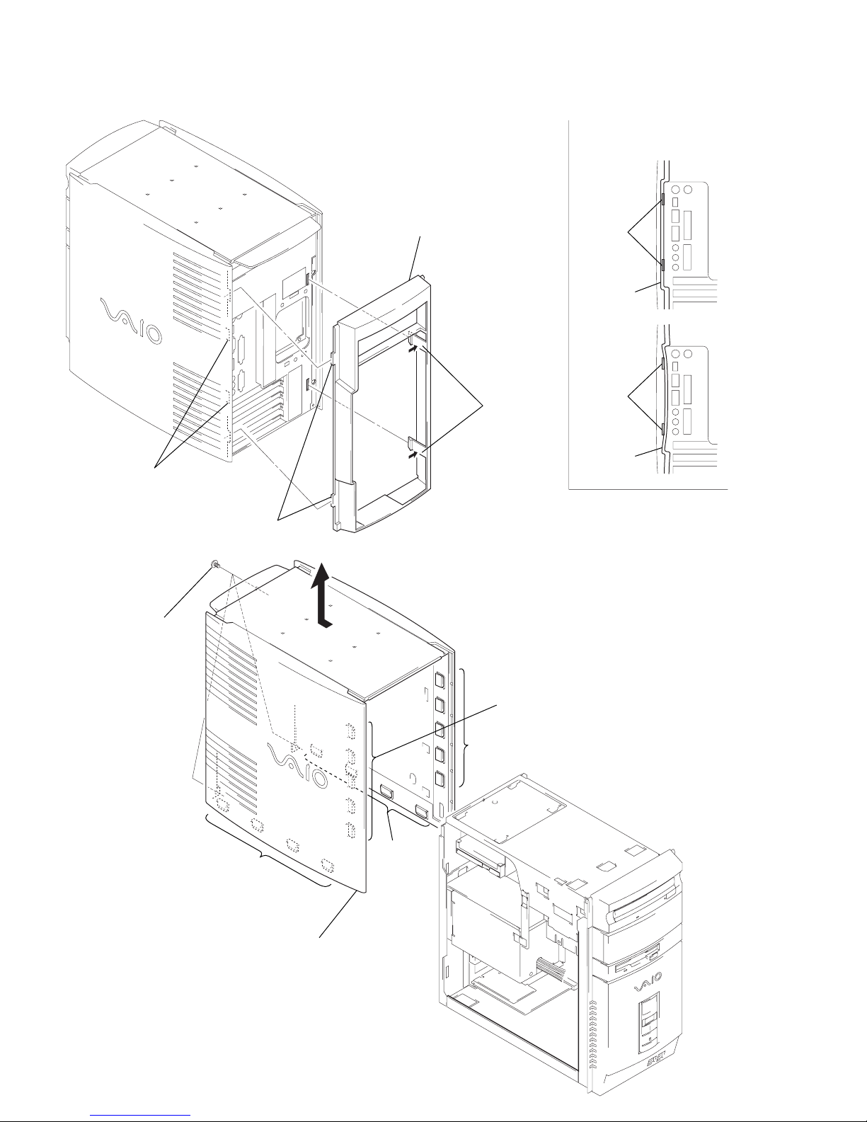
2-2. REAR PANEL
4
rear panel
Note on mounting rear panel:
When installation rear panel,
refer to figure.
GOOD
claws
rear panel
NG
1
two claws
rear panel
3
two claws
2
two claws
2-3. TOP COVER, LEFT COVER, RIGHT COVER AND TOP COVER CHASSIS
A
1
three screws
(unified 4.5)
2
five claws
2
five claws
claws
2
four claws
3
Remove top cover, left cover,
right cover and top cover
chassis in arrow
PCV-R532DS/R536DS/R538DS/R539DS
A
direction.
2
2-2
four
claws
s
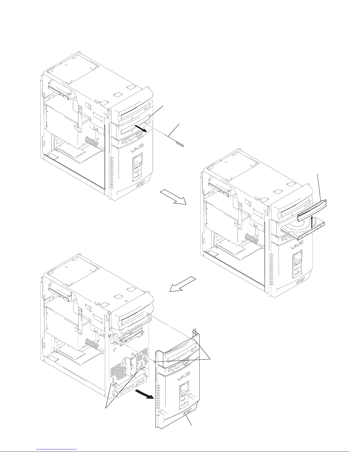
2-4. FRONT PANEL ASS’Y (PCV-R538DS/R539DS)
2
pull the disk tray.
1
Insert the pin.
3
escutcheon
4
two claws
2-3
5
6
front panel ass’y
two claw
PCV-R532DS/R536DS/R538DS/R539DS
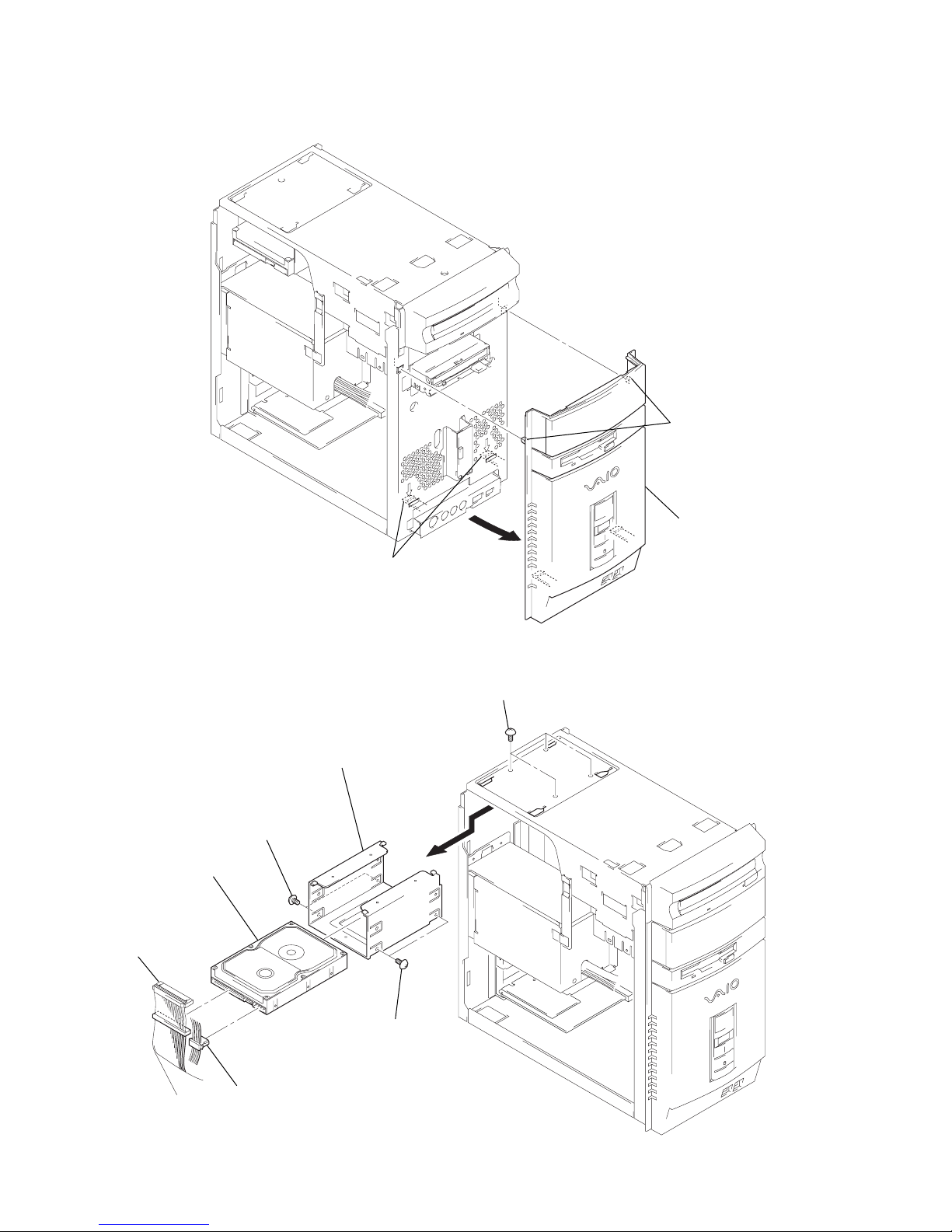
2-5. FRONT PANEL ASS’Y (PCV-R532DS/R536DS)
y
1
two claws
2
two claws
3
front panel ass’
2-6. HDD
2
harness
(IDE HDD)
6
5
HDD
4
Remove HDD and HDD
bracket in arrow A direction.
two screws
(No.6-32UNC)
1
power connector
5
two screws
(No.6-32UNC)
A
3
four screws
(unified 4.5)
PCV-R532DS/R536DS/R538DS/R539DS
2-4
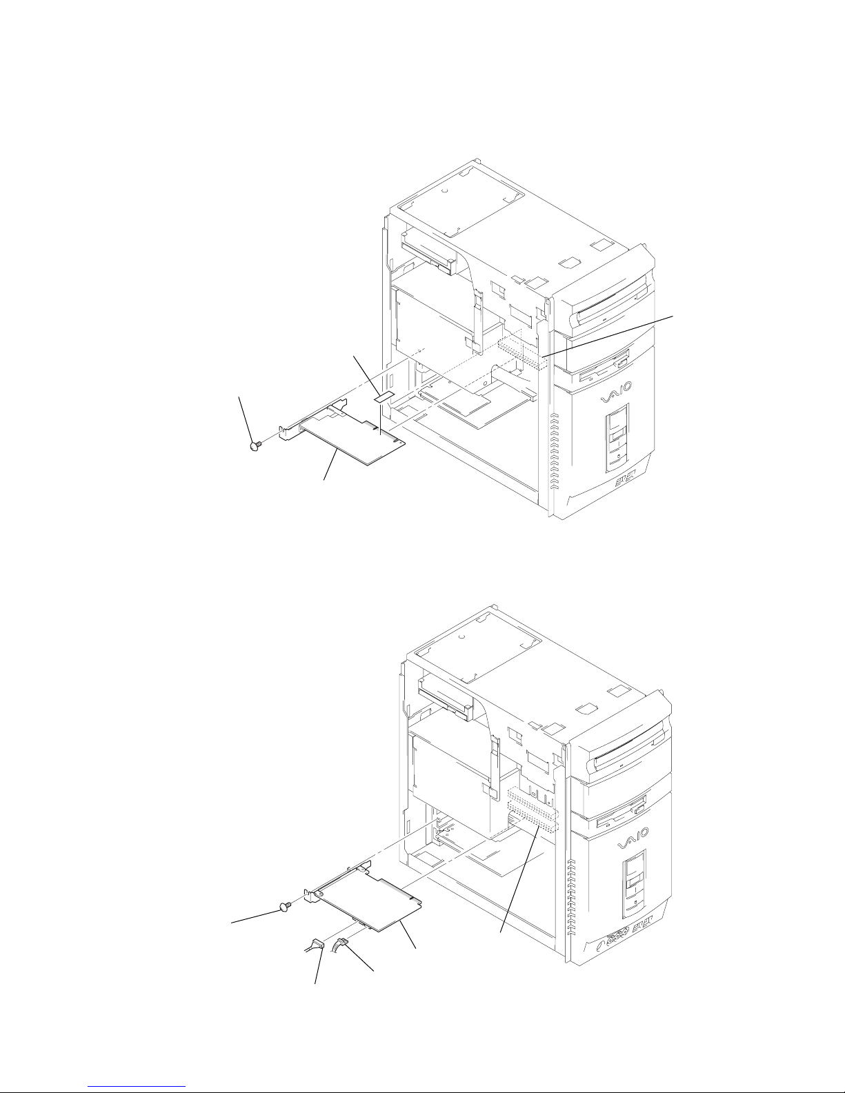
2-7. VGA CARD
P
(PCV-R536DS/R538DS/R539DS)
2
screw (unified 4.5)
1
AGP sheet
3
AG
VGA card
2-8. IFX-90 ASS’Y
(PCV-R532DS)
3
screw
(unified 4.5)
2
harness (1394)
4
IFX-90 ass’y
1
power connector
PC13
2-5
PCV-R532DS/R536DS/R538DS/R539DS

2-9. MODEM CARD
1
screw
(unified 4.5)
2
modem card
PCI 3 (PCV-R536DS/R538DS/R539DS)
PCI 4 (PCV-R532DS)
2-10. SLOT COVER
1
two screws
(unified 4.5)
2
two slot covers
PCV-R532DS/R536DS/R538DS/R539DS
2-6
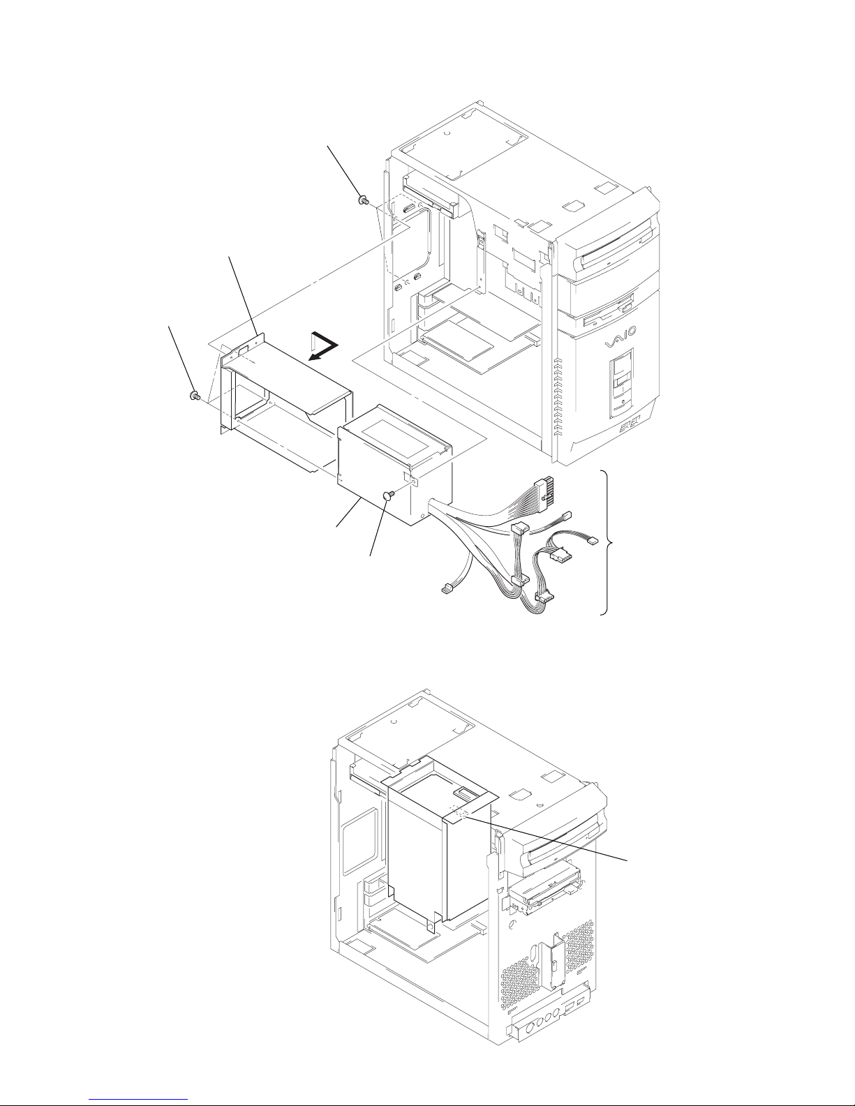
2-11. POWER SUPPLY
2
three screws
(PS No.6-32UNC)
4
three screws
(PS No.6-32UNC)
3
Remove power supply and
PS bracket ass’y
in arrow A direction.
A
5
power supply
2
screw
(unified 4.5)
1
Disconnect respective
power connectors
on the mother borad,
DVD-ROM,
CD-RW (PCV-R538DS/R539DS),
IFX-90 ass’y (PCV-R532DS),
FDD and HDD.
t
2-12. SERVICE POSITION
1
Remove power supply and PS bracket ass’y.
2
Hook the claw of PS bracke
ass’y on the chassis ass’y
2-7
PCV-R532DS/R536DS/R538DS/R539DS

2-13. DRIVE COVER ASS’Y
y
2
Pull the disk tray.
1
Insert the pin.
3
escutcheon ass’
5
drive cover ass’y
PCV-R532DS/R536DS/R538DS/R539DS
2-8
4
two claws
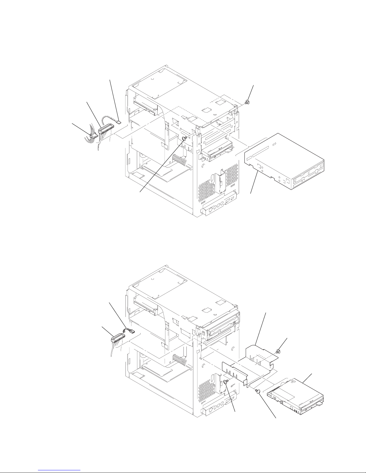
2-14. DVD-ROM
D
4
harness
(IDE CD/DVD)
3
power
connector
5
harness
(CD/DVD audio)
1
two screws
(PWH3
1
two screws
(PWH3
×
5)
2
×
5)
Pull the DVD-ROM.
6
Remove the DVD-ROM.
2-15. FDD
2
power connector
1
harness
(FDD)
5
two screws
(PWH3
4
FDD and
FDD bracket
5
two screws
×
6
5)
FD
(PWH3
×
5)
3
two screws
(unified 4.5)
2-9
PCV-R532DS/R536DS/R538DS/R539DS
 Loading...