

Sony VAIO PCV-L630 User Manual


ii
Notice to Users
© 2000 Sony Electronics Inc. All rights
reserved. This manual and the software
described herein, in whole or in part, may not
be reproduced, translated, or reduced to any
machine-readable form without prior written
approval.
SONY ELECTRONICS INC. PROVIDES NO
WARRANTY WITH REGARD TO THIS
MANUAL, THE SOFTWARE, OR OTHER
INFORMATION CONTAINED HEREIN
AND HEREBY EXPRESSLY DISCLAIMS
ANY IMPLIED WARRANTIES OF
MERCHANTABILITY OR FITNESS FOR
ANY PARTICULAR PURPOSE WITH
REGARD TO THIS MANUAL, THE
SOFTWARE, OR SUCH OTHER
INFORMATION. IN NO EVENT SHALL
SONY ELECTRONICS INC. BE LIABLE
FOR ANY INCIDENTAL,
CONSEQUENTIAL, OR SPECIAL
DAMAGES, WHETHER BASED ON TORT,
CONTRACT, OR OTHERWISE, ARISING
OUT OF OR IN CONNECTION WITH THIS
MANUAL, THE SOFTWARE, OR OTHER
INFORMATION CONTAINED HEREIN OR
THE USE THEREOF.
Sony Electronics Inc. reserves the right to
make any modification to this manual or the
information contained herein at any time
without notice. The software described
herein may also be governed by the terms of
a separate user license agreement.
Sony, VAIO, VAIO Slimtop, Memory Stick,
i.LINK, and the VAIO logo are trademarks of
Sony. Microsoft, Windows, and the Windows
98 logo are registered trademarks of
Microsoft Corporation. Intel and Pentium are
trademarks of Intel Corporation. K56flex is a
trademark of Lucent Technologies Inc. and
Rockwell International. All other trademarks
are trademarks of their respective owners.
Safety Information
Owner’s Record
The model number and serial number are
located on the back of your VAIO computer.
Record the serial number in the space
provided here. Refer to the model and serial
number when you call your Sony Service
Center.
Model Number: PCV-L630
Serial Number:________________________
WARNING
To prevent fire or shock hazard, do
❑
not expose your VAIO computer to
rain or moisture.
Never install modem or telephone
❑
wiring during a lightning storm.
Never install telephone jacks in wet
❑
locations unless the jack is specifically
designed for wet locations.
Never touch uninsulated telephone
❑
wire or terminals unless the telephone
line has been disconnected at the
network interface.
Use caution when installing or
❑
modifying telephone lines.
Avoid using the modem during an
❑
electrical storm.
Do not use the modem or a telephone
❑
to report a gas leak in the vicinity of
the leak.
!
The use of optical instruments
with this product will increase eye
hazard.
iii
VAIO Computer Reference Manual
For questions regarding your product, or for
the Sony Service Center nearest you, call:
1-888-476-6972
The phone number shown in the Declaration
of Conformity is for FCC-related matters
only.
Regulatory Information
Declaration of Conformity
Trade Name: SONY
Model No.: PCV-L630
Responsible Party: Sony Electronics Inc.
Address: 1 Sony Drive
Telephone: 201-930-6970
This device complies with Part 15 of FCC Rules.
Operation is subject to the two following
conditions:
(1) This device may not caus e harmful
interference, and
(2) this device must accept any interference
received, including interference that may cause
undesired operation.
This equipment has been tested and found to
comply with the limits for a Class B digital
device, pursuant to Part 15 of the Rules.
These limits are designed to provide
reasonable protection against harmful
interference in a residential installation. This
equipment generates, uses, and can radiate
radio frequency energy and, if not installed
and used in accordance with the instructions,
may cause harmful interference to radio
communications. However, there is no
guarantee that interference will not occur in a
particular installation. If this equipment does
cause harmful interference to radio or
television reception, which can be
determined by turning the equipment off
and on, the user is encouraged to try to
correct the interference by one or more of the
following measures:
Reorient or relocate the receiving
❑
antenna.
Increase the separation between the
❑
equipment and the receiver.
Park Ridge, NJ 07656
Connect the equipment into an outlet
❑
on a circuit different from that to
which the receiver is connected.
Consult the dealer or an experienced
❑
radio/TV technician for help.
You are cautioned that any changes or
modifications not expressly approved in this
manual could void your authority to operate
this equipment.
Only peripherals (computer input/output
devices, terminals, printers, etc.) that comply
with FCC Class B limits may be attached to
this computer product. Operation with noncompliant peripherals is likely to result in
interference to radio and television reception.
All cables used to connect peripherals must
be shielded and grounded. Operation with
cables, connected to peripherals, that are not
shielded and grounded, may result in
interference to radio and television reception.

iv
FCC Part 68
This equipment complies with Part 68 of the
FCC rules. The ringer equivalence number
(REN) and the FCC registration number are
printed on the modem board. If requested,
this information must be supplied to the
telephone company.
The REN is used to determine the quantity of
devices which may be connected to the
phone line. Excessive REN's on the telephone
line may result in the devices not ringing in
response to an incoming call. In most, but not
all areas, the sum of the REN's should not
exceed five (5.0). To be certain of the number
of devices that may be connected to the line,
as determined by the total REN's, contact the
telephone company to determine the
maximum REN for the calling area.
This modem uses the USOC RJ-11 telephone
jack.
If this equipment causes harm to the
telephone network, the telephone company
will, when practical, notify you in advance
that temporary discontinuance of service
may be required. If advance notice isn't
practical, the telephone company will notify
you as soon as possible. Also, you will be
advised of your right to file a complaint with
the FCC if you believe it is necessary.
The telephone company may make changes
in its facilities, equipment, operations or
procedures that could affect the operations of
the equipment. If this happens, the telephone
company will notify you in advance, in order
for you to make the necessary modifications
in order to maintain uninterrupted service.
If trouble is experienced with this modem,
for repair or warranty information, please
contact 1-888-4SONYPC, or write to the Sony
Customer Information Center, One Sony
Drive, Park Ridge, NJ 07656.
This equipment cannot be used on
telephone-company-provided coin service.
Connection to Party Line Service is subject to
state tariffs.
Repair of the modem should be made only
by a Sony Service Center or Sony authorized
agent. For the Sony Service Center nearest
you, call 1-800-222-SONY (1-800-222-7669).
Telephone Consumer Protection Act of 1991
The Telephone Consumer Protection Act of
1991 makes it unlawful for any person to use
a computer or other electronic device to send
any message via a telephone facsimile
machine unless such message clearly
contains, in a margin at the top or bottom of
each transmitted page or on the first page of
the transmission, the date and time it is sent
and an identification of the business, other
entity, or individual sending the message,
and the telephone number of the sending
machine or such business, other entity, or
individual.
In order to program this information into
your facsimile, see your fax software
documentation.
You are cautioned that any changes or
✍
modifications not expressly approved in
this manual could void your authority to
operate this equipment.

Contents
Notice to Users .................................................................................... ii
Safety Information .............................................................................. ii
Regulatory Information..................................................................... iii
FCC Part 68 ......................................................................................... iv
Telephone Consumer Protection Act of 1991................................. iv
Chapter 1 — Identifying Components
Front View .......................................................................................2
Drives ...................................................................................................3
Buttons and Switches .........................................................................4
Indicators ..............................................................................................5
Connectors ...........................................................................................6
Slots .......................................................................................................7
Rear View ......................................................................................... 8
I/O Connectors ....................................................................................9
Expansion Slot ....................................................................................12
Chapter 2 — Configuring Your System
Accessing the CMOS Setup Utility..............................................14
Changing the Display's Power Management Settings ............. 15
Configuring the System Board .................................................... 17
CMOS Jumper ....................................................................................17
CPU Frequency Ratio Multiplier Switches ....................................19
AGP_INT Switch................................................................................20
VGA Switch ........................................................................................21
v

vi
VAIO Computer Reference Manual
Chapter 3 — Removing, Installing, and Replacing
Components
Removing the System Cover .......................................................24
Replacing the System Cover ........................................................25
Installing an Add-In Card ............................................................26
Removing an Add-in Card ...........................................................27
Setting the Configuration Switches ............................................29
Setting the CMOS Jumper ............................................................30
Replacing the Lithium Battery .....................................................31
Installing System Memory ...........................................................34
Removing a Memory Module .....................................................36
Replacing the Hard Drive ...........................................................41
Removing a Slot Cover..................................................................44
Covering an Open I/O Slot ..........................................................45
Chapter 4 — System Board
Connectors ......................................................................................48
Front Panel Header............................................................................48
Diskette Drive (FLOPPY) Connector ..............................................49
IDE Connectors .................................................................................50
PCI Slot Connectors...........................................................................51
Memory Module (DIMM) Connectors ..........................................52
Power (ATX PWR) Connector .........................................................53
Fan (CPU FAN, CTRL PWR) Connectors ......................................54
Keyboard/Mouse (KB/MOUSE) Connector ................................55
USB Connectors .................................................................................56
PRINTER, SERIAL, and VGA MONITOR Connectors ...............57
LCD Connector ..................................................................................59
Wake On LAN (WOL_CON) Connector .......................................60
LINE IN and LINE OUT Connectors .............................................61
PHONE and MIC Connectors .........................................................62
Sony Memory Stick Slot Connector ................................................63
i.LINK Interface Header Connectors .............................................64
i.LINK Connectors ............................................................................65
Configuration Jumper and Switches ..........................................66
CMOS Jumper ...................................................................................66
Configuration Switches (SW)...........................................................67

Contents
Chapter 5 — Fax/Modem Card
Chapter 6 — CMOS Setup Options
STANDARD CMOS SETUP Screen ............................................ 74
BIOS FEATURES SETUP Screen..................................................75
CHIPSET FEATURES SETUP Screen.......................................... 78
POWER MANAGEMENT SETUP Screen..................................80
PNP AND PCI SETUP Screen .....................................................82
LOAD SETUP DEFAULTS Screen .............................................. 84
SUPERVISOR PASSWORD Screen ............................................. 84
USER PASSWORD Screen............................................................ 84
IDE HDD AUTO DETECTION Screen....................................... 84
SAVE & EXIT SETUP Screen........................................................84
EXIT WITHOUT SAVING Screen ...............................................84
Chapter 7 — Miscellaneous Technical Information
About User and Supervisor Passwords ..................................... 86
Beep Code Error Messages ..........................................................87
PCI Configuration Status and Error Messages ......................... 88
DMA Channel Assignments ....................................................... 89
IRQ Assignments ........................................................................ 90
System I/O Address Map .......................................................... 91
Memory Map ................................................................................. 93
vii
Chapter 8 — Specifications
Processor .......................................................................................95
Chipset ........................................................................................... 95
PCI Bus .......................................................................................... 95
Memory Modules (DIMMs) .......................................................95
DIMM Configurations .................................................................. 96
L2 Cache ......................................................................................... 96
Graphics ........................................................................................ 96
Audio ..............................................................................................97
Communications ..........................................................................97

viii
VAIO Computer Reference Manual
I/O and Expansion Slots .............................................................97
i.LINK Interface .............................................................................98
Drives and Controllers .................................................................98
System CMOS ...............................................................................98

Chapter 1
Identifying Components
The following sections identify and describe each component that is
visible from the exterior of the VAIO
identified in Chapters 3, 4, and 5 of this manual.
®
Computer. Internal components are
1
2
D
VAIO Computer Reference Manual
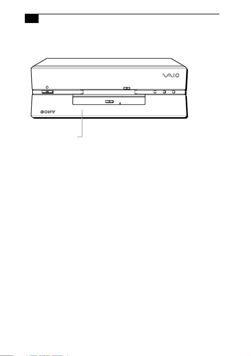
Front View
Flip-down panel
FD DISC HD
SHA0001.VS
Identifying Components
3
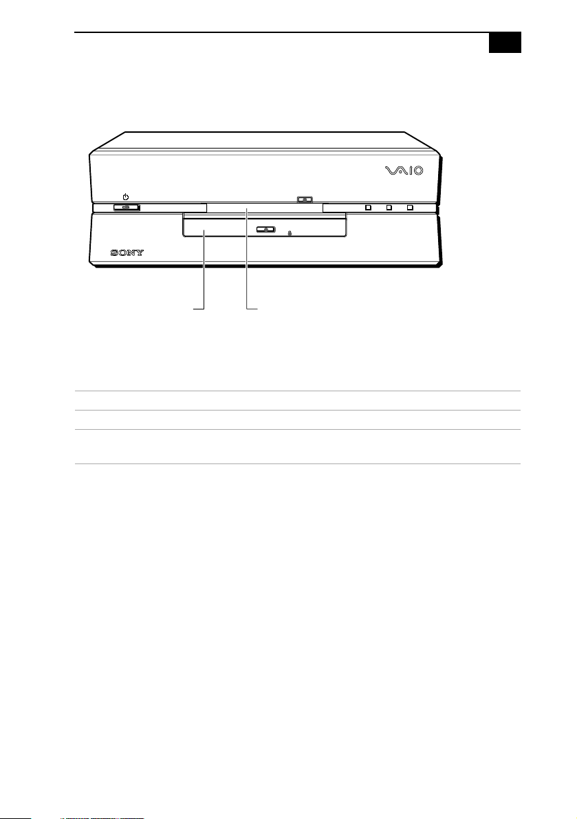
Drives
FD DISC HD
Floppy disk driveDVD-ROM disc drive
SHA0002.VSD
Drive Description
Diskette drive 3.5-inch, 1.44 Mbyte.
DVD-ROM drive
* Data on a DVD-ROM is read at a variable transfer rate, ranging from 2X at the innermost track to 4.8X at
the outermost track (the data transfer standard 1X rate is 1385 kbytes/s). The average data transfer rate
is 3.6X (4986 kbytes/s). Data on a CD-ROM is read at a variable transfer rate, ranging from 10.5X at the
innermost track to 24X at the outermost track (the data transfer standard 1X rate is 150 kbytes/s). The
average data transfer is 18X (2700 kbytes/s).
*
DVD-ROM disc read: 4.8X (maximum performance).
CD-ROM disc read: 24X (maximum performance).
4
VAIO Computer Reference Manual
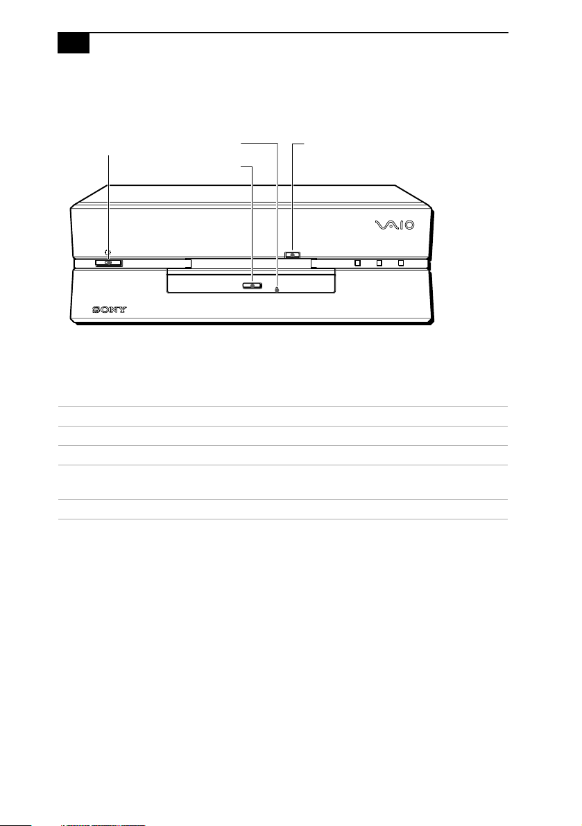
Buttons and Switches
Power on/off Floppy disk eject
Manual eject hole
DVD-ROM disc eject
FD DISC HD
Button or switch Description
Power/Standby switch Turns system power on and off.
Floppy disk eject button Ejects a diskette.
DVD-ROM disc eject
button
Automatically opens and closes the DVD-ROM
tray.
Emergency eject hole Ejects an optical disc.
SHA0003.VSD
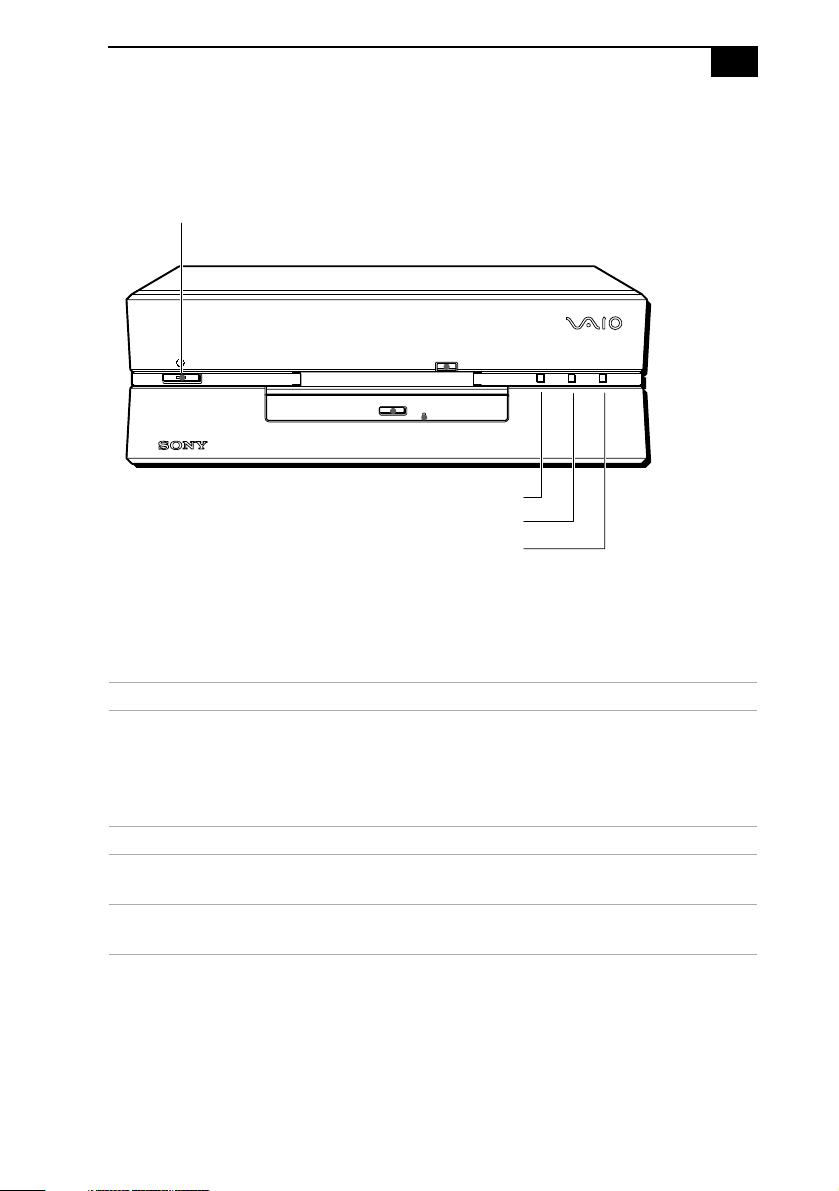
Indicators
Power on/off
Identifying Components
Diskette drive access indicator
DVD-ROM drive access indicator
Hard drive access indicator
5
FD DISC HD
SHA0004.VSD
Indicator Description
Power/Standby indicator Standby (amber) indicates the computer is in
standby mode. On (green) indicates the
computer is out of standby mode, ready to
use. Off (no color) indicates the computer is
turned off.
Diskette drive access indicator On (green) indicates diskette drive activity.
DVD-ROM drive access
On (orange) indicates optical disc activity.
indicator
Hard disk drive access
On (green) indicates hard disk drive activity.
indicator
6
D
VAIO Computer Reference Manual
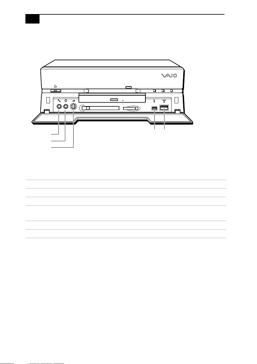
Connectors
FD DISC HD
MIC
PHONES
VOLUME
USBi.LINK
SHA0005.VS
Connector Description
MIC Connects to microphone.
PHONES Connects to headphones.
®
i.LINK
(IEEE-1394)
*
Connects to digital device that has a 4-pin i.LINK
connector.
USB Connects to USB devices.
VOLUME Controls headphone volume.
* To connect to a 6-pin i.LINK device, use the i.LINK connector on the back of the system. A 6-pin i.LINK
connector can supply power from the computer to the device if the device also has a 6-pin i.LINK conne ctor.
A 4-pin i.LINK connector cannot supply power to the device.
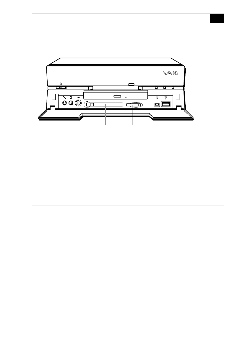
Slots
D
Identifying Components
FD DISC HD
7
PC Card
Slot
Memory Stick
Media Slot
SHA0006.VS
Slot Description
PC Card Slot Accommodates one Type I or Type II PCMCIA
card
Memory Stick
™
Media Slot Accommodates Memory Stick media
8
VAIO Computer Reference Manual
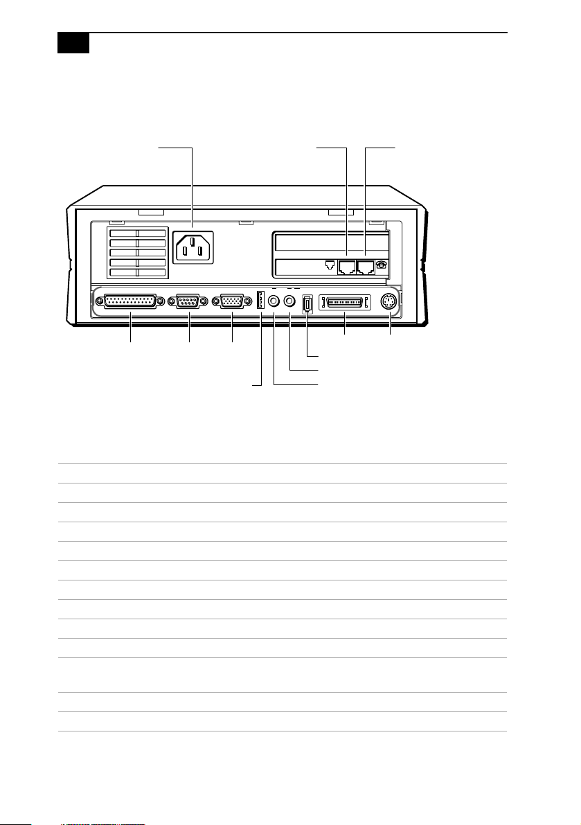
Rear View
Power LINE PHONE
PRINTER SERIAL MONITOR
PRINTER SERIAL MONITOR
USB LINE I.LINK
USB
OUTIN
LINE PHONE
S400
i.LINK
LINE OUT
LINE IN
LCD KEYBOARD
LCD
KEYBOARD
SHA0007.VSD
Connector Description
Power AC input power
LINE Connects to phone cable from wall jack
PHONE Connects to telephone
PRINTER Connects to parallel device
SERIAL Connects to serial device
MONITOR Connects to VGA monitor (optional)
USB Connects to USB devices
LINE IN Connects to output connector on audio device
LINE OUT Connects to input connector on audio device
i.LINK (IEEE-1394)
*
Connects to digital device that has a 6-pin i.LINK
connector
™
LCD Connects to VAIO Slimtop
LCD monitor
KEYBOARD Connects to keyboard
* To connect to a 6-pin i.LINK device, use the i.LINK connector on the back of the system. A 6-pin i.LINK
connector can supply power from the computer to the device if the device also has a 6-pin i.LINK
connector. A 4-pin i.LINK connector cannot supply power to the device.
Identifying Components
9
I/O Connectors
The following section identifies the various I/O connectors.
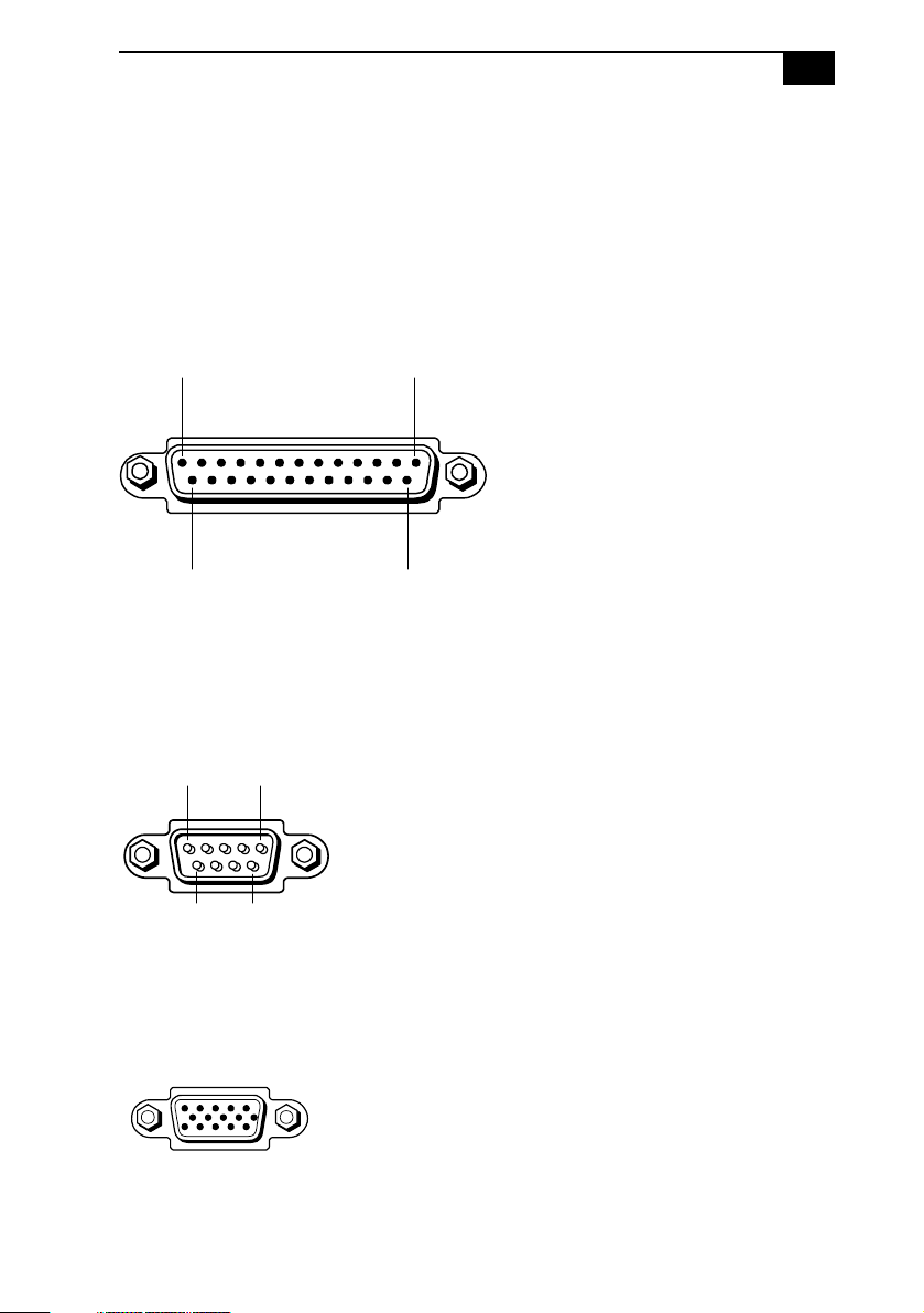
PRINTER Port
The PRINTER port is a standard 25-pin DB-25 female connector assigned
as LPT1.
13 1
25 14
KY0005.VSD
SERIAL Port
The SERIAL port is a standard 9-pin DB-9 male connector assigned as
COM1.
51
9
6
KY0057.VSD
MONITOR
The MONITOR connector is a standard 15-pin female high-density VGAtype connector.
SHA0009.VSD
10
D
VAIO Computer Reference Manual
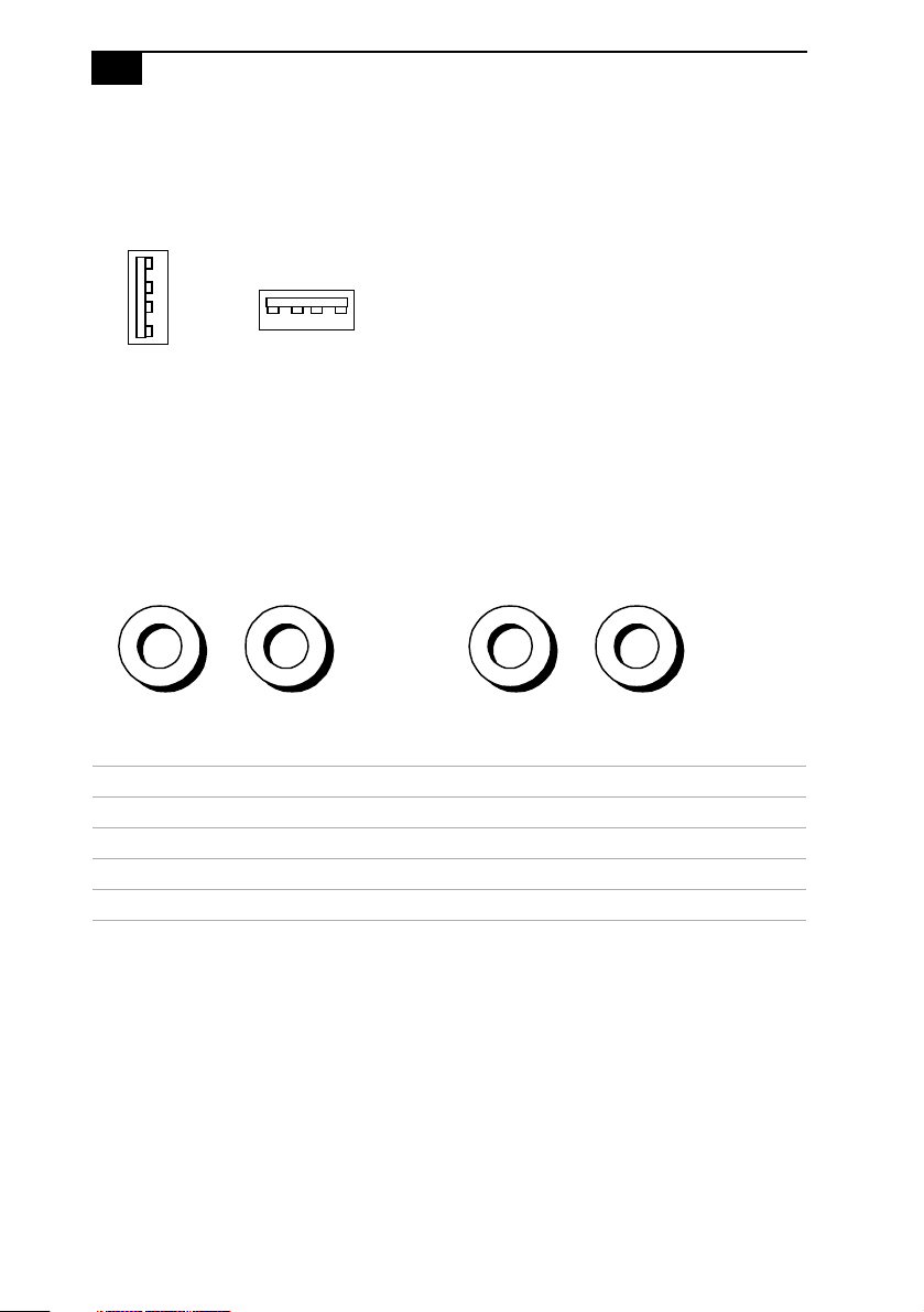
USB Connectors
A USB connector is located on the front and real panels.
Rear panel
Front panel
KY0003.VS
PHONE, MIC, LINE IN, and LINE OUT
The PHONES, MIC, LINE IN, and LINE OUT jacks are physically
identical, but have different connections. They are standard 3.5 mm stereo
mini-jacks. The PHONES and MIC jacks are located on the front panel.
The LINE IN and LINE OUT jacks are located on the rear panel.
PHONES MIC
Front panel
LINE IN LINE OUT
Rear panel
Connector Description
PHONES 1.0 Vrms output (typical) at 31 mW (32 ohm) output (max)
MIC Electrolet condenser microphone input
LINE IN 1.0 Vrms input (max), 50 Kohm impedance
LINE OUT 1.0 Vrms out (max)
KY0013.VSD
Identifying Components
D
11
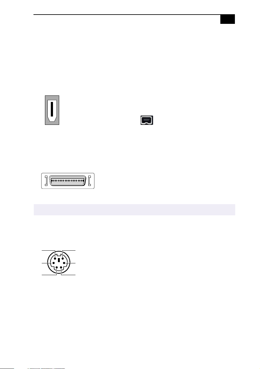
i.LINK (IEEE-1394)
The 6-pin i.LINK (IEEE-1394) connector on the rear panel can supply
power from the computer to a device if the device also has a 6-pin i.LINK
connector. The connector supplies 10V to 12V. The total power supplied
by the 6-pin i.LINK connector cannot exceed 6 watts.
6-pin i.LINK
(IEEE-1394)
4-pin i.LINK
(IEEE-1394)
On rear panel
On front panel
LCD
The LCD connector is a 40-pin female MDR-type connector.
Do not connect any LCD monitor other than the Sony VAIO Slimtop LCD monitor.
!
KEYBOARD/MOUSE
The KEYBOARD connector is a mini DIN-type female connector.
1
2 5
3
6
4
KY0087.VS
KY0004.VSD
KY0002.VSD
12
VAIO Computer Reference Manual
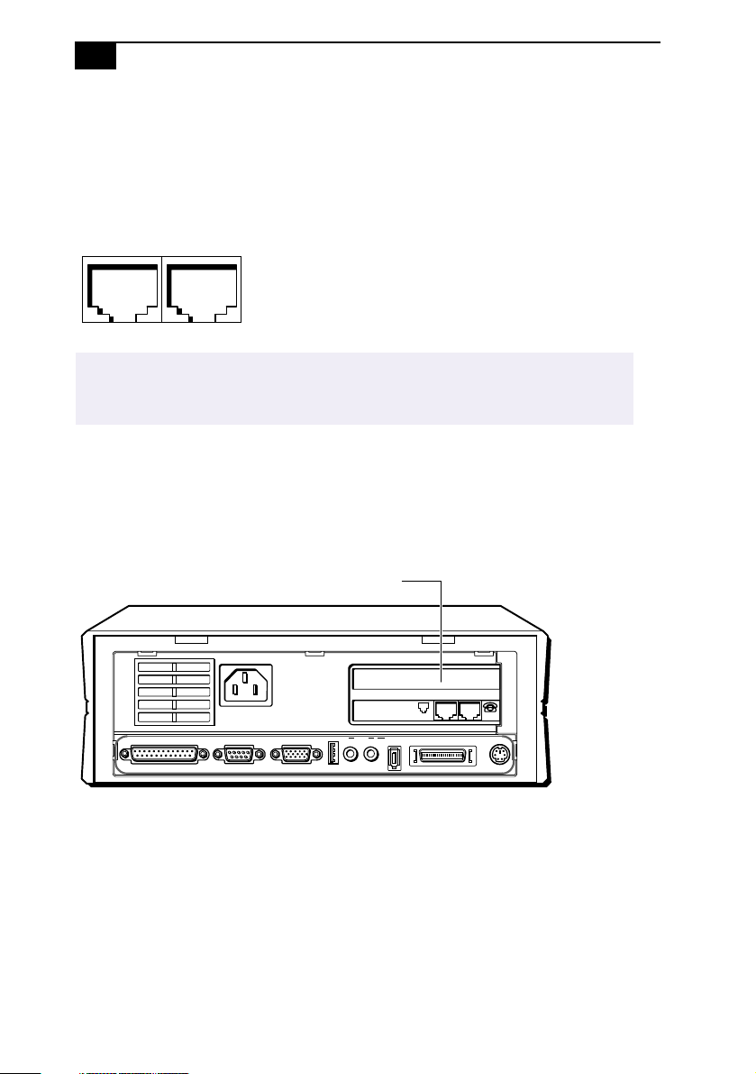
LINE and PHONE
The LINE and PHONE jacks are physically identical and have identical
connections. They are standard RJ-11 female phone jacks. However, the
LINE jack is for connecting to a telephone line that comes from the wall
jack, and the PHONE jack is for connecting the computer to a telephone.
LINE PHONE
KY0014.VSD
Accidentally plugging a phone line from the wall into the modem’s PHONE jack, and a
✍
telephone into the LINE jack, will not damage the modem card or telephone equipment.
However, the modem will not work correctly.
Expansion Slot
One PCI slot is available for expansion, except for some configure-toorder models, which may already use this slot. The other PCI slot is
occupied by the fax/modem card.
PCI Slot
PRINTER SERIAL MONITOR
USB LINE I.LINK
OUTIN
LINE PHONE
S400
LCD KEYBOARD
SHA0008.VSD

Chapter 2
Configuring Your System
This chapter contains information on configuring your system.
Configuring your system can consist of the following:
Making changes to the CMOS settings
❑
Making changes to the display's power management settings
❑
Changing the system board jumper position
❑
13

14
VAIO Computer Reference Manual
Accessing the CMOS Setup Utility
You must access the CMOS Setup Utility to make changes to the CMOS
settings (see “CMOS Setup Options” on page 73 for information on
CMOS settings).
Before rebooting the system, save any open files and exit Windows®.
!
Reboot the system. The following message appears during the initial
1
boot sequence:
Press TAB to show the POST screen, DEL to enter SETUP
Press DEL after the progress bar starts.
2
Use the arrow keys to select an item from the main menu.
3
Press Enter to display the options for the selected item.
4
Use the arrow keys to select an option.
5
Press Page Up or Page Down to modify the setting.
6
Press ESC to return to the main menu.
7
Select SAVE & EXIT SETUP, type Y, then press Enter. Follow the
8
onscreen prompts.
Configuring Your System
15
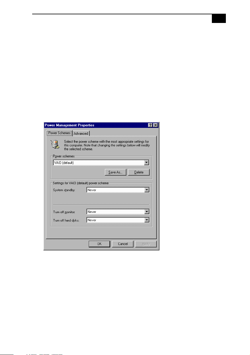
Changing the Display's Power Management Settings
A display that has power management capability is designed to operate
on reduced power or shut itself off after the system has been idle for a
specified period of time.
From the
1
Click the Power Management icon.
2
The Power Management Properties dialog box opens, with the
Power Schemes tab displayed.
Start
menu, point to Settings, then click Control Panel.
Select the power scheme that is most appropriate for the way you use
3
your computer.
To change a power scheme, change the settings for System standby,
Tur n o ff m o ni to r, an d Tu rn of f h ar d d i s ks .
The System standby option allows you to specify the period of
inactivity (in minutes) that you want to elapse before your computer
goes on standby when your computer is running on AC power.
Power is reactivated when you move the mouse or press a key.
The Turn off monitor option allows you to specify the period of
16
VAIO Computer Reference Manual
inactivity (in minutes) that you want to elapse before your monitor
turns off when your computer is running on AC power. The display
reactivates when you move the mouse or press a key.
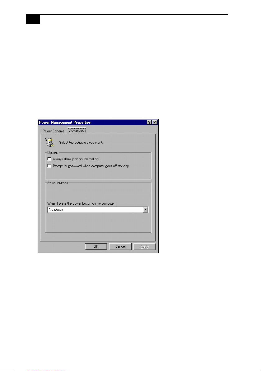
The Turn off hard disks option allows you to specify the period of
inactivity (in minutes) that you want to elapse before your hard disks
turn off when your computer is running on AC power.
To save a new power scheme, first modify the settings, click
4
type a descriptive name, and then click
Click the Advanced tab.
5
Select the desired settings, and then click OK.
6
OK
.
Save As
,

Configuring Your System
17
Configuring the System Board
The system board contains the following configuration settings:
CMOS jumper
❑
CPU Multiplier switches
❑
AGP_INT switch
❑
VGA switch
❑
The configuration jumpers should never need changing unless otherwise directed by a
✍
technical support or service technician.
!
Before opening the system, save any open files, exit Windows, turn off the
power of the computer and all attached peripherals, and unplug the
power cord.
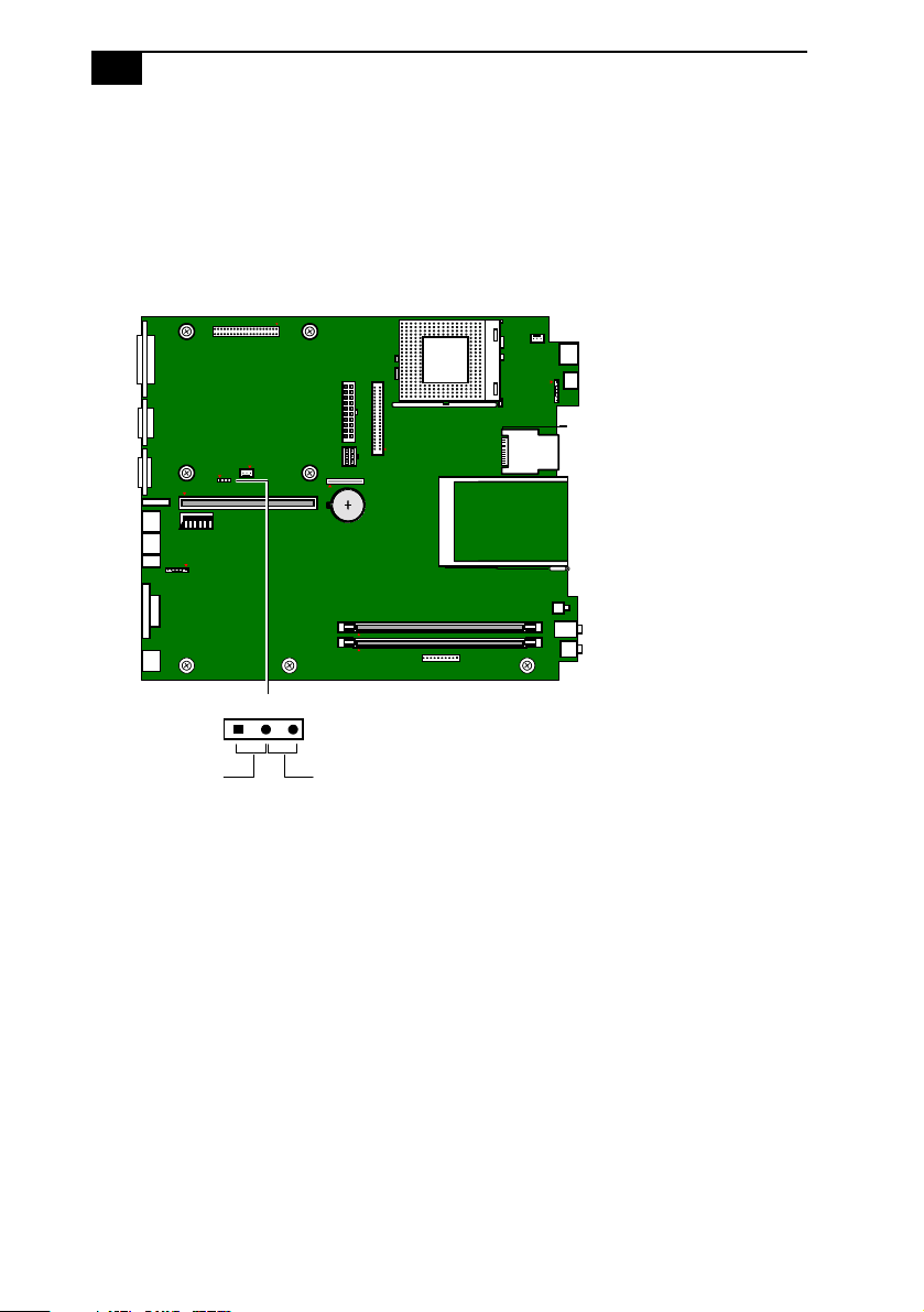
CMOS Jumper
The CMOS jumper provides two modes of operation: Normal mode, and
Clear CMOS mode.
Normal mode allows normal access to the BIOS Setup Utility. The Central
Processing Unit (CPU) input clock is forced to remain at 100 MHz (fast
mode), and the Basic Input/Output System (BIOS) uses the User CMOS
settings (as opposed to the System CMOS settings). The CMOS and
NVRAM settings are only cleared if the checksum test returns false.
Access to specific setup fields is controlled by a supervisor password or
user password.
The Clear CMOS mode removes the password that is stored in CMOS. No
other parameters are cleared.
18
VAIO Computer Reference Manual
To change the CMOS jumper, perform the following steps:
Remove the system cover (see “Removing the System Cover” on
1
page 24).
Set the jumper as directed by a service technician (also see “CMOS
2
Jumper” on page 66).
123456
O
N
123
CMOS ClearNormal
Reinstall the system cover (see “Replacing the System Cover” on
3
page 25).
KY
Configuring Your System
D
19
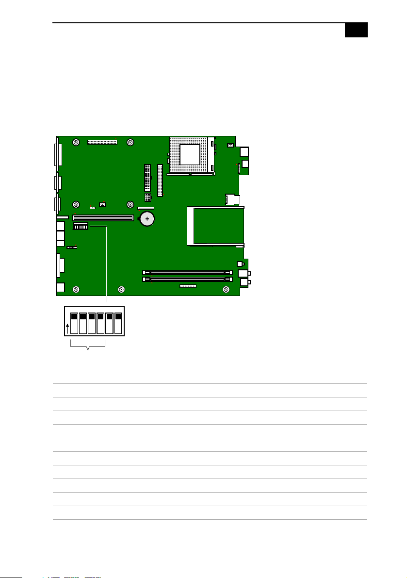
CPU Frequency Ratio Multiplier Switches
The computer ships with the FREQ Ratio multiplier set to X6.0 (see SW
table for positions of SW 1 through 4). Changing the FREQ Ratio
multiplier will not change the speed of your CPU. Do not change the
position of any switch unless directed by a technical support person.
123456
O
N
SW
123456
O
N
ON
OFF
FREQ Ratio
MAN006.VS
SW
FREQ Ratio SW 1 SW 2 SW 3 SW 4
X3.0 ON OFF ON ON
X3.5 OFF OFF ON ON
X4.0 ON ON OFF ON
X4.5 OFF ON OFF ON
X5.0 ON OFF OFF ON
X5.5 OFF OFF OFF ON
X6.0 (default)ONONONOFF
X6.5 OFFONONOFF
X7.0 ON OFF ON OFF
20
D
VAIO Computer Reference Manual
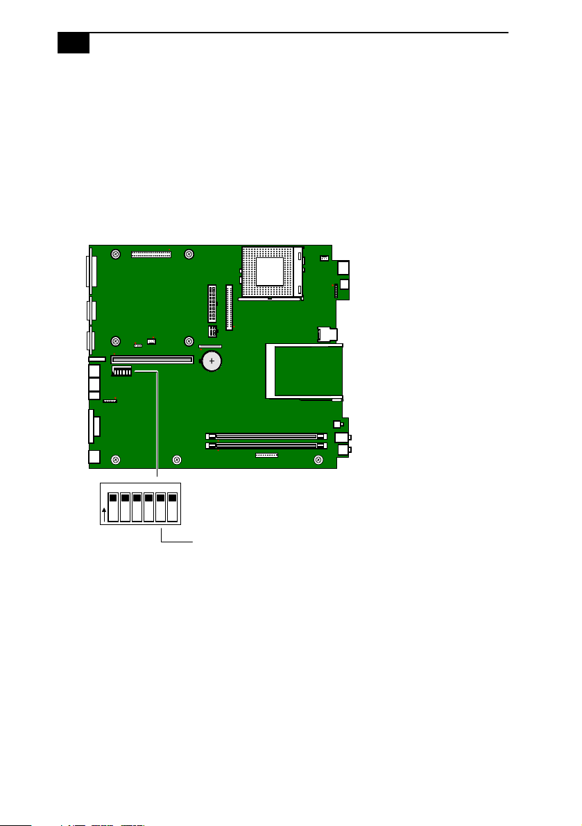
AGP_INT Switch
You can enable or disable the onboard AGP interrupt.
To enable or disable the AGP_INT, perform the following steps:
Remove the system cover (see “Removing the System Cover” on
1
page 24).
Set the switch to ON (Enable) or OFF (Disable). The default is ON
2
(see also “Configuration Switches (SW)” on page 67).
123456
O
N
SW
123456
O
N
Reinstall the system cover (see “Replacing the System Cover” on
3
ON
OFF
AGP_INT switch
page 25).
KY0093.VS
Configuring Your System
D
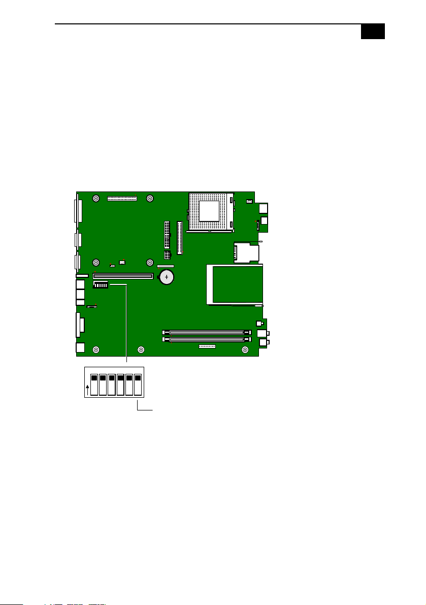
VGA Switch
You can enable or disable the onboard VGA controller if you install a
VGA PCI add-in card.
To enable or disable the onboard VGA, perform the following steps:
Remove the system cover (see “Removing the System Cover” on
1
page 24).
Set the VGA switch (SW6) to ON (Enable) or OFF (Disable). The
2
default is ON (also see “Configuration Switches (SW)” on page 67).
123456
O
N
21
SW
123456
O
N
Reinstall the system cover (see “Replacing the System Cover” on
3
ON
OFF
VGA switch
page 25).
KY0092.VS

22
 Loading...