

Sony VAIO PCV-J150 Service Manual

PCV-J150
SERVICE MANUAL
Ver 3-2005B
Revision History
Specifications
US Model
Canadian Model
S400
9-928-398-13
PERSONAL COMPUTER VAIO
CAUTION
Danger of explosion if battery is incorrectly replaced.
Replace only with the same or equivalent type
recommended by the manufacturer.
Dispose of used batteries according
to the manufacturer’s instructions.
Confidential
PCV-J150 (UC)
– 2 –

TABLE OF CONTENTS
1. OPERATION
2. DISASSEMBLY
2-1. Flow Chart.................................................................... 2-1
2-2. Main Electric Parts Arrangement ................................ 2-1
2-3. L Side Plate Ass’y........................................................ 2-2
2-4. Front Panel Ass’y......................................................... 2-2
2-5. Slot Cover..................................................................... 2-3
2-6. Ethernet Card ............................................................... 2-3
2-7. Modem Card (PCI)....................................................... 2-4
2-8. HDD ............................................................................. 2-4
2-9. Switching Power .......................................................... 2-5
2-10. CD-RW......................................................................... 2-5
2-11. FDD .............................................................................. 2-6
2-12. Memory (DIMM) ......................................................... 2-7
2-13. CPU .............................................................................. 2-7
2-14. Mother Board ............................................................... 2-8
3. MOTHER BOARD DESCRIPTION
3-1. A7S-AV Mother Board ................................................ 3-1
4. PROGRAMS FOR SERVICE
4-1. General Description ..................................................... 4-1
4-2. PC-Doctor Starting Method ......................................... 4-1
4-3. SiS VIDEO Diagnostics ............................................... 4-1
5. SERVICE INFORMATION
5-1. Jumper Setting on Hard Disk Drive ............................ 5-1
5-2. Jumper Setting of Main Board..................................... 5-2
6. FRAME HARNESS
6-1. Connector List.............................................................. 6-1
6-2. Frame Harness Diagram .............................................. 6-5
7. REPAIR PARTS LIST
7-1. Exploded View and Parts List...................................... 7-1
7-2. Accessories and Parts List ........................................... 7-4
– 3 –
Confidential
PCV-J150 (UC)

2-1. FLOW CHART
SECTION 2
DISASSEMBLY
L SIDE
PLATE
ASS’Y
P2-2
FRONT
PANEL
ASS’Y
P2-2
SLOT
COVER
P2-3
ETHERNET
CARD
P2-3
MODEM
CARD
(PCI)
P2-4
HDD
P2-4
SWITCHING
POWER
P2-5
CD-RW
P2-5
FDD
P2-6
MEMORY
(DIMM)
P2-7
CPU
P2-7
MOTHER
BOARD
P2-8
• Ps-s denotes the page concerned.
• HDD has a low resistance to vibration, requiring careful handling.
2-2. MAIN ELECTRIC PARTS ARRANGEMENT
mother board
switching power
CPU
memory (DIMM)
CD-RW
FDD
ethernet card
modem card (PCI)
HDD
2-1
Confidential
PCV-J150 (UC)
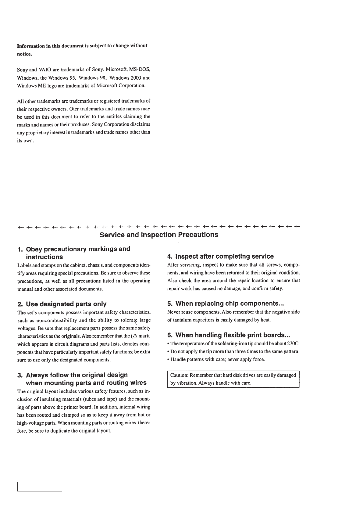
2-3. L SIDE PLATE ASS’Y
1
ornamental screw
Remove the L side plate ass’y
2
in the direction of arrow
A
A
.
2-4. FRONT PANEL ASS’Y
A
3
two claws
Remove the front
4
panel ass’y in the
direction of arrow
A
.
Confidential
2
two claws
1
1
2-2PCV-J150 (UC)
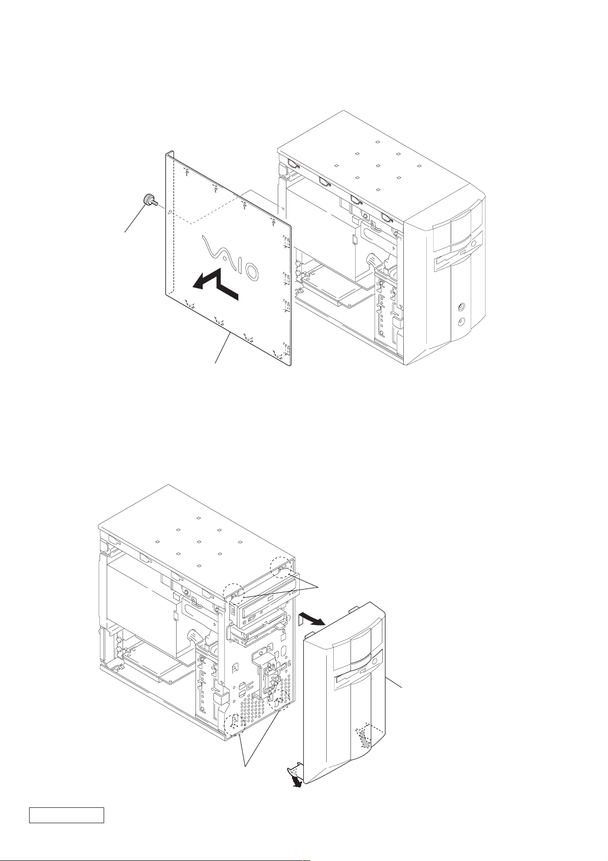
2-5. SLOT COVER
1
two screws
(No.6-32UNC)
2
two slot covers
2-6. ETHERNET CARD
1
screw
(No.6-32UNC)
2
ethernet card
PCI3
2-3
Confidential
PCV-J150 (UC)
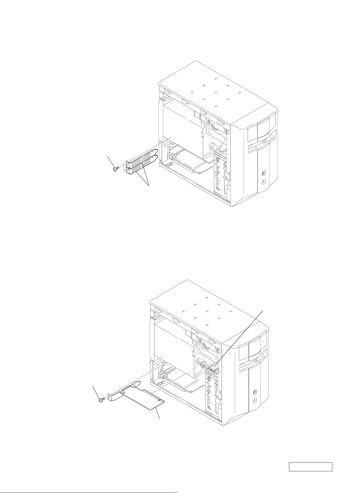
2-7. MODEM CARD (PCI)
1
screw
(No.6-32UNC)
PCI4
2-8. HDD
1
power connector
6
two screws
(No.6-32UNC)
7
HDD
2
2
harness
(HDD)
modem card
4
four claws
6
two screws
(No.6-32UNC)
Confidential
A
5
Remove HDD and HDD holder
in the direction of arrow A.
2-4PCV-J150 (UC)
3
lever
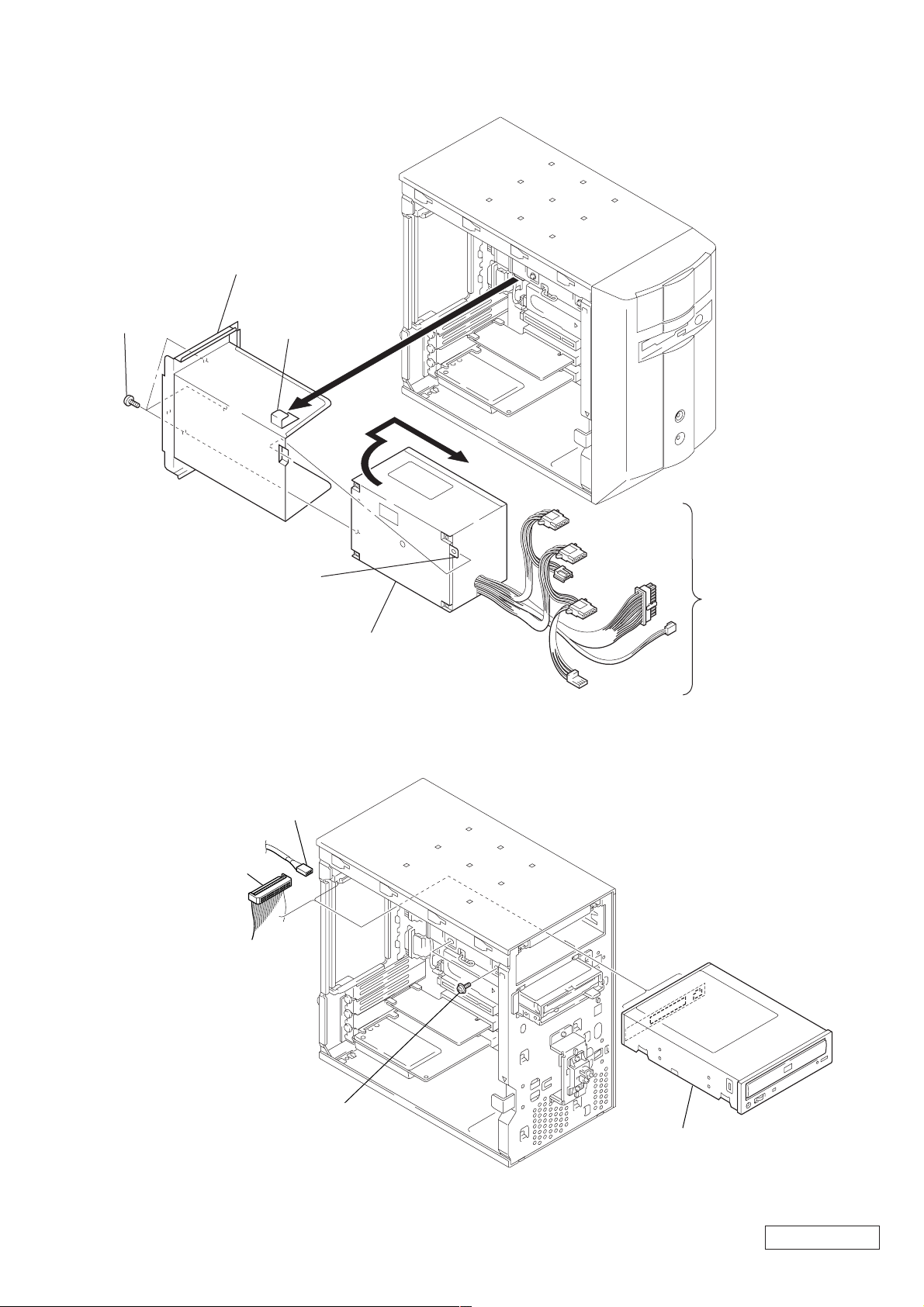
2-9. SWITCHING POWER
2
Remove switching power
and SPS bracket
in the direction of arrow A.
4
three screws
(No. 6-32UNC)
1
claw
A
B
2-10. CD-RW
1
harness
(IDE/CD-ROM)
6
Remove the switching power
in the direction of arrow
2
harness
(CD-ROM/AUDIO)
5
claw
B
3
Disconnect respective
power connectors on the
mother board, CD-RW, FDD,
.
and HDD.
3
two screws
(PWH3
×
5)
4
Remove the CD-RW.
Confidential
2-5
PCV-J150 (UC)
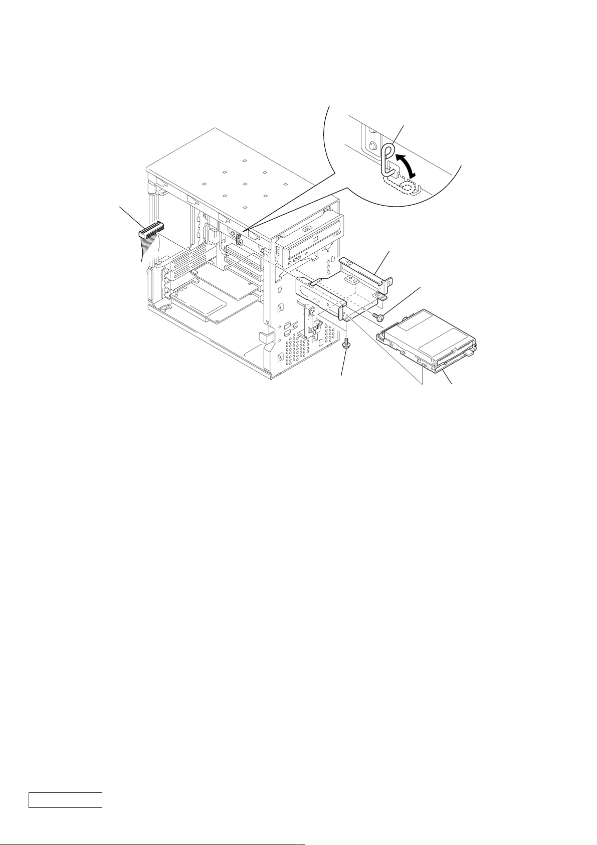
2-11. FDD
1
harness
(FDD)
3
4
FDD holder
lever
2
screw
(No.6-32UNC)
5
four screws
(PWH3 × 5)
6
FDD
Confidential
2-6PCV-J150 (UC)
 Loading...