

Sony VAIO PCV-E314DS Service Manual
PCV-E314DS
SERVICE MANUAL
Specifications
US Model
REVISED
9-928-304-12
PERSONAL COMPUTER VAIO
PCV-E314DS
–2 –

TABLE OF CONTENTS
1. OPERATION ................................................................ 1-1
2. DISASSEMBLY
2-1. Flow Chart........................................................................ 2-1
2-2. Side Cover (L).................................................................. 2-2
2-3. Escutcheon (DVD) ........................................................... 2-2
2-4. Front Panel Ass’y (H) ...................................................... 2-3
2-5. Top Cover ......................................................................... 2-3
2-6. FDD Bracket and FDD .................................................... 2-4
2-7. HDD Bracket and HDD ................................................... 2-4
2-8. PS Bracket Ass’y and Pow er Supply ............................... 2-5
2-9. DVD-ROM Ass’y............................................................. 2-5
2-10. Wiring Route .................................................................... 2-6
2-11. IFX-57/Y Ass’y ................................................................ 2-6
2-12. IFX-61 Ass’y .................................................................... 2-7
2-13. Modem Card (PCI/U) ...................................................... 2-7
2-14. I/O Shield (For Slot) ........................................................ 2-8
2-15. Switch/LED Ass’y............................................................ 2-8
2-16. CNX-54 Ass’y .................................................................. 2-9
2-17. CPU and Heat Sink ........................................................ 2-10
Heat Sink Installation..................................................... 2-10
2-18. Memory (DIMM) ........................................................... 2-11
Memory (DIMM) Installation........................................ 2-11
2-19. Main Board..................................................................... 2-12
2-20. Main Electric Pats Arrangement.................................... 2-12
3. DR736 MOTHERBOARD DESCRIPTION
3-1. Overview .......................................................................... 3-1
3-2. Form Factor ...................................................................... 3-1
3-3. Manufacturing Options .................................................... 3-1
3-4. Connectors and Headers .................................................. 3-1
3-5. BIOS ................................................................................. 3-1
3-6. Floppy Drive Support....................................................... 3-1
3-7. CD-ROM/DVD-ROM Drive Support .............................. 3-1
3-8. IDE Drive Support ........................................................... 3-1
3-9. Main Memory................................................................... 3-1
3-10. PCI Audio ......................................................................... 3-2
3-11. AGP Graphics .................................................................. 3-2
3-12. Battery Requirements ...................................................... 3-2
3-13. Other Key Components.................................................... 3-2
3-14. Thermal Consideration .................................................... 3-2
3-15. Power Supply/Consumption ............................................ 3-2
3-16. Regulatory Compliance ................................................... 3-2
4. SERVICE INFORMATION
4-1. Jumper Setting on Hard Disk Drive ................................ 4-1
4-2. Jumper Setting of Main Board......................................... 4-2
5. FRAME HARNESS
5-1. Connector List .................................................................. 5-1
5-2. Frame Harness Diagram .................................................. 5-7
6. REPAIR PARTS LIST
6-1. Exploded view and Parts List .......................................... 6-1
6-2. Accessories and Parts List ............................................... 6-3
6-3. BarCord Label .................................................................. 6-4
– 3 –
PCV-E314DS

SECTION 1
OPERATION
Reproduced from User
Guide [4-641-377-01]
1-1
PCV-E314DS
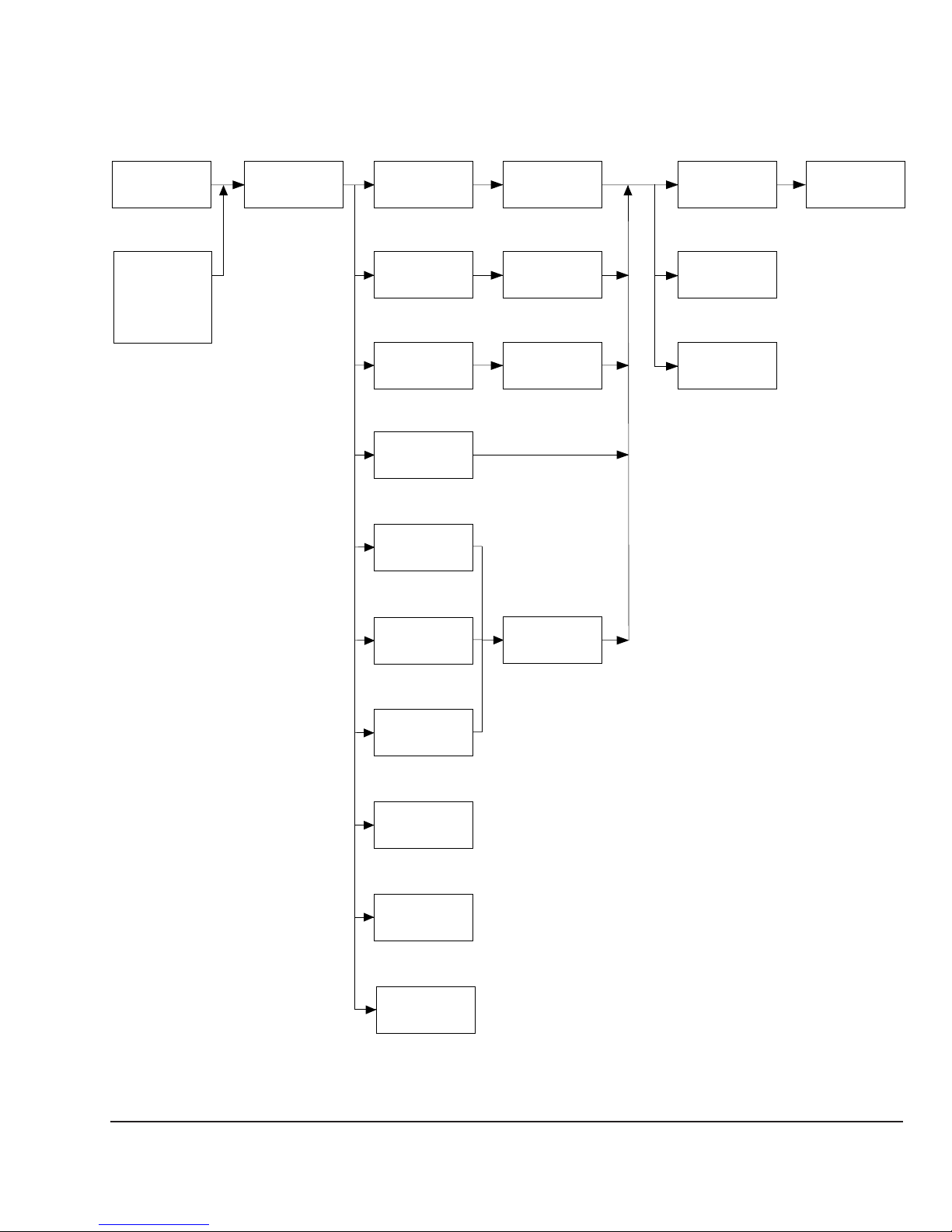
2-1. FLOW CHART
SECTION 2
DISASSEMBLY
SIDE
COVER (L)
P2-2
ESCUTCHEON
(DVD)
AND
ESCUTCHEON
HOLDER
P2-2
FRONT PANEL
ASS’Y (H)
P2-3
FDD
BRACKET
P2-4
HDD
BRACKET
P2-4
PS BRACKET
ASS’Y
P2-5
DVD-ROM
ASS’Y
P2-5
IFX-57/Y
ASS’Y
P2-6
FDD
P2-4
HDD
P2-4
POWER
SUPPLY
P2-5
CPU
P2-10
MEMORY
P2-11
MAIN
BOARD
P2-12
HEAT SINK
P2-10
IFX-61
ASS’Y
P2-7
MODEM CARD
P2-7
TOP
COVER
P2-3
SWITCH/LED
ASS’Y
P2-8
CNX-54
ASS’Y
P2-9
I / O SHIELD
(FOR SLOT)
P2-8
•Pπ-π denotes the page concerned.
• HDD has a low resistance to vibration, requiring careful handling.
2-1
PCV-E314DS
2-2. SIDE COVER (L)
1
2
three claws
3
Remove the side
cover (L) to direction
of the arrow A.
two ornamental
screws
A
2
three claws
2-3. ESCUTCHEON (DVD) AND ESCUTCHEON HOLDER
5
claw
6
three claws
7
A
1
Insert the clip.
Remove the
escutcheon
holder to
direction of
the arrow
A
.
PCV-E314DS
2-2
4
escutcheon (DVD)
2
Pull the disk tray.
3
two claws
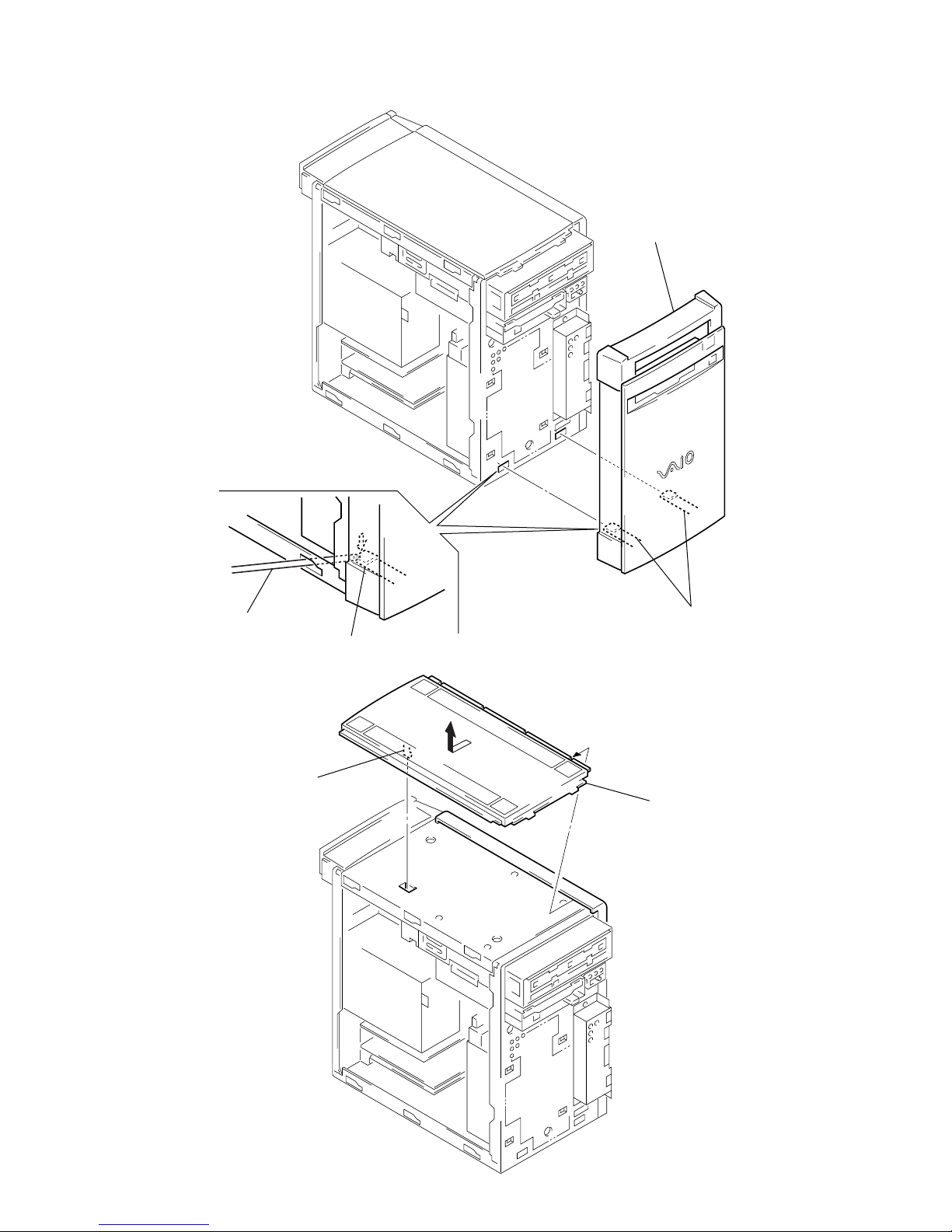
2-4. FRONT PANEL ASS’Y (H)
2
front panel ass’y
long-nose screwdriver.
2-5. TOP COVER
1
claw
claw
A
1
Remove two claws
by long-nose screw driver.
2
Remove the top cover
to direction of the arrow
A
.
2-3
PCV-E314DS
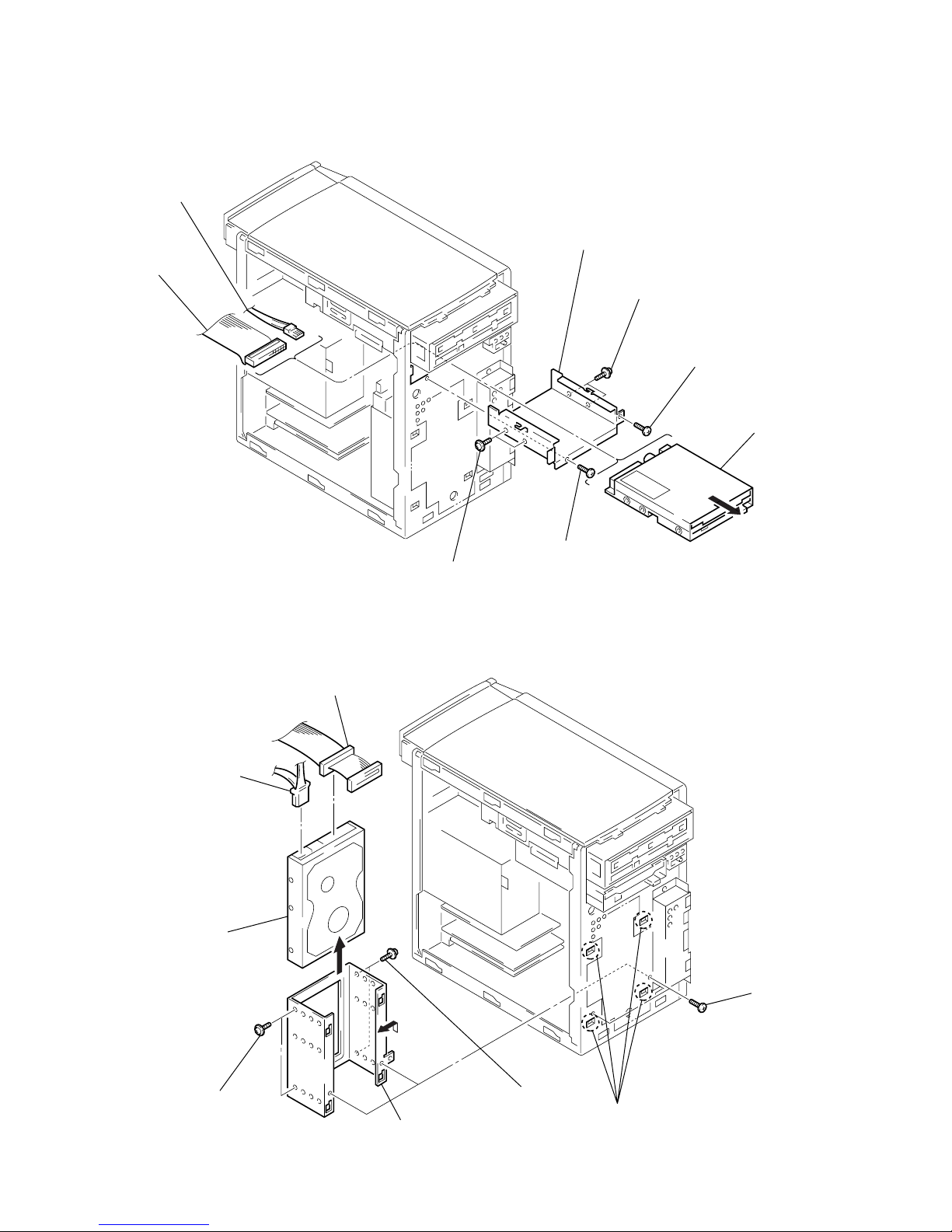
2-6. FDD BRACKET AND FDD
D
s
2
power cable
1
harness
(FDD)
5
two screws (PWH3 × 5)
4
FDD bracket
3
screw (P3 × 5)
5
two screws (P3 × 5)
3
screw (P3 × 5)
6
FD
2-7. HDD BRACKET AND HDD
• HDD has a low resistance to vibration, requiring careful handling.
1
power cable
7
6
HDD
two screws
2
harness
(IDE HDD)
A
5
Remove the HDD
bracket to direction
of the arrow
A
.
6
two screws
4
four claws
3
two screw
PCV-E314DS
2-4

2-8. PS BRACKET ASS’Y AND POWER SUPPLY
1
three screws
3
Remove the PS bracket
ass’y to direction of the
arrow A.
A
D
C
2
three claws
5
three screws
(P3 × 5)
6
Remove the power supply
to order of arrow B – D.
2-9. DVD-ROM ASS’Y
3
harness
(CD/DVD AUDIO)
1
harness
(IDE CD/DVD)
B
4
Disconnect respective power connectors on the
main board, CD-R, FDD, HDD, and IFX-61 ass’y.
1
power cable
4
two screws
(PWH3
5
DVD-ROM ass’y
×
5)
2-5
PCV-E314DS

2-10. WIRING ROUTE
harness (USB)
harness (1394)
cable clamp
i.Link
USB
2-11. IFX-57/Y ASS’Y
3
screws
×
5)
(P3
2
harness (SPDIF)
4
IFX-57/Y ass’y
1
harness (SER2)
PCV-E314DS
2-6
 Loading...