

Sony VAIO PCG-XE7 Service Manual
Confidential
Sony Corporation
Information Technology Company
9-872-093-41
PCG-XE7 (I)
This manual and the constituent data may not be
replicated, copied nor reprinted in whole or in part
without prior written authorization of Sony Corporation.
English
2000G1605-1
© 2000 Sony Corporation
Printed in U.S.A.
VAIO Customer Link (JAPAN)
PCG-XE7
International Model
SERVICE MANUAL
NOTEBOOK COMPUTER
9-872-093-41
S400
PCG-XE7 (I)
9-872-093-41
2000G1605-1
— 2 —
PCG-XE7 (I)
Information in this document is subject to change without notice.
Sony and VAIO are trademarks of Sony . Intel logo and Intel Inside
logo are registered trademarks of Intel Corporation. Pentium MMX
is a trademark of Intel Corporation. Microsoft, MS-DOS, Windo ws,
the W indows 95 and W indows 98 log o are trademarks of Microsoft
Corporation.
All other trademarks are trademarks or registered trademarks of
their respective owners. Other tr ademarks and trade names may be
used in this document to refer to the entities claiming the marks and
names or their products. Sony Corporation disclaims any proprietary
interest in trademarks and trade names other than its own.
Service and Inspection Precautions
1. Obey precautionary markings and instructions
Labels and stamps on the cabinet, chassis, and components identify areas
requiring special precautions. Be sure to observe these precautions, as well
as all precautions listed in the operating manual and other associated
documents.
2. Use designated parts only
The set’s components possess important safety characteristics, such as
noncombustibility and the ability to tolerate large voltages. Be sure that
replacement parts possess the same safety characteristics as the originals.
Also remember that the 0 mark, which appears in circuit diagrams and
parts lists, denotes components that have particularly important safety
functions; be extra sure to use only the designated components.
3. Always follow the original design when mounting
parts and routing wires
The original layout includes various safety features, such as inclusion of
insulating materials (tubes and tape) and the mounting of parts above the
printer board. In addition, internal wiring has been routed and clamped so
as to keep it away from hot or high-voltage parts. When mounting parts or
routing wires, therefore, be sure to duplicate the original layout.
4. Inspect after completing service
After servicing, inspect to make sure that all screws, components, and wiring
have been returned to their original condition. Also check the area around
the repair location to ensure that repair work has caused no damage, and
confirm safety.
5. When replacing chip components...
Never reuse components. Also remember that the negati ve side of tantalum
capacitors is easily damaged by heat.
6. When handling flexible print boards...
•The temperature of the soldering-iron tip should be about 270C.
•Do not apply the tip more than three times to the same pattern.
•Handle patterns with care; never apply force.
Caution: Remember that hard disk drives are easily damaged by
vibration. Always handle with care.
Caution Markings for Lithium/Ion Battery - The following or similar
texts shall be provided on battery pack of equipment or in both the
operating and the service instructions.
CAUTION: Danger of explosion if battery is incorrectly replaced.
Replace only with the same or equivalent type recommended by
the manufacturer. Discard used batteries according to the
manufacturer’s instructions.
CAUTION: The battery pack used in this de vice may present a fire
or chemical burn hazard if mistreated. Do not disassemble, heat
above 100°C (212°F) or incinerate.
Dispose of used battery promptly.
Keep away from children.
CAUTION: Changing the back up battery.
• Overcharging, short circuiting, reverse charging, multilation or
incineration of the cells must be avoided to prevent one or mor e of
the following occurrences; release of toxic materials, release of
hydrogen and/or oxygen gas, rise in surface temperature.
• If a cell has leaked or vented, it should be replaced immediately.
Use protection when handling battery.
ATTENTION AU COMPOSANT AYANT RAPPORT
À LA SÉCURITÉ!
LES COMPOSANTS IDENTIFÉS P AR UNE MARQUE 0 SUR LES
DIAGRAMMES SCHÉMA TIQUES ET LA LISTE DES PIÈCES SONT
CRITIQUES POUR LA SÉCURITÉ DE FONCTIONNEMENT. NE
REMPLACER CES COMPOSANTS QUE PAR DES PIÈSES SONY
DONT LES NUMÉROS SONT DONNÉS DANS CE MANUEL OU
DANS LES SUPPÉMENTS PUBLIÉS PAR SONY.
Confidential

TABLE OF CONTENTS
CHAPTER 1. REMOVAL
1-1. Flowchart ......................................................................... 1-1
1-2. Main Electrical Parts Location Diagram ......................... 1-1
1-3. Removal........................................................................... 1-2
1. Hinge Cover ..................................................................... 1-2
2. Keyboard Unit..................................................................1-2
3. HDD Assy ........................................................................ 1-3
4. Hou Flap Assy, Flap Base Plate....................................... 1-3
5. Hou Palmrest Assy, Display Base, IFX-70 Board ........... 1-4
6. Display Assy .................................................................... 1-4
7. MBX-25 Board Assy (1)..................................................1-5
8. Speaker Assy, V/L Richargeable Battery,
CNX-75 Board, ANL-17 Board.......................................1-5
9. MBX-25 Board Assy (2)..................................................1-6
10.Flash Panel, Bezel Housing Assy .................................... 1-7
11.LCD Unit, Inverter Assy, LCD Flexible Print ................. 1-8
(to 1-8)
CHAPTER 2. SELF DIAGNOSTICS
2-1. Required Tools and Peripheral Devices ........................... 2-1
2-2. Tools and Peripheral Device Connection.........................2-3
2-3. Starting up the Service Diagnostics ................................. 2-4
2-4. Outline of Service Diagnostics Functions ....................... 2-4
(to 2-6)
CHAPTER 3. BLOCK DIAGRAM............................... 3-1
(to 3-2)
CHAPTER 4. FRAME HARNESS DIAGRAM........ 4-1
(to 4-2)
CHAPTER 5. EXPLODED VIEWS AND
PARTS LIST
............................................ 5-1
5-1. Main Section.................................................................... 5-2
5-2. LCD Section
– Made by HI – .......................................... 5-5
(to 5-6)
Section Title Page
PCG-XE7 (I)
Confidential
— 3 —
APPENDIX
CHAPTER 1. SPECIFICATIONS..................................1-1
CHAPTER 2. OVERVIEW
2-1. Locating Controls and Connectors ....................................2-1
CHAPTER 3. SERVICE INFORMATION
3-1. Install Procedure after the Hard Disk is Replaced.............3-1
1-1 PCG-XE7 (I)
Confidential
CHAPTER 1.
REMOVAL
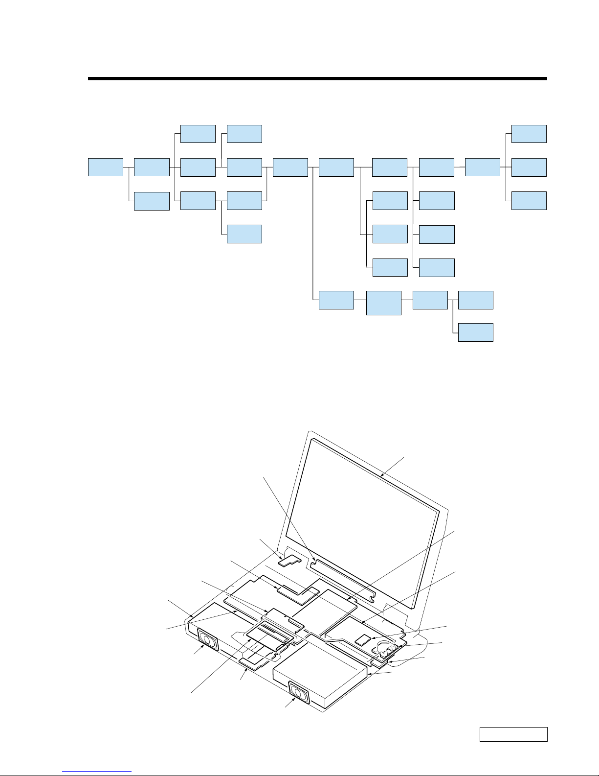
1-1. Flowchart
• P XX refers to page numbers that appear in this manual.
• Remember that hard disk drives are easily damaged by vibration. Always handle with care.
1-2. Main Electrical Parts Location Diagram
LCD Unit
Inverter Assy
CNX-74 board
Battery Pack
CNX-75 board
IFX-70 board
ANL-17 board
FD Drive
or
CD-RW Drive
or
Battery Pack Weight Saver
RO-31 board
HDD
CPU Module
MBX-25 board
Touch Pad
Speaker
Speaker
PWS-7 board
SO-DIMM
POWER
OFF
FDD
CD-R
BATTERY
PACK
P 1-7
P 1-7
P 1-8
P 1-8
P 1-8
P 1-4
DISPLAY
ASSY
P 1-5
HEAT
SINK U
P 1-5
MBX-25
ASSY (1)
BEZEL
HOUSING
ASSY
LCD
UNIT
INVERTER
ASSY
FLASH
PANEL
LCD
CABLE
P 1-2
P 1-2
P 1-3
KEY BOARD
UNIT
HOU FLAP
ASSY
HINGE
COVER
DC FAN
P 1-6
P 1-6
P 1-6
CPU
CNX-74
BOARD
PWS-7
BOARD
P 1-6
P 1-4
HOU PALM
REST
FLAP BASE
PLATE
SO-DIMM
P 1-3
P 1-3
HDD
P 1-5
P 1-5
P 1-5
LITHIUM
BATTERY
CNX-75
BOARD
SPEAKER
ASSY
P 1-6 P 1-6
I/O
BRACKET
P 1-6
P 1-6
RO-31
BOARD
PC CARD
CONNECTOR
P 1-6
MBX-25
BOARD
1-2PCG-XE7 (I)
Confidential
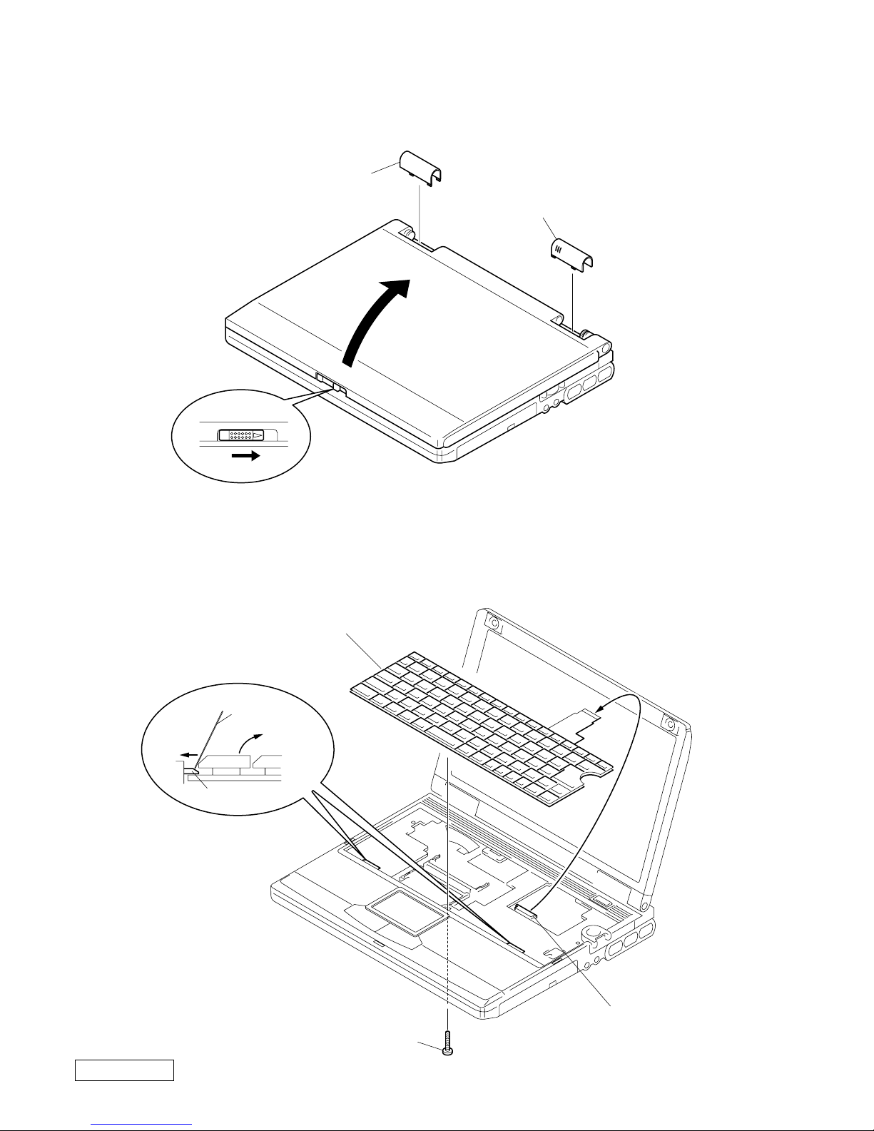
1-3.Removal
1. Hinge Cover
2. Keyboard Unit
1 Hinge Cover (L)
1 Hinge Cover (R)
2
3
1 0-Number P3 Kind
Screw (M2)
2
3
4
Keyboard Unit
Latch (Key)
MBX-25 board
CN902
5
Clip or the
like
1-3 PCG-XE7 (I)
Confidential
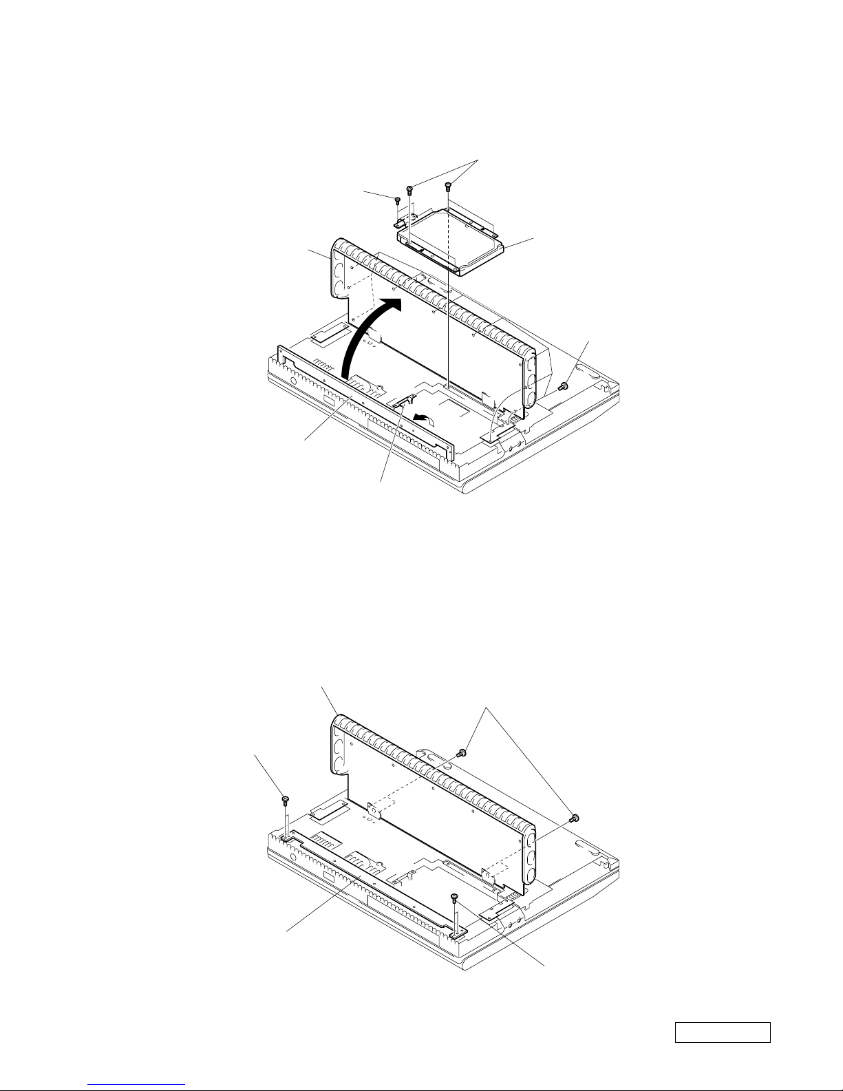
3. HDD Assy
4. Hou Flap Assy, Flap Base Plate
1 Special Head
Screws (x9)
2
4
3
5
6
HDD Assy
Hou Flap Assy
Special Head
Screws
+B M2
(X4)
(X2)
MBX-25 board CN1101
Flap Base Plate
4
Flap Base Plate
1 Special Head Screws (M2) (x4)
3 Special Head
Screws (M2) (x2)
3 Special Head Screws (M2) (x2)
2 Hou Flap Assy
1-4PCG-XE7 (I)
Confidential
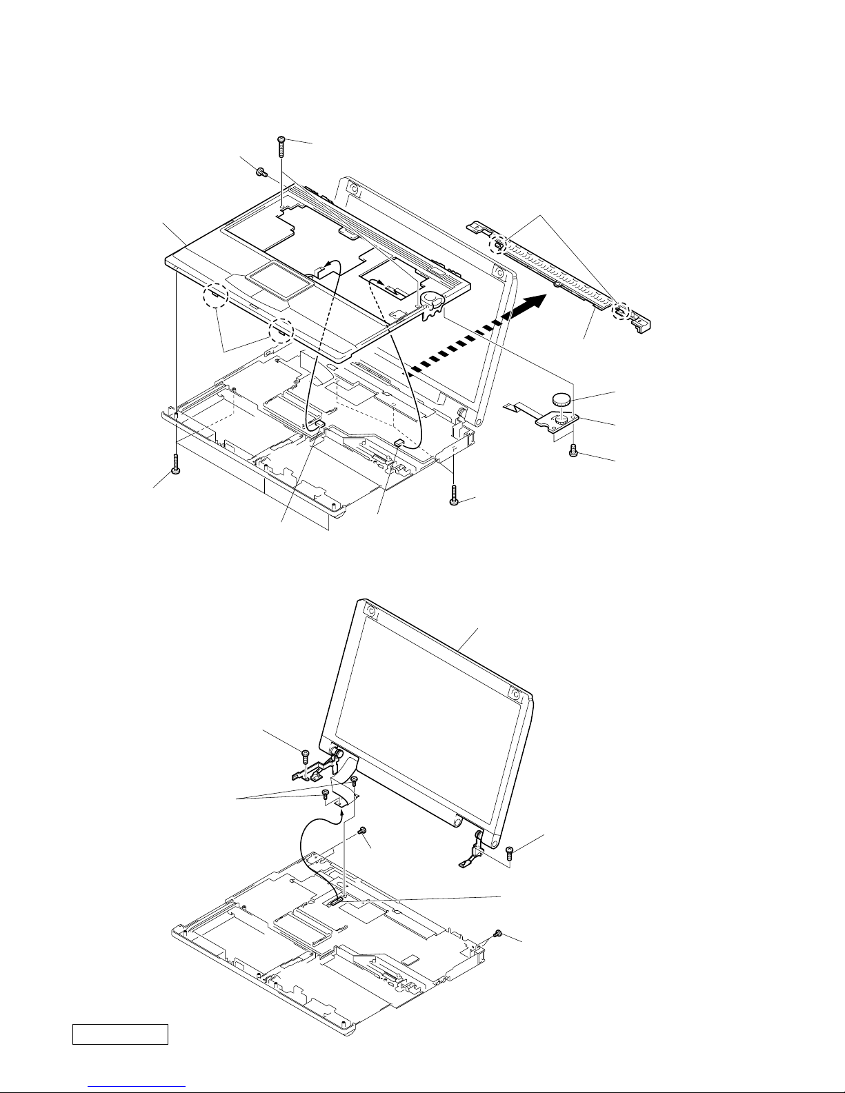
5. Hou Palmrest Assy, Display Base, IFX-70 Board
6. Display Assy
4 Special Head
Screw (M3)
6
5 Claws
2 0-number P3 Kind
Screw (M2) (X4)
2 0-number P3 Kind
Screw (M2) (X3)
3 +P 2x12 (X2)
1
1
qa Display Base
7 +B M2 (X2)
Hou Palmrest Assy
MBX-25 board
CN901
MBX-25 board
CN903
0 Claws
8 IFX-70 board
9 Dial
1 Special Head
Screws
4 Special Head
Screws (M2) (X2)
Display Assy
4 Special Head
Screws (M2) (X2)
3 +B M2
3 +B M2
5
2
(M2) (X2)
MBX-25 board CN301
1-5 PCG-XE7 (I)
Confidential
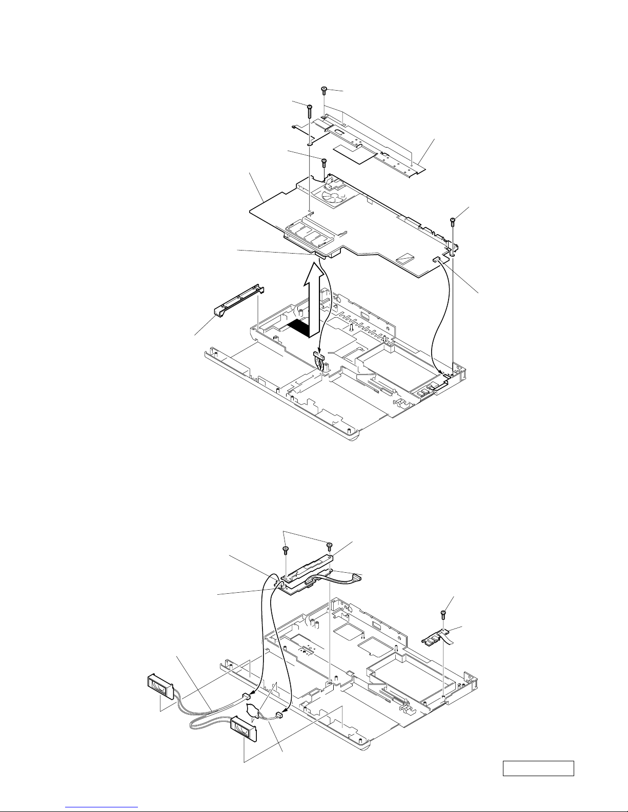
7. MBX-25 Board Assy (1)
8. Speaker Assy, V/L Rechargeable Battery, CNX-75 Board, ANL-17 Board
1 Special Head Screws (M2) (X3)
2 +B2x12
5 +B M2
MBX-25 Board Assy
5 +B M2
3 Heat Sink U
4
9
7
6
8 Cover (FFC)
MBX-25 board
CN1501
MBX-25 board
CN551
5 +B M2 (X2)
8 +B M2
9 ANL-17 board
7 CNX-75 board
1
3
2 Speaker Assy
4 V/L Rechargeable Battery
CNX-75 board
CN6006
CNX-75 board
CN6005
Cover (BATT)
6
1-6PCG-XE7 (I)
Confidential
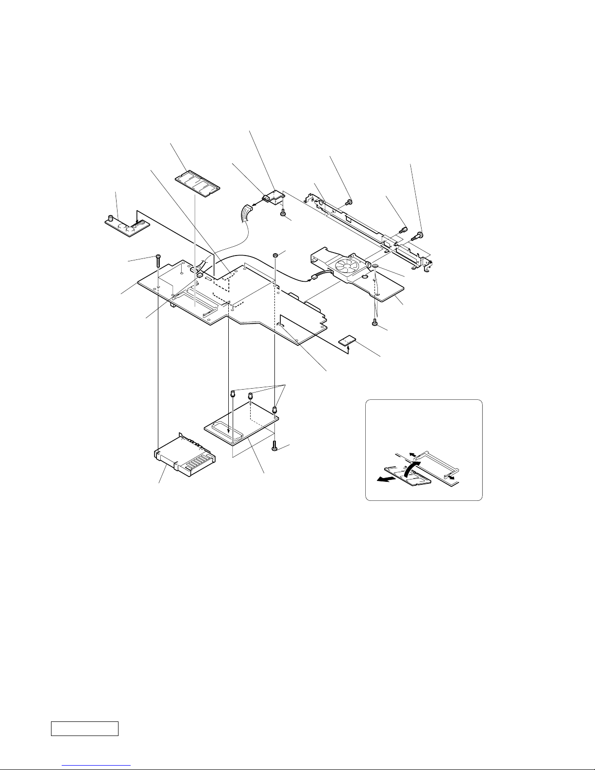
9. MBX-25 Board Assy (2)
B
C
A
A
A → C
Order of releasing
the SO-DIMM
7 CNX-74 board
6 Special Head
Screw (M2) (X2)
5 I/O Bracket
3 Screw
(HEX) (X2)
2 Screws (Supplied) (X2)
qa
q; DC Fan
9 Special Head
Screw (M2) (X2)
qd RO-31 board
qs
MBX-25 board CN751
MBX-25 board CN1301
qj Screw
(M2) (X3)
ql CPU Module
qj PC Card (Ejector) Connector
MBX-25 board
CN 1102
ws MBX-25 board
qh +B2X12 (x3)
qg PWS-7 board
SO-DIMM
qk Nu+M2 (3)
qf
CNX-74 board
CN 5001
1
8
4 ACE (M2), Lock
wa Stand
Off (X3)
w;
Washer
P3 (X2)
1-7 PCG-XE7 (I)
Confidential
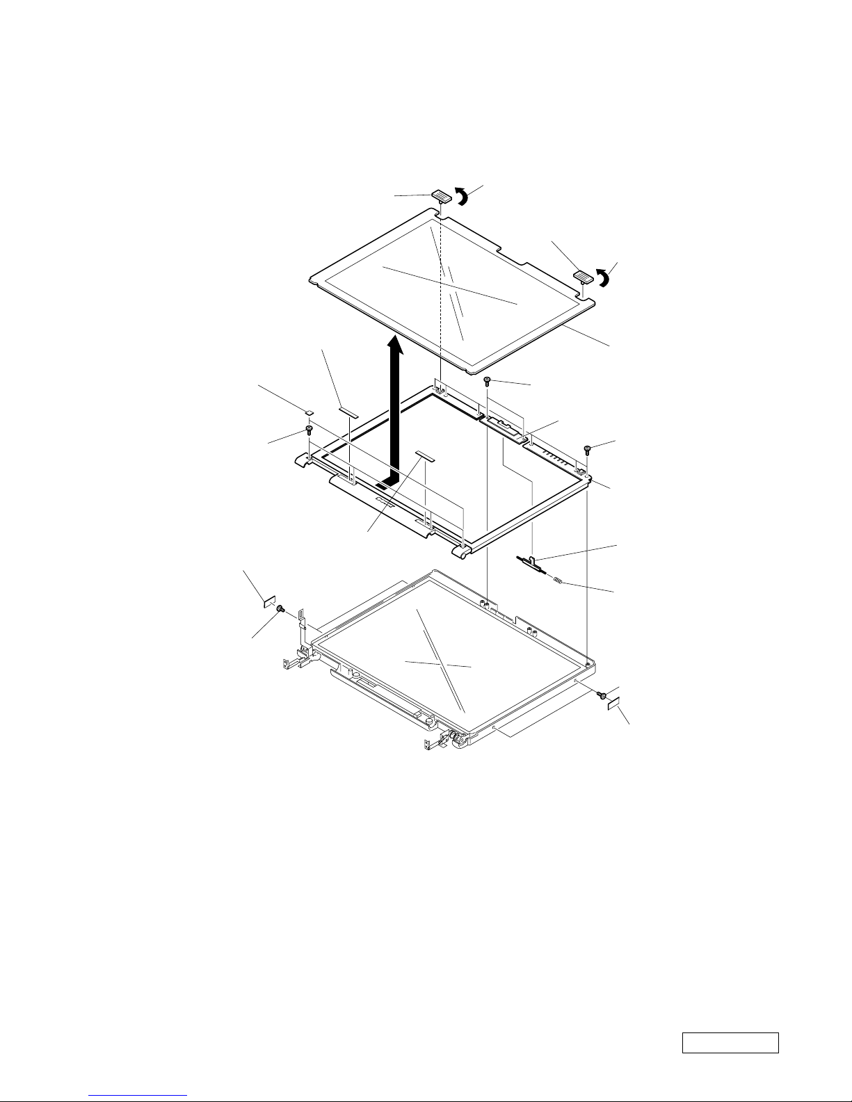
110. Flash Panel, Bezel Housing Assy
3
8 Special Head
Screw (M2) (x6)
0 Special Head Screw (M2) (x2)
5 Special Head
Screw (M2) (x2)
2 Panel Lock
2 Panel Lock
Flash Panel
4 LCD Side Seal (x2)
4 LCD Side Seal (x2)
5 Special Head
Screw (M2) (x2)
7 LCD Front
Screw (L) Seal
7 ID Label
8 Tapping P3
Screw (B2) (x4)
6 LCD Front
Screw Seal (x2)
9 Bezel Housing Assy
1
1
qs Latch (LCD)
qd Spring Latch
qa Latch Cover
1-8PCG-XE7 (I)
Confidential
(END)
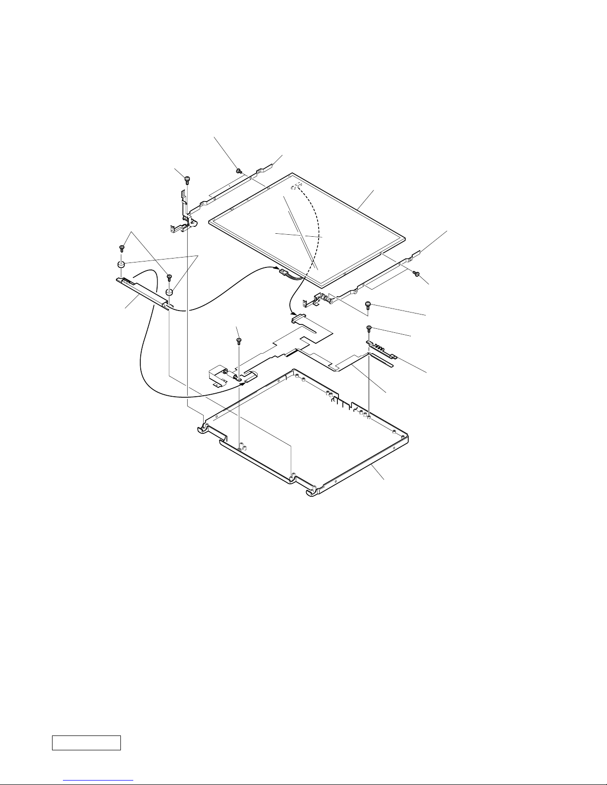
11. LCD Unit, Inverter Assy, LCD Flexible Print
6 Specail Head Screw (M2) (X2)
qf Specail Head
Screw (M2)
qg LED Lenz (A)
4 Specail Head
Screw (M2) (X2)
2 +PS2.6X8
2 +PS2.6X8
7 Hinge Assy 14 (L)
5 Hinge Assy 14 (R)
qh LCD Flexible Print
1
qd Specail Head
Screw (M2)
Hou Display 14 Assy
qs Inverter Assy
qa Inverter
Bracket
(x2)
3 LCD Unit
8
0 Special Head
Screw (M2) (X2)
9
 Loading...