

Sony Vaio PCG-R505DL, Vaio PCG-R505DSP, Vaio PCG-R505DS, Vaio PCG-R505DSK Service Manual
Confidential
SERVICE MANUAL
Notebook Computer
PCG-R505DL/R505DS/R505DSK/R505DSP
S400
9-874-513-01
Ver. 1-2002C
Revision History
For American Area
US Model
Canadian Model
Lineup: PCG-R505DL
PCG-R505DS
PCG-R505DSK
PCG-R505DSP
• Design and specifications are subject to
change without notice.

– 2 – PCG-R505DL/R505DS/R505DSK/R505DSP (AM)
Confidential
Information in this document is subject to change without notice.
Sony and VAIO are trademarks of Sony. Microsoft, MS-DOS,
Windows, the Windo ws 95, W indows 98, Windo ws 2000, W indows
ME and Windo ws XP logo are trademarks of Microsoft Corporation.
All other trademarks are trademarks or registered trademarks of
their respective owners. Other trademarks and trade names may be
used in this document to refer to the entitles claiming the marks and
names or their produces. Sony Corporation disclaims any proprietary
interest in trademarks and trade names other than its own.
Service and Inspection Precautions
1. Obey precautionary markings and instructions
Labels and stamps on the cabinet, chassis, and components identify areas
requiring special precautions. Be sure to observe these precautions, as
well as all precautions listed in the operating manual and other associated
documents.
2. Use designated parts only
The set’s components possess important safety characteristics, such as
noncombustibility and the ability to tolerate large voltages. Be sure that
replacement parts possess the same safety characteristics as the originals.
Also remember that the 0 mark, which appears in circuit diagrams and
parts lists, denotes components that have particularly important safety
functions; be extra sure to use only the designated components.
3. Always follow the original design when
mounting parts and routing wires
The original layout includes various safety features, such as inclusion of
insulating materials (tubes and tape) and the mounting of parts above the
printer board. In addition, internal wiring has been routed and clamped so
as to keep it away from hot or high-voltage parts. When mounting parts or
routing wires, therefore, be sure to duplicate the original layout.
4. Inspect after completing service
After servicing, inspect to make sure that all screws, components, and wiring
have been returned to their original condition. Also check the area around
the repair location to ensure that repair work has caused no damage, and
confirm safety.
5. When replacing chip components...
Never reuse components. Also remember that the negati ve side of tantalum
capacitors is easily damaged by heat.
6. When handling flexible print boards...
•The temperature of the soldering-iron tip should be about 270C.
•Do not apply the tip more than three times to the same pattern.
•Handle patterns with care; never apply force.
Caution: Remember that hard disk drives are easily damaged by
vibration. Always handle with care.
Caution Markings for Lithium/Ion Battery - The following or similar
texts shall be provided on battery pack of equipment or in both the
operating and the service instructions.
CAUTION: Danger of explosion if battery is incorrectly replaced.
Replace only with the same or equivalent type recommended by
the manufacturer. Discard used batteries according to the
manufacturer’s instructions.
CAUTION: The battery pack used in this device ma y present a fir e
or chemical burn hazard if mistreated. Do not disassemble, heat
above 100°C (212°F) or incinerate.
Dispose of used battery promptly.
Keep away from children.
CAUTION: Changing the back up battery.
•Overcharging, short circuiting, reverse charging, multilation
or incineration of the cells must bi avoided to prevent one or
more of the following occurrences; release of toxic materials,
release of hydrogen and/or oxygen gas, rise in surface
temperature.
• If a cell has leaked or vented, it should be replaced
immediately while avoiding to touch it without any protection.

– 3 – PCG-R505DL/R505DS/R505DSK/R505DSP (AM)
Confidential
TABLE OF CONTENTS
Section Title Page
CHAPTER 1. REMOVAL ...............................................1-1
Please confirm disassembly method by “Repair Manual” which
has been informed you separately.
CHAPTER 2. SELF DIAGNOSTICS.......................... 2-1
Please confirm “Self Diagnostics” method which will be informed
you with distribution of “Self Diagnostics” software.
CHAPTER 3. BLOCK DIAGRAM............................... 3-1
(to 3-2)
CHAPTER 4. FRAME HARNESS DIAGRAM........ 4-1
(to 4-2)
CHAPTER 5. EXPLODED VIEWS AND
PARTS LIST
5-1. Main Section.................................................................... 5-2
5-2. LCD Section .................................................................... 5-5
5-3. Accessories ...................................................................... 5-9
(to 5-9)
•Abbreviations
UC : US model / Canadian model
History of the changes is shown as the “Revision
History” at the end of this data.

1-1
PCG-R505DL/R505DS/R505DSK/R505DSP (AM)
Confidential
CHAPTER 1.
REMOVAL
< ATTENTION >
Please confirm disassembly method by “Repair Manual”
which has been informed you separately.
(END)

2-1
PCG-R505DL/R505DS/R505DSK/R505DSP (AM)
Confidential
CHAPTER 2.
SELF DIAGNOSTICS
< ATTENTION >
Please confirm “Self Diagnostics” method which will be informed
you with distribution of “Self Diagnostics” software.
(END)
PCG-R505DL/R505DS/R505DSK/R505DSP (AM)
Confidential
FPC
SWX-151
CNX-151
CNX-153
Power SW
SWX-87
IFX-18 2 IFX-183
MDC
MDC
Baterry
BP2R/BP4R
CNX-1 52
IFX-180
VCH
FW82807
VCH
FW82807
FWH
E82802
FWH
E82802
GMCH-M
FW82830MG
GMCH-M
FW82830MG
ICH3-M
FW82801
ICH3-M
FW82801
VID
Selector
FM3565
VID
Selector
FM3565
Core
Voltage
Regulator
CLK GEN
IMI9870GTD
(CK-Titan)
CLK GEN
IMI9870GTD
(CK-Titan)
Primary IDE
i.LINK
TSB43LV22
i.LINK
0
Audio
CODEC
YMF753
Audio
CODEC
YMF753
Ext-MIC
Headphone
Amp
Amp
Ether
82562
Ether
82562
RJ-45
Cardbus
R5C476
Cardbus
R5C476II
PC Card
Socket
Super I/O
LPC47N227
Super I/O
LPC47N227
EC/KBC/SPIC
H8S/2149
EC/KBC/SPIC
H8S/2149
CN
SMBUS0
I/O Expander
/SMBUS MU X
OZ998
I/O Expander
/SMBUS MU X
OZ9 98
VGA
DSub-15
ITP
Connector
SMBUS0
Flash
BIOS RO M
8 Mbit
CN
FAN
HDD
50pin
FPC
MDC
Connector
USB
Port0
FFC
CN
USB
Port1
EEPROM
(Password)
(ROMINFO)
EEPROM
(Password)
(ROMINFO)
PC133
Memory
BUS
AGT L
+
HL
HL
SMBUS2
PCI
LPC
SMBUS1
Battery
Connector
LCD
I/F
30pin
RJ-11
MS
Slot
MS
Chip
Debug
Port
Port0
Port1
Port2
Port3
Port4
USB Host
Controller0
CN
1
2
3
4
7
8
9
10
Docking Connector 100Pin
i.LINK
1
VGA
Ether
Pallarel
Serial
FDD
CN
FPC LED PWR/BATT/MS/W-LAN
DC Jack
Power
Supply
3.3V&5V
1.2V&1.8V
1.5V
Batt Charge
N.C
Port5
On Board Memory
Row#0
256Mbit x 4
PC133 SO-DIMM
144P Socket
Row#2, 3
PC133 SO-DIMM
144P Socket
Row#2, 3
ATF Sense
FAN Control
ADM1 030
ATF Sense
FAN Control
ADM1 030
SMBUS1
CPU
Pentum -m
&
Celeron
Processor
CPU
Pentum III-m
&
Celeron
Processor
uFCPGA
Connector
FFC
CN
FFC
CN
W-LAN
Module
802.1 1b
W-LAN
Module
802.1 1b
Mini PCI
124pin
Diversity Antenna
Speaker
Amp
Serial
Buffer
MAX3243
Serial
Buffer
MAX3243
PallarelSerial FDD
Int. KBD
Int. KBD
Touch P AD
Touch P AD
SWX-87
CN
CN
LCD 12.1" XGA
&
Inverter Board
LEX-32
5
6
8 9
1
2
CN
3
4
5
6
7
USB
Port5
USB
Port6
10
JogDial
L/R Butt on
SWX-88
AC LINK
CN
CN
CN
CN
DVO
B
USB Host
Controller1
USB Host
Controller2
USB Port5
USB Port6
VGA
Ether
i.LINK
1
LED Caps/Num/ScrLk
LED Caps/Num/ScrLk
SMBUS1
SMBUS1
PCGA-DSM5
PCGA-DSD5
i.LINK
TSB43AB22
3-1 3-2
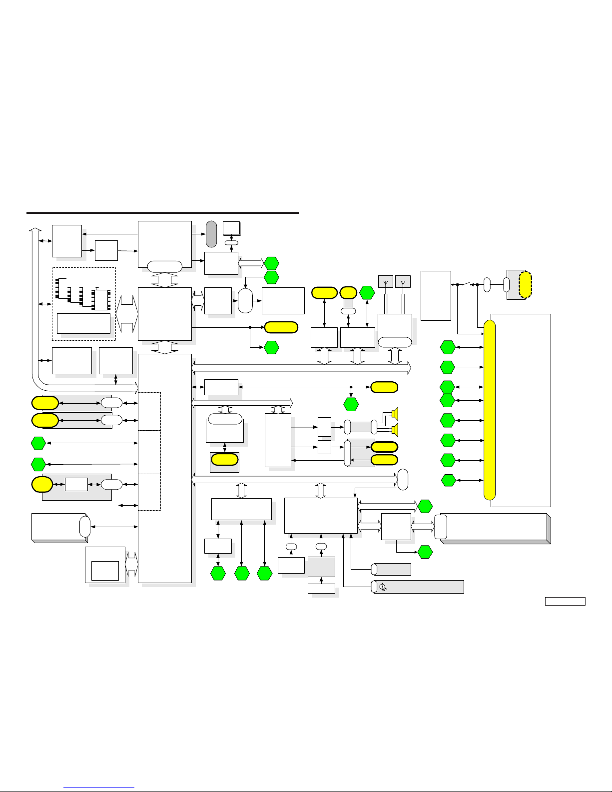
CHAPTER 3.
BLOCK DIAGRAM
(END)
PCG-R505DL/R505DS/R505DSK/R505DSP (AM)
Confidential
4-1 4-2
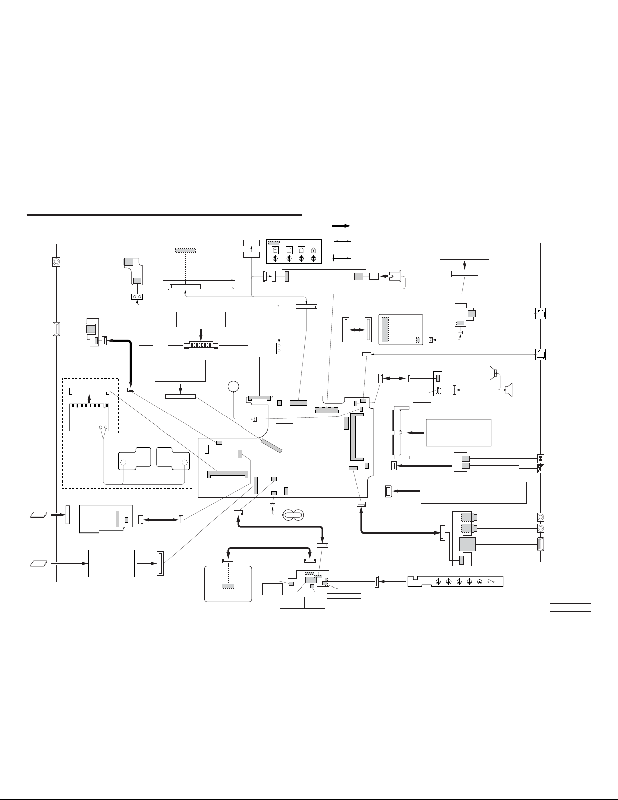
(END)
CHAPTER 4.
FRAME HARNESS DIAGRAM
18
1
A
1
2
18
81
CN3001
Rear
LITHIUM ION
BATTERY PACK
24 1
CN1901
KEY BOARD
CNX-153 BOARD
SIDE B
CN4302
USB
10
1
CN4301
110
CN1111
FLEXIBLE FLAT
CABLE (10 CORE)
WIRELESS
LAN CARD
IFX-182 BOARD
IFX-183
BOARD
IFX-180 BOARD
SIDE A
CN4602
12
1
12
1
CN1121
123 1
PC CARD
CONNECTOR
PC CARD
10
1
CN4601
MEMORY
STICK
2
1
79
80
CN1201
1
2
CN2801
CNX-154 BOARD
SIDE A
2
1
CN4402
CN4401
DC IN
130
CN701
LCD
LEX-32 BOARD
SIDE A
CN4901
INVERTER UNIT
HARNESS (LCD)
MODEM
CARD
J1
1
2
30
29
CN1602
CON2
CN5002
CN5001
MODULAR
JACK
CNX-152 BOARD
SIDE B
1
2
30
29
299
1 100
CN1401
DOCKING STATION
PCGA-DSD5/DSM5
CN1502
RJ-45 HARNESS (FOR INTERNAL)
NETWORK
2101
9
CN2002
10
1
CN4801
CN4802
1
4
SPEAKER
R ch
SWX-87 BOARD
SIDE B
S4801
FLEXIBLE
FLAT CABLE
(10 CORE)
POWER
SPEAKER
L ch
12
59 60
61 62
143 144
CN501
EXTENSION
MEMORY MODULE
PCGA-MM128E
CN1394
1
16
49150
2
CN2201
FPC (HDD)
HDD ASSY
PCG-R505DL: 30GB
PCG-R505DS, R505DSK, R505DSP: 40GB
CN4002
USB
J4004
MIC/LINE
INPUT
J4003
HEAD POHNE
CNX-151 BOARD
SIDE B
18
1
CN4001
i.LINK
DC OUT
118
CN1101
2
1
DC FAN
(WITH HEATSINK)
CPU
M
1
CN2001
20
2
CN4701
1
12
CN4702
S4702
S4701
S4704
S4703
ENCODER
(ROTARY)
SWX-88 BOARD
SIDE A
TOUCH PAD
CENTER
BUTTON
LEFT
BUTTON
RIGHT BUTTON
FLEXIBLE FLAT CABLE (20 CORE)
FLEXIBLE FLAT CABLE (12 CORE)
NICKEL HYDROGEN
BATTERY
CN2802
21
19
1
10
1
CN4703
19
FLEXIBLE PRINT (LED) PWB
Side L Side R
2
20
FLEXIBLE PRINT
(ILINK) PWB
HARNESS (POWER 2P)
FLEXIBLE
FLAT CABLE
(12 CORE)
FLEXIBLE FLAT CABLE
(NI SHIELD) 18P
HARNESS (2PIN)
From board to connector
(direct connection)
Harness
(with connectors on both ends)
Harness (soldering on either end)
MBX-62 BOARD
SIDE A
(EXCEPT: PCG-R505DL)
CN2101

5-1
PCG-R505DL/R505DS/R505DSK/R505DSP (AM)
Confidential
CHAPTER 5.
EXPLODED VIEWS AND PARTS LIST
NOTE:
• The mechanical parts with no reference number in the
exploded views are not supplied.
• Items marked “ * ” are not stocked since they are seldom
required for routine service. Some delay should be
anticipated when ordering these items.
• When the same reference numbers are written down in the
list, please use the one listed in the first place as the main
part.
The components identified by mark 0 or
dotted line with mark 0 are critical for safety.
Replace only with part number specified.
Les composants identifiés par une marque
0 sont critiques pour la sécurité. Ne les
remplacer que par une pièce portant le
numéro spécifié.

5-2
PCG-R505DL/R505DS/R505DSK/R505DSP (AM)
Confidential
58 4-662-893-01 SHEET, POWER HEAT SINK GROUND
59 4-663-129-01 PLATE (PALMREST), INTERCEPTION
60 4-662-968-01 REINFORCEMENT, KEYBOARD
61 4-660-015-01 COVER (REAR L)
62 X-4623-577-5 LID (DOG) ASSY
63 1-961-661-12 HARNESS, RJ-45
64 4-660-016-01 COVER (REAR R)
65 4-657-622-01 FOOT (R2)
66 1-683-865-11 PWB, FLEXIBLE PRINT
*67 4-660-022-01 BRACKET (HDD)
69 1-790-750-13 FPC (HDD)
70 A-8059-666-A (R505DS, R505DSK, R505DSP)...
ASSY HDD 40GB (T, 20, F) (S)
70 A-8059-226-A (R505DL)...
HDD (30GB, IC25N030ATCS04-0) (S)
71 4-641-449-01 FOOT (F)
72 X-4624-453-1 DOOR (VGA) ASSY
73 A-8059-716-A MBX-62 (A) (S)
74 4-649-669-11 CUSHION IFX
*75 4-660-052-01 HOLDER, ALMADOR
*76 4-660-053-01 FIN, ALMADOR
77 4-660-067-01 COVER (BOTTOM R)
78 4-660-524-01 SHEET (COIL), THERMAL
79 4-662-616-01 GASKET (FAN 1)
80 4-662-778-01 SHEET (HDD), SHIELD
81 4-662-843-01 SHEET (CS), SHIELD
82 4-662-881-02 CUSHION, KEYBOARD
83 4-662-354-01 COVER (HDD)
84 6-700-582-01 (R505DS, R505DSK, R505DSP)...
IC RH80530GZ006512
84 6-700-583-01 (R505DL)...IC RH80530GZ001512
B1 4-662-967-01 SCREW (2 TAPPING) (2X4)
B2 4-662-756-01 SCREW (1.4 TAPPING) (1.4X3.5)
B3 4-654-273-31 ACE (M2), LOCK (2X3.5)
B4 4-654-273-21 ACE (M2), LOCK (2X13)
B5 4-651-989-31 SPACER (MBX)
B6 4-635-966-01 SCREW (HEX)
B7 4-635-301-01 SCREW M3X4
B8 4-644-492-01 ACE (M2), LOCK (2X6)
B9 4-654-273-01 ACE (M2), LOCK (2X5)
B10 4-645-016-01 ACE (M2) (DIA. 4.6), LOCK (2X3)
Ref.No. Part No. Description
1 A-8067-097-A COMPLETE PWB SWX-88
2 1-823-811-11 CABLE, FLEXIBLE FLAT 20P
3 1-763-819-11 PWB, FLEXIBLE PRINT (FRONT LED)
4 1-476-762-31 ENCODER (ROTARY)
5 X-4624-454-2 (R505DS, R505DSK, R505DSP)...
HOUSING (PALMREST) (A) ASSY
5 X-4624-466-2 (R505DL)...HOUSING (PALMREST)
(B) ASSY
6 4-660-060-01 (R505DS, R505DSK, R505DSP)...
COVER (PALM), LENS
6 4-660-223-01 (R505DL)...COVER (PALM) (B), LENS
7 4-660-058-01 (R505DS, R505DSK, R505DSP)...
KNOB, SLIDE
7 4-660-603-01 (R505DL)...SPACER (LENS COVER)
8 4-654-382-01 CUSHION HDD CONNECTOR
9 1-796-319-11 PAD, TOUCH
10 4-660-059-02 ESCUTHEON (PAD)
11 1-823-813-11 CABLE, FLEXIBLE FLAT 12P
12 X-4624-451-1 COVER (SIDE L) ASSY
13 4-660-456-01 CUSHION (COVER SIDE)
14 X-4624-452-1 COVER (SIDE R) ASSY
15 1-825-082-11 SPEAKER, (2.0CM) BOX WITH
16 4-662-617-01 SHEET (FAN), INSULATING
17 1-823-812-11 CABLE, FLEXIBLE FLAT 10P
18 A-8067-107-A COMPLETE PWB SWX-87
19 X-4624-447-1 HOUSING (FRAME) ASSY
*20 4-660-019-01 KEYBOARD, PLATE
21 4-660-020-01 COVER, HINGE
22 1-960-827-51 HARNESS (2PIN)
23 A-8067-116-A COMPLETE PWB CNX-152
24 4-653-506-13 SHEET (MODEM)
25 1-477-114-21 KEYBOARD UNIT (US)
*26 1-763-809-11 FAN, DC (WITH HEATSINK)
27 4-660-523-01 SHEET (CPU), THERMAL
28 4-662-258-01 SHEET (MS), INSULATING
29 A-8067-098-A COMPLETE PWB IFX-180
30 1-823-814-11 CABLE, FLEXIBLE FLAT 12P
31 X-4624-494-1 ASSY BRACKET WIRE
32 1-761-380-23 CARD, MODEM
33 X-4624-743-1 ASSY COVER (BATTERY LOCK)
34 6-700-666-01 IC HYS64V16220GDL-7.5-C2
35 4-662-355-01 (R505DS, R505DSK, R505DSP)...
SHEET (WL), INSULATING
36 1-761-495-11 (R505DS, R505DSK, R505DSP)...
CARD, WIRELESS LAN
37 1-756-038-21 BATTERY, NICKEL HYDROGEN
*38 4-660-056-01 BRACKET (CPU)
*39 4-660-024-01 BRACKET (VGA)
40 4-654-239-01 INSULATING SHEET
41 4-660-018-02 INSULATOR (BOTTOM)
42 A-8067-114-A COMPLETE PWB CNX-154
43 1-779-745-31 JACK, DC
44 1-961-555-11 HARNESS (POWER 2P)
45 A-8067-101-A COMPLETE PWB CNX-153
46 1-793-100-11 CONNECTOR, USB
47 1-823-815-11 CABLE, FLEXIBLE FLAT 10P
*48 4-660-023-01 PLATE (PC CARD)
49 1-816-270-11 CONNECTOR, PC CARD
50 A-8067-119-A COMPLETE PWB CNX-151
51 1-816-281-11 JACK, SMALL TYPE (MICROPHONE)
52 1-695-514-21 JACK (SMALL TYPE) 1P (HEADPHONE)
53 1-823-816-11 CABLE, FLEXIBLE FLAT
54 4-654-610-03 COVER AIR DUCT
55 X-4624-450-1 HOUSING (BOTTOM) ASSY
56 4-662-966-01 SPACER (VGA)
57 4-663-912-01 ADHESIVE TAPE (5X80)
5-1. MAIN SECTION
Ref.No. Part No. Description
* When change the CPU (ref. 84), refer to “Replacing the CPU”
on page 5-7 and 5-8.

PCG-R505DL/R505DS/R505DSK/R505DSP (AM)
Confidential
5-3 5-4
46
44
43
45
B3
B3
B3
B3
B3
B3
B9
B3
B3
B3
B3
B6
B9
B5
B4
B5
B5
B10
B10
B5
B5
B10
B3
B3
B3
B3
B8
B8
B8
B7
B7
B3
B3
B3
B3
B9
B9
B1
58
82
B1
B9
B9
B3
B9
B9
B1
B2
B2
B2
B3
B3
B3
B3
47
46
52
51
50
54
53
72
14
13
3
59
2
1
4
5
6
7
8
9
10
12
13
11
49
8
48
71
69
70
83
67
66
55
65
64
63
65
62
41
40
61
57
42
38
80
74
74
56
79
37
26
84
28
29
30
31
76
81
32
33
34
39
73
6
7
15
78
75
16
17
18
19
20
21
25
21
60
22
23
24
1
2
3
4
6
7
8
5
wj
qa
qk
wf
ql
wg
wd
qj
qh
ef
ek
el
ek
el
ek
el
qk
9
0
qs
ej
ej
qd
qh
1
2
L
I
M
F
N
K
P
D
O
wj
qs
5
A
J
H
Q
wg
3
4
wd
qg
6
7
wa
es
ea
ws
e;
8
wh
qa
qf
qd
qg
wk
wa
ql
ea
w;
e;
ed
9
0
qj
P
Q
O
es ws
L
K
M
wk
ed
qf
wf
wl
N
I
F
wl
J
w;
eh
wh
A
E
E
G
G
H
D
B
C
77
ef
eg
eg
eh
36
27
35
B
C
PCG-R505DS, R505DSK,
R505DSP
PCG-R505DS,
R505DSK, R505DSP
PCG-R505DL
* When change the CPU (ref. 84), refer to “Replacing the CPU”
on page 5-7 and 5-8.
PCG-R505DL/R505DS/R505DSK/R505DSP (AM)
Confidential
5-5 5-6
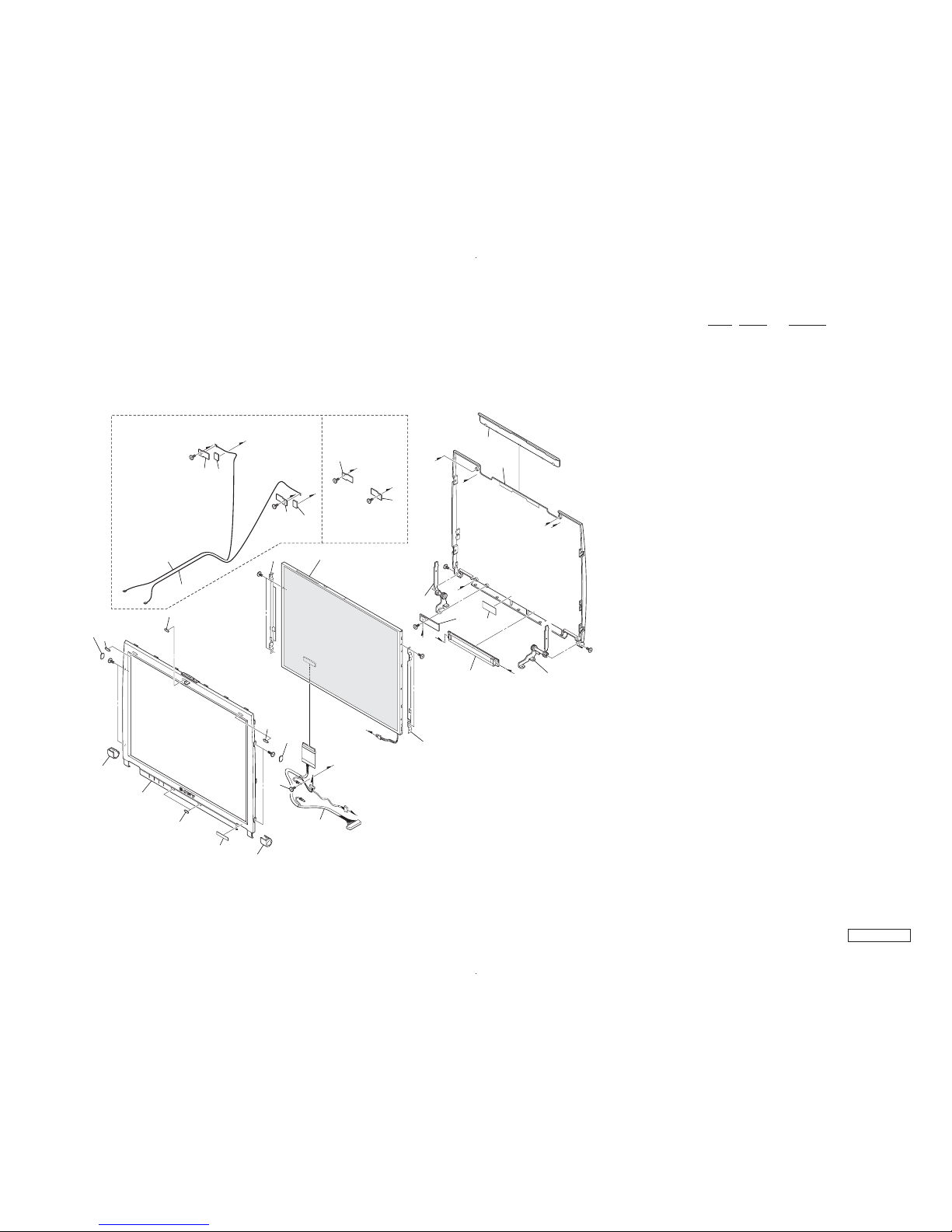
5-2. LCD Section
C
C
B
1
2
2
3
4
3
3
5
5
4
2
1
A
B
A
122
123
B11
B11
B10
B10
B10
B10
B11
B10
119
B10
126
120
B10
126
121
121
118
116
115
125
117
114
110
104
101
105
107
106
111
109
108
B10
B11
109
108
112
113
124
124
PCG-R505DS, R505DSK,R505DSP PCG-R505DL
Ref.No. Part No. Description
101 X-4624-448-1 HOUSING (BEZEL) ASSY
104 4-660-035-01 COVER (DL)
105 4-660-036-01 COVER (DR)
106 4-660-039-01 BLIND (LCD B), HOLE
107 4-663-268-01 (R505DSP)...LABEL (ID) (U)
107 4-663-268-11 (R505DSK)...LABEL (ID) (U)
107 4-663-268-21 (R505DS)...LABEL (ID) (U)
107 4-663-268-31 (R505DL)...LABEL (ID) (U)
108 4-652-933-02 BLIND (SIDE), HOLE
109 4-660-038-01 BLIND (LCD), HOLE
110 4-652-938-02 CUSHION (LATCH)
111 1-961-579-11 HARNESS (LCD)
* 112 4-660-031-01 BRACKET (LCD-L)
* 113 4-660-032-01 BRACKET (LCD-R)
114 A-8059-714-A LCD (12.1)(H)(S)
115 A-8067-109-A COMPLETE PWB LEX-32
116 1-476-317-12 INVERTER UNIT
* 117 4-660-033-01 TILT UNIT (L)
* 118 4-660-034-01 TILT UNIT (R)
119 A-8067-103-A (R505DS, R505DSK, R505DSP)...
COMPLETE PWB IFX-182
120 A-8067-105-A (R505DS, R505DSK, R505DSP)...
COMPLETE PWB IFX-183
121 1-823-844-11 (R505DS, R505DSK, R505DSP)...
CABLE, COAXIAL
122 X-4624-449-1 HOUSING (DISPLAY) ASSY
123 4-660-029-01 COVER (DISPLAY)
124 4-662-650-01 (R505DS, R505DSK, R505DSP)...
GASKET (W-LAN)
125 4-649-669-11 CUSHION IFX
126 4-663-174-01 (R505DL)...SPACER (W-LAN)
B10 4-645-016-01 ACE (M2) (DIA. 4.6), LOCK (2X3)
B11 4-643-356-01 SCREW (M2X5)
PCG-R505DL/R505DS/R505DSK/R505DSP (AM)
Confidential
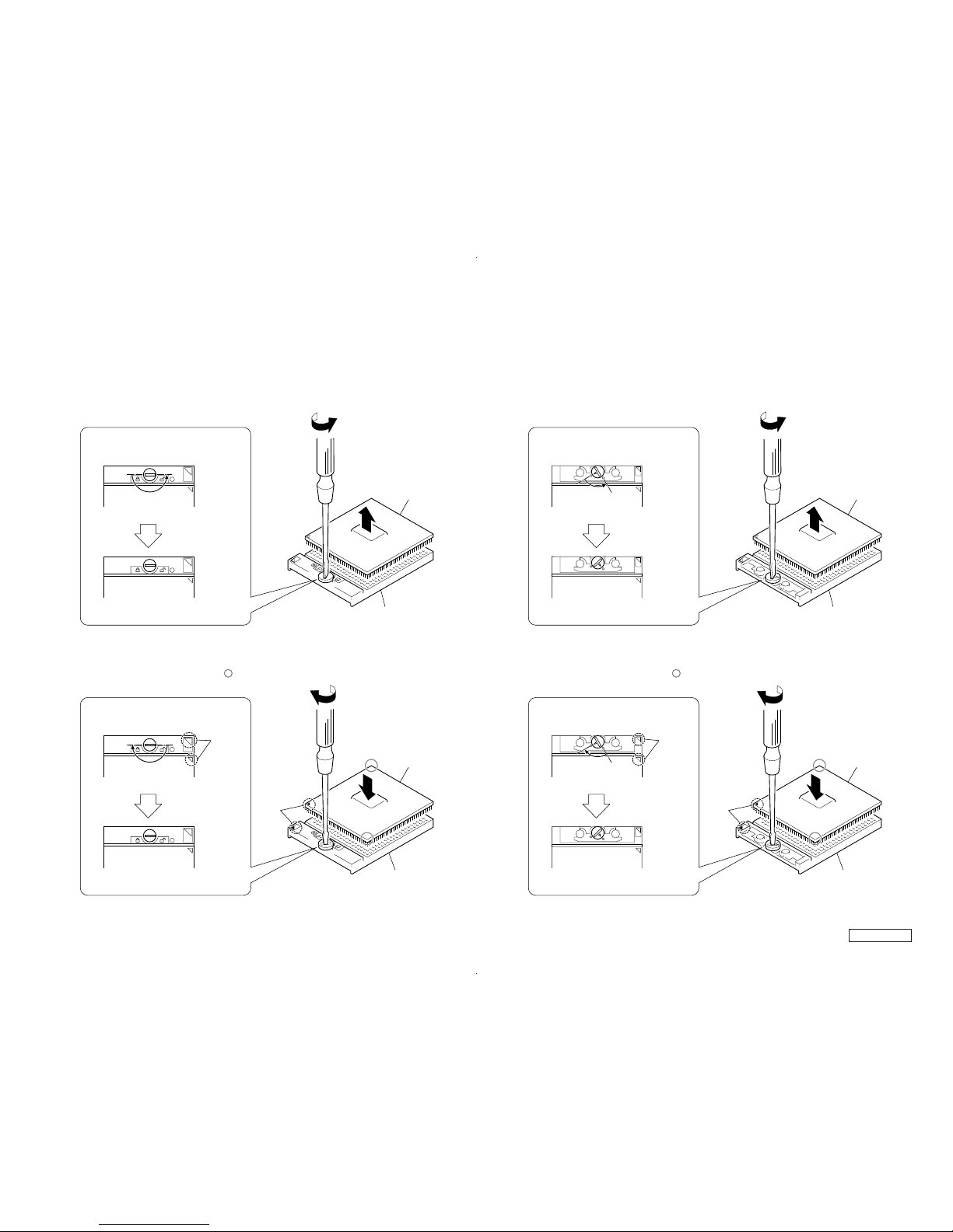
• Replacing the CPU
Note: We have two kinds of CPU for this set, and either of them is used.
Two kinds of CPU have differences in the lock position and the unlock position.
1. Socket configuration 1
2. Socket configuration 2
5-7 5-8
1. How to remove the CPU
2. How to install the CPU
(FOX)
lock position
unlock position
unlock position
lock position
1 Rotate the lock with a flat-blade screwdriver toward
the unlock position shown in the figure.
2 Remove up the CPU.
2
CPU
1 Position the mark on the CPU to the mark on the CPU
socket and put in all pins to the holes on the CPU socket.
2 Pressing two corners marked with in the figure,
rotate the lock with a flat-blade screwdriver toward
the lock position.
(FOX)
mark
mark
Note: Lock the CPU properly, or operation
becomes unstable.
CPU socket
CPU socket
1
CPU
2
2
(AMP)
1
2
2
CPU
(AMP)
1
CPU
1. How to remove the CPU
lock position
unlock position
unlock position
lock position
1 Rotate the lock with a flat-blade screwdriver toward
the unlock position shown in the figure.
2 Remove up the CPU.
mark
CPU socket
CPU socket
2. How to install the CPU
1 Position the mark on the CPU to the mark on the CPU
socket and put in all pins to the holes on the CPU socket.
2 Pressing two corners marked with in the figure,
rotate the lock with a flat-blade screwdriver toward
the lock position.
mark
Note: Lock the CPU properly, or operation
becomes unstable.
5-9
PCG-R505DL/R505DS/R505DSK/R505DSP (AM)
Confidential
(END)
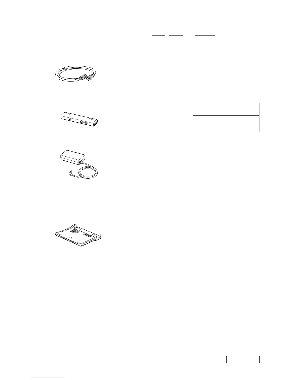
5-3. Accessories
Ref.No. Part No. Description
ACCESSORIES
***********
0 201 1-575-562-21 CORD, POWER
202 1-756-152-41 BATTERY PACK, LITHIUM ION
0 203 1-477-205-11 ADAPTOR, AC
4-646-847-11 (R505DSK)...W2K FIRST STEP GUIDE
4-661-919-01 QUICK START
LOOK AT EXPLODED VIEWS OF THE PART
**********************************
204 PCGA-DSM5
201
Power Cord
202
Battery Pack
203
AC Adaptor
204
Docking Station
(PCGA-DSM5)
* The main unit is not assigned with a part number.
Refer to the PCGA-DSD5/DSM5 Service Manual
(9-874-401-11).
The components identified by mark 0 or
dotted line with mark 0 are critical for safety.
Replace only with part number specified.
Les composants identifiés par une marque
0 sont critiques pour la sécurité. Ne les
remplacer que par une pièce portant le
numéro spécifié.

®
VAIO
Notebook
Quick Start
PCG-R505 Series


Contents
Welcome.......................................................5
Features.......................................................................5
Unpacking Your Notebook .. .......................................6
Registering Your Notebook ........................................8
Setting Up Your Dial-Up Connection.........................9
Setti ng Up Your VAIO Notebook..............13
Locating Controls and Ports......................................14
Connecting the Docki ng St ation ............. ............ ......20
Disconn ect i n g the Docking Stat i o n.. ....... ............ ......22
Connecting a Power Source ........... ....... ........... ....... ..26
Starting Your Notebook .... ....... ............ ....... ....... .......32
Shutting Down Your Notebook.................................33
Using Power Saving Modes......................................34
Adding Memory.........................................37
Precau tio n s an d Pro ced u res............ ....... ....... ........... ..38
Removing a Memory Module ............................. ......40
Installing a Memory Module.....................................41
Viewing the Amount of Memory..............................44
3

V AIO® Notebook Quick Star t
About the Software on Your Not eb ook...45
Overview of the Sof tware on Your Notebook..........46
Application, Driver, and System Recovery CDs......54
Using You r Recov e r y CDs.... ............ ....... ........... .....55
Troubleshooting........................................61
Troubleshooting Your Notebook........................... ...62
Troubleshooting the Docking Station.......................65
Troubleshooting the LCD Screen .......................... ...66
Troubleshooting the Mous e and Touchpad ........... ...66
Getting Help...............................................69
Suppor t Op ti o n s....... ........... ............ ....... ............ .......70
Software Support Information..................................72
Sony Serv i ce Center........ ....... ............ ....... ........... .....74
Index........................................................... 75
4

Welcome
Congratulati ons o n your p ur chas e of t he Sony VAIO® notebook. Sony h as
combined leading-edge technology in audio, vi deo, computing, and
communications to provide you with state-of-the-art personal c omputing.
Features
✍ For complete specifications of your VAIO® notebook, refer to the Spe cifica tions
flyer supplied with your not ebook.
❑ E xceptional performa nce — Your notebook includes a mobile Intel®
Pentium® III processor
*
and a V.90 modem.
†
❑ Portabilit y — Rechargeable battery pack provides hours of use without
AC power, even while you use th e optional docking station.
❑ Sony audio and video quality — High-quality MPEG2 video, which
supports full-screen display (12.1-inch Active Matrix LCD screen) and
enable s you to take advantage of today’s ad vanced multimedia applications,
games, and entert ainment software.
❑ Multimedia feat ures — Enjoy the stereo speak ers or us e hea dphones (not
supplie d) to listen to audi o and video CDs.
❑ Microsoft® Windows® oper atin g system — Your system includes the
latest Mic r os oft® Windows® operating system.
❑ Communications — Access popular online services, send e-mail, browse
the Internet, and us e fax features.
* CPU speed will be reduced und er certain operating cond itions.
† Actual upload and do w nload speeds may vary du e to line conditions, IS P s upport, a nd gov-
ernme nt regu la ti ons .
5
V AIO® Notebook Quick Star t
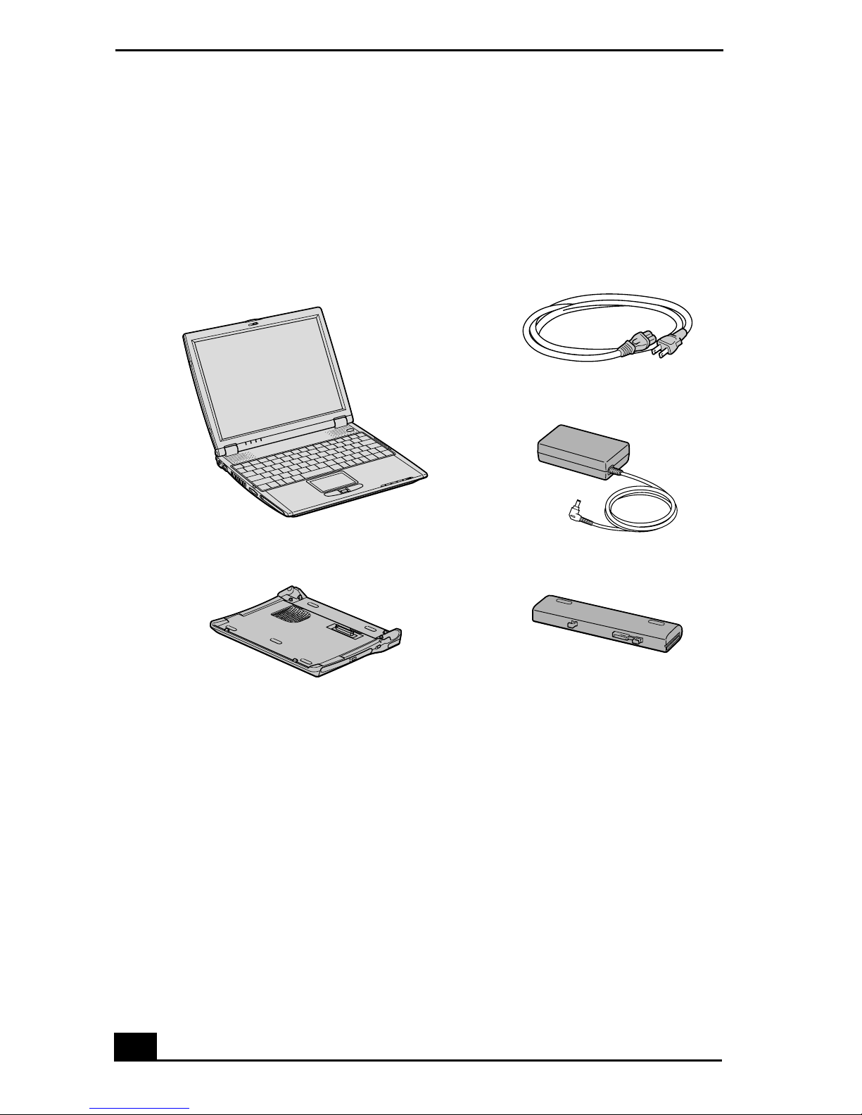
Unpacking Your Notebook
Remove the following hardware, documents, and CDs from the box:
Hardware
Main Unit Power Cord
AC Adapter
Docking Station
* Docking station supplied with selected models.
*
Rechargeable Battery Pack
Documents
❑ VAIO® R505 SuperSlim Pro™ Notebook Quick Start — Contains details
on unpacking and setting up your n otebook, supple me ntary updates, and
software information.
❑ Microsoft® Windows® manual — Explains how to use the basic features
of the late st Windows ope rating syst em .
❑ VAIO® Note book Specifications flyer — Details th e hardware
specifications for your notebook and the docking station, which is supplie d
with se lected models .
6

Unpacking Your Notebook
❑ VAIO® Notebook Notes on Use — Explains notes on use and offe rs safety
tips.
Software CDs
❑ Microsoft® Word — Enables you to reinstall Microsof t Word to the
VAIO® computer you purchased, if the application becomes corrupted or is
erased.
Recovery CDs
❑ Application Recovery CD(s) — Enables you to reinstall indi vidual
applications if they become corrupted or are erased.
❑ Driver Recovery CD(s) — Enables you to reinstall individual device
drivers if they become corrupted or are erased.
❑ System Recovery CD(s) — Enables you to re store the oper ating sys t em and
software tha t sh ipped with your computer if they become corrupted or are
erased. This CD restores your computer to its original factory set tings, so
user data and applicati ons installed s ince you started using your compute r
will be los t.
✍ To us e these recovery CDs, connect th e docking st ation (su pplied wit h selecte d
models) or an optional opt ical dri v e, such as a fully atapi com pliant PC C ard CDROM drive , to the notebook.
Other
❑ Packet containing spec ial product of fers
❑ Limited Warranty Card
7

V AIO® Notebook Quick Star t
Registering Your Notebook
Take advantage of Sony’s commitment to quality customer support and receive
these bene fits by registering your notebook:
❑ Sony Customer Support — Talk to a Support Representative to
troubles hoot problems you may be having with your notebook.
❑ Limited War ranty — Protect your investme nt. See the Limited Warranty
Card for more details.
✍ You are prompted to regis ter your computer t he first time you turn on the unit .
Follow the on-scr een instruct ions to complete the registra tion pr ocess. If yo u are not
able to register your computer during the first session, you are provided with
additional registration oppor tuniti es later.
8
Setting Up Your Dial-Up Connection
Settin g U p Your Di al-Up Connect io n
This section describes the basic steps for setting up your dial-up conne ction. The
Connecti on Wiza rd guides you through the process of connecting to the Internet
and choosing an Internet Service Provider (ISP) or setting up an existing account.
Setting up your Internet connection (Microsoft® Windows®
XP oper ati n g system)
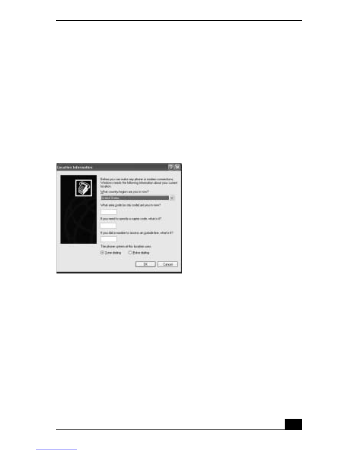
1 Click Start, point to All Programs, Acces sories, Co mmunications , and then
click New Connec tion Wiz ard. The Location Information window appears.
Location Information window
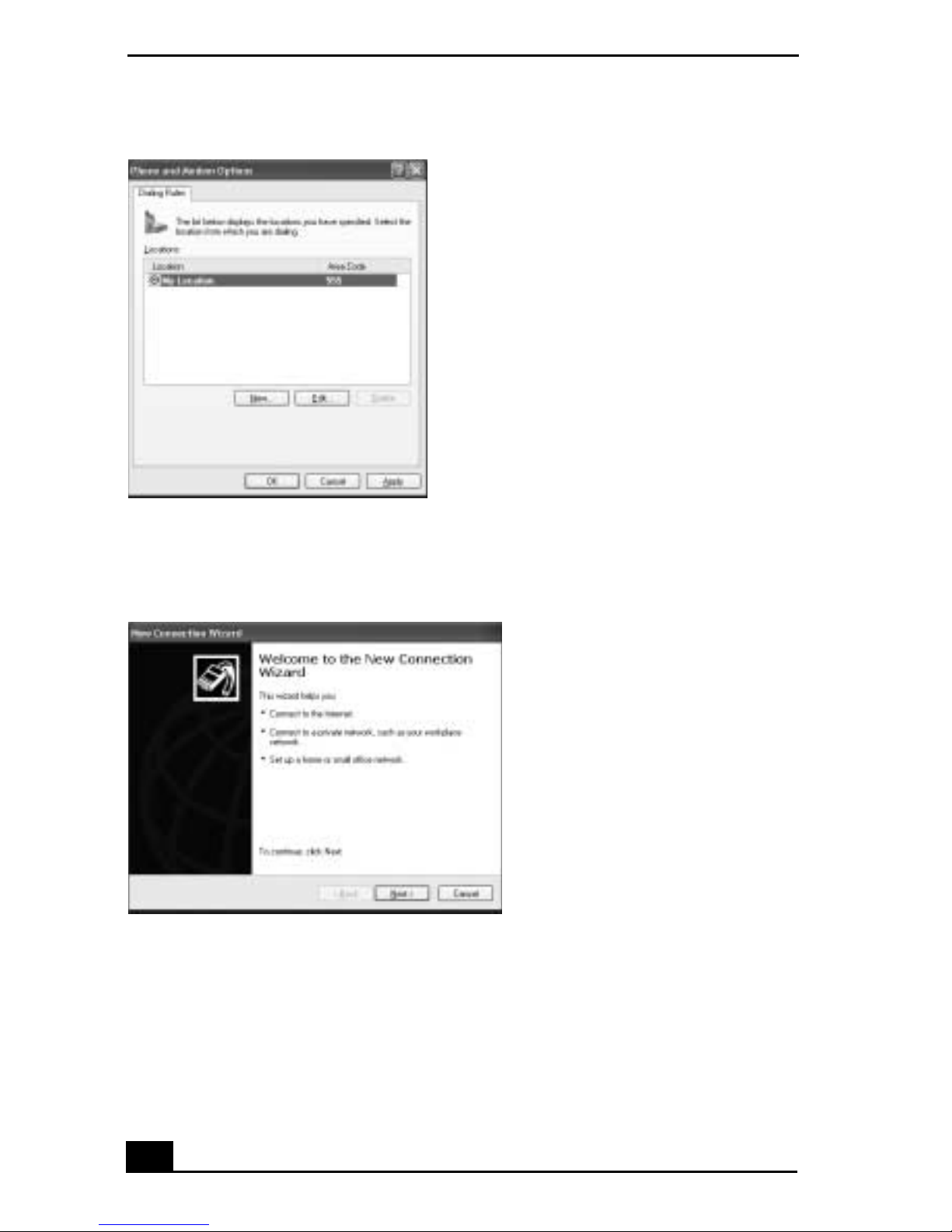
2 Follow th e on-scree n instr uctions , and t hen clic k OK to contin ue. The Phone
and Modem Options window appears.
9
V AIO® Notebook Quick Star t
Phone and Modem Options window
3 Select th e loc ation from where you are dial ing and then click OK. The New
Connecti on Wizard window appears.
New Connection Wizar d window
4 Follow the on-screen instructions to finish setting up your Internet
connection.
10
Setting Up Your Dial-Up Connection
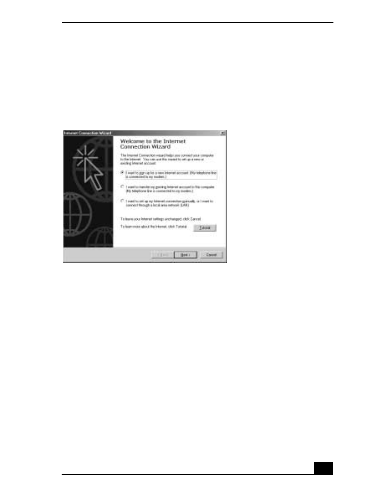
Setting up your dial-up connection (Microsoft® Windows®
2000)
1 Click St ar t, p oint to P rogr ams, Access ori es, Com municati ons, and t hen cli ck
Internet Connection Wizard. The Internet Connecti on Wizar d window
appears.
Internet Connection Wizard window.
2 Follow the on-screen instructions to finish setting up your Internet
connection.
11

V AIO® Notebook Quick Star t
12

Setting Up Your VAIO Notebook
This section describes the following:
❑ Locating Controls an d Ports
❑ Connecting the Docking S tation
❑ Disconnecting the Docking Station
❑ Connecting a Power Source
❑ Starting Your Notebook
❑ Shutting Down Your Notebook
❑ Using Power Saving Modes
13
V AIO® Notebook Quick Star t
Locating Controls and Ports
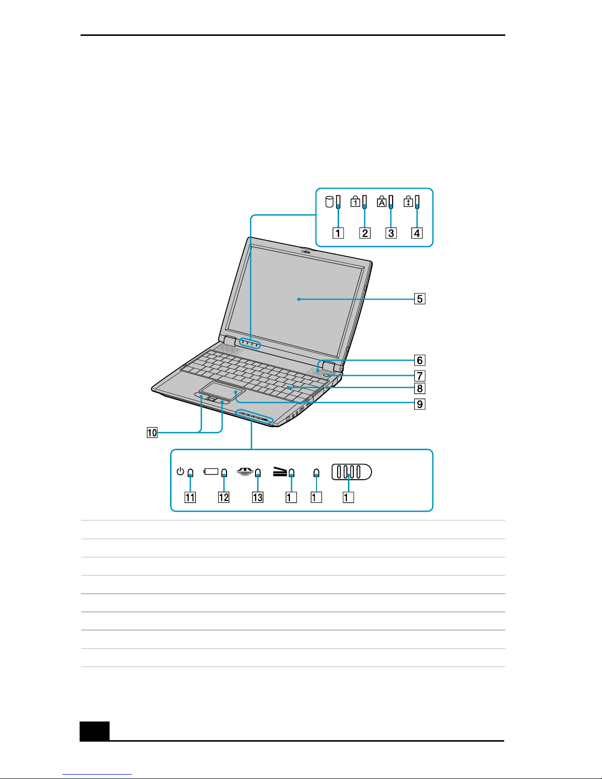
On the Notebook
Front
OFF ON
WIRELESS
LAN
5
4
6
1 Hard disk drive indicator 9 Touchpad
2 Num lock indi cator 10 Left and right buttons
3 Caps lock indicator 11 Power indicator
4 Scro l l lo ck indica to r 12 Battery indicator
5 LCD screen 13 Memory St ick® indic ator
6 Speakers 14 Docking station indicator
7 Power button 15 Wireless LAN indi cator
8 Keyboard 16 Wireless LAN switc h
* Wirel es s LAN cap abi lities are available on sele cte d mod e ls.
*
*
14
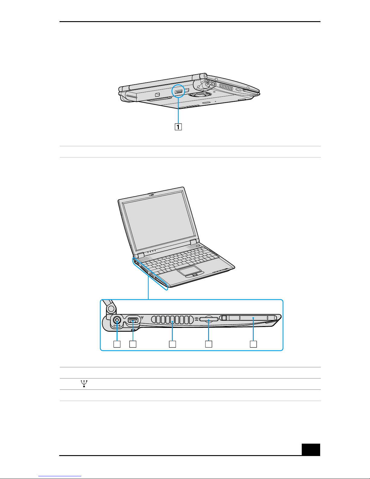
Back
1 Battery port
Left
Locating Controls and Ports
1
1 DC In port 4 Memory Stick® slot
2 USB port 5 PC Card slot
3 Air vent
2 3 4
5
15
V AIO® Notebook Quick Star t
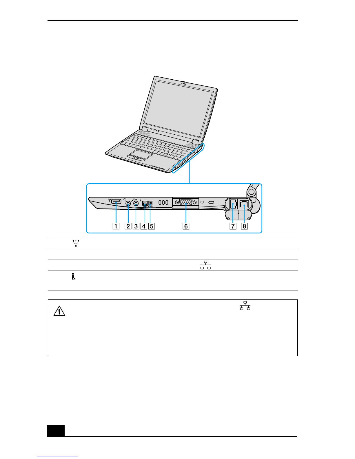
Right
1 USB port 5 Peripheral device DC Out port
2 Headphone jack 6 Monitor port
3 Microphone jack 7 Ethernet port
4 i.LINK® (IEEE 1394) S400
8 Phone line ja ck
port
Only connec t 1 0BASE-T and 10 0BASE-TX cabl es to the Ethe rnet por t.
Do not con n ect any other type of network cable or an y telephone line.
Connec ting cable s other than those listed above may result in an electric
current overload and coul d cause a malfunction, excessive heat, or fire in
the port. To connect the unit to the networ k, contact your network
administrator.
16
 Loading...