

Sony VAIO PCG-FXA47, VAIO PCG-FXA49 Service Manual
Confidential
PCG-FXA47/FXA49
SERVICE MANUAL
NOTEBOOK COMPUTER
9-874-507-01
For American Area
US Model
CanadianModel
Lineup : PCG-FXA47
PCG-FXA49
• Design and specifications are subject to
change without notice.
S400
Illust : PCG-FXA49
Ver 1-2002A
Revision History
— 2 —
Information in this document is subject to change without notice.
Sony and VAIO are trademarks of Sony. Intel logo and Intel Inside
logo are registered trademarks of Intel Corporation. Pentium MMX
is a trademark of Intel Corporation. Microsoft, MS-DOS, Windo ws,
the Windo ws 95 and W indows 98 logo are trademarks of Micr osoft
Corporation.
All other trademarks are trademarks or registered trademarks of
their respective owners. Other trademar ks and trade names may be
used in this document to refer to the entitles claiming the marks and
names or their produces. Sony Corporation disclaims any proprietary
interest in trademarks and trade names other than its own.
Service and Inspection Precautions
1. Obey precautionary markings and instructions
Labels and stamps on the cabinet, chassis, and components identify areas
requiring special precautions. Be sure to observe these precautions, as well
as all precautions listed in the operating manual and other associated
documents.
2. Use designated parts only
The set’s components possess important safety characteristics, such as
noncombustibility and the ability to tolerate large voltages. Be sure that
replacement parts possess the same safety characteristics as the originals.
Also remember that the 0 mark, which appears in circuit diagrams and
parts lists, denotes components that have particularly important safety
functions; be extra sure to use only the designated components.
3. Always follow the original design when mounting
parts and routing wires
The original layout includes various safety features, such as inclusion of
insulating materials (tubes and tape) and the mounting of parts above the
printer board. In addition, internal wiring has been routed and clamped so
as to keep it away from hot or high-voltage parts. When mounting parts or
routing wires, therefore, be sure to duplicate the original layout.
4. Inspect after completing service
After servicing, inspect to make sure that all screws, components, and wiring
have been returned to their original condition. Also check the area around
the repair location to ensure that repair work has caused no damage, and
confirm safety.
5. When replacing chip components...
Never reuse components. Also remember tha t the negativ e side of tantalum
capacitors is easily damaged by heat.
6. When handling flexible print boards...
• The temperature of the soldering-iron tip should be about 270C.
• Do not apply the tip more than three times to the same pattern.
• Handle patterns with care; never apply force.
Caution: Remember that hard disk drives are easily damaged by
vibration. Always handle with care.
Caution Markings for Lithium/Ion Battery - The following or similar
texts shall be provided on battery pack of equipment or in both the
operating and the service instructions.
CAUTION: Danger of explosion if battery is incorrectly replaced.
Replace only with the same or equivalent type recommended by
the manufacturer. Discard used batteries according to the
manufacturer’s instructions.
CAUTION: The battery pac k used in this device may present a f ire
or chemical burn hazard if mistreated. Do not disassemble, heat
above 100°C (212°F) or incinerate.
Dispose of used battery promptly.
Keep away from children.
CAUTION: Changing the back up battery.
• Overcharging, short circuiting, reverse charging, multilation or
incineration of the cells must be avoided to prevent one or mor e of
the following occurrences; release of toxic materials, release of
hydrogen and/or oxygen gas, rise in surface temperature.
• If a cell has leaked or vented, it should be replaced immediately
while avoiding to touch it without any protection.
PCG-FXA47/FXA49 (AM)
Confidential
ATTENTION AU COMPOSANT AYANT RAPPORT
À LA SÉCURITÉ!
LES COMPOSANTS IDENTIFÉS P AR UNE MARQUE 0 SUR LES
DIAGRAMMES SCHÉMA TIQUES ET LA LISTE DES PIÈCES SONT
CRITIQUES POUR LA SÉCURITÉ DE FONCTIONNEMENT. NE
REMPLACER CES COMPOSANTS QUE PAR DES PIÈSES SONY
DONT LES NUMÉROS SONT DONNÉS DANS CE MANUEL OU
DANS LES SUPPÉMENTS PUBLIÉS PAR SONY.

— 3 —
TABLE OF CONTENTS
Section Title Page
PCG-FXA47/FXA49 (AM)
Confidential
CHAPTER 1. REMOVAL ............................................... 1-1
(to 1-1)
CHAPTER 2. SELF DIAGNOSTICS....................... 2-1
(to 2-1)
CHAPTER 3. BLOCK DIAGRAM............................... 3-1
(to 3-2)
CHAPTER 4. FRAME HARNESS DIAGRAM........ 4-1
(to 4-2)
CHAPTER 5. EXPLODED VIEWS AND
PARTS LIST............................................5-1
5-1. Main Section.................................................................... 5-2
5-2. FDD Section .................................................................... 5-5
5-3. LCD Section (FXA49 Model) – Made by NE –..............5-7
5-4. LCD Section (FXA47 Model) – Made by AC –.............. 5-9
5-5. Connector Section (CH Type only)................................ 5-11
(to 5-12)
History of the changes is shown as the
“Revision History” at the end of this data.

1-1
Confidential
PCG-FXA47/FXA49 (AM)
CHAPTER 1.
REMOVAL
(END)
ATTENTION
Please confirm disassembly method by “Repair Manual” which has been informed you
separately.
2-1
Confidential
PCG-FXA47/FXA49 (AM)
CHAPTER 2.
SELF DIAGNOSTICS
Please confirm “Self Diagnostics” method which will be informed you with distribution
of “Self Diagnostics” software.
ATTENTION
(END)
Confidential
PCG-FXA47/FXA49 (AM)
(END)
3-23-1
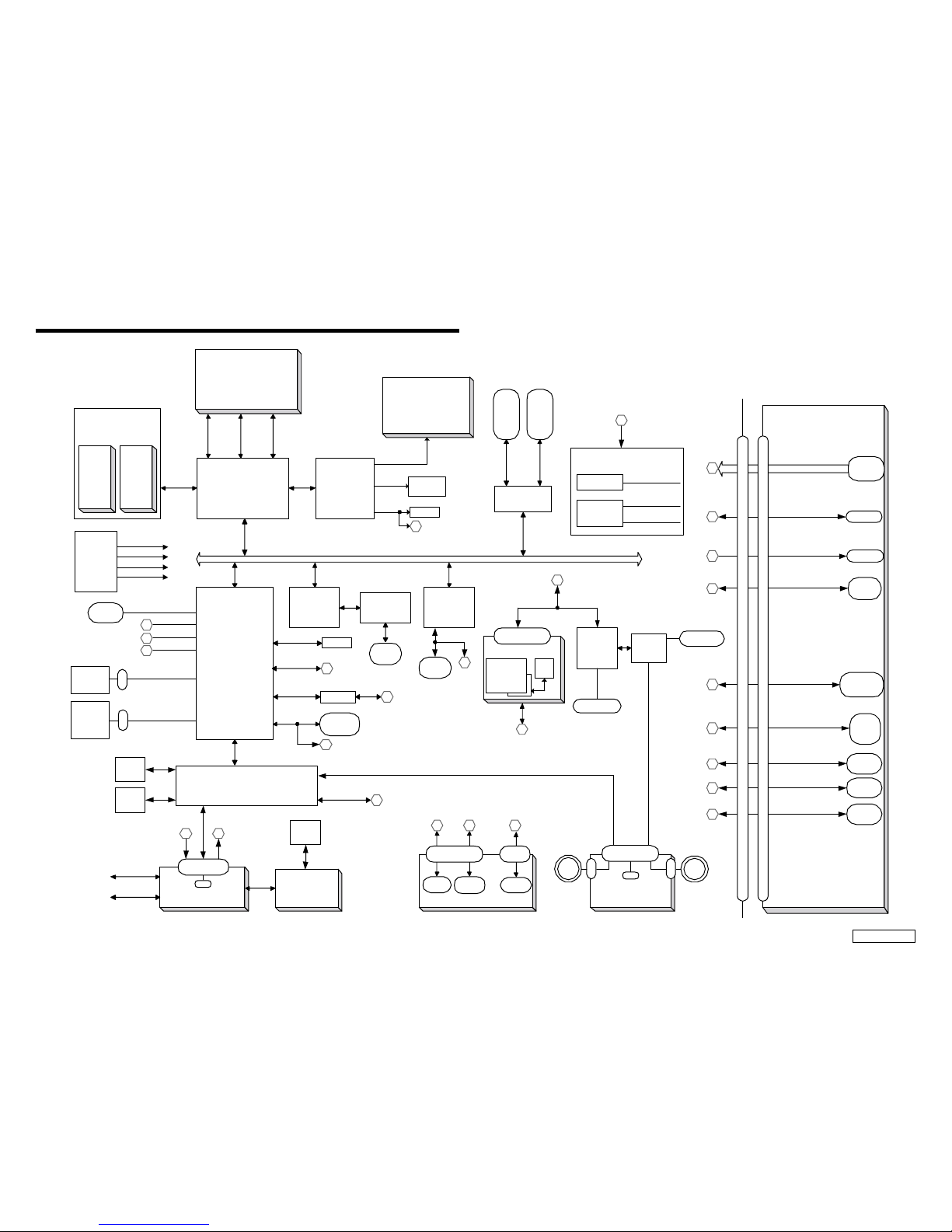
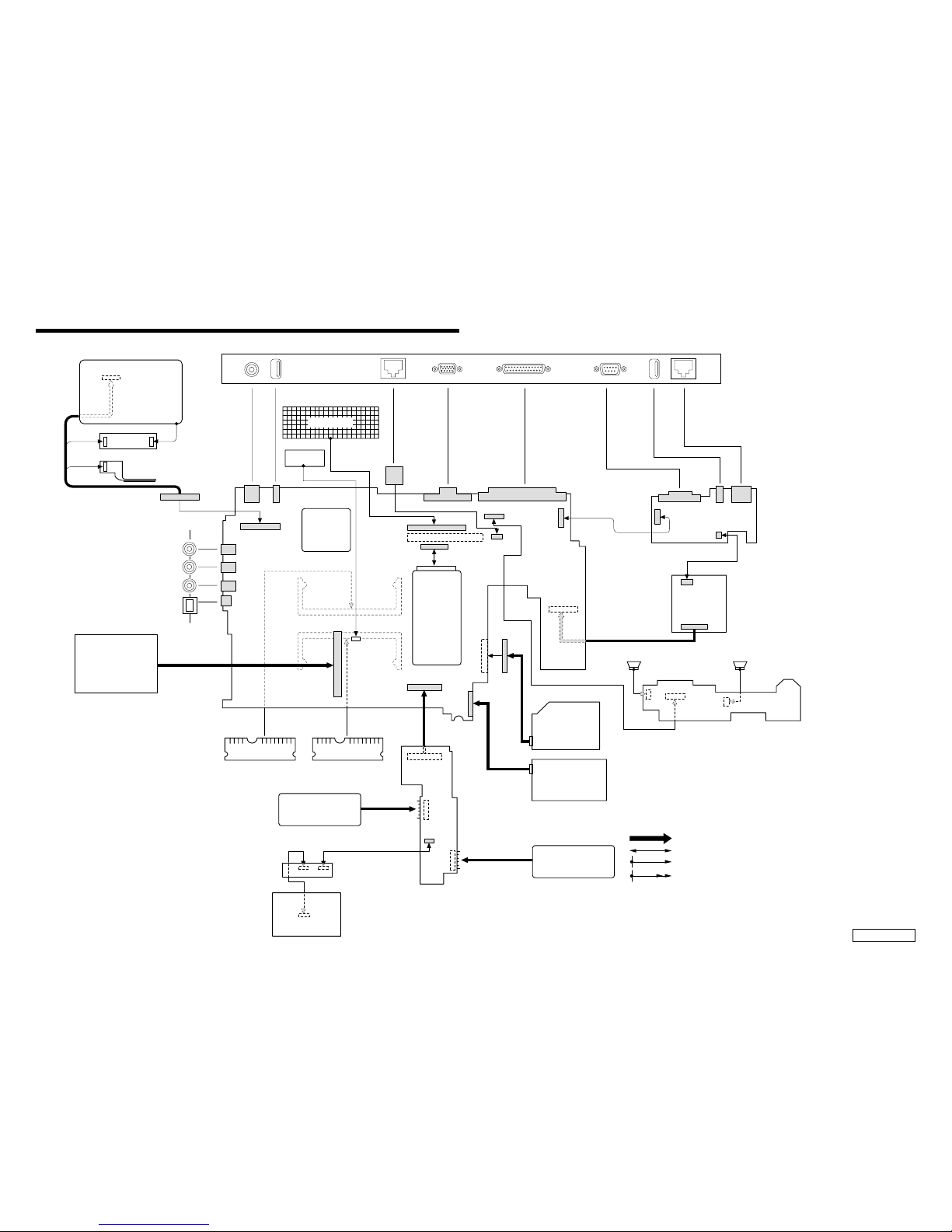
CHAPTER 3.
BLOCK DIAGRAM
Port Replicator
PCI BUS
CLK GEN
ICS9248BF-168
CPU CLOCK
PCI CLOCK
USB CLOCK
Serial
DSUB-9
Parallel
DSUB-25
PS/2
MDIN-6
USB 1
VGA
6
4
5
7
3
Main System Board MBX-61
CNX-126
DC-IN
1
14M CLOCK
11
LCD Panel
14.1"/15" TFT
XGA
CARD BUS
TI PCI1420
PC Card
Socket 1
PC Card
Socket 2
PCU
NS KBC
PC 87570
ISA
BATTERY 0
T/P BOARD
CNX-129
DC/DC BOARD
PWS-14
I/O SUB BOARD CNX-150
USB 1
Serial
D SUB-9
RJ-11
CN
2-pin
POWER CIRCUIT
MAXIM 1711
MAXIM 1632A
CPU-VCC
CORE
3V/3 VSUS
5V/5 VSUS
12
47
PCG-FX Series
BLOCK DIAGRAM Rev.A
w/ Port Replicator (PCGA-PRFX1) 2001/08/27
CN
18-pin
Main Memory
PC100 SO-DIMM
256MB X1/256MB X2
(Max.512MB)
SO-DIMM
Slot B
North Bridge
VIA KT133A
VT8363A
D RAM
SIG NAL
ADDRESS
DATA
CTRL
SIGNAL
CPU
AMD Mobile Athlon 4
1000/1200MHz
(Cache:128KB L1 256KB L2)
(FSB 200 MHz)
462 PIN PGA SOCKET A
Graphic
ATI 3D RAGE
Mobility-M1
AGP
NTSC/PAL
TV out
LCD Sig
TV Sig
Card bus
Signal
BATTERY 1
USB 0
7
USB P0
Touch
Pad
BIOS
Flash
4M bit
6
MAX3243
COM
SIGNAL
Parallel
D SUB-25
LPT
4
5
i.LINK
4-pin
RJ-45
2
LAN
Realtec
RTL8139CL
LAN
RJ-45
2
i.LINK
TI
TSB12LV26
PHY
TI
TSB41LV01
USB 2
USB 3
PS/2
SO-DIMM
Slot A
RGB
3
VGA
LID
1
CN
60-pin
V IN
Secondary IDE Bus
CN
Optical
Devices
Primary IDE Bus
CN
HDD
20/30GB
SOUTH BRIDGE
VIA VT82C686-B
USB P1
8
9
8
9
USB P2
USB P3
KBD
AC97
AD1881A
10
Headphone
Amp
TPA0132
POWER SWITCH
BOARD SWX-74
CN
CN
SP_L
SP_R
CN
10-pin
POW
Ext. MIC
11
Mini PCI MDC
CN
30-pin
MODEM
DAA
AC LINK
10
AC LINK
FDD
VA
108-pin Port Replicator CONNECTOR
108-pin Port Replicator CONNECTOR
12
VIN
VA
Confidential
PCG-FXA47/FXA49 (AM)
(END)
4-24-1
CHAPTER 4.
FRAME HARNESS DIAGRAM
KEY BOARD
DC FAN
CPU
VIDEO OUT
EXTERNAL MICROPHONE
HEADPHONE
IEEE 1394 i.LINK
PCN1
CON13
CON4
CON5
CON18
CON17
CON8
CPU1
CON1
1
250
49
Side
PC CARD
CONNECTOR
RAM RAM
PC100 SO-DIMM
256MB
BATTERY PACK
PWS-14 Board
(Side-B)
CNX-129 Board
(Side-B)
TOUCH PAD
COMBO DRIVE
FLOPPY DISK
DRIVE
2nd BATTERY PACK
(OPTION)
SWX-74
(Side-A)
CARD MODEM
MBX-61 Board
(Side-A)
J1
Speaker L Speaker R
CNX-150 Board
(Side-A)
Rear Panel
PHONEPRINTER SERIAL USB
NETWORK
MONITORDC-IN USB
LCD
INVERTER
HARD DISK
FFC LED
1
321
143
144
1
2
60
59
1
1
1
6
6
1
2
2
1
60
59
2
1
143
144
CON14
CON2
CON22
BCN1
JP1 JP2
CON7
1
75
150
76
FPC
FPC
CON10
CON3
BCN4
BCN3
49
50
50
BCN2
1
2
1
12
8
8
1
7
PL1
CON6
CON11
CON21
CON15
CON19
CON9
CON23
CON20
18
1
1
1
1
50
25
26
10
2
2
2
9
1
50
49
4
99
100
1
CON12
1
2
29
30
1
1
1
110
2
2
22930
JP2
JP1
JP3
JP1
2
18
1
CON2
CON2
CON1
CON3
CON4
1
PC100 SO-DIMM
(FXA49 Model)
256MB
(FXA47 Model)
OPTION
From board to connector (direct connection)
Harness (connector at both end)
Harness (soldered at one end)
Connectors soldered on board and appearing on the panel

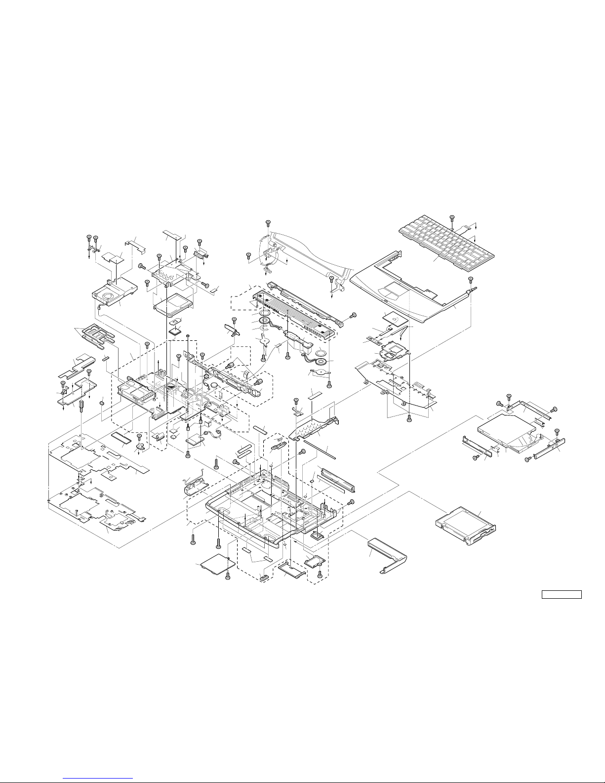
5-1
CHAPTER 5.
EXPLODED VIEWS AND PARTS LIST
NOTE:
• The mechanical parts with no reference number in the
exploded views are not supplied.
• Items marked “ * ” are not stocked since the y are seldom
required for routine service. Some delay should be
anticipated when ordering these items.
• When two or more parts are shown in parallel, use the
part described first as the main part.
• The indication [CH] is used for identification of part type.
• Regarding the boards of this model, the discrete parts
on the boards cannot be replaced. However, Some
connectors can be replaced.
Confidential
PCG-FXA47/FXA49 (AM)
The components identified by mark 0 or
dotted line with mark 0 are critical for safety .
Replace only with part number specified.
Les composants identifiés par une marque
0 sont critiques pour la sécurité.
Ne les remplacer que par une pièce portant
le numéro spécifié.
5-2
Confidential
PCG-FXA47/FXA49 (AM)
Ref.No. Part No. Description Ref.No. Part No. Description
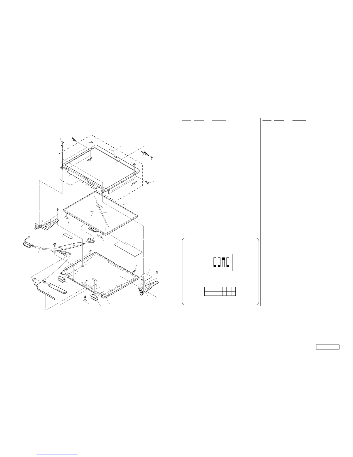
5-1. Main Section
1 X-4623-848-2 [CH]...ASSY BOTTOM (Q)
3 4-640-837-22 DOOR BATTERY
* 8 4-651-706-01 HEATSINK BOTTOM
* 11 4-656-752-01 [CH]...INSULATOR HEATSINK BOTTOM
15 4-643-832-21 DUMMY CARD
18 A-8049-276-A COMPLETE PWB SWX-74
19 X-4623-389-1 ASSY HOOD KEYBOARD Z (P)
20 1-529-287-11 SPEAKER UNIT
22 1-790-639-22 FPC 50PIN (FOR HDD)
24 1-796-184-11 (FXA47)...HDD (DK23CA-20F-20G)
24 1-796-172-11 (FXA49)...HDD (DK23CA-30F-30G)
25 1-476-647-12 KEY BOARD UNIT (US)
26 X-4623-849-2 [CH]...ASSY PALMREST (Q)
27 1-772-529-72 PAD, TOUCH
28 A-8049-275-A COMPLETE PWB CNX-129
* 29 4-651-699-01 BRACKET PAD
* 30 4-651-708-12 BRACKET (HDD)
31 4-640-861-04 BRACKET CD-ROM R
32 1-796-264-11 COMBO DRIVE (UJDA720)
33 X-4623-436-2 ASSY DOOR DVD-RW (PA)
* 34 4-640-860-03 BRACKET (CD-ROM L)
38 4-656-727-01 [CH]...DOOR I/O
39 4-656-735-01 [CH]...FOOT REAR
40 4-651-714-01 DOOR DOCKING CONNECTOR
41 4-656-736-01 [CH]...FOOT FRONT
46 A-8049-270-A COMPLETE PWB PWS-14
48 1-761-380-23 CARD, MODEM
52 1-790-640-11 FPC 50PIN (FOR CD-ROM)
55 4-640-845-11 BUTTON BAY
56 4-644-349-01 LATCH BAY
* 57 4-640-854-01 SPRING BAY
* 58 4-651-850-01 BRACKET BOTTOM
* 59 4-640-857-01 DOOR BATTERY SPRING
60 4-651-698-01 DISPLAY BASE
63 4-651-928-02 COVER BATTERY CONNECTOR
67 4-656-756-01 [CH]...LABEL I/O
* 71 4-641-851-02 SPRING (FDD), PLATE
72 4-657-283-01 [CH]...BRACKET IO
74 4-651-702-01 DOOR DIMM
* 76 4-644-361-01 BRACKET SPK
* 78 4-644-362-11 PLATE PALMREST
81 6-600-065-01 IC MT8LSDT3264HG-10EB1
(PC-100 SO-DIMM (256MB CL2))
81 6-600-097-01 IC HYS64V32220GDL-8-C2
(PC-100 SO-DIMM (256MB CL2))
84 1-960-827-21 HARNESS (2 PIN)
88 A-8058-677-A MAIN BOARD ASSY (∗1)
105 4-641-630-11 COVER BAY HOLE
123 1-790-711-21 FFC (PPK)
124 1-757-767-11 FFC (TP-CNX)
125 1-790-710-11 FFC (SWX-PWS)
* 134 4-645-433-01 BRACKET BAY CONNECTOR
136 4-644-357-01 CUSHION SPK
147 6-701-607-01 (FXA47)...
IC AHM1000AVS3B (Athlon4 1.0GHz)
147 6-702-162-01 (FXA49)...
IC AHM1200AJS3B (Athlon4 1.2GHz)
148 X-4623-561-2 ASSY LATCH DETECTOR
149 1-756-148-11 SECONDARY BATTERY, LITHIUM
155 4-651-701-01 DOOR MODEM
157 4-654-701-01 CUSHION (HD-M2)
161 4-654-019-01 GASKET (AV)
162 4-654-047-01 SHIELD (AV)
163 4-653-936-01 GASKET (HB/M)
164 A-8059-275-A COOLING UNIT-3
165 4-644-667-01 COVER RJ-11
166 4-654-631-01 GUARD SPK
180 4-656-486-01 TAPE CPU (A6)
* 181 4-654-398-01 PLATE GROUND (SH)
182 4-657-164-03 BRACKET WIRE 2
183 4-655-511-01 GASCKET (DRIVE)
184 4-654-776-01 INSULATOR (SCREW)
185 4-654-783-01 SHIELD TAPE (HDD)
186 4-655-042-01 SHIELD SHEET (FAN)
187 4-658-711-01 SHIELD TAPE (FAN)2
188 4-658-542-01 SPACER (KEY BOARD)
190 4-657-629-01 SPRING DRIVE (PA)
191 4-657-049-01 SPRING DRIVE (PA-R)
192 4-658-470-01 [CH]...GASKET (DOCK)
193 4-659-640-01 TAPE (DOCK) J
194 4-659-641-01 SHIELD TAPE (USB) 2J
195 9-885-020-01 CABLE ASSY (RJ-45-CONN)
196 4-653-151-01 SPACER (KBF)
B1 4-641-726-41 SCREW (M2), SPECIAL HEAD
B3 4-644-899-01 SCREW (M2), 0 NUMBER P3 KIND
B4 4-639-112-01 SCREW M2X4
B7 4-644-402-12 SCREW (MBX)
B8 4-641-726-11 SCREW (M2), SPECIAL HEAD
B10 4-652-498-01 +B M2 (NOJI)
B12 4-645-177-01 SCREW (M1.7X3.5)
B14 4-645-497-01 SCREW (M2.6), CROSS (HOLE) BIND
B15 4-635-301-01 SCREW M3X4
B17 7-622-205-05 NUT M2 TYPE2
B31 4-645-214-11 GRIP, M2
B32 7-621-772-68 SCREW +B 2X12
B33 4-642-852-21 +B M2
B38 4-651-989-01 SPACER (MBX)
800 Refer to section “5-2.FDD Section”
∗1 When replacing the LCD or the MBX-61 board,
confirm the DIP switch position beforehand.
(Refer to LCD Section.)
Confidential
PCG-FXA47/FXA49 (AM)5-3 5-4
166
163
41
Supplied
with 88
Supplied
with 19
Supplied
with 88
B3
161
165
193
192
162
161
C
B8
B3
B3
B8
B8
78
24
B15
B15
46
E
E
F
F
I
D
C
N
N
I
J
H
H
A
B
B
A
K
K
L
L
D
52
B4
B4
B1
B32
B8
B4
15
76
76
20
123
20
18
19
60
38
183
67
40
3
59
74
164
58
26
25
27
28
124
125
29
81
B1
B33
B33
B1
B1
B8
B8
22
B1
B7
B8
B14
B14
B14
B8
136
136
11
8
134
149
194
195
63
71
162
J
30
185
186
147
88
182
180
188
B8
48
84
148
1
M
B1
B1
B8
B8
157
B38
B31
B17
M
55
155
B8
105
39
57
56
181
187
184
184
800 (Refer to Page 5-5.)
34
190
191
32
31
B10
B10
B10
33
B12
B12
B1
701
(Refer to Page 5-10.)
Supplied
with 88
Supplied
with 1
196
72
Confidential
PCG-FXA47/FXA49 (AM)
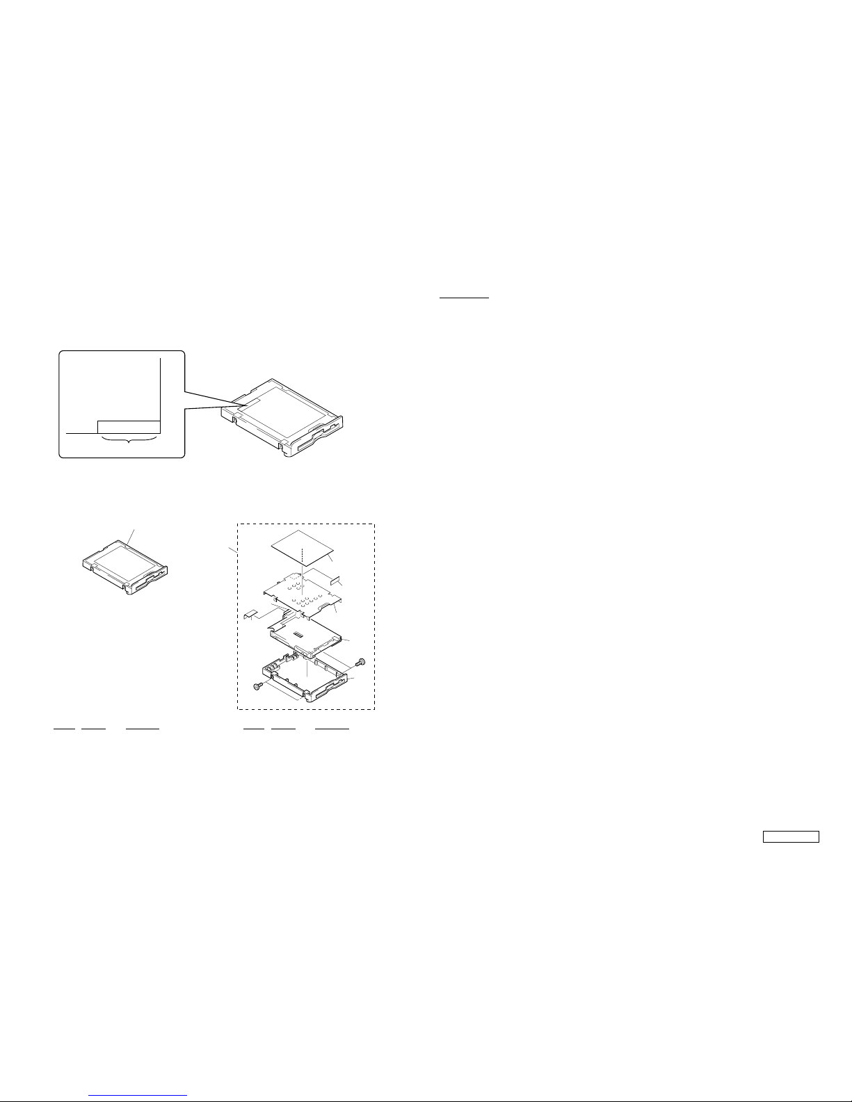
5-2. FDD Section
How to use properly the FDD repair parts.
Types of service to be provided are different depending on the serial No. of the FDD in use.
The service types are shown below depending on the serial No. that is printed in the bottom right of the FD label.
[Serial No. : 4-656-805-0*] [Serial No. : 4-641-763-3*]
800
803
802
B1
B1
801
805
804
807
806
800
Ref.No. Part No. Description
800 A-8025-674-A FDD UNIT ASSY (TN-CH)
Ref.No. Part No. Description
800 A-8048-966-A ASSY BAY FD (TE)
801 4-640-828-01 PLATE FDD
802 1-796-231-11 FDD (FD-07-7760)
803 X-4623-835-1 ASSY BOTTOM FDD Z (TCY3)
804 1-790-641-11 FPC 50PIN (FOR FDD)
805 4-641-629-01 INSULATOR FDD
806 4-641-763-31 LABEL FD
807 4-644-053-01 SPACER FDD
B1 4-646-807-01 0 PLATE M2.5 (FDD)
Serial No.
X-XXX-XXX-XX
Label FD
5-5 5-6
MEMO
Confidential
PCG-FXA47/FXA49 (AM)5-7 5-8
Ref.No. Part No. Description
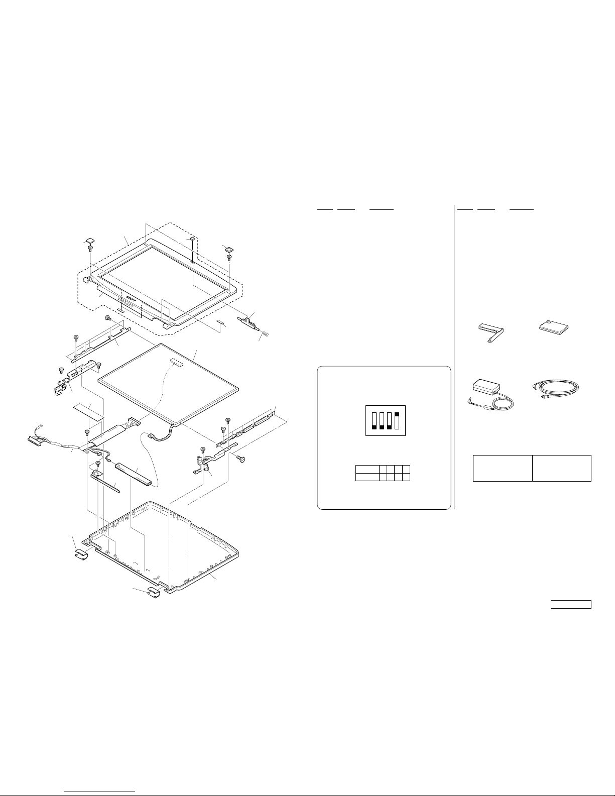
5-3. LCD Section (FXA49 Model) – Made by NE –
Ref.No. Part No. Description
NOTE :
Set the DIP switch on the MBX-61 board (Main board) to match
with the LCD (A-8023-519-A) that is used in this computer.
The upper position where ON indication is shown is the
ON position . The lower position is the OFF position.
1234
1101
0 : ON 1: OFF
No.
ON/OFF
1234
ON
B30
B22
B22
B8
224
221
226
235
203
234
234
206
208
224
223
214
207
212
213
213
219
201
225
222
229
228
202
231
237
231
220
B23
B23
B8
238
236
Supplied
with 203
201 1-476-316-11 INVERTER UNIT
202 X-4623-380-1 HINGE LEFT 15
203 X-4623-448-2 ASSY HOU, BEZEL 15SA-Z
206 4-637-902-31 LATCH
207 A-8023-519-A ASSY LCD XGA 15NE (S)
208 4-637-903-01 SPRING LATCH
212 X-4624-622-1 ASSY HOU, DISPLAY 15SA-Z
213 4-642-762-31 COVER HINGE (15)
214 4-660-598-11 LABEL ID (U)
219 1-757-604-11 PWB, FLEXIBLE PRINT (SINGLE)
220 4-642-755-01 BRACKET LCD (DL) 15
221 4-642-756-01 BRACKET LCD (BL) 15
222 4-642-757-01 BRACKET LCD (DR) 15
223 4-642-758-01 BRACKET LCD (BR) 15
224 4-646-217-11 COVER SCREW SIDE (15)
225 4-635-277-22 COVER SCREW LOWER
226 4-643-549-12 COVER SCREW SHAFT
228 X-4623-381-1 HINGE RIGHT 15
229 4-643-366-11 EDGE GUARD HINGE (15)
231 4-643-837-01 SHIELD (LCD)
234 4-635-276-22 COVER SCREW UPPER
235 4-642-760-12 CUSHION CENTER
236 4-658-280-01 SHIELD TAPE (LCD)
237 1-961-018-81 HARNESS,LCD (XGA-F-N)
238 4-650-831-01 SHIELD TAPE (SK)
B8 4-641-726-11 SCREW (M2), SPECIAL HEAD
B22 4-641-726-81 SCREW (M2), SPECIAL HEAD
B23 4-644-165-01 SCREW (M2.6X4), 0 PLATE P1 MAIN
B30 4-643-550-01 +P 2.6X6 LOCK PRECISION TYPE3
Confidential
PCG-FXA47/FXA49 (AM)
Ref.No. Part No. Description
5-4. LCD Section (FXA47 Model) – Made by AC –
Ref.No. Part No. Description
NOTE :
∗1 When replacing the LCD or the MBX-61 board, confirm
the DIP switch position beforehand.
Set the DIP switch on the MBX-61 board (Main board) to match
with the LCD (A-8023-466-A) that is used in this computer.
The upper position where ON indication is shown
is the ON position . The lower position is the OFF
position.
To replace the LCD during repair, be sure to use
A-8023-466-A.
1234
1110
0 : ON 1: OFF
No.
ON/OFF
5-9 5-10
1234
ON
301 1-476-318-21 INVERTER UNIT
302 X-4623-378-1 HINGE LEFT MV
303 X-4623-409-3 ASSY HOU, BEZEL 14SA-Z
304 4-635-277-22 COVER SCREW LOWER
305 4-635-276-22 COVER SCREW UPPER
306 4-637-902-31 LATCH
307 A-8023-466-A ASSY LCD XGA 14AU (S) (∗1)
308 4-637-903-01 SPRING LATCH
309 X-4623-379-1 HINGE RIGHT MV
312 X-4623-458-1 ASSY HOU, DISPLAY 14FV-Z
313 4-642-762-31 COVER HINGE (15)
314 4-660-598-21 LABEL ID (U)
317 1-757-605-11 PWB, FLEXIBLE PRINT (SINGLE)
319 4-654-966-01 SHEET (BEZEL), ADHESIVE
* 322 4-644-163-11 BRACKET LCD LEFT 14 (SA)
* 323 4-644-164-11 BRACKET LCD RIGHT 14 (SA)
325 4-642-760-12 CUSHION CENTER
326 1-961-018-81 HARNESS, LCD (XGA-F-N)
327 4-650-831-01 SHIELD TAPE (SK)
B8 4-641-726-11 SCREW (M2), SPECIAL HEAD
B20 7-628-254-00 SCREW +PS 2.6X5
B22 4-658-316-01 ACE (M2), +B LOCK
312
302
307
308
306
305
325
303
B22
B8
304
B8
B8
B20
B20
B22
B8
B8
B8
309
314
322
323
313
313
327
B8
326
B8
317
301
319
Supplied
with 303
ACCESSORIES
************
701 A-8048-965-A ASSY WEIGHT SAVER (Z)
(Refer to Page 5-4.)
0702 1-476-342-22 ADAPTOR, AC
703 1-528-934-21 BATTERY PACK, LITHIUM ION
704 1-575-875-51 CORD, CONNECTION
0 1-757-562-21 CORD, POWER
4-661-889-11 QUICK START, AMSTEL
4-661-884-11 SPECIFICATIONS SHEET
701
Weight saver (1)
702
AC adaptor (1)
703
Battery pack (1)
704
Video cable (1)
The components identified by
mark 0 or dotted line with mark
0 are critical for safety.
Replace only with part number
specified.
Les composants identifiés par
une marque 0 sont critiques
pour la sécurité.
Ne les remplacer que par une
pièce portant le numéro spécifié.
Confidential
PCG-FXA47/FXA49 (AM)5-11 5-12
(END)
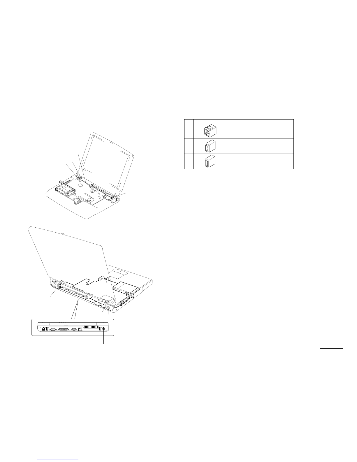
5-5. Connector Section (CH Type only)
∗Before replacing the connector of
reference number 901, 902 and
903, remove the bracket I/O.
901 1-779-745-21 [CH]...JACK, DC
DC IN connector
902 9-885-018-97 [CH]...CONNECTOR (1.2MM), USB
USB connector
903 9-885-018-98 [CH]...CONNECTOR (1.6MM), USB
USB connector
Ref.No. Fig. Part No. Description
901
903
902
903
901
902
901
Bracket I/O
903
902
∗ Among the parts that are used on the boards of this model, only the connectors
that are show in the list can be replaced.
(The parts other that the specified connectors cannot be replaced.)

VAIO® Notebook
Quick Start
PCG-FXA40 Series


Contents
Welcome.......................................................5
Unpacking Your Notebook .........................................7
Registering Your Computer ........................................9
Setting Up Your Dial-Up Connection .......................10
Setting Up Your VAIO Notebook..............13
Locating Controls and Connectors ............................14
Connecting a Power Source ......................................19
Starting Your Notebook ............................................25
Shutting Down Your Notebook.................................26
Using Power Saving Modes ......................................27
Adding Memory .........................................29
Precautions and Procedures.......................................30
Removing a Memory Module ...................................32
Installing a Memory Module.....................................34
Viewing the Amount of Memory ..............................35
About the Software on Your Notebook ...37
Software Overview....................................................38
Application, Driver, and System Recovery CDs.......45
Using Your Recovery CDs........................................46
3

VAIO® Notebook Quick Start
Troubleshooting........................................53
Troubleshooting Your Notebook .............................. 54
Troubleshooting the LCD Screen ............................. 57
Troubleshooting the Mouse and Touchpad .............. 57
Getting Help...............................................61
Support Options ........................................................ 62
Software Support Information .................................. 64
4

Welcome
Congratulations on your purchase of the Sony VAIO® all-in-one
notebook. Sony has combined leading-edge technology in audio, video,
computing, and communications to provide you with state-of-the-art
personal computing.
Features
For a complete description of the specifications of your VAIO® notebook, refer to the
✍
Specifications flyer supplied with your notebook.
Exceptional performance* — Your notebook includes a mobile AMD
❑
processor featuring PowerNow!™ technology
modem.
Portability — Rechargeable battery pack provides hours of use without
❑
‡
†
and a V.90-compatible
AC power.
Sony audio and video quality — High-quality MPEG1/MPEG2 video,
❑
which supports full-screen display and enables you to take advantage of
today’s advanced multimedia applications, games, and entertainment
software.
Multimedia features — Enjoy the stereo speakers or use headphones (not
❑
supplied) to listen to audio and video CDs.
Microsoft® Windows® operating system — Your system includes the
❑
latest Microsoft® Windows® operating system.
* To combine performance and portability, Sony implemented speed-controlling technology
designed to maximize battery life during mobile computer use. Windows® reported actual
CPU speed may not reflect the maximum CPU speed.
† Processor speed may be reduced under certain conditions.
‡ Actual upload and download speeds may vary due to line conditions, Internet Service Pro-
vider (ISP) support, and government regulations.
5

VAIO® Notebook Quick Start
Communications — Access popular online services, send e-mail, browse
❑
the Internet, and use fax features.
Optical disc drive (CD-RW/DVD or DVD-ROM) — The CD-RW/DVD
❑
Combo Drive utilizes a new optical storage technology that combines the
features of both a CD-RW drive and DVD-ROM drive, providing increased
storage capacity and a rich multimedia computing experience. Optical drives
play DVD-ROM, CD-ROM, CD-RW, and CD-R discs. (The CD-RW/DVD
Combo Drive is available on selected models only.)
Your notebook’s optical disc drive and other parts may differ depending on the model
✍
you purchased.
6
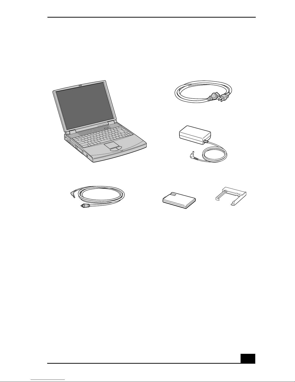
Unpacking Your Notebook
Remove the following hardware items from the box:
Unpacking Your Notebook
Main unit
Video cable Rechargeable
*
Power cord
AC adapter
battery pack
Weight saver
* Removable floppy disk drive is in the multipurpose bay.
Documents
VAIO® Notebook Quick Start — Contains information on unpacking and
❑
setting up your notebook, the features of your notebook, the applications
included with your system, and how to solve common problems.
VAIO® Notebook User Guide — A searchable online help file that contains
❑
detailed information on how to use your new notebook. Press Start on the
Windows® taskbar, select VAIO Help and Support, and click VAIO User
Guide to open this file.
Microsoft® Windows® manual — Explains how to use the basic features
❑
of the Windows operating system.
7

VAIO® Notebook Quick Start
VAIO® Notebook Notes on Use — Explains notes on use and offers
❑
safety tips.
VAIO® Notebook Specifications flyer — Details the hardware
❑
specifications for your notebook.
Software CDs
Microsoft® Word — Enables you to reinstall Microsoft Word to the VAIO
❑
computer you purchased, if the application becomes corrupted or is erased.
Recovery CDs
Application Recovery CD(s) — Enables you to reinstall individual
❑
applications if they become corrupted or are erased.
Driver Recovery CD(s) — Enables you to reinstall individual device
❑
drivers if they become corrupted or are erased.
System Recovery CD(s) — Enables you to restore the operating system and
❑
software that shipped with your computer, to its original factory settings, if
they become corrupted or are erased.
Other
Packet containing special product offers
❑
Limited Warranty Card
❑
8

Registering Your Computer
Registering Your Computer
Take advantage of Sony’s commitment to quality customer support and receive
these benefits by registering your notebook:
Sony Customer Support — Talk to a Support Representative to
❑
troubleshoot problems you may have with your notebook.
Limited Warranty — Protect your investment. See the Warranty Card for
❑
more details.
You are prompted to register your computer the first time you turn on the unit. Follow
✍
the on-screen instructions to complete the registration process. If you are not able to
register your computer during the first session, you are provided with additional
registration opportunities later.
9
VAIO® Notebook Quick Start
Setting Up Your Dial-Up Connection
This section describes the basic steps for setting up your dial-up connection. The
Connection Wizard guides you through the process of connecting to the Internet
and then choosing an Internet Service Provider (ISP) or setting up an existing
account.
Setting up your dial-up connection
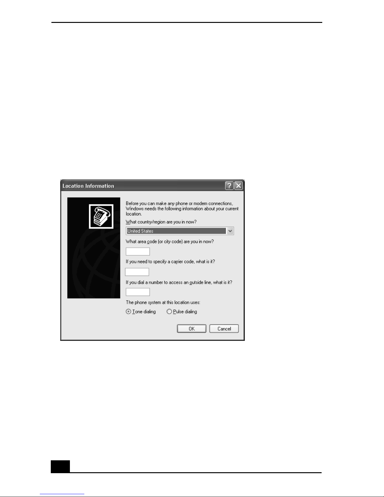
1 Click Start, point to All Programs, Accessories, Communications, and then
click New Connection Wizard. The Location Information window appears.
Location Information window
2 Follow the instructions on-screen and then click OK to continue. The Phone
and Modem Options window appears.
10
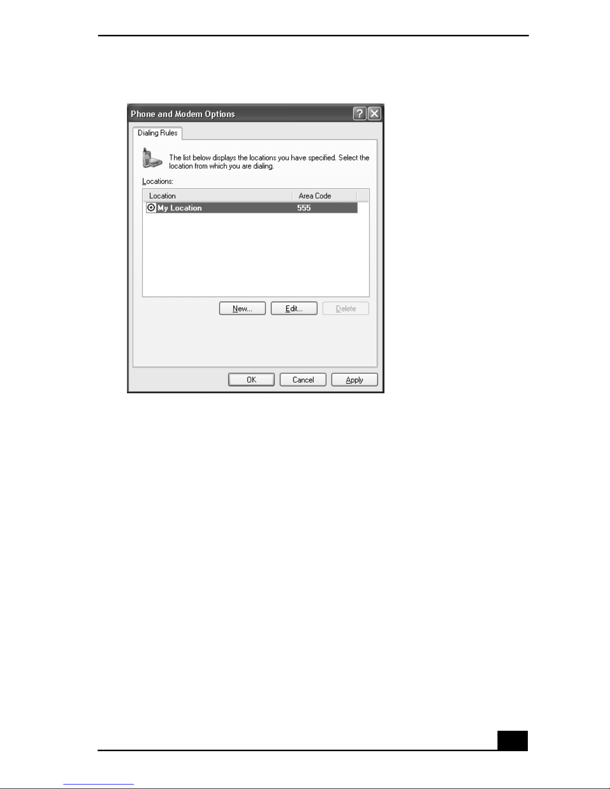
Phone and Modem Options window
Setting Up Your Dial-Up Connection
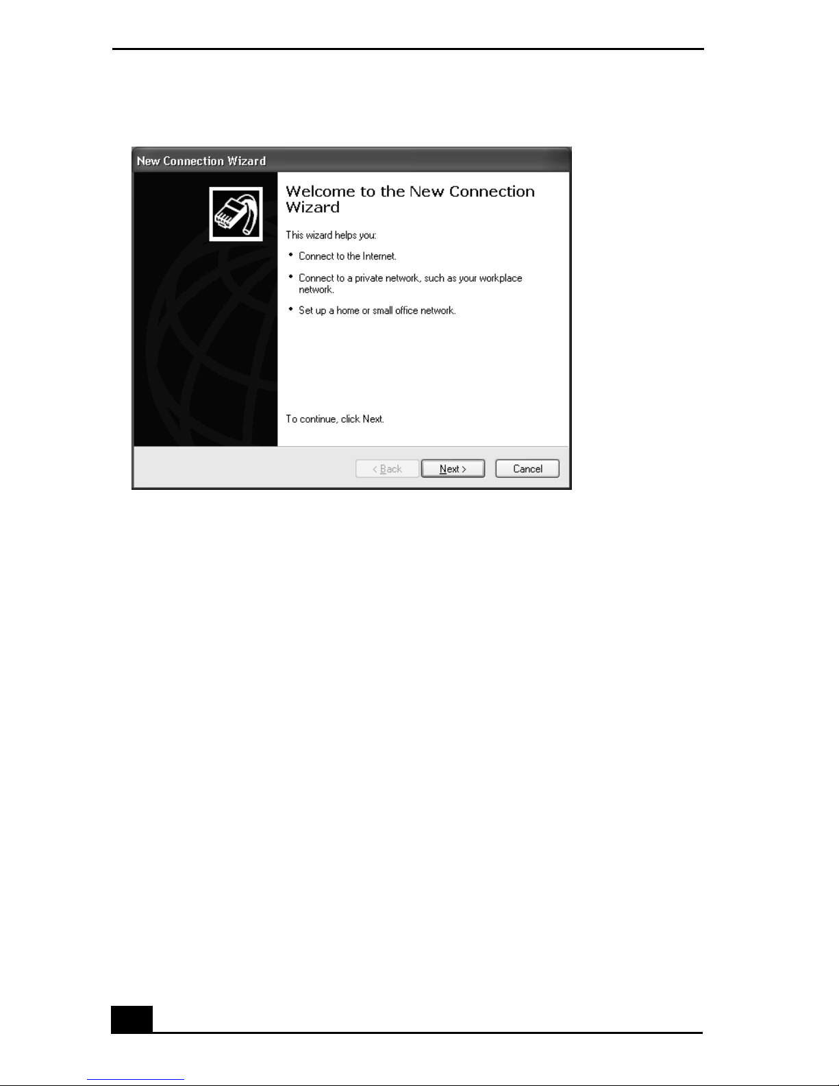
3 Select the location from where you are dialing and then click OK. The New
Connection Wizard window appears.
11
VAIO® Notebook Quick Start
New Connection Wizard window
4 Follow the on-screen instructions to finish setting up your dial-up
connection.
12

Setting Up Your VAIO Notebook
This section provides you with some essential information to familiarize
you with your VAIO computer and assist you with some of its fundamental
functions.
Locating Controls and Connectors
❑
Connecting a Power Source
❑
Starting Your Notebook
❑
Shutting Down Your Notebook
❑
Using Power Saving Modes
❑
13
 Loading...