

Sony VAIO PCG-FX777, VAIO PCG-FX877 Service Manual

Confidential
PCG-FX777/FX877
SERVICE MANUAL
NOTEBOOK COMPUTER
9-872-288-01
For American Area
Latin Model
Lineup : PCG-FX777
PCG-FX877
S400
Illust : PCG-FX877
Ver 1-2001J
All the supplementary
information are attached
at the end of data files.
Update List

— 2 —
Information in this document is subject to change without notice.
Sony and VAIO are trademarks of Sony. Intel logo and Intel Inside
logo are registered trademarks of Intel Corporation. Pentium MMX
is a trademark of Intel Corporation. Microsoft, MS-DOS, Windo ws,
the W indows 95 and W indows 98 log o are trademarks of Microsoft
Corporation.
All other trademarks are trademarks or registered trademarks of
their respective owners. Other tr ademarks and trade names may be
used in this document to refer to the entitles claiming the marks and
names or their produces. Sony Corporation disclaims any proprietary
interest in trademarks and trade names other than its own.
Service and Inspection Precautions
1. Obey precautionary markings and instructions
Labels and stamps on the cabinet, chassis, and components identify areas
requiring special precautions. Be sure to observe these precautions, as well
as all precautions listed in the operating manual and other associated
documents.
2. Use designated parts only
The set’s components possess important safety characteristics, such as
noncombustibility and the ability to tolerate large voltages. Be sure that
replacement parts possess the same safety characteristics as the originals.
Also remember that the 0 mark, which appears in circuit diagrams and
parts lists, denotes components that have particularly important safety
functions; be extra sure to use only the designated components.
3. Always follow the original design when mounting
parts and routing wires
The original layout includes various safety features, such as inclusion of
insulating materials (tubes and tape) and the mounting of parts above the
printer board. In addition, internal wiring has been routed and clamped so
as to keep it away from hot or high-voltage parts. When mounting parts or
routing wires, therefore, be sure to duplicate the original layout.
4. Inspect after completing service
After servicing, inspect to make sure that all screws, components, and wiring
have been returned to their original condition. Also check the area around
the repair location to ensure that repair work has caused no damage, and
confirm safety.
5. When replacing chip components...
Never reuse components. Also remember that the negati ve side of tantalum
capacitors is easily damaged by heat.
6. When handling flexible print boards...
•The temperature of the soldering-iron tip should be about 270C.
•Do not apply the tip more than three times to the same pattern.
•Handle patterns with care; never apply force.
Caution: Remember that hard disk drives are easily damaged by
vibration. Always handle with care.
Caution Markings for Lithium/Ion Battery - The following or similar
texts shall be provided on battery pack of equipment or in both the
operating and the service instructions.
CAUTION: Danger of explosion if battery is incorrectly replaced.
Replace only with the same or equivalent type recommended by
the manufacturer. Discard used batteries according to the
manufacturer’s instructions.
CAUTION: The battery pack used in this de vice may present a fire
or chemical burn hazard if mistreated. Do not disassemble, heat
above 100°C (212°F) or incinerate.
Dispose of used battery promptly.
Keep away from children.
CAUTION: Changing the back up battery.
• Overcharging, short circuiting, reverse charging, multilation or
incineration of the cells must be avoided to prevent one or mor e of
the following occurrences; release of toxic materials, release of
hydrogen and/or oxygen gas, rise in surface temperature.
• If a cell has leaked or vented, it should be replaced immediately
while avoiding to touch it without any protection.
ATTENTION AU COMPOSANT AYANT RAPPORT
À LA SÉCURITÉ!
LES COMPOSANTS IDENTIFÉS P AR UNE MARQUE 0 SUR LES
DIAGRAMMES SCHÉMA TIQUES ET LA LISTE DES PIÈCES SONT
CRITIQUES POUR LA SÉCURITÉ DE FONCTIONNEMENT. NE
REMPLACER CES COMPOSANTS QUE PAR DES PIÈSES SONY
DONT LES NUMÉROS SONT DONNÉS DANS CE MANUEL OU
DANS LES SUPPÉMENTS PUBLIÉS PAR SONY.
Confidential
PCG-FX777/FX877 (AM)

— 3 —
TABLE OF CONTENTS
CHAPTER 1. REMOVAL
1-1. Flowchart ......................................................................... 1-1
1-2. Main Electrical Parts Location Diagram ......................... 1-1
1-3. Removal........................................................................... 1-2
1. Assy Hood Keyboard, Keyboard Unit ............................. 1-2
2. DC-Fan, Combination Drive............................................1-2
3. Combination Drive........................................................... 1-3
4. HDD, Door Battery.......................................................... 1-4
5. Assy Palmrest, Pad Touch, CNX-125 Board,
Plate Palmrest, Bracket Pad ............................................. 1-4
6. Display Assy, Cover Hinge.............................................. 1-5
7. PWS-13 Board, Latch Detector ...................................... 1-6
8. PC Card Connector, Card Modem,
MBX-49 Board, Bracket I/O, Lithium Battery................ 1-6
9. Speaker Unit, SWX-73 Board ......................................... 1-7
10. SO-DIMM........................................................................ 1-7
11. Card Modem (Removing from the bottom) ..................... 1-8
12. LCD Section
(FX877 Model) – Made by TS – .................................... 1-9
1. Assy Housing Bezel, LCD Unit ................................... 1-9
2. Inverter Unit, FPC, Assy Housing Display,
Harness LCD.............................................................. 1-10
13. LCD Section
(FX777 Model) – Made by HI – ................................... 1-11
1. Assy Housing Bezel (14 inch) ................................... 1-11
2. Bracket LCD Left, Bracket LCD Right,
LCD Unit (14 inch) .................................................... 1-12
3. FPC, Inverter Unit, Assy Housing Display,
Harness LCD.............................................................. 1-12
1-4. Replacing the CPU ........................................................ 1-13
1. Socket type 1,2............................................................... 1-13
1. Removing the CPU .................................................... 1-13
2. Installing the CPU ...................................................... 1-13
2. Socket type 3.................................................................. 1-14
1. Removing the CPU .................................................... 1-14
2. Installing the CPU ...................................................... 1-14
1-5. DIP Switch Setting of the MBX-49 Board .................... 1-15
(to 1-15)
Section Title Page
Confidential
Section Title Page
CHAPTER 2. SELF DIAGNOSTICS......................... 2-1
(to 2-1)
CHAPTER 3. BLOCK DIAGRAM............................... 3-1
(to 3-2)
CHAPTER 4. FRAME HARNESS DIAGRAM........ 4-1
(to 4-2)
CHAPTER 5. EXPLODED VIEWS AND
PARTS LIST............................................5-1
5-1. Main Section .................................................................... 5-2
5-2. FDD Section .................................................................... 5-5
5-3. LCD Section (FX877 Model) – Made by TS – ............... 5-7
5-4. LCD Section (FX777 Model) – Made by HI –................ 5-9
5-5. Connector Section (CH Type Only) ............................... 5-11
(to 5-12)
PCG-FX777/FX877 (AM)

MEMO
1-1
Confidential
PCG-FX777/FX877 (AM)
CHAPTER 1.
REMOVAL
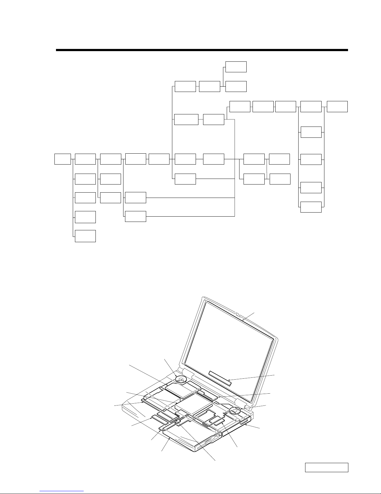
1-1. Flowchart
• P XX means pages that appears in this manual.
• Remember that hard disk drives are easily damaged by vibration. Always handle with care.
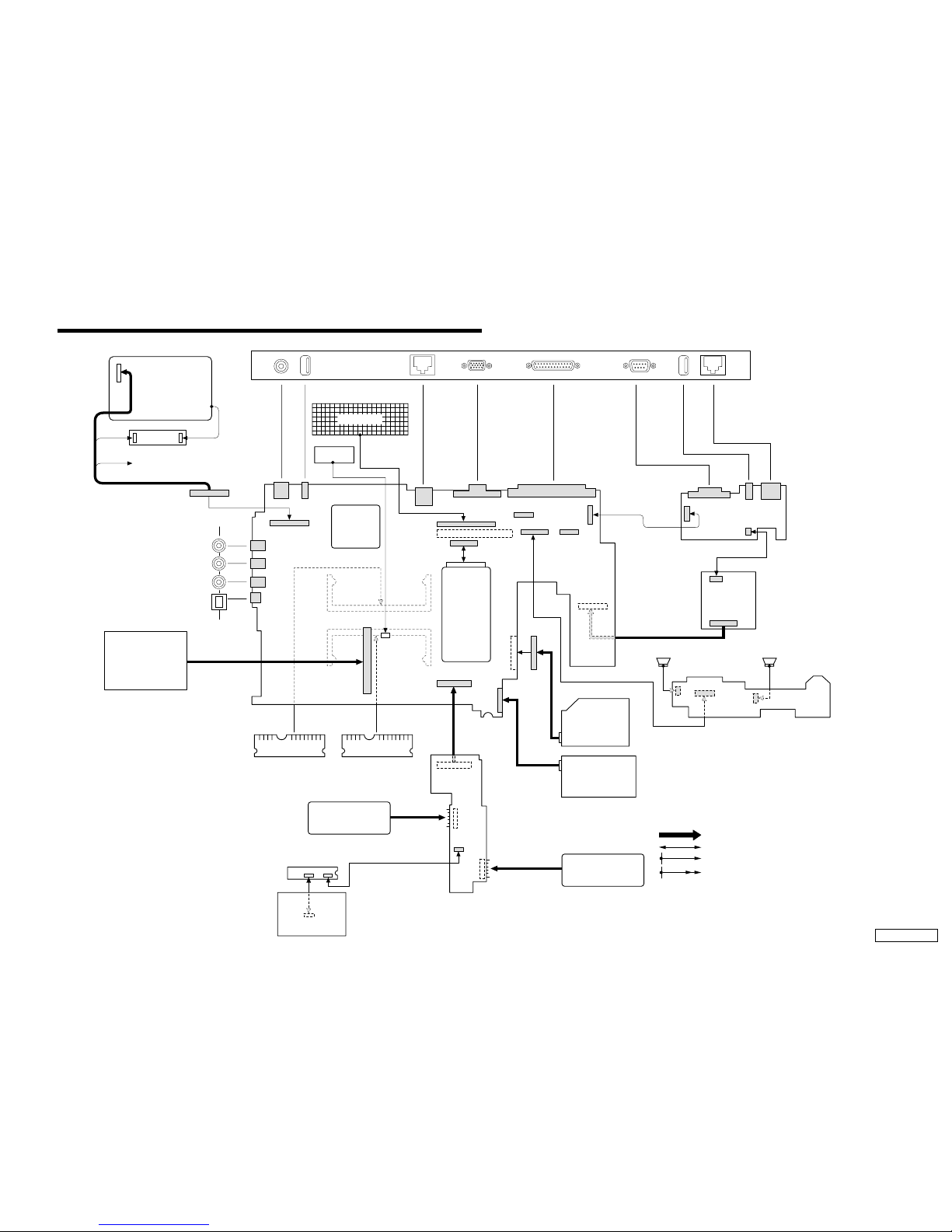
1-2. Main Electrical Parts Location Diagram
POWER
OFF
ASSY
HOOD
KEYBOARD
SO-DIMM
BATTERY
PACK
CARD
MODEM
KEYBOARD
UNIT
P 1-2P 1-2
P 1-7P 1-7
P 1-7
P 1-5
P 1-8
P 1-4
P 1-2
P 1-3
P 1-6
P 1-6
ASSY
P ALMREST
P 1-2
P 1-3
P 1-3
DC-FAN
PC CARD
CONNECTOR
FDD
SPEAKER
UNIT
DOOR
BATTERY
SWX-73
BOARD
P 1-5
DISPLAY
ASSY
P 1-6
LITHIUM
BATTERY
P 1-6
FPC
INVERTER
UNIT
ASSY
HOUSING
DISPLAY
ASSY
HOUSING
BEZEL
COMBINATION
DRIVE
LCD
UNIT
PWS-13
BOARD
P 1-6
P 1-6
HDD
∗P 1-9
(P 1-11)
∗P 1-9
(P 1-11)
∗P 1-10
(P 1-12)
∗P 1-10
(P 1-12)
∗P 1-10
(P 1-12)
∗P 1-10
(P 1-12)
HARNESS
LCD
BRACKET
LCD LEFT
(P 1-12)
BRACKET
LCD RIGHT
(P 1-12)
P 1-4
PLATE
PALMREST
P 1-4
BRACKET
PAD
P 1-4
PAD
TOUCH
CNX-125
BOARD
P 1-4
CARD
MODEM
LATCH
DETECTOR
BRACKET
I/O
MBX-49
BOARD
P 1-6
COVER
HINGE
∗ : FX877 Model
( ) : FX777 Model
LCD Unit
Inverter Unit
Speaker Unit
Combination Drive
(CD-RW/DVD-ROM)
PWS-13 Board
FD Drive
CNX-125 Board
MBX-49 Board
Speaker Unit
DC Fan
HDD
SWX-73 Board
Pad Touch
Card Modem
1-2
Confidential
PCG-FX777/FX877 (AM)
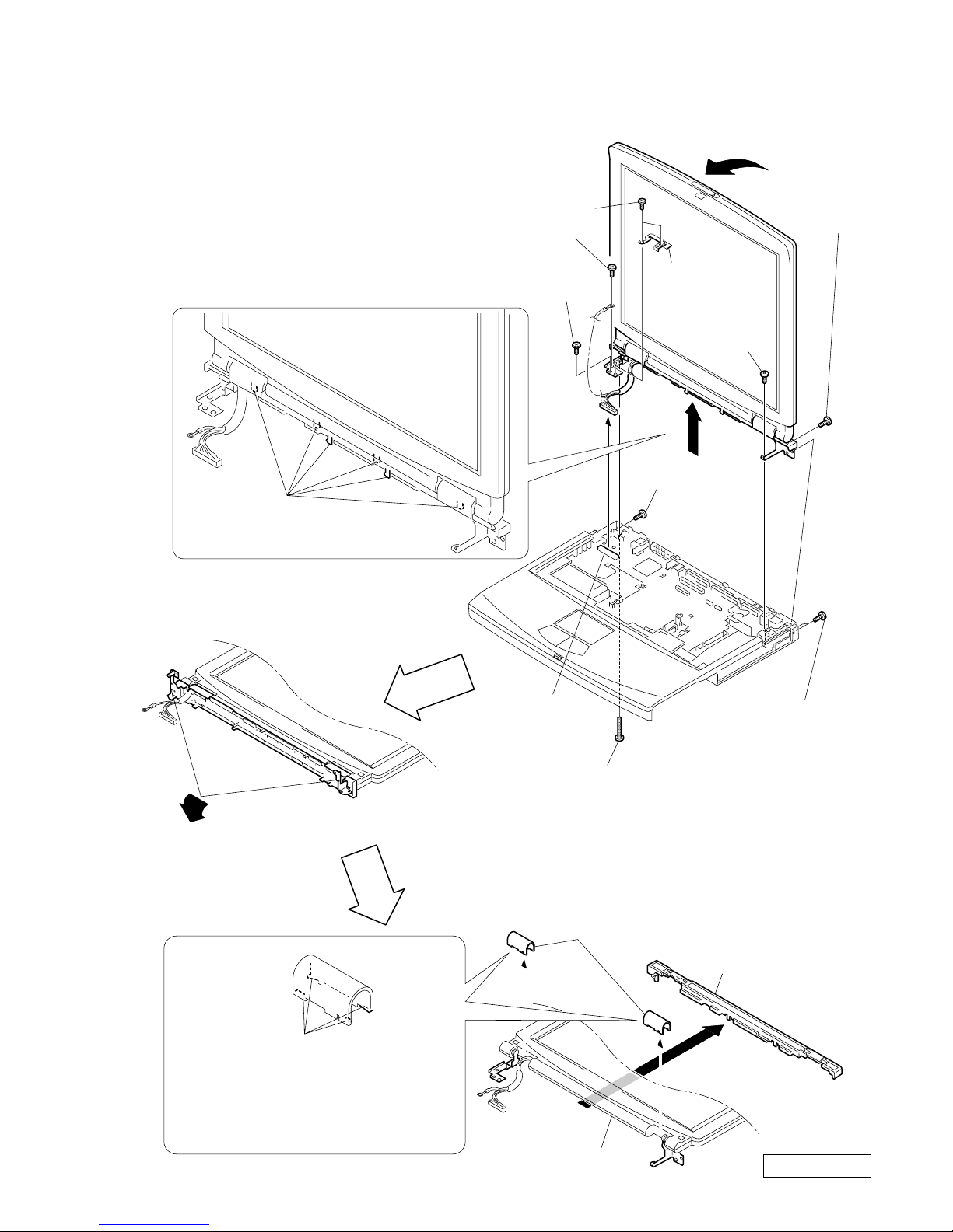
1-3.Removal
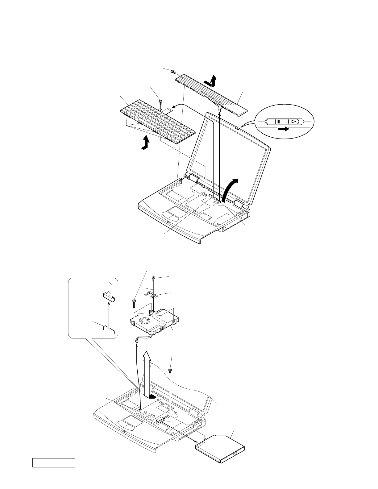
1. Assy Hood Keyboard, Keyboard Unit
2. DC-Fan, Combination Drive
6Assy Hood Keyboard
7
9
5
q;Keyboard Unit
Four Claws
MBX-49 Board
CN2004
MBX-49 Board
CN1902
3Screw M2X4 Special Head (Black)
8Screw M2X4 Special Head (Black)
1
2
4Pull it up sliding it to the right.
qaCombination Drive
7DC Fan
q;
9Screw M2X6 Special Head (Gold)
2+B M2 (X2) (Gold)
5Screw (M2) 0 Number P3 Kind (X4) (Black)
3Plate ground
MBX-49
Board
CN701
8
4
1
MBX-49 Board
CN102
6
1-3
Confidential
PCG-FX777/FX877 (AM)
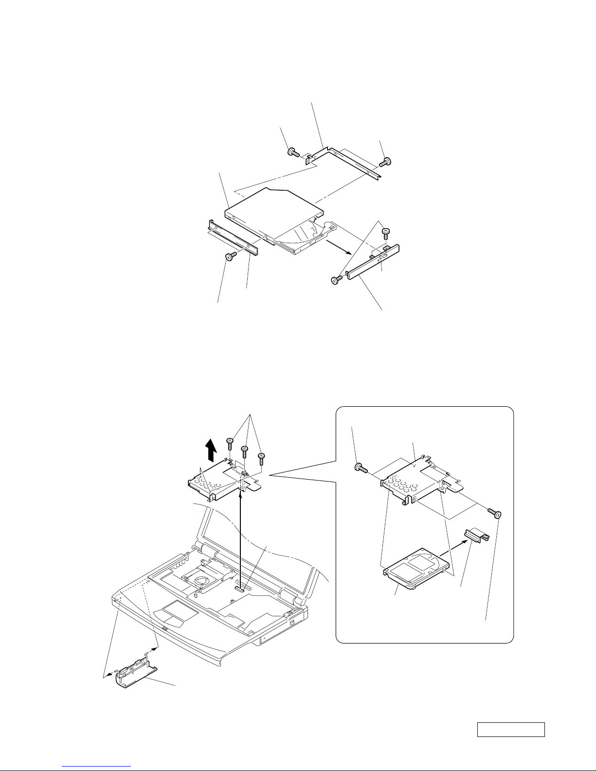
3. Combination Drive
4. HDD, Door Battery
Claw
7Assy Door DVD-RW (PA)
8COMBO Drive
5Bracket CD-ROM R
2Bracket (CD-ROM L)
3+B M2 (NOJI) (X2) (Gold)
1+B M2 (NOJI) (X2) (Gold)
4+B M2 (NOJI) (X2)
(Gold)
6Screw (M1.7X3.5) (X3) (Black)
3
2FPC 50Pin
(for HDD)
4Door Battery
1Screw M2X6 Special Head (X6) (Gold)
1Screw M3X4 (X2) (Gold)
2Screw M3X4 (X2) (Gold)
3Bracket HDD
4FPC 50Pin
(for HDD)
5HDD
MBX-49 Board
CN2201
1-4
Confidential
PCG-FX777/FX877 (AM)
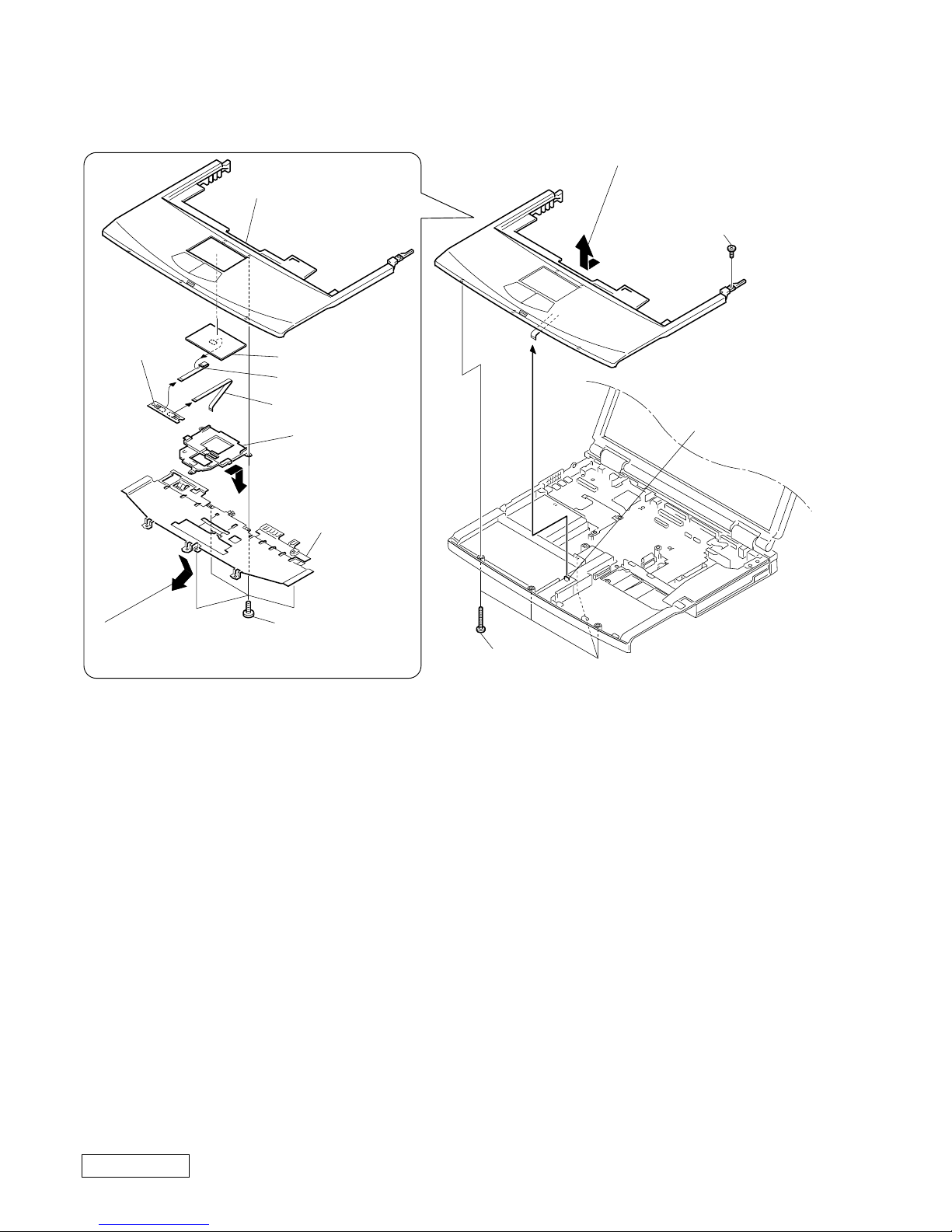
5. Assy Palmrest, Pad Touch, CNX-125 Board, Plate Palmrest, Bracket Pad
Assy Palmrest
1Screw M2X4
Special Head
(Black)
4
1M2X4 Special
Head (x4) (Black)
5Bracket Pad
9Pad, Touch
8FPC (TP-CNX)
6FPC (SWX-PWS)
3Plate
Palmrest
7CNX-125
Board
2Screw (M2),
0 Number P3 Kind (X4) (Black)
PWS-13 Board
CN4004
3Pull it to the front slightly
and raise to remove it.
2
Move down the front
portion slightly
downward and then pull it out.
4Remove by pressing
to rear.
1-5
Confidential
PCG-FX777/FX877 (AM)
6. Display Assy, Cover Hinge
Four Claws
qfCover Hinge
qhDisplay Base
qg
Display Assy
qaM2X6 Special
Head (Gold)
8Screw (M2), 0 Number P3 Kind (Black)
9Screw M2X6 Special
Head (Gold)
5Screw M2.6
Cross (Hole)
Bind (Black)
7Screw M2.6
Cross (Hole)
Bind (Black)
qs
2
6Screw M2.6 Cross
(Hole) Bind (X2) (Black)
q;Screw +B 2X12 (Silver)
Six Claws
MBX-49 Board
CN701
4Plate ground
3+B M2 (X2) (Gold)
qdClose simultaneously both left and right hinges approximately 90°
in the direction of the arrow.
Note : To remove the cover hinge, bend
slightly the center of the display
base facilitates the removal work.
1Stand the LCD upright
to the MBX-49 board.
1-6
Confidential
PCG-FX777/FX877 (AM)
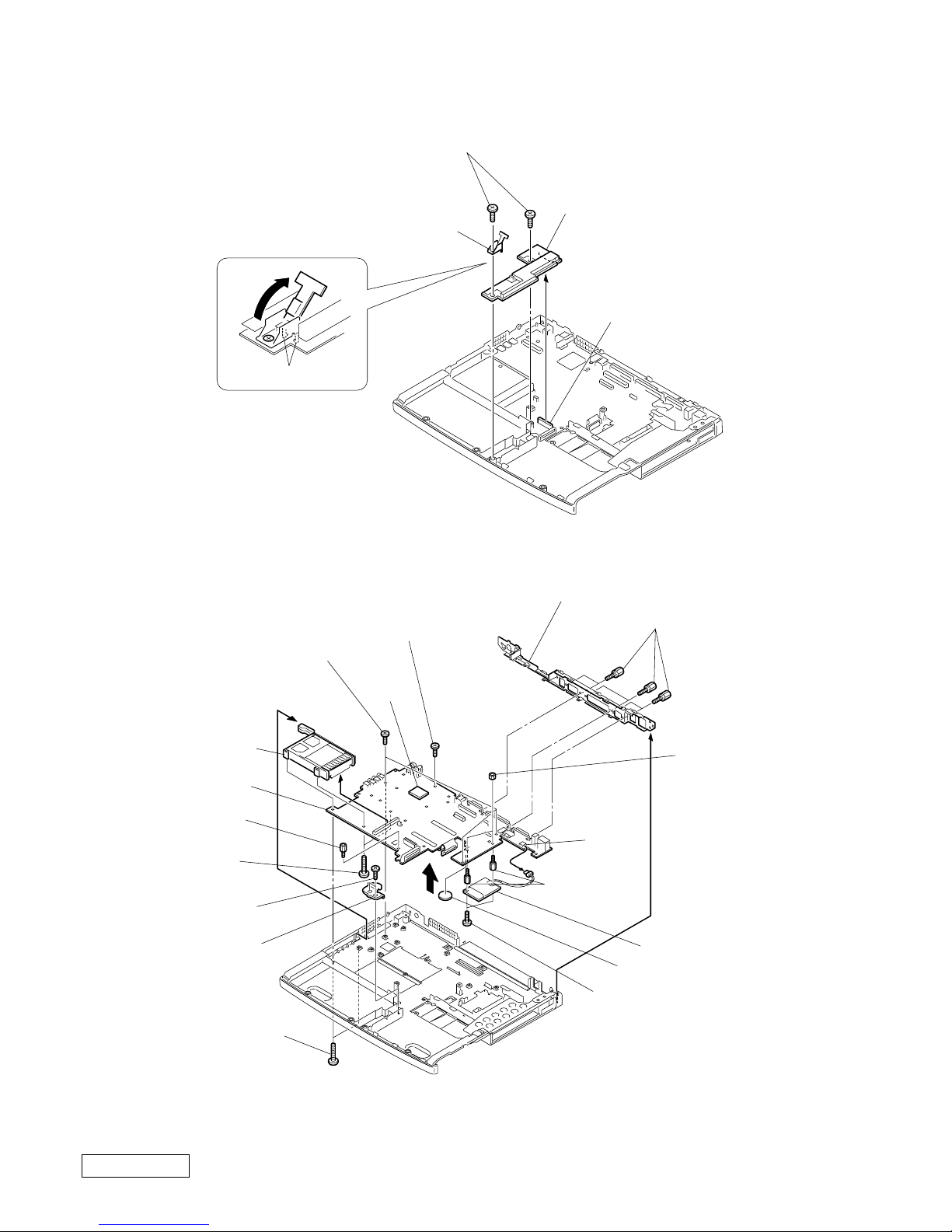
7. PWS-13 Board, Latch Detector
8. PC Card Connector, Card Modem, MBX-49 Board, Bracket I/O, Lithium Battery
∗1 When removing the CPU, refer to “ 1-4. Replacing the CPU ”.
∗2 Modem card can be removed from the bottom.
Refer to the subsequent paragraph “ 11. Card Modem ” for more details.
6PWS-13 Board
3
5Latch Detector
4Two Claws
1
2Screw M2X4 Special Head (X2) (Black)
MBX-49 Board CON22
qjMBX-49 Board
9PC Card Connector
qdGrip M2 (X2) (Black)
8Screw +B 2X14
(X2) (Silver)
2+B 2X4 (Silver)
3Screw (MBX)
(Silver)
qjBracket I/O
qhScrew (HEX) (X6) (Silevr)
7
qa
5Bracket Bay Connector
4Screw M2X4 Special
Head (X2) (Black)
CON4
qfCard Modem
*
2
0Lithium Battery
qsNUT M2
TYPE2 (X2)
CPU
*
1
1Screw M2X4 Special
Head (X3) (Black)
6Screw (M2) 0 Number
P3 Kind (X2) (Black)
qgSpacer
(MBX) (X2)

1-7
Confidential
PCG-FX777/FX877 (AM)
9. Speaker Unit, SWX-73 Board
10. SO-DIMM
9Speaker Unit
Speaker Unit
Hood Keyboard
Hood
Keyboard
5SWX-73 Board
7Speaker Unit
4Screw M2X4 (X5) (Black)
3
1
2
8Screw M2X4 (X2) (Black)
6Screw M2X4 (X2) (Black)
SWX-73 Board
CN303
SWX-73 Board
CN301
SWX-73 Board
CN302
Projection
Projection
Notch
Note : When removing the speaker
unit, be sure not to damage
the hood keyboard.
Note : To re-install it, align the notch
of the speaker unit with the
projection of the hood keyboard.
Notch
FFC (PPK)
b
a
a
a → b
2Door DIMM
1Screw M2X4
Special Head (Black)
Removal of SO-DIMM
SO-DIMM
1-8
Confidential
PCG-FX777/FX877 (AM)
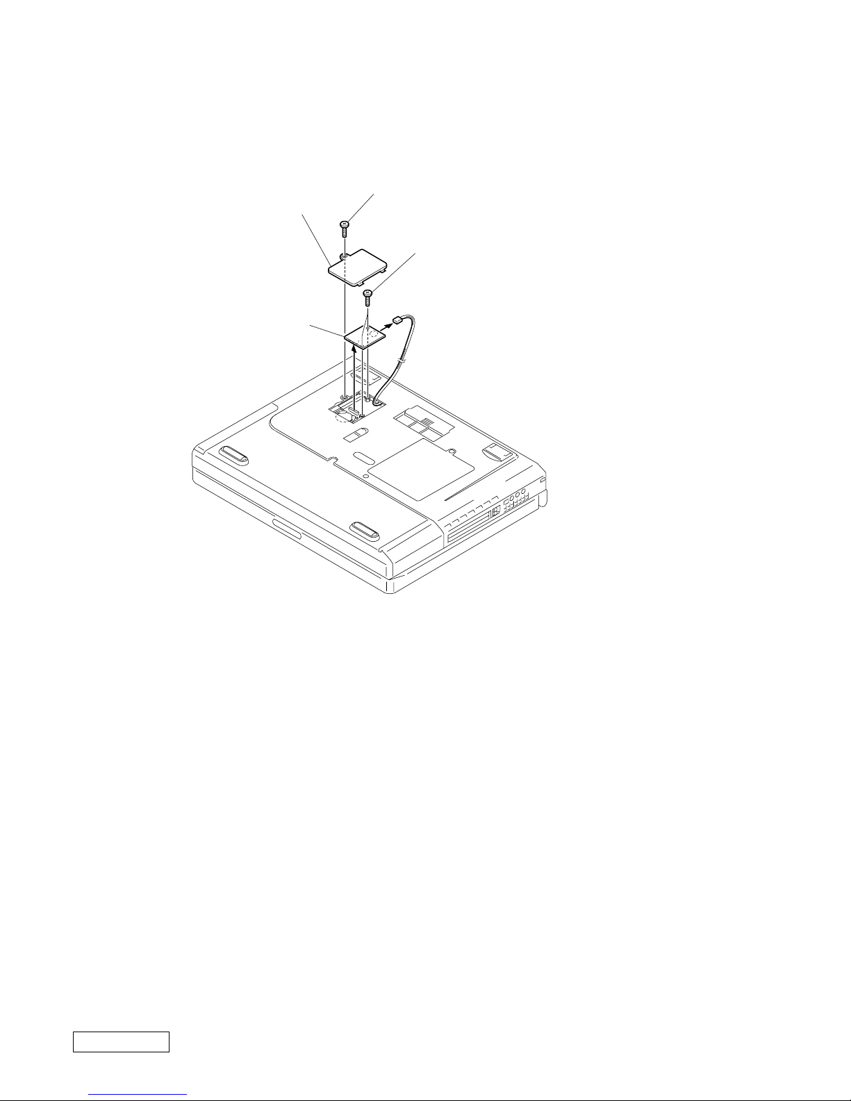
11. Card Modem (Removing from the bottom)
2Door Modem
4Card Modem
1Screw M2X4 Special Head (Black)
3Grip M2 (X2) (Black)
5
1-9
Confidential
PCG-FX777/FX877 (AM)
12. LCD Section (FX877 Model) – Made by TS –
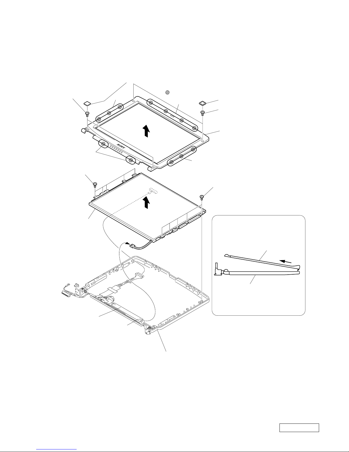
1. Assy Housing Bezel, LCD Unit
How to release the claw A.
Pull the Assy Housing Bezel
15SA-Z as shown to release
the claw A.
Assy Housing Bezel 15SA-Z
Assy Housing Display 15SA-Z
A
Order of releasing the claws C → B → A
Order of locking the claws A → B → C
Assy Housing Display 15SA-Z
: claw part
1Cover Screw Side (15) (X3)
5Cover Screw Lower
3Cover Screw
Shaft
3Cover Screw
Shaft
4+P 2.6X6
Lock Precision
Type3 (Black)
4+P 2.6X6 Lock
Precision Type3
(Black)
6Screw M2X4 Special
Head (Black)
1Cover Screw Side (15) (X3)
2+P M2X3 Lock (X3) (Gold)
2+P M2X3 Lock (X3) (Gold)
A
B
7
0
8
9
B
C
Assy Housing Bezel 15SA-Z
LCD unit
1-10
Confidential
PCG-FX777/FX877 (AM)
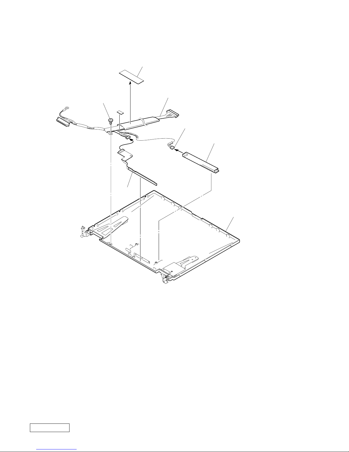
2. Inverter Unit, FPC, Assy Housing Display, Harness LCD
1
3
2Inverter Unit
9Assy Housing Display
15SA-Z
Inverter Unit
CN2
4FPC
7Screw M2X4
Special Head (Black)
8Harness LCD
5
6Filament Tape
1-11
Confidential
PCG-FX777/FX877 (AM)
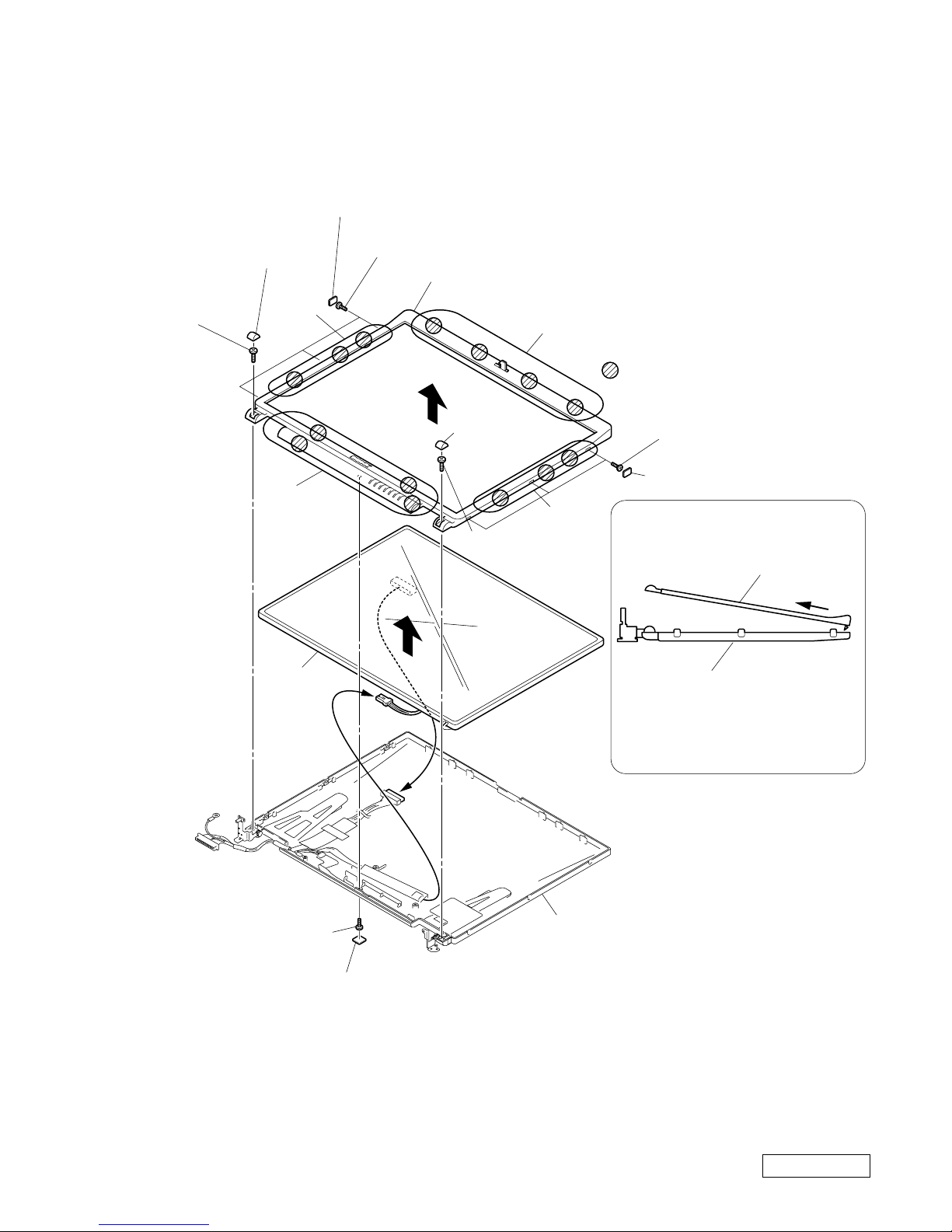
13. LCD Section (FX777 Model) – Made by HI–
1. Assy Housing Bezel (14 inch)
Order of releasing the claws c → b → a
Order of locking the claws a → b → c
How to release the claw a
5
a
Pull the Assy Housing Bezel
14H-Z as shown to release
the claw a.
: claw part
a
b
c
b
1Cover Screw Lower (X2)
1Cover Screw Upper (X2)
2Screw M2X4 Special
Head (X2) (Black)
2Screw M2X4 Special Head (X2)
(Black)
4Screw M2X4 Special Head (X5) (Black)
4Screw M2X4 Special
Head (X5) (Black)
6
7
3
Assy Housing Display 14SA-Z
Inverter Unit
Inverter Unit
CN2
Assy Housing Bezel 14H-Z
Assy Housing Display 14SA-Z
Assy Housing Bezel 14H-Z
LCD Unit
1-12
Confidential
PCG-FX777/FX877 (AM)
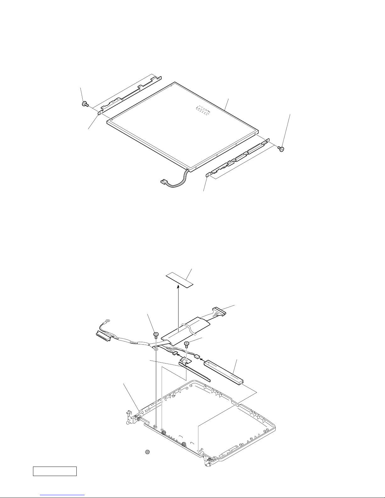
2. Bracket LCD Left, Bracket LCD Right, LCD Unit (14 inch)
3. FPC, Inverter Unit, Assy Housing Display, Harness LCD
5LCD Unit
2Bracket LCD Right 14 (SA)
4Bracket LCD
Left 14 (SA)
1ACE (M2) +B Lock
(X2) (Silver)
3ACE (M2) +B Lock
(X2) (Silver)
: claw part
5Screw M2X4 Special Head (Black)
6Screw M2X4 Special Head
(Black)
7Assy Housing Display
14SA-Z
4FPC
2Inverter Unit
3
1
0Harness LCD
8
9Filament Tape
1-13
Confidential
PCG-FX777/FX877 (AM)
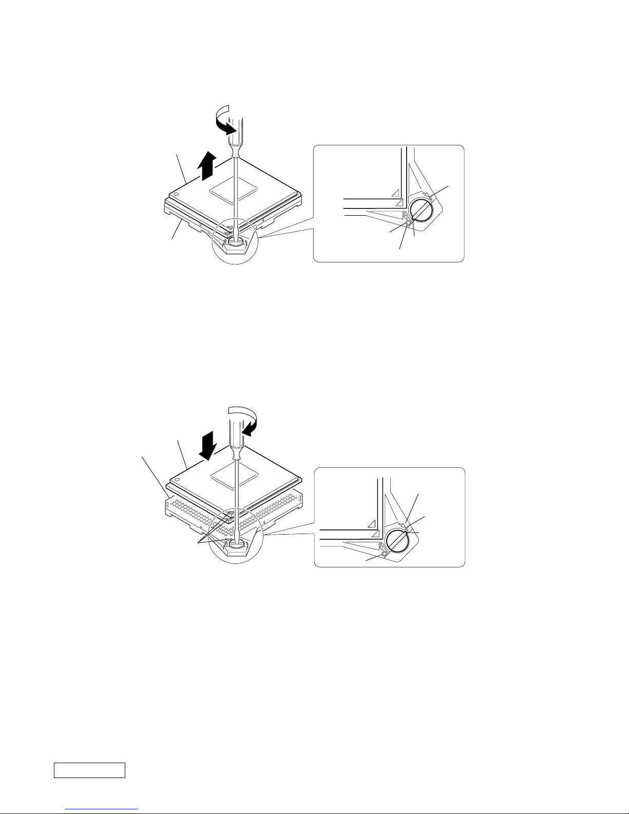
1-4.Replacing the CPU
NOTE:
This computer uses either one of the two types of CPU socket.
The CPU locking position and the lock-release position are different depending on the types of the CPU socket.
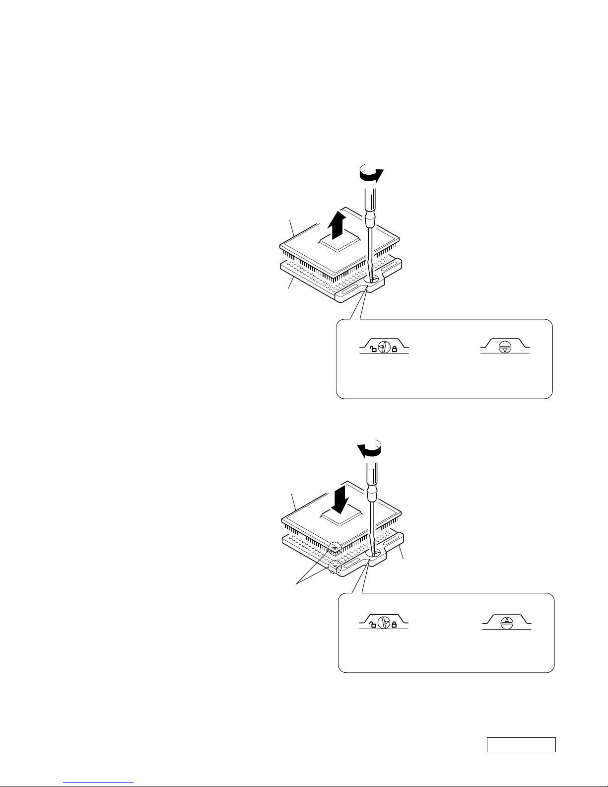
1. Socket type 1, 2
1. Removing the CPU
2. Installing the CPU
1 Align the triangle reference mark of
the CPU with that of the CPU socket
and insert all the pins of the CPU to
the corresponding holes of the CPU
socket.
2 Insert a flat-blade screwdriver into the
notch as shown in the illustration and
rotate it so that the protrusion comes
to the lock position.
1 Insert a flat-blade screwdriver into the
notch as shown in the illustration and
rotate it so that the protrusion comes
to the lock release position.
2 Pull the CPU gently upward to lift it
out of the CPU socket.
NOTE:
Rotate a flat-blade screwdriv er to the lock position securely . If not, the operation of the CPU may become unstable.
1
2
2
1
CPU socket
CPU
Lock release position
(made by HIROSE)
Lock release position
CPU socket
CPU
Lock position
(made by HIROSE)
Lock position
Reference
marks
1-14
Confidential
PCG-FX777/FX877 (AM)
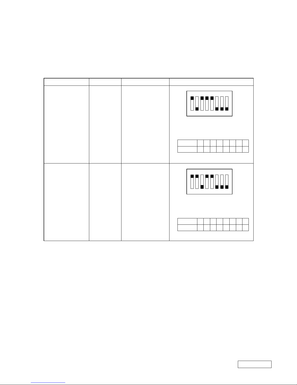
2. Socket type 3
1. Removing the CPU
2. Installing the CPU
1 Align the triangle r eference mark of the CPU with that of the CPU sock et and insert all the pins of the CPU to
the corresponding holes of the CPU socket.
2 Insert a flat-blade screwdriver into the notch as shown in the illustration and rotate it so that the protrusion
comes to the “L” (lock) position.
1 Insert a flat-blade screwdriver into the notch as shown in the illustration and rotate it so that the
protrusion comes to the “O” (lock release) position.
2 Pull the CPU gently upward to lift it out of the CPU socket.
NOTE:
• Considerable force is required to rotate a flat-blade screwdriver.
• Rotate a flat-blade screwdriver to the “L” (lock) position securely. If not, the operation of the CPU may
become unstable.
Lock release position [O]
2
1
CPU socket
CPU
1
2
Lock position [L]
CPU
CPU socket
Reference
marks
O
L
O
L
Protrusion
Protrusion
1-15
Confidential
PCG-FX777/FX877 (AM)
(END)
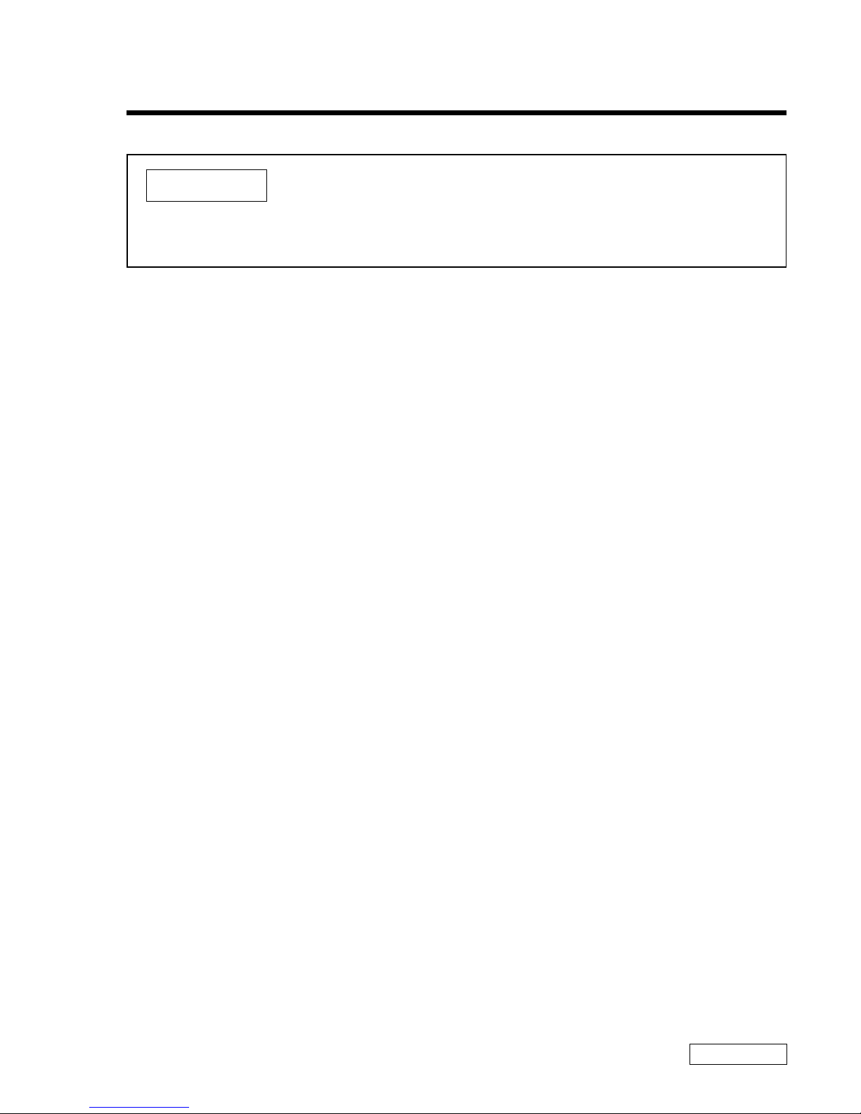
1-5. DIP Switch Setting of the MBX-49 Board
Set the DIP switch on the MBX-49 board (main board) to match with the LCD that is used in this computer, because
several types of LCD are used as shown in the following table and the DIP switch setting differs depending
on the LCD type.
MODEL
FX877
FX777
Name of LCD
TS
HI
Part No.
A-8058-271-A
A-8025-245-A
DIP switch setting
The upper position where ON indication is
shown is the ON position . The lower
position is the OFF position.
The upper position where ON indication is
shown is the ON position . The lower
position is the OFF position.
12345678
01000111
0 : ON 1: OFF
No.
ON/OFF
12345678
00100111
0 : ON 1: OFF
No.
ON/OFF
1234567
8
O
N
1234567
8
O
N

MEMO
2-1
Confidential
PCG-FX777/FX877 (AM)
CHAPTER 2.
SELF DIAGNOSTICS
Please confirm “Self Diagnostics” method which will be informed you with distribution
of “Self Diagnostics” software.
ATTENTION
(END)

MEMO
Confidential
PCG-FX777/FX877 (AM)
(END)
3-23-1
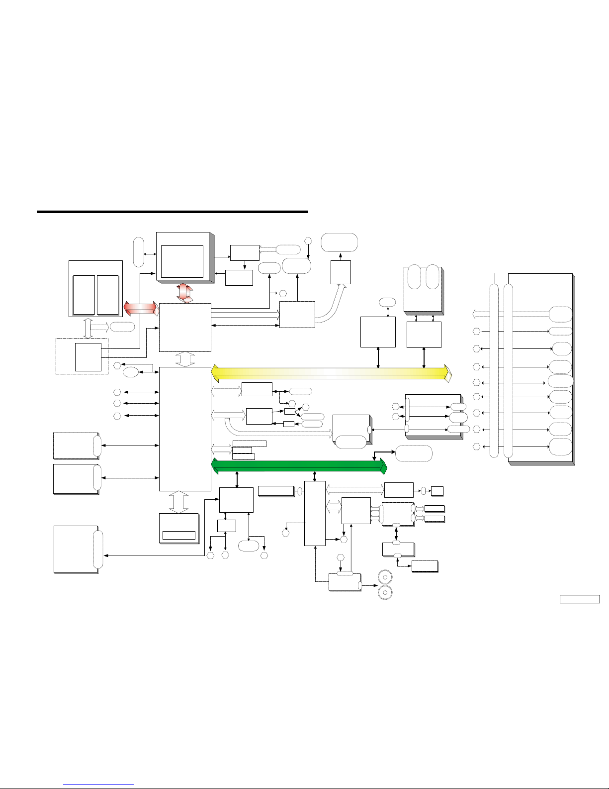
CHAPTER 3.
BLOCK DIAGRAM
Port Replicator
CNX-125
(Touchpad BTN)
CNX-123
MODEM
MDC Module
µ-PGA2 Connector
CPU
MP III 1000/900 MHz
(Cache:256kB OD)
Memory Subsystem
PC100 SO-DIMM
SO-DIMM
Socket 2
Row# 2,3
SO-DIMM
Socket 1
Row# 0,1
P C I Bus
FW82801
VID
Selector
CPU
Volt Reg
CLK
GEN
IMI
C9835
SMBUS2
USB
PORT 0
Primary IDE
Secondary IDE
i.Link
TI
TSB43AA22PD
T
Audio
AD1881A
AC Link
Ext. MIC
Headphone
Am
p
Am
p
Ether PHY
82562ET
Cardbus
RICOH
R5C476 II
L P C
Super I/O
SMSC
LPC47N227
FDD
RS232C
Buffer
Serial
Dsub-9
Parallel
Dsub-25
MDC CN
BtoB(40pin)
EC/KBC/
SPIC
HITACHI
H8S/2149
SMBUS0
I/O Expander
/SMBUS MUX
O2micro
OZ998
TV
Encoder
CH7007A
TV-OUT
mini Jack
VGA
DSub-15
LCD
50pin CN
(LED Signal Include)
ITP Connector
Master IDE Device
Optical Devices
FPC(50pin)
Multi Purpose Bay
(FDD/2ndBattery)
SMBUS2
DVO
DVO
AHA
ATF Sense
FAN control
ADM1030
FWH
Flash BIOS ROM
AHA
viaLPC
Int. Keyboard
CN
FAN
Batter1
FW82801
HDD
BtoB CN
(50pin)
USB PORT3
LCI
SO-DIMM
Batter2
Refer to Clock Generator Block
Diagram
FW82801
SMBUS2
GMBUS
Debug Board
CN
BtoB (30pin)
VDC_IN
PCG-FX Series
BLOCK DIAGRAM Rev. 1.00
w/ Port Replicator (PCGA-PRFX1) 10/10/00
Serial
DSUB-9
Parallel
DSUB-25
USB
PORT2
VGA
4
2
3
5
1
CNX-126
DC-IN
USB
PORT3
7
100-pin Port Replicator CONNECTOR
100-pin Port Replicator CONNECTOR
RJ-45
ETHER
1
2 3
5
7
RJ-11
USB
Port 1
6
6
CN
USB PORT1
USB PORT2
i.Link
4-pin
PWS-13
(Battery CONN & Lid-
SW)
CN
CNCN
SWX-73
(PPK&SPKR C N )
CN
FW82807
Bay CN (50pin)
PC Card
Slot x2
PC Card
Socket 1
PC Card
Socket 2
FW82815
CN
CN
Stereo
Speaker
LVDS
CN
SMBUS1
9
8
8
RJ-45
4
USB
PORT0
9
10
10
CN
11
LED
PPK
Power BTN
11
CN
CN
CN
Touch pad
12
PS/2
MiniDIN-6
for KBD
12
PS/2
CLK GEN
EEPROM
for Password

MEMO
Confidential
PCG-FX777/FX877 (AM)
(END)
4-24-1
CHAPTER 4.
FRAME HARNESS DIAGRAM
KEY BOARD
DC FAN
CPU
VIDEO OUT
EXTERNAL MICROPHONE
HEADPHONE
IEEE 1394 i.LINK
CN2801
CN1101
CN701
CN802
CN1701
CN1703
CN1301
CN1
CN502
1
250
49
Side
PC CARD
CONNECTOR
RAM
RAM
BATTERY PACK
PWS-13 Board
(Side-B)
CNX-125 Board
(Side-A)
TOUCH PAD
COMBINATION
DVD-ROM
DRIVE
FLOPPY DISK
DRIVE
2nd BATTERY PACK
(OPTION)
SWX-73
(Side-A)
MODEM CARD
MBX-49 Board
(Side-A)
J1
Speaker L Speaker R
CNX-123 Board
(Side-A)
Rear Panel
PHONEPRINTER SERIAL USB
NETWORK
MONITORDC-IN USB
LCD
INVERTER
HARD DISK
FFC LED
1
122
143
144
1
2
1
2
1
1
1
6
6
1
2
59
60
1
2
59
60
143
144
CN102
CN501
CN2701
CN4005
CN1202
1
75
150
76
FPC
FPC
CN2301
CN2302
CN4001
CN4002
49
50
50
CN4004
11112 8
8
CN1502
CN702
CN1801
CN3001
CN1902
CN1401
CN2201
CN2004 CN2602
CN1802
1
1
1
1
11
1
25
2
2
2
30
29
50
49
10
8
99
100
18
CN1602
1
2
29
30
1
1
1
110
2
2
22930
CN301
CN303
CN302
CN101
1
1
18
CN105
CN103
CN152
CN151
2
1
20
CN5002 CN5001
OPTION
PC100 SO-DIMM
(FX877 Model)
256MB
(FX777 Model)
128MB
From board to connector (direct connection)
Harness (connector at both end)
Harness (soldered at one end)
Connectors soldered on board and appearing on the panel

MEMO
5-1
CHAPTER 5.
EXPLODED VIEWS AND PARTS LIST
NOTE:
• The mechanical parts with no reference number in the
exploded views are not supplied.
• Items marked “ * ” are not stoc ked since they are seldom
required for routine service. Some delay should be
anticipated when ordering these items.
• When two or more parts are shown in parallel, use the
part described first as the main part.
The components identified by mark 0 or
dotted line with mark 0 are critical for safety .
Replace only with part number specified.
Les composants identifiés par une marque
0 sont critiques pour la sécurité.
Ne les remplacer que par une pièce portant
le numéro spécifié.
Confidential
PCG-FX777/FX877 (AM)
How to use properly the repair parts.
There are some parts that use the 2 types ; the [CH] parts or alternately the [JP] parts, in this series.
Use the [CH] repair parts for the [CH] type product, vice versa.
The jack and connectors mounted on the board of this model can be repaired in the [JP] type only.
And regarding the boards of [CH] type, the discrete parts on the boards cannot be replaced.
However, some connectors can be replaced.
For details, refer to “5-5.Connector Section”.
[ How to identify the parts ]
[ Repair part description example ]
Ref.No. Part No. Description
999 A-8058-171-A [CH]...MBX-49 Z3 (CH) ASSY (S)
999 A-8025-236-A [JP]...MBX-49 Z3 (JP) ASSY (S)
A-xxx-xxx-A x xxxxxxxxx
2 : Using [JP] type
6 : Using [CH] type
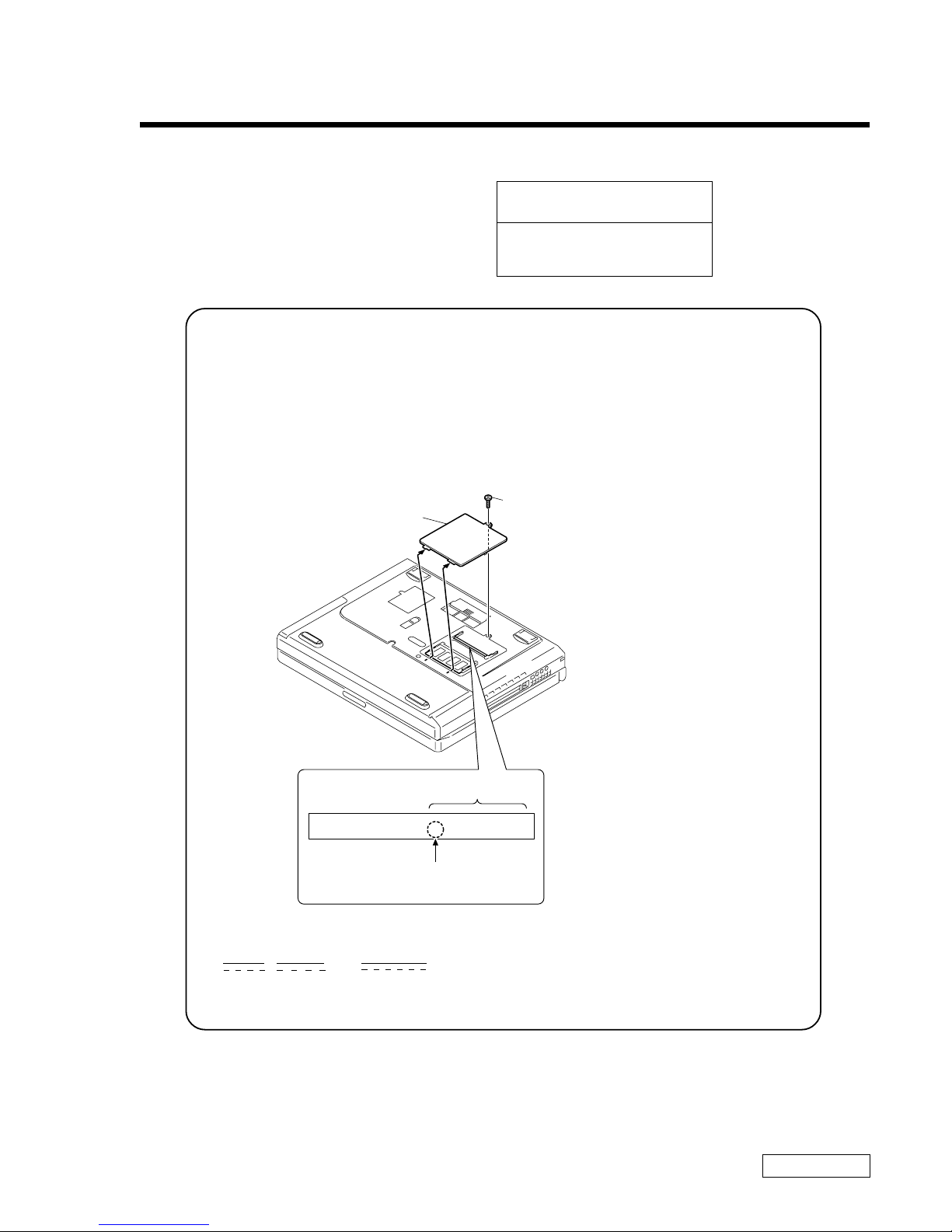
Identfication Seal
Serial No.
2Door DIMM
1M2X4
Special Head (Black)
Identification seal is attached on the
expansion memory connector.
5-2
Confidential
PCG-FX777/FX877 (AM)
Ref.No. Part No. Description Ref.No. Part No. Description
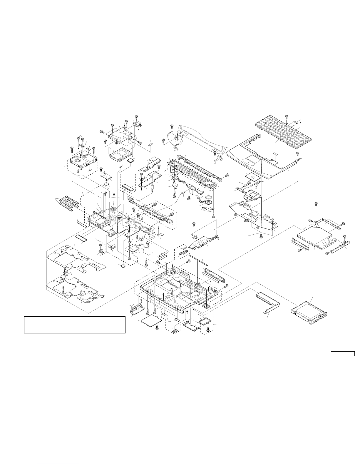
5-1. Main Section
1 X-4623-988-1 [CH]...ASSY BOTTOM (AK)
1 X-4623-762-3 [JP]...ASSY BOTTOM (AS)
3 4-640-837-32 DOOR BATTERY
3 4-640-837-22 DOOR BATTERY
* 8 4-651-706-21 HEATSINK BOTTOM
* 8 4-651-706-01 HEATSINK BOTTOM
* 11 4-651-707-11 INSULATOR HEATSINK BOTTOM
* 11 4-651-707-21 INSULATOR HEATSINK BOTTOM
12 1-763-658-11 FAN, DC (WITH HEAT SINK)
15 4-643-832-31 DUMMY CARD
15 4-643-832-21 DUMMY CARD
18 A-8025-266-A [CH]...SWX-73 (CH) ASSY (S)
18 A-8066-960-A [JP]...COMPLETE PWB SWX-73Z3
19 X-4623-388-2 ASSY HOOD KEYBOARD (Z)
20 1-529-287-11 SPEAKER UNIT
21 3-718-233-01 NUT, PLATE
22 1-790-639-22 FPC 50PIN (FOR HDD)
24 A-8066-903-A (FX877)...ASSY HDD 20GB (H, 15F) (S)
24 A-8058-224-A (FX777)...ASSY HDD 15GB (T, 15B) (S)
25 1-476-648-71 KEY BOARD UNIT (LA)
26 X-4623-390-1 ASSY PALMREST
27 1-772-529-72 PAD, TOUCH
28 A-8025-267-A [CH]...CNX-125 (CH) ASSY (S)
28 A-8066-959-A [JP]...COMPLETE PWB CNX-125Z3
29 4-651-699-01 BRACKET PAD
* 30 4-651-708-02 BRACKET (HDD)
31 4-640-861-04 BRACKET CD-ROM R
32 1-796-072-21 COMBO DRIVE (UJDA710)
33 X-4623-436-2 ASSY DOOR DVD-RW PA
34 4-640-860-03 BRACKET (CD-ROM L)
38 4-651-713-11 [CH]...DOOR (IO) (
∗1
)
38 4-651-713-02 [JP]...DOOR I/O (
∗1
)
39 4-651-844-01 FOOT REAR
40 4-651-714-01 DOOR DOCKING CONNECTOR
41 4-640-851-11 FOOT FRONT
46 A-8025-233-A [CH]...PWS-13 (CH) ASSY (S)
46 A-8066-958-A [JP]...COMPLETE PWB PWS-13Z3
48 1-761-380-23 CARD, MODEM
52 1-790-640-11 FPC 50PIN (FOR CD-ROM)
55 4-640-845-11 BUTTON BAY
56 4-644-349-01 LATCH BAY
* 57 4-640-854-01 SPRING BAY
* 58 4-651-850-01 BRACKET BOTTOM
* 59 4-640-857-01 DOOR BATTERY SPRING
60 4-651-698-01 DISPLAY BASE
63 4-651-928-02 COVER BATTERY CONNECTOR
67 4-652-099-21 [CH]...LABEL I/O (
∗1
)
67 4-652-099-02 [JP]...LABEL I/O (
∗1
)
* 71 4-641-851-02 SPRING (FDD), PLATE
* 72 4-651-709-41 [CH]...BRACKET IO
* 72 4-651-709-01 [JP]...BRACKET IO
74 4-651-702-01 DOOR DIMM
* 76 4-644-361-01 BRACKET SPK
* 78 4-644-362-21 PLATE PALMREST
* 78 4-644-362-11 PLATE PALMREST
81 6-600-065-01 (FX877)...IC MT8LSDT3264HG-10EB1
(PC-100 SO-DIMM (256MB))
81 8-749-019-00 (FX777)...IC HYM71V16M655AT6-P
(PC-100 SO-DIMM (128MB CL2))
81 6-600-041-01 (FX777)...IC HYM71V16M655HCT6-P
(PC-100 SO-DIMM (128MB CL2))
84 1-960-827-21 HARNESS (2 PIN)
88 A-8058-171-A [CH]...MBX-49Z3 (CH) ASSY (S)
88 A-8058-172-A [JP]...MBX-49Z3 (JP) ASSY (S)
105 4-641-630-11 COVER BAY HOLE
123 1-790-711-21 FFC (PPK)
124 1-757-767-11 FFC (TP-CNX)
125 1-790-710-11 FFC (SWX-PWS)
* 128 4-653-452-01 PLATE, GROUND
* 134 4-645-433-01 BRACKET BAY CONNECTOR
136 4-644-357-01 CUSHION SPK
147 8-759-835-93 (FX877)...
IC KP80526GY001256 (PIII 1000 MHz)
147 6-700-454-01 (FX777)...
IC KP80526GY900256 (PIII 900 MHz)
148 X-4623-561-2 ASSY LATCH DETECTOR
* 152 4-651-871-01 HEAT SINK
153 4-652-012-01 SHEET, ELECTRIC HEAT
154 4-651-989-01 SPACER (MBX)
155 4-651-701-01 DOOR MODEM
156 4-653-151-01 SPACER (KBF)
157 4-653-466-01 CUSHION (HD-M)
159 4-653-963-01 SHIELD (CNX)
160 4-653-964-01 SPACER (B/P)
161 4-654-019-01 GASKET (AV)
162 4-654-047-01 SHIELD (AV)
163 4-653-936-01 GASKET (HB/M)
164 1-779-745-21 [JP]...JACK, DC
165 1-815-422-11 [JP]...USB CONNECTOR (VERTICAL)
166 1-695-514-21 [JP]...JACK (SMALL TYPE) 1P
167 1-815-221-21 [JP]...CONNECTOR, USB (VERTICAL)
168 1-793-430-11 [JP]...JACK, SMALL TYPE
169 4-653-962-01 SHIELD (USB)
170 4-644-667-11 COVER RJ-11
170 4-644-667-01 COVER RJ-11
171 4-654-350-01 SHEET (CPU), THERMAL
184 4-654-776-01 INSULATOR (SCREW)
185 4-658-542-01 SPACER (KEY BOARD)
186 4-654-320-21 SHEET (COIL), THERMAL
800 Refer to section “5-2. FDD Section”.
B1 4-641-726-41 SCREW (M2), SPECIAL HEAD
B3 4-644-899-01 SCREW (M2), 0 NUMBER P3 KIND
B4 4-639-112-01 SCREW M2X4
B7 4-644-402-12 SCREW (MBX)
B10 4-652-498-01 +B M2 (NOJI)
B12 4-645-177-01 SCREW (M1.7X3.5)
B14 4-645-497-01 SCREW (M2.6), CROSS (HOLE) BIND
B15 4-635-301-01 SCREW M3X4
B18 4-635-966-01 SCREW (HEX)
B31 4-645-214-11 GRIP, M2
B32 7-621-772-68 SCREW +B 2X12
B33 4-642-852-21 +B M2
B34 4-641-726-11 SCREW (M2), SPECIAL HEAD
B35 7-621-772-70 SCREW +B 2X14
B36 7-622-205-05 NUT (M2 TYPE2), HEXAGON
B40 4-641-726-11 [JP]...SCREW (M2), SPECIAL HEAD
B40 4-641-726-41 [CH]...SCREW (M2), SPECIAL HEAD
∗1 : When replacing the part Ref No.38 or Ref No.67, replace them together.
In addition, select the same type of the parts ([CH] type or [JP] type) as that of the original model
from which you remove the defective part.
Confidential
PCG-FX777/FX877 (AM)5-3 5-4
H
27
28
124
125
701 (Refer to Page 5-10.)
800 (Refer to Page 5-5.)
B3
163
160
161
159
167
(∗3)
162
C
B34
B3
B3
34
B34
B18
B18
B34
78
24
B15
B15
46
81
E
E
F
G
F
I
D
C
I
J
H
A
B
B
A
K
K
L
L
D
52
72
166
(∗3)
B4
B4
B1
B32
B34
B4
76
76
20
123
20
18
19
21
60
38
(∗1)
67
(∗1)
40
3
59
74
58
26
25
29
81
B1
B1
B34
B34
22
B1
B7
B34
B14
B14
B14
B34
136
136
11
8
134
63
71
32
31
B10
B10
B10
33
B12
B12
J
30
147
B34
48
84
148
FX370/
FX390
Model Only
1
N
B1
B1
B1
88
152
153
B34
B34
157
154
B31
B36
B40
(∗4)
165
(∗3)
169
164
(∗3)
N
55
155
B34
105
39
57
56
not
supplied (∗2)
170
B1
184
171
G
12
B3
156
128
B33
B3
168
(∗3)
185
185
186
41
15
∗2 Use the Sony lithium battery CR2025 or its compatible
that is available on market, for the backup battery.
∗3 [JP] type only.
∗4 Use the different types depending on [CH] or [JP] of this model.
∗1: When replacing the part Ref No.38 or Ref No.67, replace them together.
In addition, select the same type of the parts ([CH] type or [JP] type) as
that of the original model from which you remove the defective part.
Confidential
PCG-FX777/FX877 (AM)
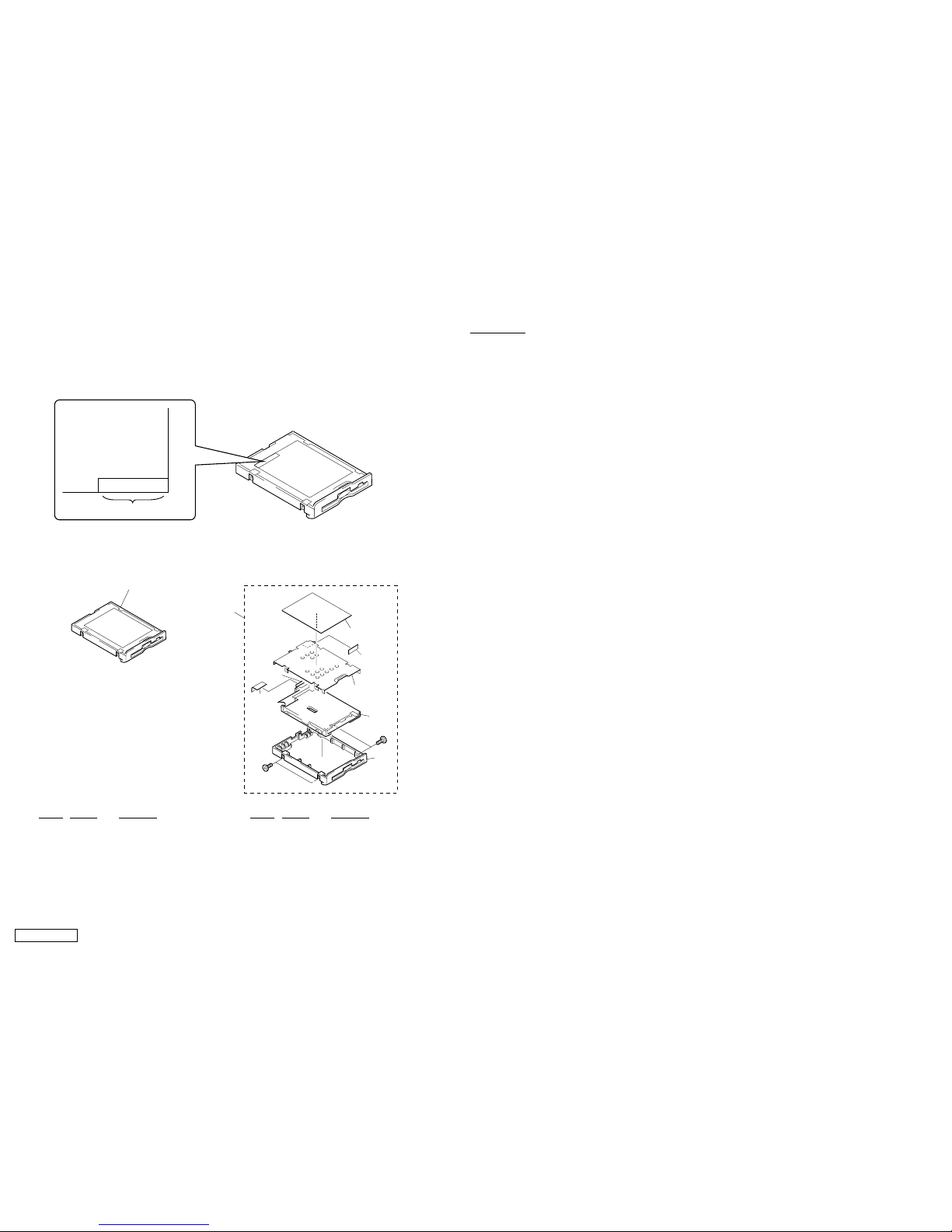
5-2. FDD Section
How to use properly the FDD repair parts.
Types of service to be provided are different depending on the serial No. of the FDD in use.
The service types are shown below depending on the serial No. that is printed in the bottom right of the FD label.
[Serial No. : 4-656-805-0*] [Serial No. : 4-641-763-3*]
800
803
802
B1
B1
801
805
804
807
806
800
Ref.No. Part No. Description
800 A-8025-674-A FDD UNIT ASSY (TN-CH)
Ref.No. Part No. Description
800 A-8025-669-A ASSY BAY FD (TN)
801 4-640-828-01 PLATE FDD
802 1-796-231-11 FDD (FD-07-7760)
803 X-4623-835-1 ASSY BOTTOM FDD Z (TCY3)
804 1-790-641-11 FPC 50PIN (FOR FDD)
805 4-641-629-01 INSULATOR FDD
806 4-641-763-31 LABEL FD
807 4-644-053-01 SPACER FDD
B1 4-646-807-01 0 PLATE M2.5 (FDD)
Serial No.
X-XXX-XXX-XX
Label FD
5-5 5-6
MEMO
 Loading...