

Sony VAIO PCG-F610, VAIO PCG-F630 Service Manual
PCG-F610/F630
SERVICE MANUAL
Ver 5-2002A
Revision History
Illust : PCG-F630
US Model
Canadian Model
S400
Confidential
9-872-145-15
NOTEBOOK COMPUTER
Information in this document is subject to change without notice.
Sony and VAIO are trademarks of Sony . Intel logo and Intel Inside
logo are registered trademarks of Intel Corporation. Pentium MMX
is a trademark of Intel Corporation. Microsoft, MS-DOS, W indows,
the W indows 95 and W indows 98 log o are trademarks of Microsoft
Corporation.
All other trademarks are trademarks or registered trademarks of
their respective owners. Other tr ademarks and trade names may be
used in this document to refer to the entitles claiming the marks and
names or their produces. Sony Corporation disclaims any proprietary
interest in trademarks and trade names other than its own.
Caution Markings for Lithium/Ion Battery - The following or similar
texts shall be provided on battery pack of equipment or in both the
operating and the service instructions.
CAUTION: Danger of explosion if battery is incorrectly replaced.
Replace only with the same or equivalent type recommended by
the manufacturer. Discard used batteries according to the
manufacturer’s instructions.
CAUTION: The battery pack used in this de vice may present a f ire
or chemical burn hazard if mistreated. Do not disassemble, heat
above 100°C (212°F) or incinerate.
Dispose of used battery promptly.
Keep away from children.
CAUTION: Changing the back up battery.
• Overcharging, short circuiting, reverse charging, multilation or
incineration of the cells must be avoided to prev ent one or more of
the following occurrences; release of toxic materials, release of
hydrogen and/or oxygen gas, rise in surface temperature.
• If a cell has leaked or vented, it should be replaced immediately
while avoiding to touch it without any protection.
Service and Inspection Precautions
1. Obey precautionary markings and instructions
Labels and stamps on the cabinet, chassis, and components identify areas
requiring special precautions. Be sure to observe these precautions, as well
as all precautions listed in the operating manual and other associated
documents.
2. Use designated parts only
The set’s components possess important safety characteristics, such as
noncombustibility and the ability to tolerate large voltages. Be sure that
replacement parts possess the same safety characteristics as the originals.
Also remember that the 0 mark, which appears in circuit diagrams and
parts lists, denotes components that have particularly important safety
functions; be extra sure to use only the designated components.
3. Always follow the original design when mounting
parts and routing wires
The original layout includes various safety features, such as inclusion of
insulating materials (tubes and tape) and the mounting of parts above the
printer board. In addition, internal wiring has been routed and clamped so
as to keep it away from hot or high-voltage parts. When mounting parts or
routing wires, therefore, be sure to duplicate the original layout.
4. Inspect after completing service
After servicing, inspect to make sure that all screws, components, and wiring
have been returned to their original condition. Also check the area around
the repair location to ensure that repair work has caused no damage, and
confirm safety.
5. When replacing chip components...
Never reuse components. Also remember that the negati ve side of tantalum
capacitors is easily damaged by heat.
6. When handling flexible print boards...
•The temperature of the soldering-iron tip should be about 270C.
•Do not apply the tip more than three times to the same pattern.
•Handle patterns with care; never apply force.
Caution: Remember that hard disk drives are easily damaged by
vibration. Always handle with care.
ATTENTION AU COMPOSANT AYANT RAPPORT
À LA SÉCURITÉ!
LES COMPOSANTS IDENTIFÉS P AR UNE MARQUE 0 SUR LES
DIAGRAMMES SCHÉMA TIQUES ET LA LISTE DES PIÈCES SONT
CRITIQUES POUR LA SÉCURITÉ DE FONCTIONNEMENT. NE
REMPLACER CES COMPOSANTS QUE PAR DES PIÈSES SONY
DONT LES NUMÉROS SONT DONNÉS DANS CE MANUEL OU
DANS LES SUPPÉMENTS PUBLIÉS PAR SONY.
Confidential
PCG-F610/F630 (UC)
— 2 —

TABLE OF CONTENTS
Section Title Page
CHAPTER 1. REMOVAL
1-1. Flowchart ......................................................................... 1-1
1-2. Main Electrical Parts Location Diagram ......................... 1-1
1-3. Removal ........................................................................... 1-2
1. Hinge Cover ..................................................................... 1-2
2. Keyboard Unit, Palm Rest Assy, Hood Keyboard Assy
Touch Pad, CNX-100 Board ............................................ 1-2
3. Display Assy, CD-ROM Drive, DVD-ROM Drive.......... 1-3
4. HDD Assy, Cooling Unit ................................................. 1-3
5. SWX-57 Board, Latch Detector Unit, PWS-9 Board ...... 1-4
6. Modem Unit, MBX-39 Board.......................................... 1-4
7. Speaker Unit, SWX-56 Board ......................................... 1-5
8. SO-DIMM........................................................................ 1-5
9. LCD Section (F630 Model) – Made by SA – .................. 1-6
1. Bezel Housing Assy..................................................... 1-6
2. LCD Harness, Bracket LCD Left, Bracket LCD Right,
LCD unit (13inch) ....................................................... 1-7
3. FPC, Inverter Assy, Display Housing Assy.................. 1-7
10.LCD Section (F610 Model) – Made by SA –.................. 1-8
1. Bezel Housing Assy..................................................... 1-8
2. LCD Harness, Bracket LCD Left, Bracket LCD Right,
Hinge Left, Hinge Right, LCD unit (12inch)............... 1-9
3. FPC, Inverter Assy, Display Housing Assy.................. 1-9
1-4. Replacing the CPU ........................................................ 1-10
1. Removing the CPU ........................................................ 1-10
2. Installing the CPU.......................................................... 1-10
1-5. Replacing Various Connectors on the MBX-39 Board.. 1-11
1. Removing the I/O Bracket ............................................. 1-11
2. Removing the Various Connectors ................................. 1-11
1-6. Using Common Flexible Boards and
Dedicated Flexible Boards Differently As Specified *.. 1-12
(to 1-15)
Section Title Page
CHAPTER 2. SELF DIAGNOSTICS
2-1. Required Tools and Peripheral Devices........................... 2-1
2-2. Tools and Peripheral Device Connection.........................2-3
2-3. Starting up the Service Diagnostics ................................. 2-4
2-4. Outline of Service Diagnostics Functions ....................... 2-4
2-5. Inspecting W indows.........................................................2-7
(to 2-7)
CHAPTER 3. BLOCK DIAGRAM............................... 3-1
(to 3-2)
CHAPTER 4. FRAME HARNESS DIAGRAM........ 4-1
(to 4-2)
CHAPTER 5. EXPLODED VIEWS AND
PARTS LIST............................................5-1
5-1. Main Section .................................................................... 5-2
5-2. LCD Section (F630 Model) – Made by SA –................. 5-5
5-3. LCD Section (F610 Model) – Made by SA –.................. 5-7
5-4. Connector Section............................................................ 5-9
(to 5-10)
∗ Be sure to read section “1-6. Using Common Flexible Boards
and Dedicated Flexible Boards Differently AS Specified”
• Abbreviations
UC : US model / Canadian model
History of the changes is shown as the
“Revision History” at the end of this data.
— 3 —
Confidential
PCG-F610/F630 (UC)
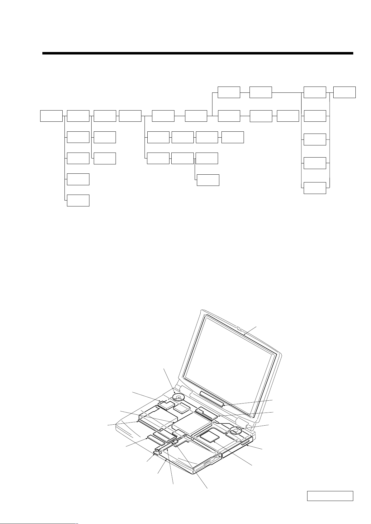
1-1. Flowchart
CHAPTER 1.
REMOVAL
POWER
OFF
HOOD
KEYBOARD
ASSY
SO-DIMM
BATTERY
PACK
FDD
HINGE
COVER
P 1-2
KEYBOARD
UNIT
P 1-2P 1-2
SPEAKER
UNIT
P 1-5P 1-5
SWX-56
BOARD
P 1-5
P ALM REST
ASSY
P 1-2 P 1-3
HDD
P 1-3
P ALM REST
PLA TE
CD-ROM/
DVD-ROM
DRIVE
PWS-9
BOARD
P 1-4
BRACKET
PAT
P 1-2 P 1-2P 1-2
DISPLAY
ASSY
P 1-3
DETECTOR
CNX-100
LA TCH
P 1-4
TOUCH
PAD
BOARD
P 1-2
BEZEL
HOUSING
ASSY
∗
P 1-6
(P1-8)
COOLING
UNIT
P 1-3
SWX-57
BOARD
P 1-4
LCD
UNIT
∗ P 1-7
(P1-9)
MODEM
UNIT
P 1-4
5, 9through 0
• P XX means pages that appears in this manual.
• Remember that hard disk drives are easily damaged by vibration. Always handle with care.
INVERTER
ASSY
∗ P 1-7
(P1-9)
MBX-39
BOARD
P 1-4
∗ : F630 Model (Made by SA)
( ) : F610 Model (Made by SA)
LCD
HARNESS
∗
P 1-7
(P1-9)
FPC
∗ P 1-7
(P1-9)
BRACKET
LCD LEFT
∗ P 1-7
(P1-9)
BRACKET
LCD RIGHT
∗ P 1-7
(P1-9)
DISPLAY
HOUSING
ASSY
∗ P 1-7
(P1-9)
1-2. Main Electrical Parts Location Diagram
LCD Unit
Speaker Unit
Cooling Unit
HDD
MBX-39 Board
CNX-100 Board
SWX-57 Board
FD Drive
CD-ROM Drive
DVD ROM Drive
Modem Unit
Inverter Unit
SWX-56 Board
Speaker Unit
or
PWS-9 Board
Touch Pad
1-1
Confidential
PCG-F610/F630 (UC)
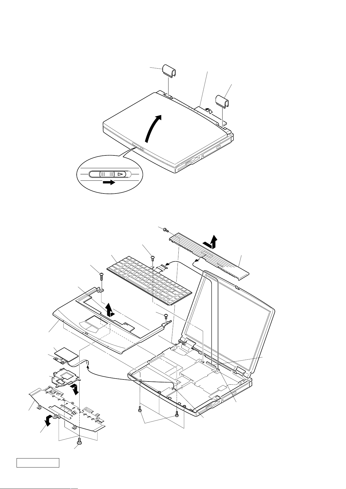
1-3.Removal
1. Hinge Cover
2Hinge Cover
4
3
1Door I/O
2Hinge Cover
2. Keyboard Unit, Palm Rest Assy, Hood Keyboard Assy, Touch Pad, CNX-100 Board
1M2X4 Special Head
3M2X4 Special Head
Keyboard Unit
4
6+B 2X18
2Pull it up sliding it
to the right.
Hood Keyboard Assy
7Pull it to the front slightly
and raise to remove it.
Palm Rest Assy
Touch Pad
CNX-100
Board
Bracket Pat
Palm Rest
Plate
9Remove by
pulling slightly
to the front
8M2X4 Special Head (x4)
0Remove by
pressing to
the rear
5Screw (M2),
0 Number P3 Kind (X4)
6M2X4
Special Head
MBX-39 Board
CON16
MBX-39 Board
CON22
PWS-9 Board
BCN2
Confidential
PCG-F610/F630 (UC)
1-2
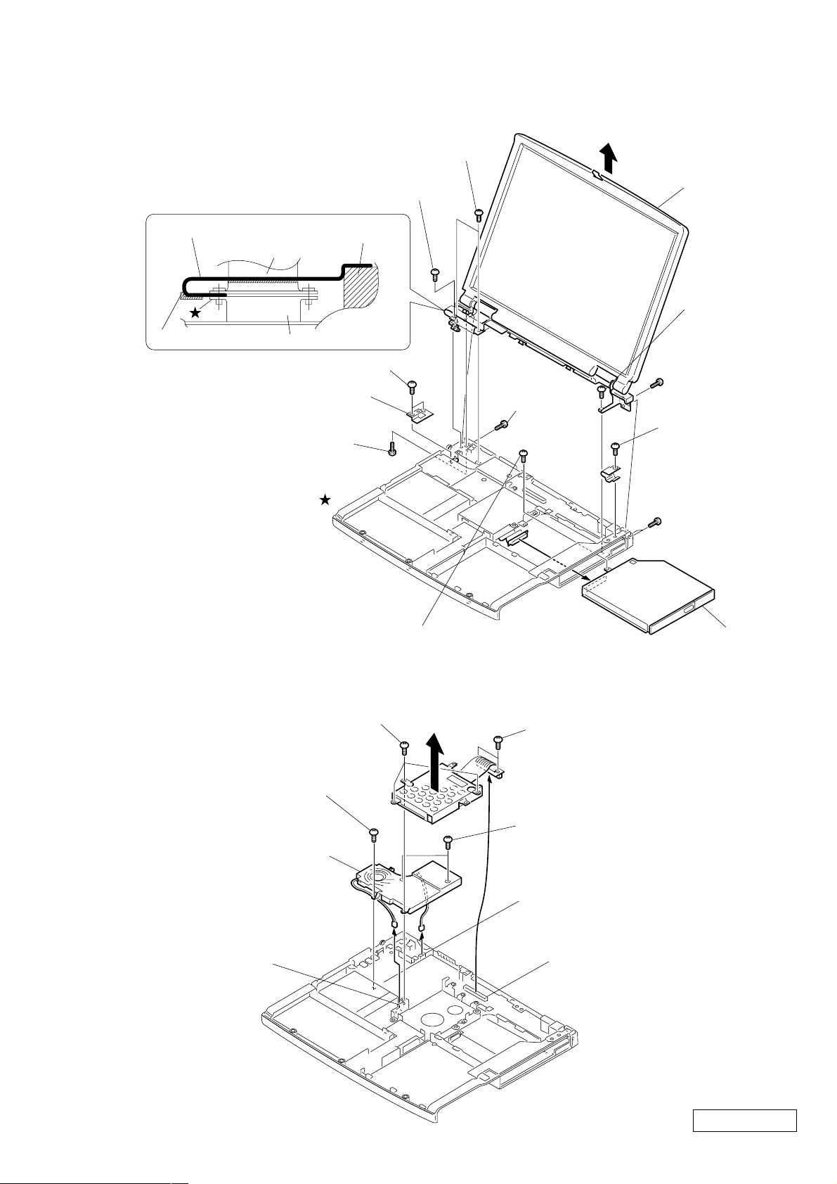
3. Display Assy, CD-ROM Drive, DVD-ROM Drive
∗1
9M2X6 Special Head
Shield Tape (FPC)
Cooling unit
FPC
Hinge Left
MBX-39 Board CON4
5M2X4 Special Head (X2)
6GND Plate Hinge
1Screw (M2),
0 Number P3 Kind
∗1
The FPC is fixed to the shield tape (FPC)
on the connector (CON4) (star marked )
on the MBX-39 board by a screw.
The shield tape (FPC) fixed by the scre w is
bent on the Hinge Left and it is attached to
the Hinge Left, FPC and cooling unit.
8M2X6 Special Head
(X2)
7M2.6 Cross
(Hole) Bind
4
q;
Display Assy
9M2X6 Special
Head
7 M2.6 Cross (Hole)
Bind (X2)
2Bolt (M2X2)
Spring
7M2.6 Cross (Hole)
Bind (X2)
4. HDD Assy, Cooling Unit
3M2X4 Special Head (X3)
6M2X6 Special Head
7Cooling Unit
MBX-39 Board
CON15
3M2X4 Special Head
4HDD Assy
2FPC 50 Pin (for HDD)
5
CD-ROM Drive or
DVD-ROM Drive
1M2X4 Special Head
(X2)
6M2X8 Special Head (X2)
MBX-39 Board
CON17
MBX-39 Board
CON10
1-3
Confidential
PCG-F610/F630 (UC)
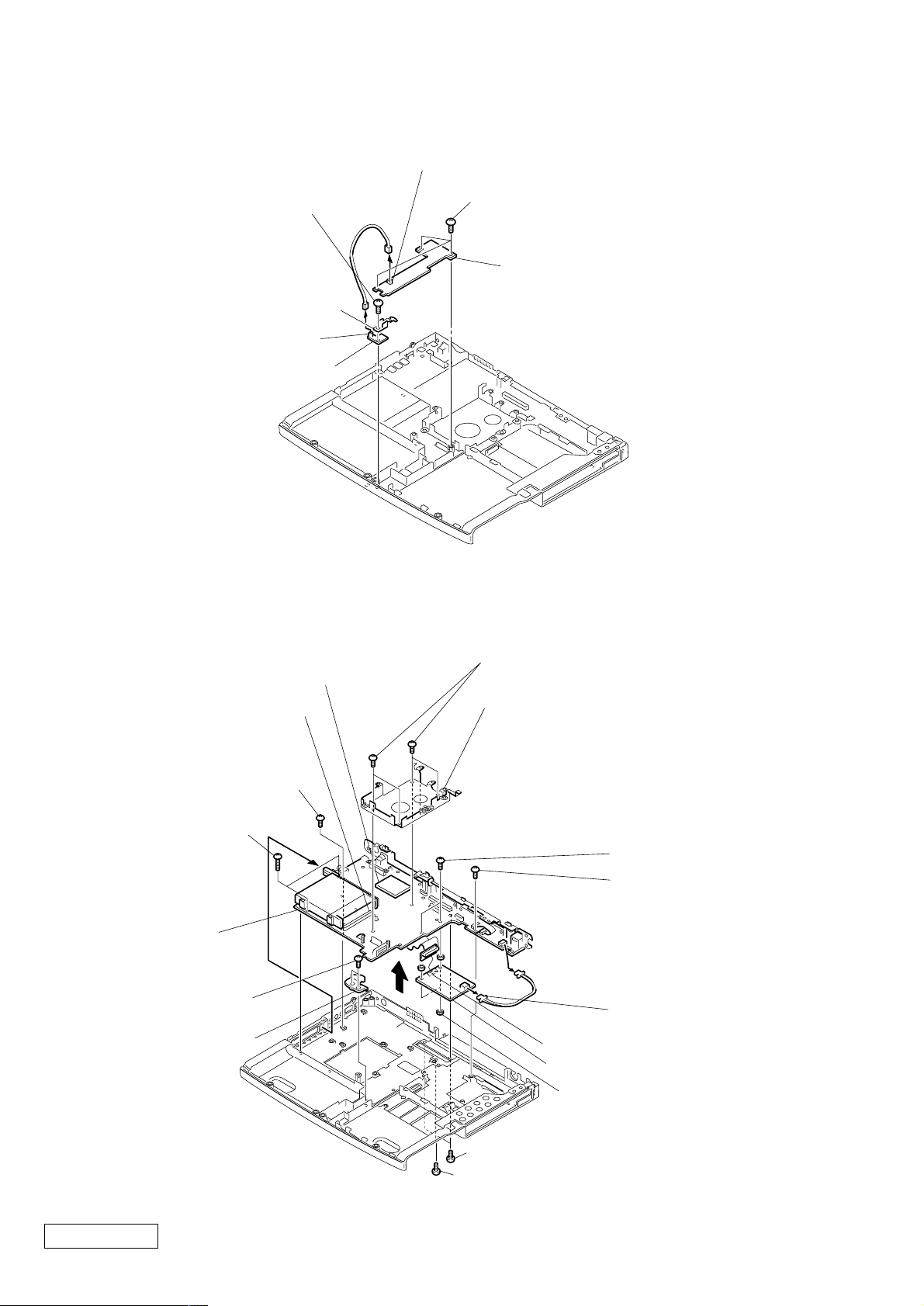
5. SWX-57 Board, Latch Detector Unit, PWS-9 Board
PWS-9 Board BCN3
3M2X4 Special Head
4Latch Detector Unit
SWX-57 Board CN5101
4SWX-57 Board
6. Modem Unit, MBX-39 Board
1M2X4 Special Head (X3)
2PWS-9 Board
MBX-39 Board CON7
4M2X4 Special Head
3+B 2X18 (X2)
MBX-39 Board
5M2X4 Special Head
(X2)
Bracket Bay Connector
∗1
When removing the CPU, refer to
“1-4. Replacing the CPU”.
CPU
1
∗
2HDD Bracket
5M2X6 Special Head (X2)
5M2X4 Special Head
9
1M2X6 Special Head(X4)
8
9
Modem Unit J2
Modem Unit J1
Modem Unit
q;
Nut M2 Type2 (X2)
7M2X4 Special Head(X2)
6M2X4 Special Head
Confidential
PCG-F610/F630 (UC)
1-4
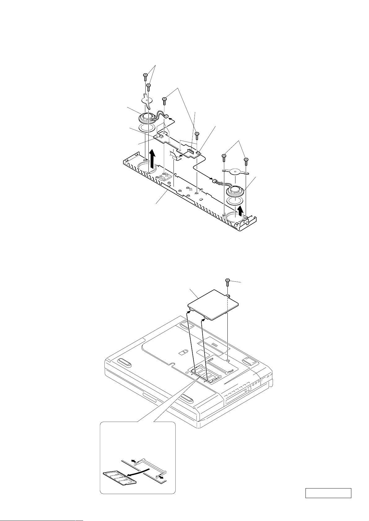
7. Speaker Unit, SWX-56 Board
3M2X4 (X2)
2M2X4 (X5)
8. SO-DIMM
Speaker Unit
SWX-56 Board
SWX-56 Board
JP1
1
Hood Keyboard
SWX-56 Board
JP2
SWX-56 Board
JP3
3M2X4 (X2)
1
1
Speaker Unit
2DIMM Door
Removal of SO-DIMM
a → b
a
1M2X4 Special Head
b
a
1-5
Confidential
PCG-F610/F630 (UC)

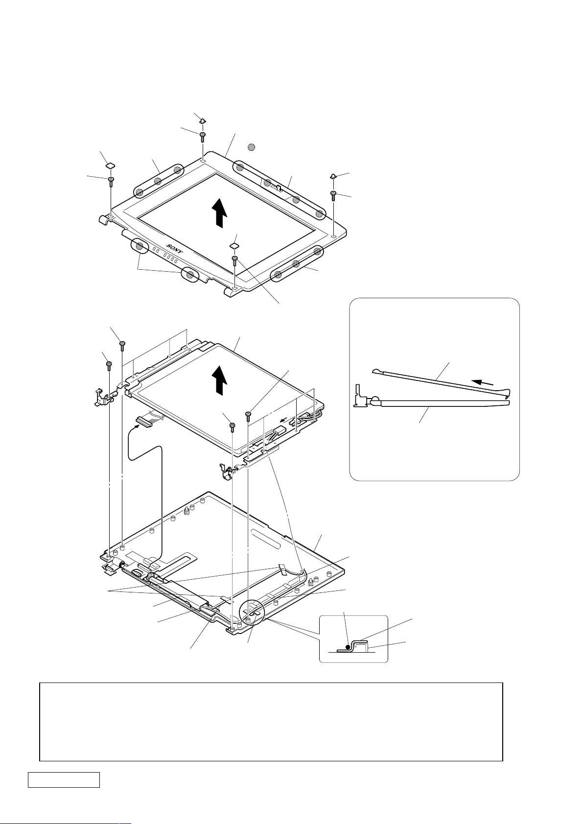
9. LCD Section (F630 Model) – Made by SA –
1. Bezel Housing Assy
1Lower Screw Cover (x2)
4M2X4
Special
Head (X4)
2M2X4
Special
Head (X2)
B
C
3
Bezel Housing Assy
: claw part
A
LCD Unit
7
1Upper Screw Cover (x2)
2M2X4
Special
Head (X2)
B
How to release the claw A.
Bezel Housing Assy
A
5
Inverter Assy
Inverter Assy
CN2
6
Display Housing Assy
4M2X4
Special
Head (X4)
Pull the Bezel Housing Assy
as shown to release the claw A.
Order of releasing the claws C → B → A
Order of locking the claws A → B → C
Display Housing Assy
Confidential
PCG-F610/F630 (UC)
1-6
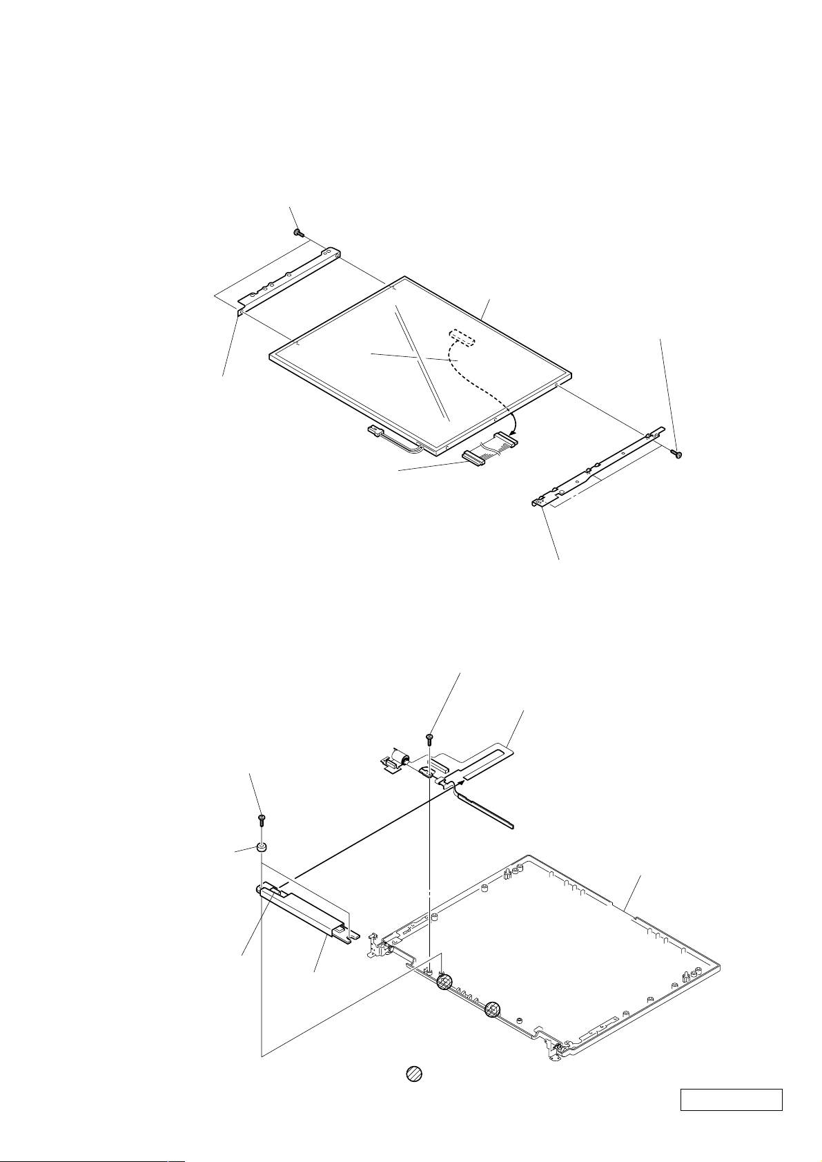
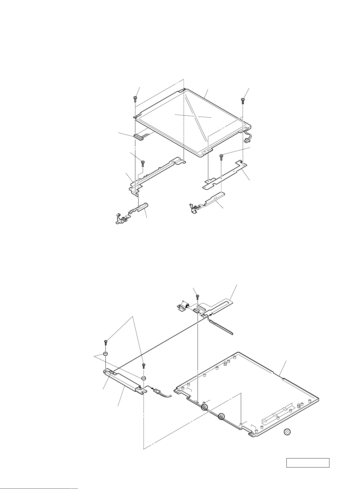
2. LCD Harness, Bracket LCD Left, Bracket LCD Right, LCD Unit (13inch)
2+P M2X3 Lock (X2)
LCD Unit
2+P M2X3 Lock (X3)
Bracket LCD Left
1
LCD
Harness
3. FPC, Inverter Assy, Display Housing Assy
2M2X4
Special Head
3M2X4
Special
Head (X2)
Inverter Bracket
Inverter Assy
CN1
Inverter Assy
Bracket LCD Right
FPC
Display Housing Assy
: claw part
1-7
Confidential
PCG-F610/F630 (UC)
10. LCD Section (F610 Model) – Made by SA –
1. Bezel Housing Assy
1Upper Screw Cover
2M2X4 Special Head
1Lower Screw Cover
2M2X4
Special
Head
C
4M2X4
Special
Head (X4)
5+PS 2.6X5
B
Bezel Housing Assy
3
LCD Unit
8
5+PS 2.6X5
: claw part
A
1Lower Screw
Cover
B
2M2X4 Special Head
4M2X4
Special
Head (X4)
6
1Upper Screw Cover
2M2X4 Special Head
How to release the claw A.
Bezel Housing Assy
A
7
Display Housing Assy
Pull the Bezel Housing Assy
as shown to release the claw A.
Order of releasing the claws C → B → A
Order of locking the claws A → B → C
Display Housing Assy
Insurator (Harness INV)
Adhesive tape
(Filament tape)
Inverter Assy
Inverter Assy
Lamp Harness (Pink)
Lamp Harness (Pink)
Filament tape
CN2
Lamp Harness (White)
Adhesive tape
Bracket LCD Right
(Filament tape)
• When Lamp Harness is installed, fix the Lamp Harness (white) using the adhesive tape (Filament tape) on the
Display Housing Assy as sho wn. Route the Lamp Harness (pink) through the Insula tor (Harness INV) as shown.
• Attach the adhesive tape (Filament tape) as shown to prevent the Lamp Harness (pink) from going under the
Bracket LCD Right.
• Be careful not to cover the screw hole with adhesive tape (Filament tape).
Confidential
PCG-F610/F630 (UC)
1-8
2. LCD Harness, Bracket LCD Left, Bracket LCD Right, Hinge Left, Hinge Right, LCD Unit (12inch)
LCD Harness
M2X4 Special Head
Bracket LCD Left
M3X4 (X2)
Hinge Left
LCD Unit
M3X4 (X2)
M2X4 Special Head
Bracket LCD Right
Hinge Right
3. FPC, Inverter Assy, Display Housing Assy
2M2X4
Special Head
3M2X4
Special
Head (X2)
Inverter Bracket
Inverter Assy
CN1
Inverter Assy
FPC
1
Display Housing Assy
1-9
: claw part
Confidential
PCG-F610/F630 (UC)
 Loading...