

Sony Vaio PCGA-CRWD1 Service Manual
PCGA-CRWD1
SERVICE MANUAL
Ver 1-2001J
All the supplementary
information are attached
at the end of data files.
Update List
Lineup : PCGA-CRWD1
For American Area
US Model
Canadian Model
S400
Confidential
9-872-273-01
CD-RW/DVD-ROM DRIVE
Information in this document is subject to change without notice.
Sony and VAIO are trademarks of Sony . Intel logo and Intel Inside
logo are registered trademarks of Intel Corporation. Pentium MMX
is a trademark of Intel Corporation. Microsoft, MS-DOS, W indows,
the W indows 95 and W indows 98 log o are trademarks of Microsoft
Corporation.
All other trademarks are trademarks or registered trademarks of
their respective owners. Other tr ademarks and trade names may be
used in this document to refer to the entitles claiming the marks and
names or their produces. Sony Corporation disclaims any proprietary
interest in trademarks and trade names other than its own.
Caution Markings for Lithium/Ion Battery - The following or similar
texts shall be provided on battery pack of equipment or in both the
operating and the service instructions.
CAUTION: Danger of explosion if battery is incorrectly replaced.
Replace only with the same or equivalent type recommended by
the manufacturer. Discard used batteries according to the
manufacturer’s instructions.
CAUTION: The battery pack used in this de vice may present a f ire
or chemical burn hazard if mistreated. Do not disassemble, heat
above 100°C (212°F) or incinerate.
Dispose of used battery promptly.
Keep away from children.
CAUTION: Changing the back up battery.
• Overcharging, short circuiting, reverse charging, multilation or
incineration of the cells must be avoided to prev ent one or more of
the following occurrences; release of toxic materials, release of
hydrogen and/or oxygen gas, rise in surface temperature.
• If a cell has leaked or vented, it should be replaced immediately
while avoiding to touch it without any protection.
Service and Inspection Precautions
1. Obey precautionary markings and instructions
Labels and stamps on the cabinet, chassis, and components identify areas
requiring special precautions. Be sure to observe these precautions, as well
as all precautions listed in the operating manual and other associated
documents.
2. Use designated parts only
The set’s components possess important safety characteristics, such as
noncombustibility and the ability to tolerate large voltages. Be sure that
replacement parts possess the same safety characteristics as the originals.
Also remember that the 0 mark, which appears in circuit diagrams and
parts lists, denotes components that have particularly important safety
functions; be extra sure to use only the designated components.
3. Always follow the original design when mounting
parts and routing wires
The original layout includes various safety features, such as inclusion of
insulating materials (tubes and tape) and the mounting of parts above the
printer board. In addition, internal wiring has been routed and clamped so
as to keep it away from hot or high-voltage parts. When mounting parts or
routing wires, therefore, be sure to duplicate the original layout.
4. Inspect after completing service
After servicing, inspect to make sure that all screws, components, and wiring
have been returned to their original condition. Also check the area around
the repair location to ensure that repair work has caused no damage, and
confirm safety.
5. When replacing chip components...
Never reuse components. Also remember that the negati ve side of tantalum
capacitors is easily damaged by heat.
6. When handling flexible print boards...
•The temperature of the soldering-iron tip should be about 270C.
•Do not apply the tip more than three times to the same pattern.
•Handle patterns with care; never apply force.
Caution: Remember that hard disk drives are easily damaged by
vibration. Always handle with care.
ATTENTION AU COMPOSANT AYANT RAPPORT
À LA SÉCURITÉ!
LES COMPOSANTS IDENTIFÉS P AR UNE MARQUE 0 SUR LES
DIAGRAMMES SCHÉMA TIQUES ET LA LISTE DES PIÈCES SONT
CRITIQUES POUR LA SÉCURITÉ DE FONCTIONNEMENT. NE
REMPLACER CES COMPOSANTS QUE PAR DES PIÈSES SONY
DONT LES NUMÉROS SONT DONNÉS DANS CE MANUEL OU
DANS LES SUPPÉMENTS PUBLIÉS PAR SONY.
Confidential
PCGA-CRWD1 (AM)
— 2 —

TABLE OF CONTENTS
Section Title Page
CHAPTER 1. REMOVAL
1-1. Flowchart ......................................................................... 1-1
1-2. Removal ........................................................................... 1-1
1. Cabinet (Lower) ............................................................... 1-1
2. Plate Shield ...................................................................... 1-2
3. IFX-170 Board ................................................................. 1-2
4. IFX-174 Board, Combination Drive, Support PC Board,
Reinforcement, Cabinet (Upper) Assy.............................1-3
5. Combination Drive, Bezel (Com) Assy ........................... 1-3
(to 1-3)
CHAPTER 2. SELF DIAGNOSTICS ...................... 2-1
(to 2-1)
CHAPTER 3. BLOCK DIAGRAM ·
FRAME HARNESS DIAGRAM........ 3-1
3-1. Block Diagram................................................................. 3-1
3-2. Frame Harness Diagram .................................................. 3-2
(to 3-2)
CHAPTER 4. DIAGRAMS............................................. 4-1
4-1. Semiconductors Index...................................................... 4-1
Semiconductor Pin Assignments ..................................... 4-2
4-2. Schematic Diagrams and Printed Wired Boards Index.... 4-7
1. IFX-170 Board .................................................................4-9
2. IFX-174 Board ...............................................................4-25
(to 4-32)
CHAPTER 5. EXPLODED VIEWS AND
PARTS LIST............................................5-1
(to 5-2)
— 3 —
Confidential
PCGA-CRWD1 (AM)

MEMO
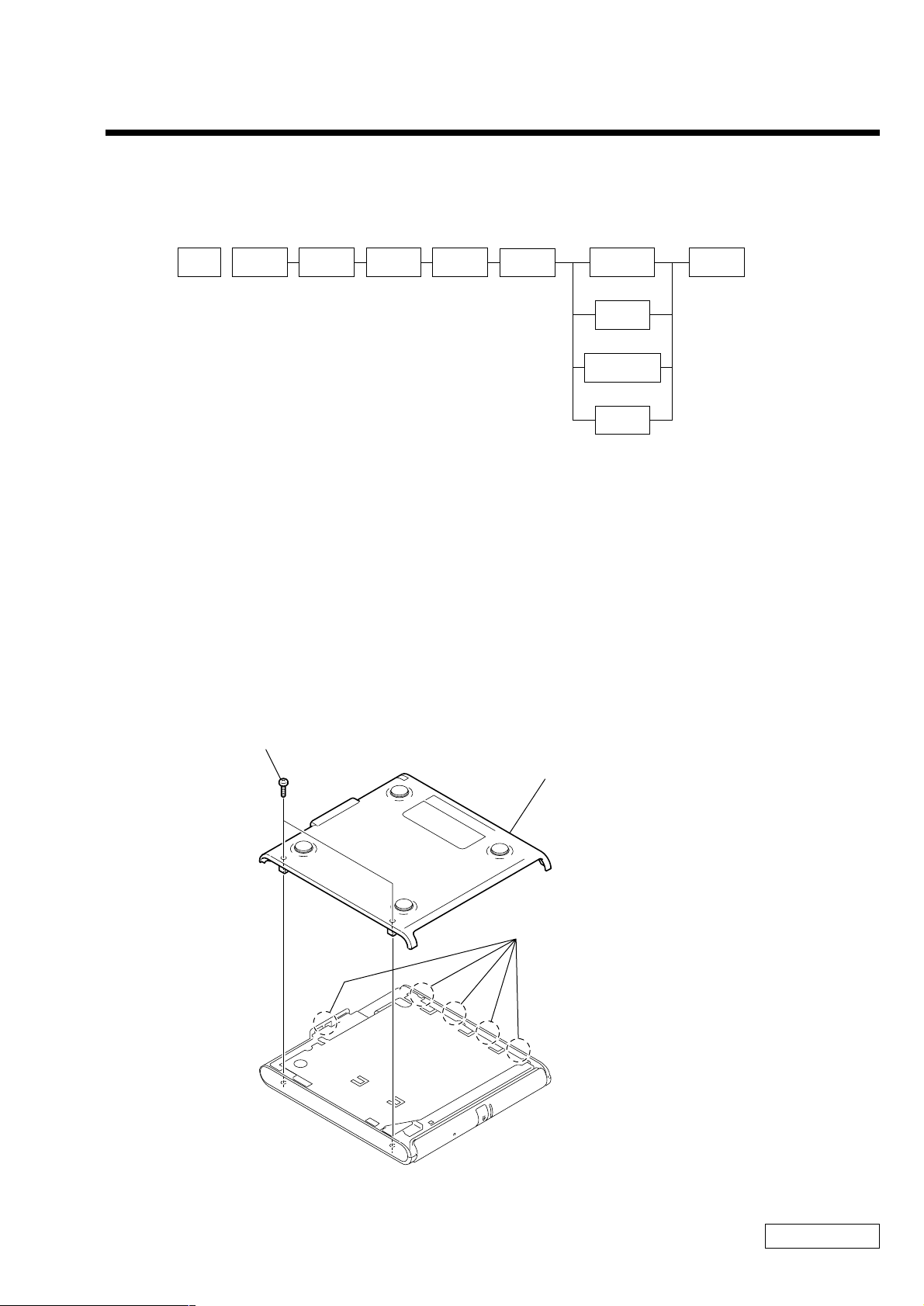
1-1. Flowchart
CHAPTER 1.
REMOVAL
POWER
OFF
CABINET
(LOWER)
PLATE
SHIELD
P 1-2
IFX-170
BOARD
P 1-2P 1-1
• P XX means pages that appears in this manual.
1-2. Removal
1. Cabinet (Lower)
FLEXIBLE
FLAT
CABLE
P 1-2
CABINET
(UPPER)
ASSY
P 1-3
COMBINATION
DRIVE
P 1-3
SUPPORT
PC BOARD
P 1-3
REINFORCEMENT
P 1-3
IFX-174
BOARD
P 1-3
BEZEL
(COM)
ASSY
P 1-3
1Screw (P2X8) (X2) (Black)
2Cabinet (Lower)
Remove the lower cabinet while being
careful not to break the claws (5 claws).
1-1
Confidential
PCGA-CRWD1 (AM)

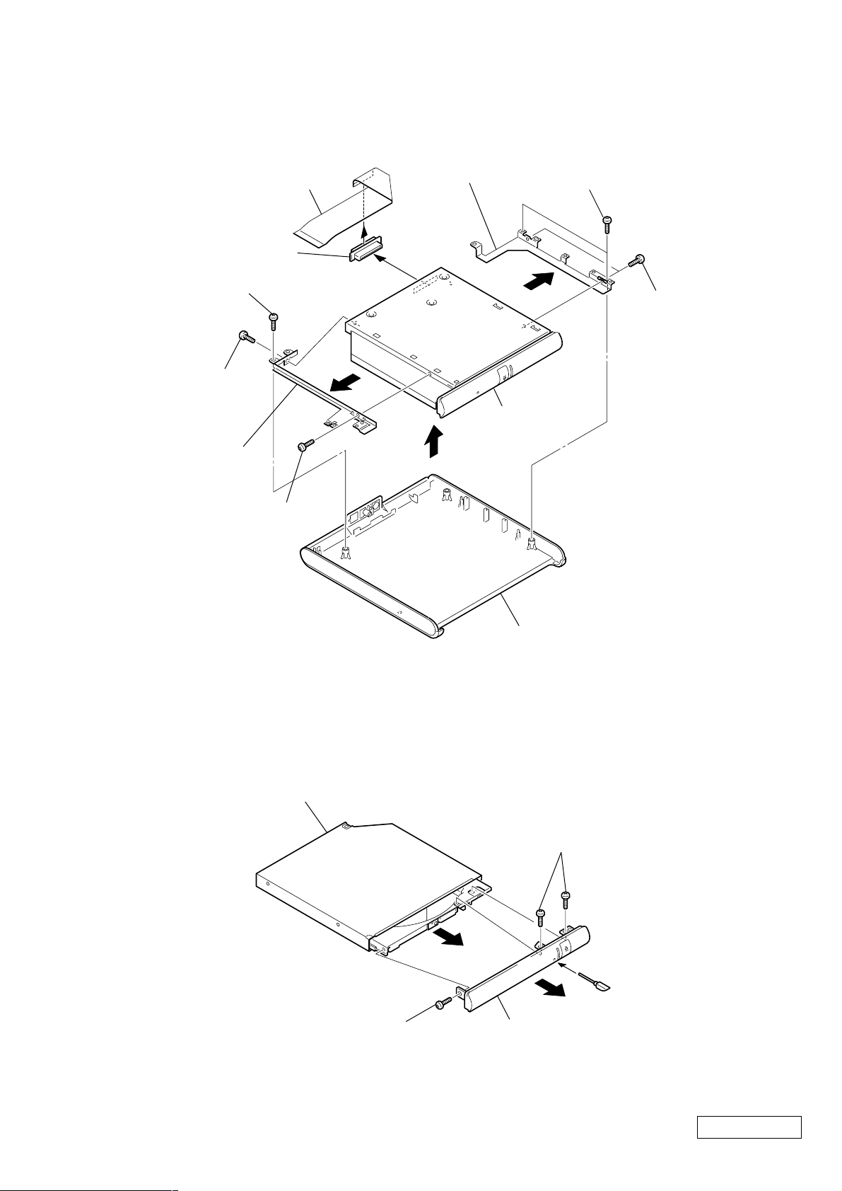
2. Plate Shield
2Screws (P2X2.5) (X2)
(Silver)
When attaching the spacer, protrude
the spacer exceeding the outer edge
of plate shield by 1mm.
4Spacer
1Screws (P2X2.5) (X2)
(Silver)
3Plate Shield
3. IFX-170 Board
2Screws (P2X2.5) (X2)
(Silver)
4IFX-170 Board
2Screw (P2X2.5) (Silver)
1Sheet
When attaching the sheet, align the sheet
with the corner of the combinaton drive.
Flexible Flat Cable
Combination Drive
3
Confidential
PCGA-CRWD1 (AM)
1-2
3Screws (P2X2.5) (X2)
(Silver)
1Screws (P2X6) (X2) (Black)
1Screws (P2X6) (Black)
3Screw (P2X2.5)
(Silver)
IFX-174 Board
Flexible Flat Cable
Cabinet (Upper) Assy
Support PC Board
Reinforcement
Combination
Drive
3Screw (P2X2.5)
(Silver)
2
4
6
4
5
4. IFX-174 Board, Combination Drive, Support PC Board, Reinforcement, Cabinet (Upper) Assy
5. Combination Drive, Bezel (Com) Assy
COMBO Drive
3Screw (M1.7X3.5) 0 Plate
Special Head (B) (Black)
3Screw (M1.7X3.5) TITE, 0 Plate
Special Head (B) (Black)
2
1Pin, Eject
Bezel (Com) Assy
1-3
(END)
Confidential
PCGA-CRWD1 (AM)

MEMO
CHAPTER 2.
SELF DIAGNOSTICS
ATTENTION
Please confirm “Self Diagnostics” method which will be informed you with distribution
of “Self Diagnostics” software.
Confidential
2-1 PCGA-CRWD1 (AM)
(END)

MEMO
BLOCK DIAGRAM · FRAME HARNESS DIAGRAM
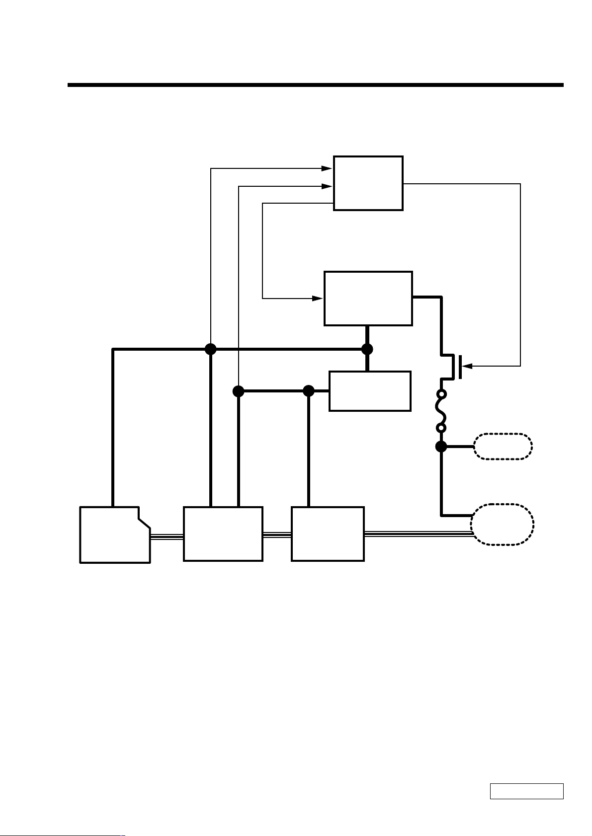
3-1. Block Diagram
CHAPTER 3.
Ditect
5.0V
3.3V
Ditect
Disable
OVP CIRCUIT
DC/DC Converter
LINEAR_LTC1735
IC300
Q303
Close
3.3V Regurator
RICOH_RN5RF33A
IC203
F300
DC-Jack Connector
CN300
CD-RW/
DVD-ROM Drive
KME_UJDA710
1394 Bridge
EPSON_SPC7281
1394 PHY
FFM_MD8408B
IC202IC2001-796-072-21
1394+POWER Connector
MOLEX_549490-0611
CN203
Confidential
3-1 PCGA-CRWD1 (AM)
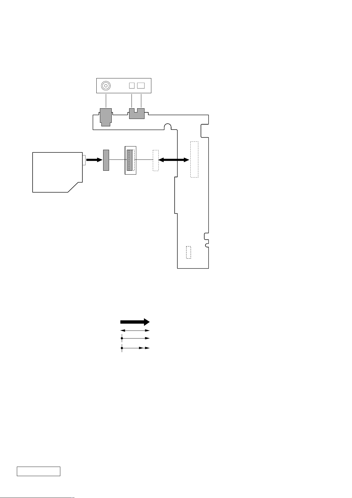
3-2. Frame Harness Diagram
149
2P
i.linkDC INDC IN 10V
4P
50
50
Combination
DRIVE
50 2
IFX-174 Board
(Side A)
1
CN200
1
IFX-170 Board
(Side A)
1
CN201
10
From board to connector (direct connection)
Harness (connector at both end)
Harness (soldered at one end)
Connectors soldered on board and appearing on the panel
Confidential
3-2PCGA-CRWD1 (AM)
(END)
 Loading...