

Sony Trinitron KV-37XBR48M, Trinitron KV-34XBR48C, Trinitron KV-35XBR88, Trinitron KV-35XBR48, KV-32XBR48 Operating Instructions Manual
...
SONY
Trinitron _Color TV
Operating Instructions
KV-32XBR48
KV-34XBR48C
KV-35XBR48
KV-35XBR88
KV-37XBR48M
© 1997 by Sony Corporation
Welcome!
Thank you for purchasing the Sony Trinitron ®
Color TV. This manual is for models
KV-32XBR48, 34XBR48C, 35XBR48, 35XBR88
and 37XBR48M.
Model KV-35XBR48 is used for illustration
purposes. Differences in operation are
indicated in the text; for example,
"KV-35XBR48 only".
The features you will enjoy include:
• Two ON/OFF TIMERS
• Picture-in-Picture (PIP) and Picture &
Picture (P&P) (Twin View TM)
• FAVORITE CHANNEL feature, allowing
you to view and choose from eight of your
favorite programs
• CHANNEL INDEX feature, allowing you
to view and choose from twelve programs
• Customized on-screen menus
• One Y/B-Y/R-Y input for DVD Player
connection
• Three AUDIO/VIDEO inputs
• Two S Video inputs
Precautions
Safety
• Operate the TV only on 120 V AC
(except KV-34XBR48C)
• Operate the TV on 220 V AC
(KV-34XBR48C only)
• The plug is designed, for safety purposes,
to fit into the wall outlet only one way. If
you are unable to insert the plug fully into
the outlet, contact your dealer.
(except KV-34XBR48C)
• If any liquid or solid object should fall inside
the cabinet, unplug the TV immediately and
have it checked by qualified service
personnel before operating it further.
• If you will not be using the TV for several
days, disconnect the power by pulling the
plug itself. Never pull on the cord.
For details concerning safety precautions, see the
supplied leaflet "IMPORTANT SAFEGUARDS".
Installing
• To prevent internal heat buildup, do not
block the ventilation openings.
• Do not install the TV in a hot or humid
place, or in a place subject to excessive
dust or mechanical vibration.
The AC power cord is attached to the rear of
the TV with hooks. Do not attempt to remove
the cord from these hooks. Doing so could
cause damage to the TV. (see "Note on AC
Power Cord" on page 2)
Using This Manual
This manual is divided into four major
sections. We recommend that you carefully
review the contents of each section in the
order provided to ensure that you fully
understand the operation of your new TV.
1 Installing and Connecting the TV.
This section will guide you through your
initial set up. It -will show you how to
your antenna or cable, and connect any
accessories.
Basic Set Up.
This section will teach you the basic skills
needed to operate your new TV. It will
show you how to operate special functions
of the remote control.
3 Using your New TV.
This section will show you how to begin
using your new TV. It will show you how
to use the AUTO SET UP feature, and how
to use your remote control's features.
4 Adjusting your Set Up (menus).
This section will teach you how to access
on-screen menus and adjust your TV's
settings.
Instructions in this ,_mual atv written jor theremote
control.Sbnilar controls trulybefound on theTV console.
.=in a residenl
generates, us
=nergy and, if
with the instf
: with radio o
_uarantee tha
ar installatior
:ul interferenc
thich can be c
_ff and on, th
nterference b
easures:
_r relocate th,
he separatior
he equipmenl
from that to \
I.
=e dealer or a_
for help.
Jtioned that
_ns not expre_
dd void your
ltisforthe r¢
-32XBR48,34
35XBR88,37
Table of Contents
Welcome! ........................................ 1
Precautions ...................................... 1
Using This Manual .......................... 1
Connecting and Installing the TV
Note on AC Power Cord ............................ 2
Connector Types .......................................... 2
Making Connections ................................... 2
Connecfialg directly to cable
or an antenna ....................................... 2
Cable or m_telma ...................................... 3
Cable and anteima .................................... 3
Connecting a. cable box ............................ 3
Cable box and cable .................................. 3
Connecting an antelma/cable TV system
with a VCR .......................................... 4
Connecting to an S Video equipped
VCR ..................................................... 4
Connecting a VCR and TV with a cable
box ....................................................... 5
Connecting to an S Video equipped VCR
with a cable box ................................. 5
Connecting a DBS receiver ...................... 6
Connecting a DBS receiver and a VCR .... 6
Connecting an audio system ................... 7
Connecting an AV receiver ...................... 7
Connecting two VCRs for tape editing
using MONITOR OUT ....................... 8
Connecting a DVD Player ....................... 9
Connecting a DVD Player with component
video output connectors ...................... 9
Connecting a camcorder ........................ 10
Using the S-Link function ...................... !1
Using the CONTROL S feature ............ 12
Using the Console Box
(KV-35XBR88 only) .......................... 13
Basic Set Up
h_serting Batteries......................................... 14
Using the Remote Control Joystick .............. 14
Adjusting Sliders .......................................... 14
On Line Help/Instructions .......................... 14
Using your New TV
Setting Up the TV Automatically ................. 15
Watching the TV .......................................... 16
Watching Two Programs at One Time
- PIP/P&P (Twin ViewS9 ................ 18
Using CHANNEL INDEX ........................... 20
Adjusting your SET UP (menus)
Leamhlg Menu Selection ............................. 22
Using the VIDEO Menu ............................... 23
Using the AUDIO Men_L.............................. 24
Using the TIMER Menu ............................... 25
Using tee SET UP Menu ............................. 26
Setting and Selecting
FAVORITE CHANNEL ..................... 28
Custon_zing the Menu ................................ 31
Operating Video Equipment
Setting the Manufacturer's CcKte ................. 32
Operating a Cable Box or DB5 Receiver
Settin,gtheManufacturet's Code ................. 34
Troubleshooting ........................... 35
Specifications ................................ 37
Index .............................................. 38
Owner's Record
The model and serial numbers are located at the rear
of the I"V, below the Sony logo, ore, the sticker, and
also on the TV box (white label). Record these numbers
in the spaces provided below. Refer to them whenever
you call upon your Sony dealer regarding this product•
Model No. KV-
Serial No.
2_
q,
i:):
,:2
7""
i'!
_ _ Connecting and Installing the TV
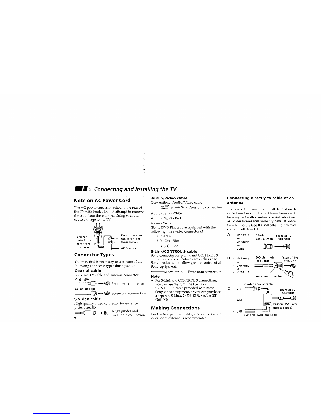
Note on AC Power Cord
The AC power cord is attached to the rear of
the TV with hooks. Do not attempt to remove
the cord from these hooks. Doing so could
cause damage to the TV.
YOU can _=_l_
detachtheI I _ 1
cordfrom--_ I
this hook _ _.
Do not remove
the cord from
these hooks.
-- AC Power cord
Connector Types
You may find it necessary to use some of the
following connector types during set up.
Coaxial cable
Standard TV cable and antenna connector
PlugType
__ -'_ (_ Press onto connection
Screw-on Type
_ _ Screw onto connection
S Video cable
High quality video connector for enhanced
picture quality
_ _) Align guides and
press onto connection
2
Audio/Video cable
Conventional Audio/Video cable
_Z_ _ (_ Press onto connection
Audio (Left) - White
Audio (Right) - Red
Video - Yellow
(Some DVD Players are equipped with the
following three video connectors.)
Y - Green
B-Y (Cb) - Blue
R-Y (Cr) - Red
S-Link/CONTROL S cable
Sony connector for S-Link and CONTROL S
connections. These features are exclusive to B
Sony products, and allow greater control of all
Sony equipment.
--_::E23_ _ _ Press onto connection
Note:
• For S-Link and CONTROL Sconnections,
vou can use the combined S-Link!
CONTROL S cable provided with some C
Sony video equipment, or you can purchase
a separate S-Link/CONTROL S cable (RK-
G69HG).
Making Connections
For the best picture quality, a cable TV system
or outdoor antenna is recommended.
Connecting directly to cable or an
antenna
The connection you choose will depend on the
cable found in your home. Newer homes will
be equipped with standard coaxial cable (see
A); older homes will probably have 300-ohm
twin lead cable (see B); still other homes may
contain both (see C).
A °
VHF only 75-ohm (Rear of TV)
or coaxial cable VHF/UHF
VHF/UHF
or
Cable
VHF only 300-ohm twin (Rear of TV)
lead cable VHF/UHF
or c_
UHF only _:_ _,._
or
VHF/UHF
Antenna
75-ohm coaxial cable
VHF __"! (Rear of TV)
and __
EAC-66 U/V mixer
(not
supplied)
UHF I
300-ohm twin lead cable
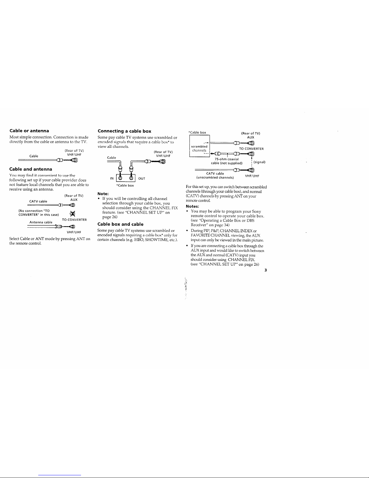
Cable or antenna
Most simple connection. Connection is made
directly from the cable or antenna to the TV.
Cable
v,=,=, of TV)
VHFIUHF
Cable and antenna
Ynu may find it convenient to use the
following set up if your cable provider does
not feature local channels that you are able to
receive using an antenna.
CATV cable
(Rear of TV)
AUX
cD---._
(No connection "TO
CONVERTER" in this case)
TO CONVERTER
Antenna cable
VHF/UHF
Select Cable or ANT mode by pressing ANT on
the remote control.
Connecting a cable box
Some pay cable TV systems use scrambled or
encnded signal_ that requiro a cahlo hnw* ta
view all channels.
(Rear of TV)
VHF/UHF
Cable
| |
I • t I
,N I OUT
*Cable box
Note:
• If you will be controlling all channel
selection through your cable box, you
should consider using the CHANNEL FIX
feature. (see "CHANNEL SET UP" on
page 26)
Cable box and cable
Some pay cable TV systems use scrambled or
encoded signals requiring a cable box* only for
certain channels (e.g. HBO, SHOWTIME, etc.).
*Cable box (Rear of TV)
... AUX
I
scrambled __s_
r_ .... io TO CONVERTER
I.........':"
75-ohm coaxial {
cable (not supplied) i (signal)
i
CATV cable
(unscrambled channels) VHF!UHF
Forthis set up, you can switch between scrambled
channels (through your cable box), and normal
(CAT_,Od_nnels by pressing ANT on your
remote control.
Notes:
• You may be able to program your Sony
remote control to operate your cable box.
(see "Operating a Cable Box or DBS
Receiver" on page 34)
• During PIP, P&P, CHANNEL INDEX or
FAVORITE CHANNEL viewing, the AUX
input can only be viewed in the main picture.
• If you are com_ecting a cable box through the
AUX input and would like to switch between
the AUX and normal (CATV) input you
should consider using CHANNEL FIX.
(see "CHANNEL SET UP" on page 26)
.:(

J_
"9
,7
_m Connecting and Installing the TV (continued)
Connecting an antenna/cable TV
system with a VCR
1 Attach the coaxial connector from your
cable or antenna to IN on your VCR.
2 Using AUDIO/VIDEO connectors, connect
AUDIO and VIDEO OUT on your VCR to
AUDIO and VIDEO IN on your TV
(Yellow-VIDEO, White-AUDIO Left, Red-
AUDIO Right).
3 Using a coaxial connector, connect OUT on
your VCR to VHF/UHF on your TV.
Connecting to an S Video equipped
VCR
Disconnect all power sources before making any connections.
Coaxial cable
3
VCR
(Rear of TV)
ff woc_3
Cable I_ °"T
1,,,-..,.-=¢..f._,.
CONinT{B
...............
OUT (Q/
AUDIO-L (white)
VIDEO (yellow)
!
2 VMC-810S/820S (not supplied)
1 Attach the coaxial connector from your
cable or antenna to IN on your VCR.
2 Using AUDIO connectors, connect AUDIO
OUT on your VCR to AUDIO IN on your TV
(White-AUDIO Left, Red-AUDIO Right).
3 Using a coaxial connector, connect OUT on
,yu_l v_,-l\ t',_ vla, l / ,,_.,1_1 ,JJl ),_pul • v.
4 Using an S VIDEO connector, connect
S VIDEO on your VCR to S VIDEO on
your TV.
Note:
• if you are connecting a monaural VCR,
connect only the single audio output to the
left (MONO) input on your TV.
3
(Rear of TV)
TO " _ V
Coaxial cable ,,_o
VCR _ I_
AUO_ORAUOK_t_vEo s vloEo
U ,v,o o
YC-15V/30V AUDIO-R (red)
4 (not supplied) AUDIO-L (white)
2 T
RK-74A (not supplied)
4
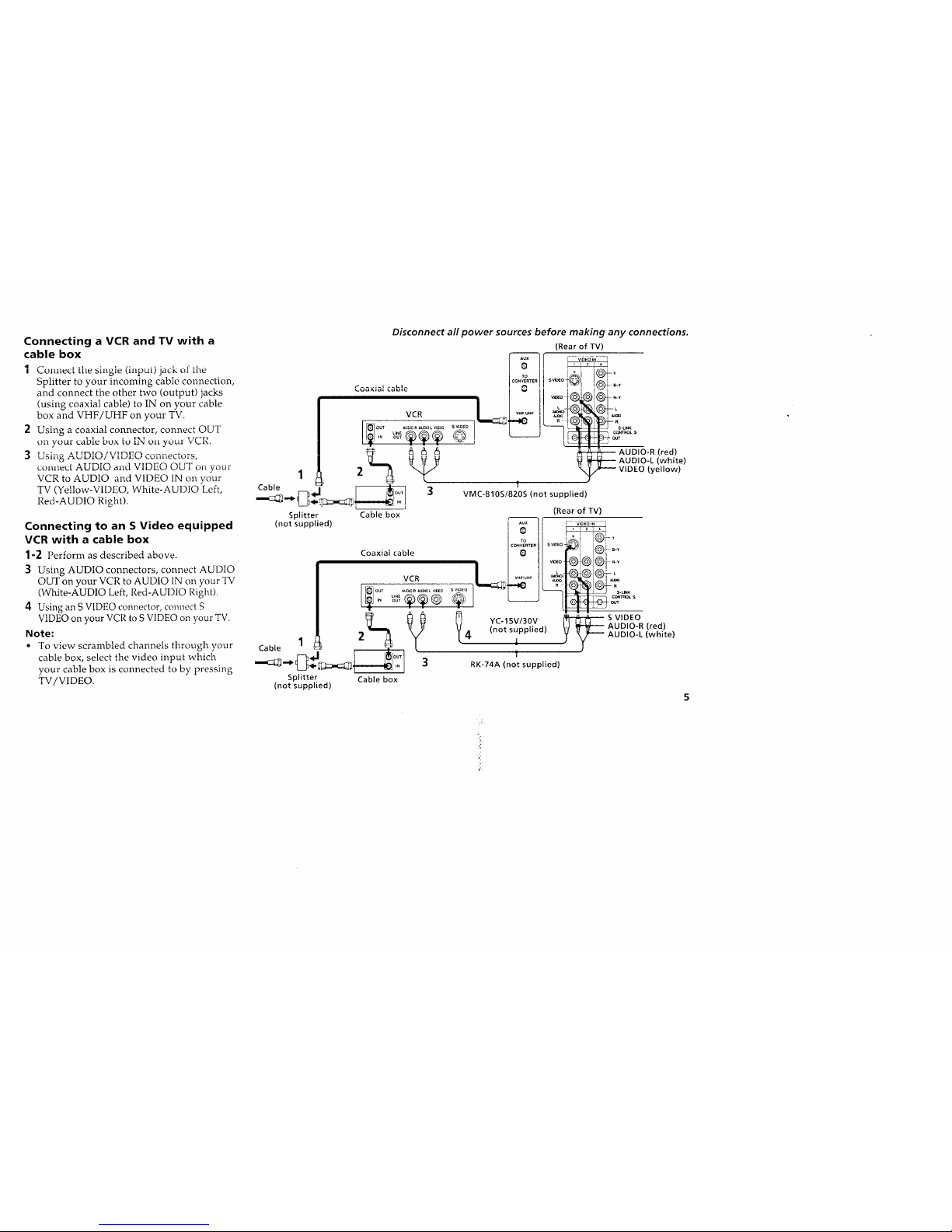
Connecting a VCR and TV with a
cable box
1 ColtllecL " - , ,: _ ,_ :___. _c,,__
UI LILt2
)clL_I_the _m_le _,Ht_pUt/
Splitter to your incoming cable connection,
and connect the other two (output) jacks
(using coaxial cable) to IN on your cable
box and VHF/UHF on your TV.
2 Using a coaxial connector, connect OUT
on your cable box to IN on your VCR.
'_ It_:__ _ ATTT_,Tn IlylT_.r.'_x, ......... _ ....
J UDIJ. L_ .z_Xt-JJ-."J._.,"/ V J. LJJ£,'.,...,' L.UILIL_'_LUID,
.... ATT • anu vIDL,,aOu_ onyour
COItlteCt ./-kLJalo _. a ,t 7 e¢'_ • TT
VCR to AUDIO and VIDEO IN on your
TV (Yellow-VIDEO, White-AUDIO Left,
Red-AUDIO Right).
Connecting to an S Video equipped
VCR with a cable box
1-2 Perform as described above.
3 Using AUDIO connectors, connect AUDIO
OUT on your VCR to AUDIO IN on your TV
(White-AUDIO Left, Red-AUDIO Right).
4 Using an S VIDEO connector, connect S
VIDEO on your VCR to S VIDEO on your TV.
Note:
• To view scrambled channels through your
cable box, select the video input which
your cable box is connected to by pressing
TV/VIDEO.
Cable -- i ,11,, i
Splitter Cable box
Disconnect all power sources before making any connections.
(Rear of TV)
To _ v
r .... :_l --LI-
OUT IUDIO R AUtO L VLD[O S VI_O S._
....®®®
In OUT
.... t_ _
_ _ _ _ AUDIO-R (red)
_ _ _ _ _ AUDIO-L (white)
2 _ f _ VIDEO(yeiiow)
3 VMfi-810S/820S (not supplied)
(Rear of TV)
(not supplied)
Splitter Cable box
(not supplied)
i 'l/
to
CONVERTER sv_el
Coaxial cable 0
V_EC
VCR 1L .....u._ _
Q_ _ YC-15V/30V
2 4 (notsupplied)
!
3 RK-74A (not supplied)
®:®
S VIDEO
AUDIO-R (red)
AUDIO-L (white)
A
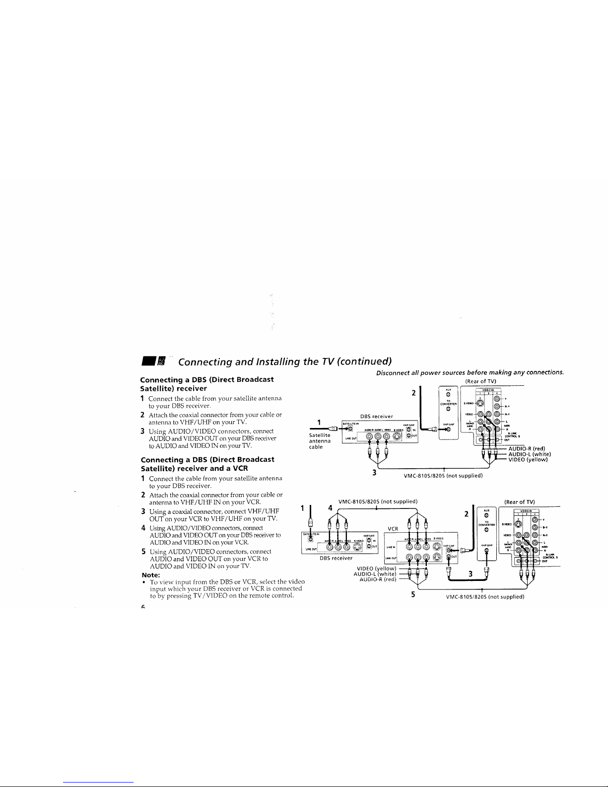
mm ,_
Connecting a DBS (Direct Broadcast
Satellite) receiver
1 Connect the cable from your satellite antenna
to your DBS receiver.
2 Attach the coaxial connector from your cable or
antenna to VHF/UHF on your TV.
3 Using AUDIO/VIDEO connectors, connect
AUDIO and VIDEO OUT on your DBS receiver
to AUDIO and VIDEO IN on your TV.
Connecting and Installing the TV (continued)
Disconnect all power sources before making any connections.
(Rear of TV)
Connecting a DBS (Direct Broadcast
Satellite) receiver and a VCR
1 Connect the cable from your satellite antenna
to your DBS receiver.
2 Attach the coaxial connector from your cable or
antenna to VHFiUHF IN on your VCR.
3 Using a coaxial connector, connect VHF/UHF
OUT on your VCR to VHF/UHF on your TV.
4 Using AUDIO/VIDEO connectors, coru-Lect
AUDIO and VIDEO OUT on your DBS receiver to
AUDIO and VIDEO IN on your VCR.
5 Using AUDIO/VIDEO connectors, connect
AUDIO and VIDEO OUT on your VCR to
AUDIO and VIDEO IN on your TV.
Note:
2
DBS receiver
1
Satellite I .....I © © © ©q L_o_
antenna _ --'_
cable
IO-R (red)
l_ I_ AUDIO-L (white)
- VIDEO (yellow)
3 T
VMC-810S1820S (not supplied)
VMC-810S/820S (not supplied)
, ........ '_]o":::,oo
', .... [DBfre_ce,v_er_l L_ 1
To view input from the DBS or VCR, select the video
input which your DBS receiver or VCR is connected
to by pressing TV/VIDEO on the remote control.
(Rear of TV)
VCR
I .LLL ..... I t
I I _K-K _t ......I/1 ..... [!
VIDEO (yellow)
AUD!_O-L(white,! _ _ 3
5 VMC-810S/820S (not supplied)
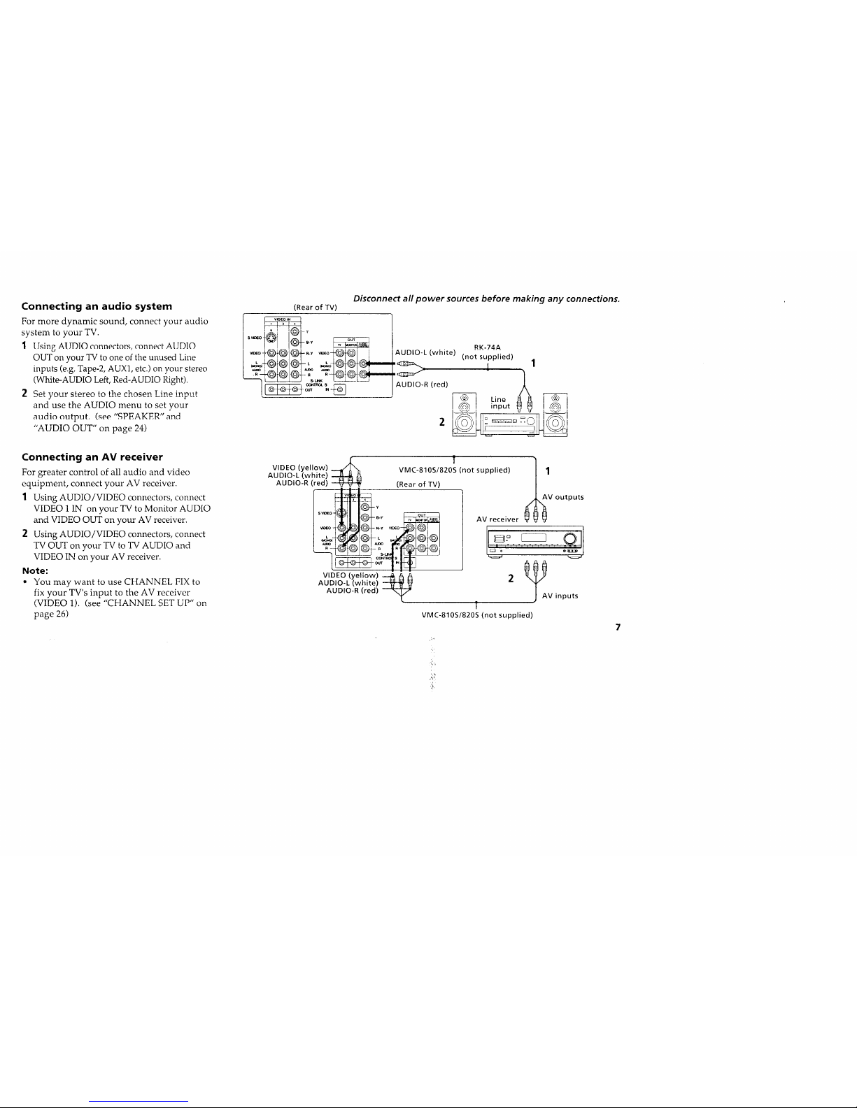
Connecting an audio system
For more dynamic sound, connect your audio
system to your TV.
1 Using ATJDTOconnect_rs, connect AUDIO
OUT on your TV to one of the unused Line
inputs (e.g. Tape-2, AUX1, etc.) on your stereo
(White-AUDIO Left, Red-AUDIO Right).
2 Set },our stereo to the chosen Line input
and use the AUDIO menu to set your
audio cmtput. (see "SPEAKER" and
"AUDIO OUT" on page 24)
Connecting an AV receiver
For greater control of all audio and video
equipment, connect your AV receiver.
1 Using AUDIO/VIDEO connectors, connect
VIDEO 1 IN on your TV to Monitor AUDIO
and VIDEO OUT on your AV receiver.
2 Using AUDIO/VIDEO connectors, connect
TV OUT on your TV to TV AUDIO and
VIDEO IN on your AV receiver.
Note:
° You may want to use CHANNEL FIX to
fix your TV's input to the AV receiver
(VIDEO 1). (see "CHANNEL SET UP" on
page 26)
Disconnect all power sources before making any connections.
(Rear of TV)
I _-oq_@)_lC_- .... -_o@_1 I I AUDIO-L (white) "noisu "lied"
input _ I
I i,o " CLHI i
VIDEO (yellow)
AUDIO-L (white)
AUDIO-R (red)
VIDEO (yellow)
AUDIO-L (white)
AUDIO-R (red)
' ]VMC-810S/820S (not supplied) 1
(Rear of TV) _AV outputs
000
AV receiver
2 _V inputs
T
VMC-810S/820S (not supplied)
'i
mJ iil
Connecting and Installing the TV (continued)
Disconnect all power sources before making any connections.
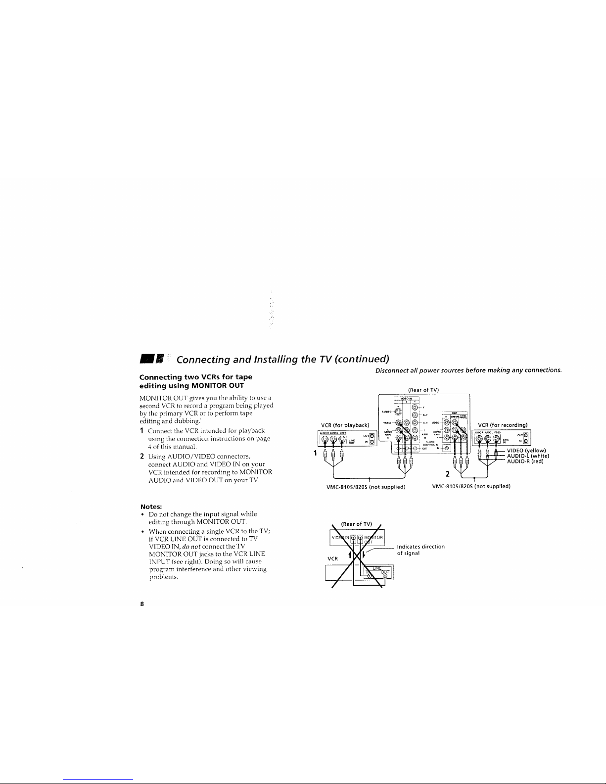
Connecting two VCRs for tape
editing using MONITOR OUT
MONITOR OUT gives you the ability to use a
second VCR to record a program being played
by the primary VCR or to perform tape
editing and dubbing."
1 Connect the VCR intended for playback
using the connection instructions on page
4 of this manual.
Using AUDIO/VIDEO connectors,
connect AUDIO and VIDEO IN on your
VCR intended for recording to MONITOR
AUDIO and VIDEO OUT on your TV.
VCR (for playback)
AU_ORAU_0L_O
LrNC
OUT IN
T
VMC-810S/820S (not supplied)
(Rear of TV)
_o _@1_ ..... ¢@_@1i
_ _ VIDEO (yellow)
_._ AUDIO-L (white)
,_ AUDIO-R (red)
2
VMC-810S1820S (not supplied)
Notes:
• Do not change the input signal while
editing through MONITOR OUT.
• When connecting a single VCR to the TV;
if VCR LiNE OUT is connected to TV
VIDEO IN, do not connect the TV
MONITOR OUT jacks to the VCR LINE
INPUT (see right). Doing so will cause
program interference and other viewing
1 1 .
(Rear of TV)/
__ Indicates direction
of signal
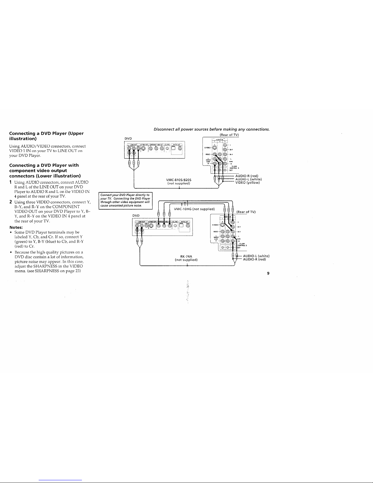
Connecting a DVD Player (Upper
illustration)
Using AUDIO/VIDEO connectors, connect
VIDEO 1 IN on your TV to LINE OUT on
your DVD Player.
Connecting a DVD Player with
component video output
connectors (Lower illustration)
1 T To;no- A T TT_TN _,_,_,_o_t-_rc r,o)_)_or_ A T TI-_T_"J
R and L of the LINE OUT on your DVD
Player to AUDIO R and L on the VIDEO IN
4 panel at the rear of your TV.
2 Using three VIDEO connectors, connect Y,
B-Y, and R-Y on the COMPONENT
VIDEO OUT on your DVD Player to Y, B-
Y, and R-Y on the VIDEO IN 4 panel at
the rear of your TV.
Notes:
• Some DVD Player terminals may be
labeled Y, Cb, and Cr. If so, connect Y
(green) to Y, B-Y (blue) to Cb, and R-Y
(red) to Cr.
Because the high quality pictures on a
DVD disc contain a lot of information,
picture noise may appear. In this case,
adjust the SHARPNESS in the VIDEO
menu. (see SHARPNESS on page 23)
!
Disconnect all power sources before making any connections.
(Rear of TV)
DVD
1 ........ t
I
[ VMC-810S/820S
(,,ut_upplied)
L
_r-fi_ A_u_m°_-R!red.).
_ AUUIU-L (willte)
• ,DE_ we,low_
Y
Connect your DVD Player directly to I
your TV. Connecting the DVD Piayel
!
throughunwantedOthervideo equipmentnoise,will I
(
cause picture I I
DVO
l
r 711
VMC-i0HG (not supplied)
RK-74A
(not supplied)
_ (Rear of TV)
sv_o _Y
v_o R-y
_ AUDIO-L{white)
AUDIO-R{red)
?:
A,
Zi
Connecting and Installing the TV (continued)
Disconnect all power sources before making any connections.
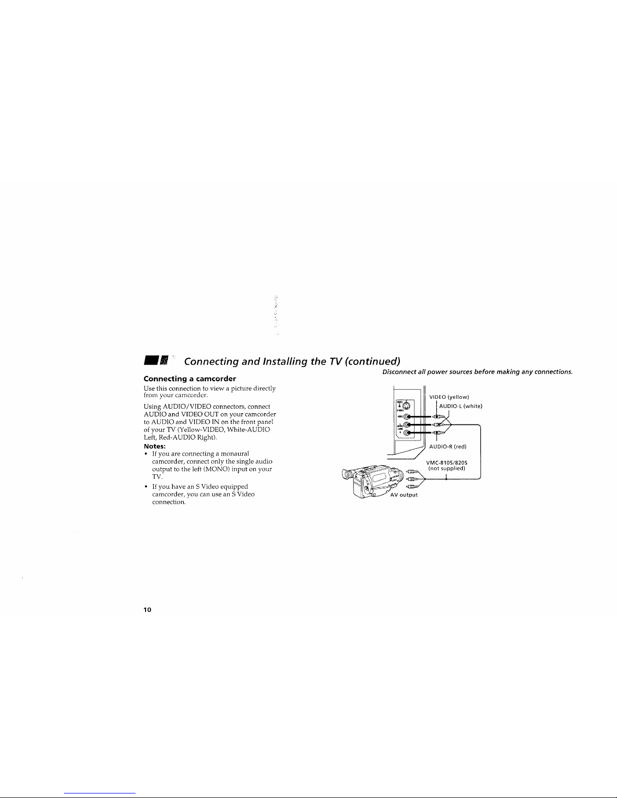
Connecting a camcorder
Use this connection to view a picture directly
from your camcorder.
Using AUDIO/VIDEO connectors, connect
AUDIO and VIDEO OUT on your camcorder
to AUDIO and VIDEO IN on the front panel
of your TV (Yellow-VIDEO, White-AUDIO
Left, Red-AUDIO Right).
Notes:
• If you are connecting a monaural
camcorder, connect only the single audio
output to the left (MONO) input on your
TV.
• If you have an S Video equipped
camcorder, you can use an S Video
connection.
VIDEO (yellow) )
AUDIO-R (red)
VMC-810S/820S
_ (not supplied)
_ AV output
10

Using the S-Link function
S-Link is a Sony innovation designed to make
your Sony components work together. It
allows you to automatically switch the TV
input mode to video when you Dress PI,AY on
your Sony S-Link VCR. It also ailows you to
turn the VCR and TV off at the same time
with the SYSTEM OFF button.
1 Connect your VCR. (see "Connectin_ an
antenna/cable TV system with a VCR" or
"Connecting to an S Video equipped VCR"
on page 4)
2 Using an S-LINK connector, connect the
S-LINK jacks on your VCR and TV. Ensure
that both ends are seated firmly and that
the TV S-LINK connector is in the same
row as the AUDIO/VIDEO connectors.
Disconnect all power sources before making any connections.
VCR
AIJ I')IO-R (rpd'h _ a a ,
AUDlO-L(whJiei _ _ mS-LINK
VIDEO (yellow) 1 _(black)
1
I
[
(Rear of TV)
r
L _ L L
R--- R R
J
z
i
Audio/Video/S-Link cable
(not supplied)
11
 Loading...