

Sony Trinitron KV-32XBR48, Trinitron KV-35XBR88, Trinitron KV-34XBR48C, Trinitron KV-37XBR48M, Trinitron KV-35XBR48 Operating Instructions Manual

S
3-860-371-21 (1)
®
®
Trinitron Color TV
Operating Instructions
KV-32XBR48
KV-34XBR48C
KV-35XBR48
KV-35XBR88
KV-37XBR48M
© 1997 by Sony Corporation

Table of Contents
Welcome! ........................................ 1
Precautions...................................... 1
Using This Manual .......................... 1
Connecting and Installing the TV
Note on AC Power Cord ............................2
Connector Types ..........................................2
Making Connections ...................................2
Connecting directly to cable
or an antenna ....................................... 2
Cable or antenna ...................................... 3
Cable and antenna ...................................3
Connecting a cable box ............................3
Cable box and cable .................................3
Connecting an antenna/cable TV system
with a VCR ..........................................4
Connecting to an S Video equipped
VCR .....................................................4
Connecting a VCR and TV with a cable
box .......................................................5
Connecting to an S Video equipped VCR
with a cable box................................. 5
Connecting a DBS receiver ...................... 6
Connecting a DBS receiver and a VCR.... 6
Connecting an audio system ................... 7
Connecting an AV receiver...................... 7
Connecting two VCRs for tape editing
using MONITOR OUT ....................... 8
Connecting a DVD Player ....................... 9
Connecting a DVD Player with component
video output connectors ......................9
Connecting a camcorder ........................ 10
Using the S-Link function ......................11
Using the CONTROL S feature ............12
Using the Console Box
(KV-35XBR88 only) ..........................13
Basic Set Up
Inserting Batteries......................................... 14
Using the Remote Control Joystick .............. 14
Adjusting Sliders .......................................... 14
On Line Help/Instructions ..........................14
Using your New TV
Setting Up the TV Automatically................. 15
Watching the TV .......................................... 16
Watching Two Programs at One Time
– PIP/P&P (Twin View
TM
) ................ 18
Using CHANNEL INDEX........................... 20
Adjusting your SET UP (menus)
Learning Menu Selection ............................. 22
Using the VIDEO Menu............................... 23
Using the AUDIO Menu ..............................24
Using the TIMER Menu ............................... 25
Using the SET UP Menu ............................. 26
Setting and Selecting
FAVORITE CHANNEL ..................... 28
Customizing the Menu ................................ 31
Operating Video Equipment
Setting the Manufacturer's Code ................. 32
Operating a Cable Box or DBS Receiver
Setting the Manufacturer's Code ................. 34
Troubleshooting ........................... 35
Specifications ................................ 37
Index.............................................. 38
Owner’s Record
The model and serial numbers are located at the rear
of the TV, below the Sony logo, on the sticker, and
also on the TV box (white label). Record these numbers
in the spaces provided below. Refer to them whenever
you call upon your Sony dealer regarding this product.
Model No.
Serial No.
KV-

Remote Control
In the instructions that follow, we will
refer to the buttons on your remote control.
Keep this flap unfolded and use this page
for reference.
SYSTEM OFF (page 17)
DISPLAY (page 17)
VCR/DVD/MDP
Operation
Buttons
(page 33)
DVD
Operation
Buttons
(page 33)
PIP/P&P
(pages 18, 19)
MUTING
VTR/DVD DBS/CABLE
VTR/DVD DBS/CABLE
TV/VTR
REC
TITLE DVD MENU FREEZE
AUDIO SWAP CH
POSITION TV/VIDEO CH
OFF
TV/DBS
FUNCTION
MUTING
(page 16)
SLEEP (page 17)
JUMP
(page 16)
POWER
TV
TV
/TV/DBS
VOL +/–
RESET
+
-
GUIDE
MTS
CODE SET
(pages 32, 34)
MUTING
VTR/DVD DBS/CABLE
FUNCTION
SYSTEM
VTR/DVD DBS/CABLE
SLEEP DISPLAY TV/VIDEO ANT
213
546
879
JUMP ENTER
0
OFF
TV/DBS
VOL
MENU
RESET
VTR 1 2 3 DVD/MDP
CODE SET
TV
POWER
TV
TVOFF
GUIDE
MTS
CH
RM -Y144
POWER
(page 16)
FUNCTION
(page 16)
ANT (page 17)
TV/VIDEO
(page 17)
0 – 9 Buttons
ENTER
PIP/P&P/
CHANNEL INDEX
(pages 18-21)
MTS/DBS Guide
MENU
CH +/–
Joystick
(page 14)
VTR1/2/3/DVD/
MDP (page 32)
Getting to know the buttons on the
remote control
Names of the buttons on the remote control are
presented in different colors to represent the
available functions.
Button color
Transparent .... Press to select the component
you want to control; e.g. VTR
(VCR)/MDP/DVD Player, DBS
(Direct Broadcast Satellite)/
CABLE, or TV.
Green ............... Buttons relevant to power
operations, like turning the TV,
DBS (Direct Broadcast Satellite)/
CABLE, or VTR (VCR)/MDP/
DVD Player on or off.
Label color
White ............... TV/VTR (VCR)/MDP/DVD
Player/DBS (Direct Broadcast
Satellite)/CABLE operation
buttons.
Yellow.............. PIP, P&P, and CHANNEL
INDEX operation buttons.
Blue .................. DBS (Direct Broadcast Satellite)
operation buttons.
Green ............... S-Link operation buttons.
Pink .................. DVD Player operation buttons.
For a detailed explanation of most buttons, see
"Watching the TV" on page 16.
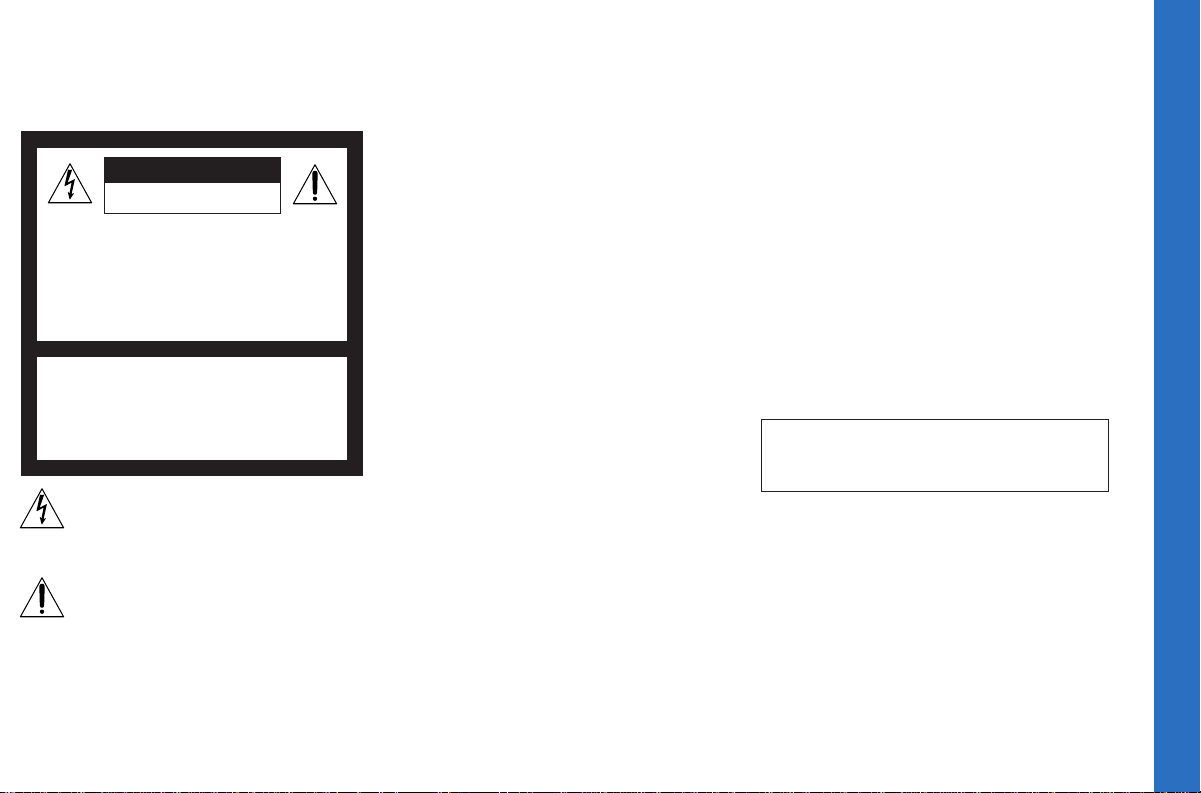
WARNING
To prevent fire or shock hazard, do not expose the TV
to rain or moisture.
CAUTION
RISK OF ELECTRIC SHOCK
DO NOT OPEN
ATTENTION
RISQUE DE CHOC ELECTRIQUE,
NE PAS OUVRIR
PRECAUCION
RIESGO DE CHOQUE ELECTRICO
NO ABRIR
CAUTION: TO REDUCE THE RISK OF ELECTRIC SHOCK,
DO NOT REMOVE COVER (OR BACK).
NO USER-SERVICEABLE PARTS INSIDE.
REFER SERVICING TO QUALIFIED SERVICE PERSONNEL.
This symbol is intended to alert the user to
the presence of uninsulated “dangerous
voltage” within the product’s enclosure that
may be of sufficient magnitude to constitute
a risk of electric shock to persons.
This symbol is intended to alert the user to
the presence of important operating and
maintenance (servicing) instructions in the
literature accompanying the appliance.
CAUTION
TO PREVENT ELECTRIC SHOCK, DO NOT USE THIS
POLARIZED AC PLUG WITH AN EXTENSION CORD,
RECEPTACLE, OR OTHER OUTLET UNLESS THE BLADES CAN
BE FULLY INSERTED TO PREVENT BLADE EXPOSURE.
CAUTION
When using TV games, computers, and similar products
with your TV, keep the brightness and contrast
functions at low settings. If a fixed (non-moving)
pattern is left on the screen for long periods of time at
a high brightness or contrast setting, the image can be
permanently imprinted onto the screen. Continuously
watching the same program can cause the imprint of
station logos onto the TV screen. These types of
imprints are not covered by your warranty because
they are the result of misuse.
Note on Caption Vision
This television receiver provides display of television
closed captioning in accordance with §15.119 of the
FCC rules.
Note on cleaning the TV
Clean the TV with a soft dry cloth. Never use strong
solvents such as thinner or benzine, which might
damage the finish of the cabinet.
Note to CATV system installer
This reminder is provided to call the CATV system
installer’s attention to Article 820-40 of the NEC that
provides guidelines for proper grounding and, in
particular, specifies that the cable ground shall be
connected to the grounding system of the building, as
close to the point of cable entry as practical.
Use of this television receiver for other than private
viewing of programs broadcast on UHF or VHF or
transmitted by cable companies for the use of the
general public may require authorization from the
broadcaster/cable company and/or program owner.
NOTIFICATION
This equipment has been tested and found to comply
with the limits for a Class B digital device pursuant to
Part 15 of the FCC Rules. These limits are designed to
provide reasonable protection against harmful
interference in a residential installation. This
equipment generates, uses, and can radiate radio
frequency energy and, if not installed and used in
accordance with the instructions, may cause harmful
interference with radio communications. However,
there is no guarantee that interference will not occur
in a particular installation. If this equipment does
cause harmful interference to radio or television
reception, which can be determined by turning the
equipment off and on, the user is encouraged to try to
correct the interference by one or more of the
following measures:
• Reorient or relocate the receiving antennas.
• Increase the separation between the equipment and
receiver.
• Connect the equipment into an outlet on a circuit
different from that to which the receiver is
connected.
• Consult the dealer or an experienced radio/TV
technician for help.
You are cautioned that any changes or
modifications not expressly approved in this
manual could void your authority to operate this
equipment.
This document is for the remote control RM-Y144
MODELS: KV- 32XBR48, 34XBR48C, 35XBR48,
35XBR88, 37XBR48M
Open Here for Important Safety Info. and Remote Control Graphics
Welcome! Precautions Using This Manual
Thank you for purchasing the Sony Trinitron
Color TV. This manual is for models
KV-32XBR48, 34XBR48C, 35XBR48, 35XBR88
and 37XBR48M.
Model KV-35XBR48 is used for illustration
purposes. Differences in operation are
indicated in the text; for example,
“KV-35XBR48 only”.
The features you will enjoy include:
• Two ON/OFF TIMERS
• Picture-in-Picture (PIP) and Picture &
Picture (P&P) (Twin View
• FAVORITE CHANNEL feature, allowing
you to view and choose from eight of your
favorite programs
• CHANNEL INDEX feature, allowing you
to view and choose from twelve programs
• Customized on-screen menus
• One Y/B–Y/R–Y input for DVD Player
connection
• Three AUDIO/VIDEO inputs
• Two S Video inputs
TM
)
®
Safety
• Operate the TV only on 120 V AC
(except KV-34XBR48C)
• Operate the TV on 220 V AC
(KV-34XBR48C only)
• The plug is designed, for safety purposes,
to fit into the wall outlet only one way. If
you are unable to insert the plug fully into
the outlet, contact your dealer.
(except KV-34XBR48C)
• If any liquid or solid object should fall inside
the cabinet, unplug the TV immediately and
have it checked by qualified service
personnel before operating it further.
• If you will not be using the TV for several
days, disconnect the power by pulling the
plug itself. Never pull on the cord.
For details concerning safety precautions, see the
supplied leaflet “IMPORTANT SAFEGUARDS”.
Installing
• To prevent internal heat buildup, do not
block the ventilation openings.
• Do not install the TV in a hot or humid
place, or in a place subject to excessive
dust or mechanical vibration.
• The AC power cord is attached to the rear of
the TV with hooks. Do not attempt to remove
the cord from these hooks. Doing so could
cause damage to the TV. (For details, see
"Note on AC Power Cord" on page 2)
This manual is divided into four major
sections. We recommend that you carefully
review the contents of each section in the
order provided to ensure that you fully
understand the operation of your new TV.
1 Installing and Connecting the TV.
This section will guide you through your
initial set up. It will show you how to
connect your new components, connect to
your antenna or cable, and connect any
accessories.
2 Basic Set Up.
This section will teach you the basic skills
needed to operate your new TV. It will
show you how to operate special functions
of the remote control.
3 Using your New TV.
This section will show you how to begin
using your new TV. It will show you how
to use the AUTO SET UP feature, and how
to use your remote control's features.
4 Adjusting your Set Up (menus).
This section will teach you how to access
on-screen menus and adjust your TV's
settings.
Instructions in this manual are written for the remote
control. Similar controls may be found on the TV console.
1
Connecting and Installing the TV
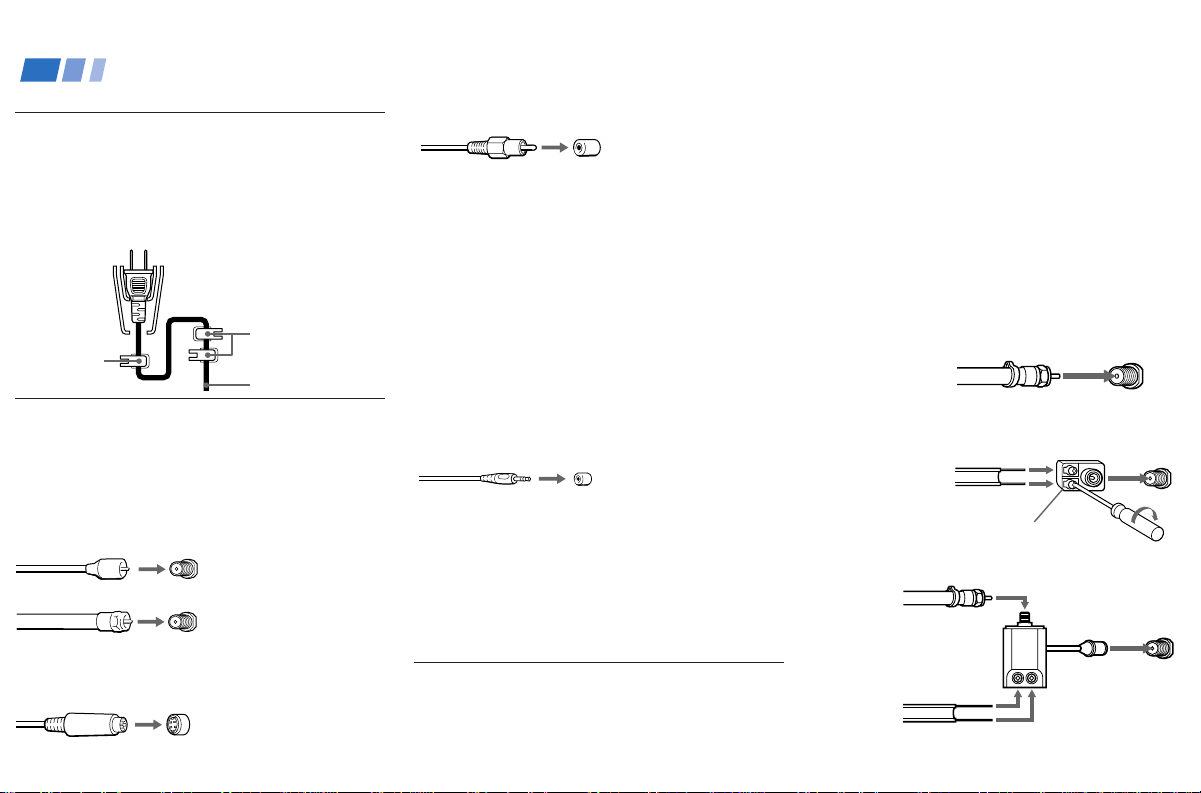
Note on AC Power Cord
The AC power cord is attached to the rear of
the TV with hooks. Do not attempt to remove
the cord from these hooks. Doing so could
cause damage to the TV.
You can
detach the
cord from
this hook
Do not remove
the cord from
these hooks.
AC Power cord
Connector Types
You may find it necessary to use some of the
following connector types during set up.
Coaxial cable
Standard TV cable and antenna connector
Plug Type
Press onto connection
Screw-on Type
Screw onto connection
S Video cable
High quality video connector for enhanced
picture quality
2
Align guides and
press onto connection
Audio/Video cable
Press onto connection
Video - Yellow
(Some DVD Players are equipped with the
following three video connectors.)
Y - Green
B–Y (Cb) - Blue
R–Y (Cr) - Red
Audio (Left) - White
Audio (Right) - Red
S-Link/CONTROL S cable
Sony connector for S-Link and CONTROL S
connections. These features are exclusive to
Sony products, and allow greater control of all
Sony equipment.
Press onto connection
Note:
• For S-Link and CONTROL S connections,
you can use the combined S-Link/
CONTROL S cable provided with some
Sony video equipment, or you can purchase
a separate S-Link/CONTROL S cable (RKG69HG).
Making Connections
For the best picture quality, a cable TV system
or outdoor antenna is recommended.
Connecting directly to cable or an
antenna
The connection you choose will depend on the
cable found in your home. Newer homes will
be equipped with standard coaxial cable (see
A); older homes will probably have 300-ohm
twin lead cable (see
contain both (see
A • VHF only
or
• VHF/UHF
or
• Cable
B • VHF only
or
• UHF only
or
• VHF/UHF
75-ohm coaxial cable
C • VHF
and
• UHF
300-ohm twin lead cable
B); still other homes may
C).
75-ohm
coaxial cable
300-ohm twin
lead cable
Antenna connector
(Rear of TV)
VHF/UHF
(Rear of TV)
VHF/UHF
(Rear of TV)
VHF/UHF
EAC-66 U/V mixer
(not supplied)

Cable or antenna
Most simple connection. Connection is made
directly from the cable or antenna to the TV.
(Rear of TV)
Cable
VHF/UHF
Cable and antenna
You may find it convenient to use the
following set up if your cable provider does
not feature local channels that you are able to
receive using an antenna.
(Rear of TV)
CATV cable
(No connection "TO
CONVERTER" in this case)
Antenna cable
Select Cable or ANT mode by pressing ANT on
the remote control.
AUX
TO CONVERTER
VHF/UHF
Connecting a cable box
Some pay cable TV systems use scrambled or
encoded signals that require a cable box* to
view all channels.
(Rear of TV)
Cable
OUTIN
*Cable box
VHF/UHF
Note:
• If you will be controlling all channel
selection through your cable box, you
should consider using the CHANNEL FIX
feature. (see “CHANNEL SET UP” on
page 26)
Cable box and cable
Some pay cable TV systems use scrambled or
encoded signals requiring a cable box* only for
certain channels (e.g. HBO, SHOWTIME, etc.).
*Cable box
scrambled
channels
75-ohm coaxial
cable (not supplied)
CATV cable
(unscrambled channels)
(Rear of TV)
AUX
TO CONVERTER
(signal)
VHF/UHF
For this set up, you can switch between scrambled
channels (through your cable box), and normal
(CATV) channels by pressing ANT on your
remote control.
Notes:
• You may be able to program your Sony
remote control to operate your cable box.
(see “Operating a Cable Box or DBS
Receiver” on page 34)
• During PIP, P&P, CHANNEL INDEX or
FAVORITE CHANNEL viewing, the AUX
input can only be viewed in the main picture.
• If you are connecting a cable box through the
AUX input and would like to switch between
the AUX and normal (CATV) input you
should consider using CHANNEL FIX.
(see “CHANNEL SET UP” on page 26)
3
Connecting and Installing the TV (continued)
Connecting an antenna/cable TV
system with a VCR
1 Attach the coaxial connector from your
cable or antenna to IN on your VCR.
2 Using AUDIO/VIDEO connectors, connect
AUDIO and VIDEO OUT on your VCR to
AUDIO and VIDEO IN on your TV
(Yellow-VIDEO, White-AUDIO Left, RedAUDIO Right).
3 Using a coaxial connector, connect OUT on
your VCR to VHF/UHF on your TV.
Disconnect all power sources before making any connections.
(Rear of TV)
AUX
TO
3
Coaxial cable
VCR
OUT
Cable
1
LINE
IN
OUT
AUDIO R AUDIO L VIDEO
S VIDEO
CONVERTER
VHF/UHF
S VIDEO
VIDEO
(
MONO
AUDIO
L
)
R
VIDEO IN
134
Y
B–Y
R–Y
L
AUDIO
R
S- LINK
CONTROL S
OUT
AUDIO-R (red)
AUDIO-L (white)
VIDEO (yellow)
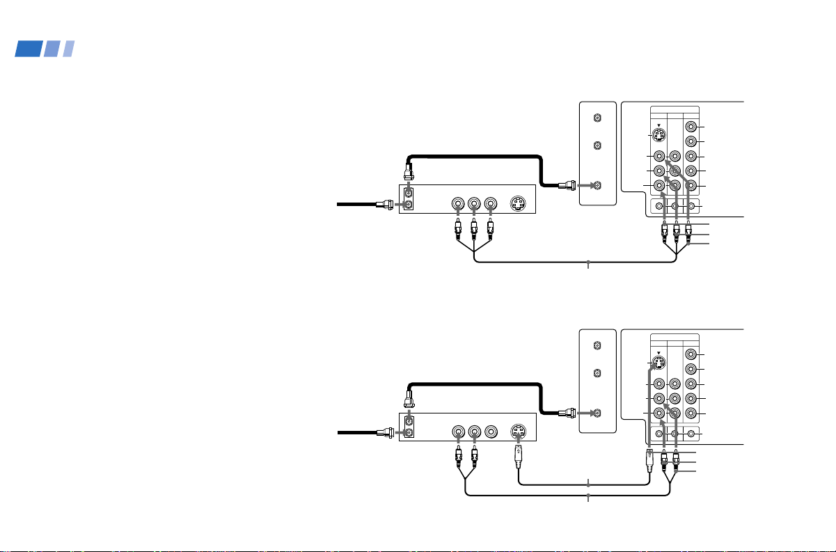
Connecting to an S Video equipped
VCR
1 Attach the coaxial connector from your
cable or antenna to IN on your VCR.
2 Using AUDIO connectors, connect AUDIO
OUT on your VCR to AUDIO IN on your TV
(White-AUDIO Left, Red-AUDIO Right).
3 Using a coaxial connector, connect OUT on
your VCR to VHF/UHF on your TV.
4 Using an S VIDEO connector, connect
S VIDEO on your VCR to S VIDEO on
your TV.
Note:
• If you are connecting a monaural VCR,
connect only the single audio output to the
left (MONO) input on your TV.
4
2
VMC-810S/820S (not supplied)
(Rear of TV)
AUX
TO
3
Coaxial cable
VCR
OUT
Cable
1
LINE
IN
OUT
AUDIO R AUDIO L VIDEO
S VIDEO
4
2
CONVERTER
VHF/UHF
YC-15V/30V
(not supplied)
RK-74A (not supplied)
S VIDEO
VIDEO
(
MONO
AUDIO
L
)
R
VIDEO IN
134
Y
B–Y
R–Y
L
AUDIO
R
S- LINK
CONTROL S
OUT
S VIDEO
AUDIO-R (red)
AUDIO-L (white)
VIDEO IN
134
L
R
(
MONO
)
VIDEO
S VIDEO
OUT
AUDIO
L
R
Y
B–Y
R–Y
AUDIO
S- LINK
CONTROL S
AUX
TO
CONVERTER
VHF/UHF
AUDIO R AUDIO L VIDEO
S VIDEO
LINE
OUT
OUT
IN
OUT
IN
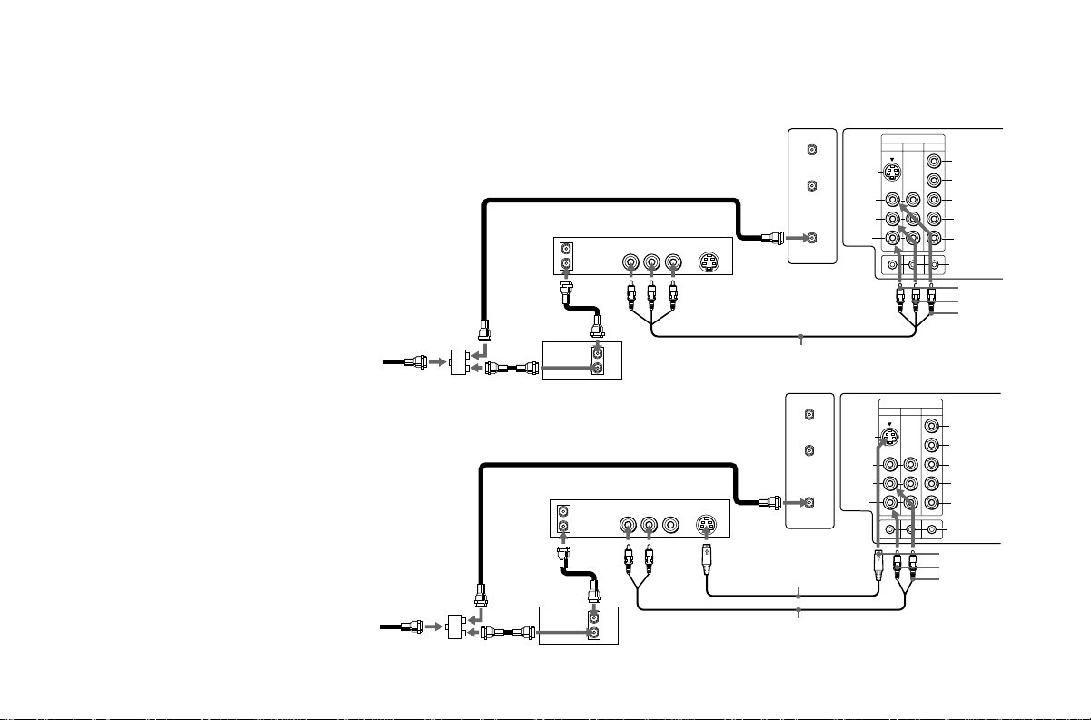
Connecting a VCR and TV with a
cable box
1 Connect the single (input) jack of the
Splitter to your incoming cable connection,
and connect the other two (output) jacks
(using coaxial cable) to IN on your cable
box and VHF/UHF on your TV.
2 Using a coaxial connector, connect OUT
on your cable box to IN on your VCR.
3 Using AUDIO/VIDEO connectors,
connect AUDIO and VIDEO OUT on your
VCR to AUDIO and VIDEO IN on your
TV (Yellow-VIDEO, White-AUDIO Left,
Red-AUDIO Right).
Connecting to an S Video equipped
VCR with a cable box
1-2 Perform as described above.
3 Using AUDIO connectors, connect AUDIO
OUT on your VCR to AUDIO IN on your TV
(White-AUDIO Left, Red-AUDIO Right).
4
Using an S VIDEO connector, connect S
VIDEO on your VCR to S VIDEO on your TV.
Note:
• To view scrambled channels through your
cable box, select the video input which
your cable box is connected to by pressing
TV/VIDEO.
Cable
(not supplied)
Cable
Splitter
(not supplied)
Disconnect all power sources before making any connections.
(Rear of TV)
Coaxial cable
VCR
AUDIO-R (red)
AUDIO-L (white)
VIDEO (yellow)
Y
B–Y
R–Y
L
AUDIO
R
S- LINK
CONTROL S
OUT
S VIDEO
AUDIO-R (red)
AUDIO-L (white)
2
Cable boxSplitter
Coaxial cable
2
OUT
IN
VCR
AUDIO R AUDIO L VIDEO
LINE
OUT
OUT
3
IN
3
VMC-810S/820S (not supplied)
(Rear of TV)
S VIDEO
4
AUX
TO
CONVERTER
VHF/UHF
YC-15V/30V
(not supplied)
S VIDEO
VIDEO
(
MONO
AUDIO
L
)
R
VIDEO IN
134
RK-74A (not supplied)
1
1
Cable box
5
VIDEO IN
134
L
R
(
MONO
)
VIDEO
S VIDEO
OUT
AUDIO
L
R
Y
B–Y
R–Y
AUDIO
S- LINK
CONTROL S
AUX
TO
CONVERTER
VHF/UHF
AUDIO R AUDIO L VIDEO
AUDIO R AUDIO L VIDEO
SATELLITE IN
VHF/UHF
S VIDEO
OUT
IN
LINE OUT
LINE IN
VHF/UHF
S VIDEO
OUT
IN
LINE OUT
Connecting and Installing the TV (continued)
Connecting a DBS (Direct Broadcast
Satellite) receiver
1 Connect the cable from your satellite antenna
to your DBS receiver.
2 Attach the coaxial connector from your cable or
antenna to VHF/UHF on your TV.
3 Using AUDIO/VIDEO connectors, connect
AUDIO and VIDEO OUT on your DBS receiver
to AUDIO and VIDEO IN on your TV.
Connecting a DBS (Direct Broadcast
Satellite) receiver and a VCR
1 Connect the cable from your satellite antenna
to your DBS receiver.
2 Attach the coaxial connector from your cable or
antenna to VHF/UHF-IN on your VCR.
3 Using a coaxial connector, connect VHF/UHF-
OUT on your VCR to VHF/UHF on your TV.
4
Using AUDIO/VIDEO connectors, connect
AUDIO and VIDEO OUT on your DBS receiver to
AUDIO and VIDEO IN on your VCR.
5 Using AUDIO/VIDEO connectors, connect
AUDIO and VIDEO OUT on your VCR to
AUDIO and VIDEO IN on your TV.
Note:
• To view input from the DBS or VCR, select
the video input which your DBS receiver or
VCR is connected to by pressing TV/VIDEO
on the remote control.
6
Disconnect all power sources before making any connections.
(Rear of TV)
1
1
Satellite
antenna
cable
DBS receiver
SATELLITE IN
AUDIO R AUDIO L VIDEO
LINE OUT
3
VMC-810S/820S (not supplied)
4
AUX
TO
CONVERTER
VHF/UHF
S VIDEO
VHF/UHF
2
IN
OUT
VMC-810S/820S (not supplied)
S VIDEO
VIDEO
(
MONO
AUDIO
134
L
)
R
VIDEO IN
Y
B–Y
R–Y
L
AUDIO
R
S- LINK
CONTROL S
OUT
AUDIO-R (red)
AUDIO-L (white)
VIDEO (yellow)
(Rear of TV)
2
VCR
3
5
VMC-810S/820S (not supplied)
DBS receiver
VIDEO (yellow)
AUDIO-L (white)
AUDIO-R (red)
OUT
MONITOR
AUDIO
(
VAR/FIX
)
TV
VIDEO IN
134
IN
L
R
(
MONO
)
VIDEO VIDEO
S VIDEO
OUT
AUDIO
L
R
(
MONO
)
AUDIO
L
R
Y
B–Y
R–Y
AUDIO
S- LINK
CONTROL S
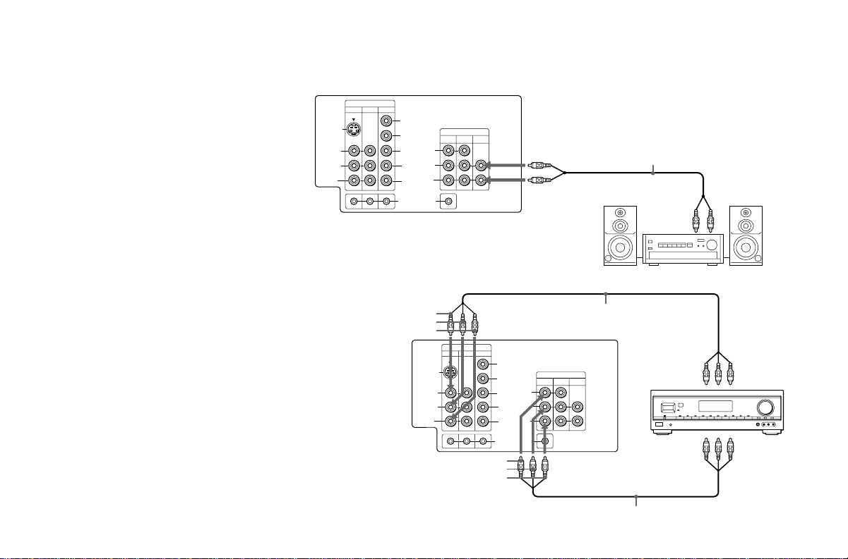
Connecting an audio system
For more dynamic sound, connect your audio
system to your TV.
1
Using AUDIO connectors, connect AUDIO
OUT on your TV to one of the unused Line
inputs (e.g. Tape-2, AUX1, etc.) on your stereo
(White-AUDIO Left, Red-AUDIO Right).
2 Set your stereo to the chosen Line input
and use the AUDIO menu to set your
audio output. (see “SPEAKER” and
“AUDIO OUT” on page 24)
(Rear of TV)
VIDEO IN
134
S VIDEO
VIDEO VIDEO
L
(
)
MONO
AUDIO
R
Y
B–Y
R–Y
L
AUDIO
R
S- LINK
CONTROL S
OUT
(
MONO
AUDIO
Disconnect all power sources before making any connections.
OUT
AUDIO
MONITOR
TV
(
)
VAR/FIX
AUDIO-L (white)
L
)
R
IN
AUDIO-R (red)
2
RK-74A
(not supplied)
Line
input
1
HRD
Connecting an AV receiver
For greater control of all audio and video
equipment, connect your AV receiver.
1 Using AUDIO/VIDEO connectors, connect
VIDEO 1 IN on your TV to Monitor AUDIO
and VIDEO OUT on your AV receiver.
2 Using AUDIO/VIDEO connectors, connect
TV OUT on your TV to TV AUDIO and
VIDEO IN on your AV receiver.
Note:
• You may want to use CHANNEL FIX to
fix your TV's input to the AV receiver
(VIDEO 1). (see “CHANNEL SET UP” on
page 26)
VIDEO (yellow)
AUDIO-L (white)
AUDIO-R (red)
AUDIO-L (white)
VIDEO (yellow)
AUDIO-R (red)
VMC-810S/820S (not supplied)
(Rear of TV)
AV receiver
VMC-810S/820S (not supplied)
1
AV outputs
2
AV inputs
7
Connecting and Installing the TV (continued)
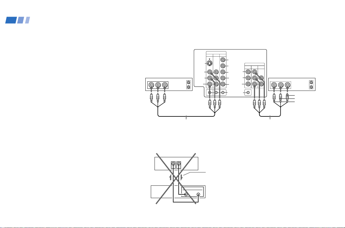
Connecting two VCRs for tape
editing using MONITOR OUT
MONITOR OUT gives you the ability to use a
second VCR to record a program being played
by the primary VCR or to perform tape
editing and dubbing.
1 Connect the VCR intended for playback
using the connection instructions on page
4 of this manual.
2 Using AUDIO/VIDEO connectors,
connect AUDIO and VIDEO IN on your
VCR intended for recording to MONITOR
AUDIO and VIDEO OUT on your TV.
Notes:
• Do not change the input signal while
editing through MONITOR OUT.
• When connecting a single VCR to the TV;
if VCR LINE OUT is connected to TV
VIDEO IN, do not connect the TV
MONITOR OUT jacks to the VCR LINE
INPUT (see right). Doing so will cause
program interference and other viewing
problems.
Disconnect all power sources before making any connections.
(Rear of TV)
VIDEO IN
134
S VIDEO
VCR (for playback)
AUDIO R AUDIO L VIDEO AUDIO R AUDIO L VIDEO
LINE
OUT
VIDEO VIDEO
L
(
)
MONO
AUDIO
OUT
IN
R
1
Y
B–Y
R–Y
L
AUDIO
R
S- LINK
CONTROL S
OUT
(
MONO
AUDIO
OUT
AUDIO
MONITOR
TV
(
)
VAR/FIX
L
)
R
IN
VCR (for recording)
2
VMC-810S/820S (not supplied)
(Rear of TV)
VIDEO IN
VCR
MONITOR
OUT
LINE
IN
Indicates direction
of signal
OUT
VMC-810S/820S (not supplied)
OUT
LINE
IN
IN
VIDEO (yellow)
AUDIO-L (white)
AUDIO-R (red)
8
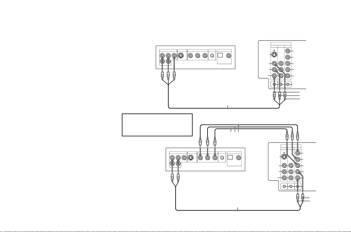
Connecting a DVD Player (Upper
illustration)
Using AUDIO/VIDEO connectors, connect
VIDEO 1 IN on your TV to LINE OUT on
your DVD Player.
Connecting a DVD Player with
component video output
connectors (Lower illustration)
1 Using AUDIO connectors, connect AUDIO
R and L of the LINE OUT on your DVD
Player to AUDIO R and L on the VIDEO IN
4 panel at the rear of your TV.
2 Using three yellow VIDEO connectors,
connect Y, B–Y, and R–Y on the
COMPONENT VIDEO OUT on your DVD
Player to Y, B–Y, and R–Y on the VIDEO
IN 4 panel at the rear of your TV.
Notes:
• Some DVD Player terminals may be
labeled Y, Cb, and Cr. If so, connect Y
(green) to Y, B-Y (blue) to Cb, and R-Y
(red) to Cr.
• Since the high quality pictures on a DVD
disc contain a lot of information, picture
noise may appear. In this case, adjust the
SHARPNESS in the VIDEO menu. (see
SHARPNESS on page 23)
DVD
LINE OUT
S VIDEO OUT
R–AUDIO 1–L VIDEO
COMPONENT VIDEO OUT
Connect your DVD Player directly to
your TV. Connecting the DVD Player
through other video equipment will
cause unwanted picture noise.
DVD
LINE OUT
S VIDEO OUT
R–AUDIO 1–L VIDEO
Disconnect all power sources before making any connections.
(Rear of TV)
VIDEO IN
S-LINK
OPTICAL COAXIAL
R-YY B-Y
VMC-810S/820S
(not supplied)
COMPONENT VIDEO OUT
S-LINK
R-YY B-Y
DIGITAL OUT
VMC-10HG (not supplied)
DIGITAL OUT
OPTICAL COAXIAL
RK-74A
(not supplied)
S VIDEO
VIDEO
(
MONO
AUDIO
L
)
R
S VIDEO
VIDEO
(
134
VIDEO IN
134
L
)
MONO
AUDIO
R
Y
B–Y
R–Y
L
AUDIO
R
S- LINK
CONTROL S
OUT
AUDIO-R (red)
AUDIO-L (white)
VIDEO (yellow)
(Rear of TV)
Y
B–Y
R–Y
L
AUDIO
R
S- LINK
CONTROL S
OUT
AUDIO-L (white)
AUDIO-R (red)
9

Connecting and Installing the TV (continued)
Connecting a camcorder
Use this connection to view a picture directly
from your camcorder.
Using AUDIO/VIDEO connectors, connect
AUDIO and VIDEO OUT on your camcorder
to AUDIO and VIDEO IN on the front panel
of your TV (Yellow-VIDEO, White-AUDIO
Left, Red-AUDIO Right).
Notes:
• If you are connecting a monaural
camcorder, connect only the single audio
output to the left (MONO) input on your
TV.
• If you have an S Video equipped
camcorder, you can use an S Video
connection.
Disconnect all power sources before making any connections.
VIDEO
2
IN
S VIDEO
VIDEO
L
(MONO)
AUDIO
R
AV output
VIDEO (yellow)
AUDIO-L (white)
AUDIO-R (red)
VMC-810S/820S
(not supplied)
10
 Loading...