

Sony Trinitron KV-32XBR37, Trinitron KV-27XBR37M, Trinitron KV-27XBR37 Operating Instructions Manual
Trinitron °Color TV
Operating Instructions
KV-2 7XBR37
KV-27XBR37M
KV-32XBR37
@1994 by Sony Corporation
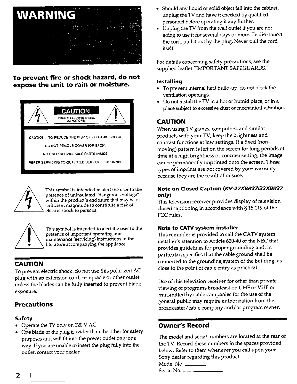
To prevent fire or shock hazard, do not
expose the unit to rain or moisture.
CAUTION : TO REDUCE THE RISK OF ELECTRIC SHOCK_
DO NOT REMOVE COVER {OR BACK}.
NO USER.SERVICF=A_ILE PARTS {NSt0E.
REFER SERV{CING TO QUALIF[ED S_RVICE PERSONNEL,
_ h.is symbol is intended to alert the user to the
presence of uninsulated "dangerous voltage"
within the product's enclosure that may be of
sufficient magnitude to constitute a risk of
electric shock to persons.
This symbol is intended to alert the user to the
presence of important operating and
maintenance (servicing) instructions in the
literaVare accompanying the appliance.
II
CAUTION
To prevent electric shock, do not use this polarized AC
plug with an extension cord, receptacle or other outlet
unless the blades can be fully inserted to prevent blade
exposure.
Precautions
Safety
• Operate the TV only on 120 V AC.
• One blade of the plug is wider than the other for safety
purposes and will fit into the power outlet only one
way. If you are unable to insert the plug hilly into the
outlet, contact your dealer.
2 !
* Should any liquid or solid object fail into the cabinet,
unplug the TV and have it checked by qualified
persormel before operating it any further.
• Unplug the TV from the wall outlet if you are not
going to use it for severn days or more. To disconnect
the cord, pull it out by Lheplug. Never pull the cord
i_elL
]Fordetails concerning safety precautions, see the
supplied leaflet "IMPORTANT SAFEGUARDS."
Installing
• To prevent internal heat build-up, do not bleak the
ventilation openings.
• Do not install the TV in a hot or humid place, or in a
place subject to excessive dust or mechanical vibration.
CAUTION
When using TV games, computers, and similar
products with your TV, keep the brightness and
contrast fund:ions at low settings. If a fixed (non-
moving) pattern is left on the screen for long periods of
time at a high brightness or contrast setting, the image
can be permanently imprinted onto the screen. These
types of imprints are not covered by your warranty
because they are the result of misuse.
Note on Closed Caption (KV-27XBR37/32XBR37
only)
This television receiver provides display of television
closed captioning in accordance with § 15.119 of the
FCC rules.
Note to CATV system installer
This reminder is provided to call the CATV system
installer's attention to Article 820-40 of the NEC that
provides guidelines for proper grounding and, in
particular, specifies that the cabIe gromnd shall be
connected to the grounding system of the building, as
close to the point of cable entry as practical.
Use of this television receiver for other than private
viewing of programs broadcast on UHF or VHF or
transmitted by cable companies for the use of the
general pubUc may require authorization from the
broadcaster/cable company and/or program owner.
II
Owner's Record
The model and seria! numbers are located at the rear of
the TV, Record these numbers in the spaces provided
below. Refer to them whenever you call upon your
Sony dealer regarding this product.
Model No.
Serial No..
4 Welcome!
4 About thismanual
I
Getting Started
5 Step 1: Connections
11 Step 2: Setting up the remote commander
12 Step 3: Setting cable TV on or off
13 Step 4: Presetting channels
Operations
15 Watching theTV
17 Watching two programs at the same time--PIP
18 Adiusting the picture (VIDEO)
19 Adjusting the sound (AUDIO)
20 Listening to surround sound (SURROUND)
21 Selecting stereo or bilL_gual programs (Mrs)
21 Setting the speakers(SPEAKER)
22 Selecting audio out (AUDIO OUT)
22 Listening to orchestra seat effect sound--OSE
23 Listening with the cordless headphones
(HEADPHONES)
25 Setting the clock (CURRENT TIME SET)
26 Setting the timer to turn the TV on and off (ON/On:
ER)
27 Blocking out a channel (CHANNEL BLOCK)
28 Customizing the channel number buttons (CH
CAPTION/GUIDE)
29 Setting video labels (VIDEO LABEL)
30 Displaying closed caption (¢LOSEDCArmON)
31 Operating video equipment
33 Operating a cable box
I
Additional Information
35 Troubleshooting
37 Specifications
38 Index
The captions in parentheses indicate menu names.
Thank you for purchasing the Sony Trinitron _ Color
TV. Here are some of the features you will enjoy with
your TV:
• On-screen menus let you adjust the picture quality,
sound, and various other settings.
• Surround system simulates the sound quality of a
concert hall or movie theater.
• Two-_ner picture-in-picture allows you to watch
another TV channel, video or cable image as a window
picture.
• Orchestra Seat Effect (OSE) feature restores the
harmonic balance of the sound to dramatically
improve the overall reproduction of programs. It gives
the sound more clarity, depth, and definition, making
the sound more dynamic.
• IR transmitter allows you to listen to a TV program
with the cordless headphones.
• With the supplied Remote Commander you can
operate the TV. In addition, you can operate Sony
video and Sony multi-disc players. Other
manufacturer's video equipment might also be
compatible with thi_ remote commander.
• Center speaker allows you to enjoy the benefits of
Dolby Pro Logic by using the speakers of the TV as the
ce.nter speaker.
The instructions in this manua! are for models
KV-27XBR37, KV-27XBR37M, and KV-32XBR37. Before
you start reading this manual please check your model
number which is displayed on the rear of the TV.
Model KV-27XBR37 is used for illustration purposes in
this manual. Any exceptions in operations between
models are clearly indicated in the text. For example,
"KV-27XBR37 only."
The following instructions describe operation based on
using the remote commander buttons. Basic functions
can also be performed by using buttons on the TV.
&
Getting Started
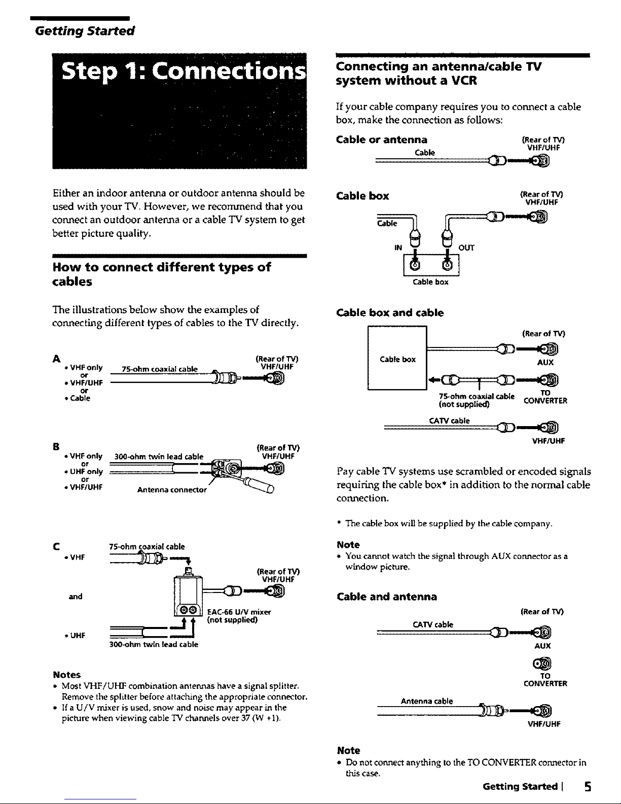
Either an indoor antenna or outdoor antenna should be
used with your TV, However, we recommend that you
connect an outdoor antenna or a cable TV system to get
better picture quality.
How to connect different types of
cables
The illustrations below show the examples of
connecting different types of cables to the TV directly.
A (_earof'r_
• VHF only 75-ohm coaxial cable VHF/UHF
• VHF!UHF
or
,,Cable
- VHF only
or
• UHF only
or
• VHF/UHF
(Rear of TV)
30(]_ohm twin lead cable VHFIUHF
75-ohm coaxial cable
• VHF _ ,,=._
(Rear of TV)
EACh66 U/V mixer
. UHF l t I (not supplied)
300-ohm twin read cable
Notes
• Most VHF/UHF combination antennas have a signal splitter.
Remove the splitter before attaching the appropriate connector.
• If a U/V mixer is used, snow and noise may appear in the
picture when viewing cable TV channels over 37 (W +1).
[ I _ I II II _ I
Connecting an antenna/cable TV
system without a VCR
If your cable company requires you to connect a cable
box, make the connection as foUows:
Cable or antenna (RearofTV)
VHF/UHF
Cable box
IN I
(Rear of/V)
VHF/UHF
Cable box
Cable box and cable
Cable box
(RearofTV)
AUX
75-ohm coaxial cable TO
(not supplied) CONVERTER
CATV cable
VHFIUHF
Pay cable TV systems use scrambled or encoded signals
requiring the cable box* in addition to the normal cable
connection.
* The cable box will be supplied by the cable company.
Note
e You cannot watch the signal through AUX connector as a
window picture.
Cable and antenna
CATV cable
Antenna cable
(Rear of TV)
AUX
TO
CONVERTER
VHF/UHF
Note
* Do notconnect anything tothe TOCONVERTERconnectorin
this case.
Getting Started I 5
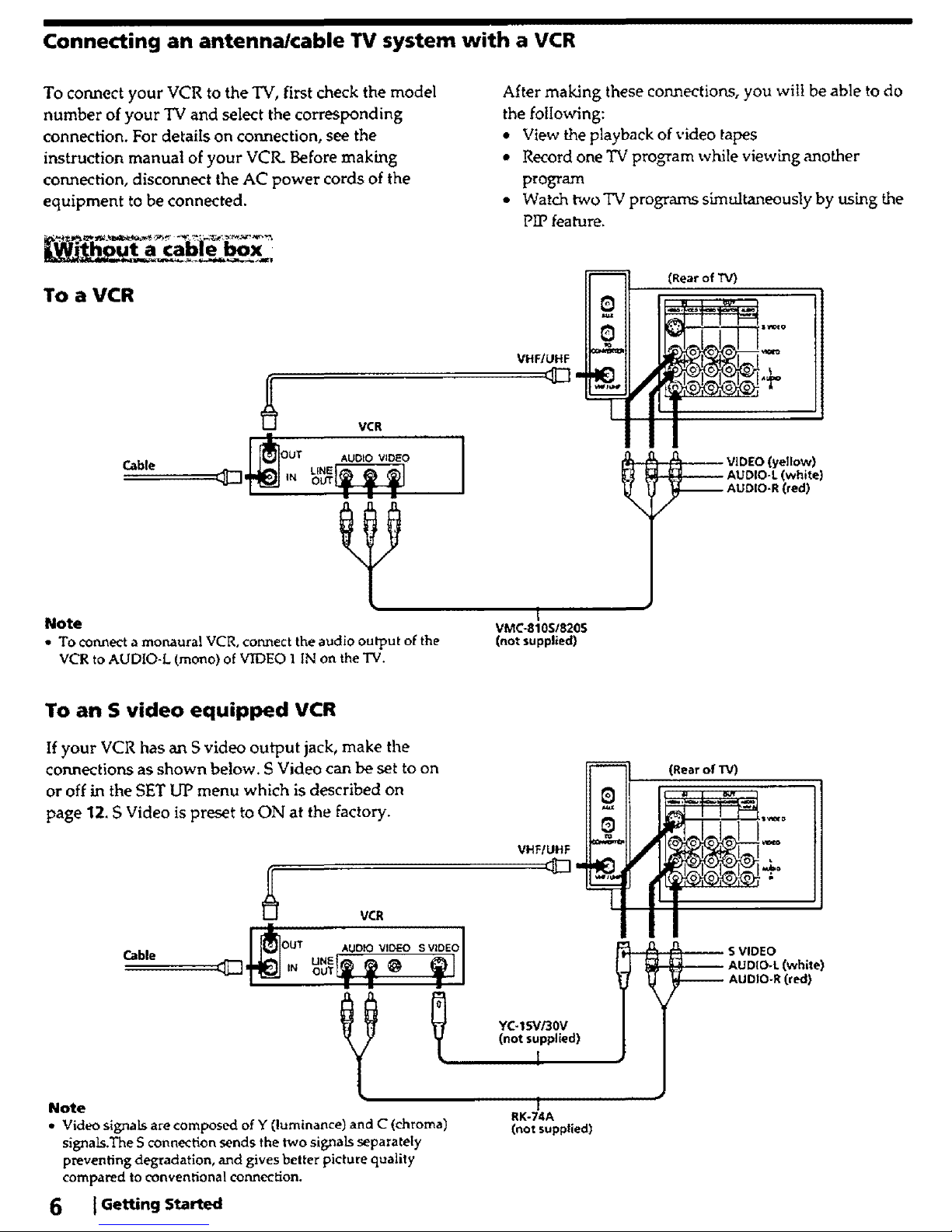
Connecting an antenna/cable TV system with a VCR
To connect your VCR to the TV, first check the model
number of your TV and select the corresponding
connection. For details on connection, see the
instruction manual of your VCIL Before making
connection, disconnect the AC power cords of the
equipment to be connected.
To a VCR
After making these connections, you will be able to do
the following:
• View the playback of video tapes
• Record one TV program while viewkng another
program
• Watch two TV programs simultaneously by ush_g the
PIP feature.
Cable
VCR
I_OUT AUDIO VIDEO
Note
• To connect a monaural VCR, connect the audio output of the
VCR to AUDIO-L (mono) of VIDEO 1 IN on the TV.
VHF/UHF
t
VMC-810SI8205
(not supplied)
(Rear of TV)
"_ ; _ VIDEO (yellow)
_ AUDIO-L (white)
_ AUDIO-R (red)
To an S video equipped VCR
If your VCR has an S video output jack, make the
connections as shown below. S Video can be set to on
or off in the SET UP menu which is described on
page 12. S Video is preset to ON at the factory.
Cable
VCR
AuD sv,o,ol
YC-15Vi30V
(not supplied)
I
Note
• Video signals are composed of Y (luminance) and C (chroma)
signaLs.The S connection sends the two signals separately
preventing degradation, and gives better picture quality
compared to conventional connection.
6 tGettingStarted
1
RK-74A
(not supplied)
(RearofTV)
_O_ S VIDEO
AUDIO-L (white)
------ AUDIO-R (red)
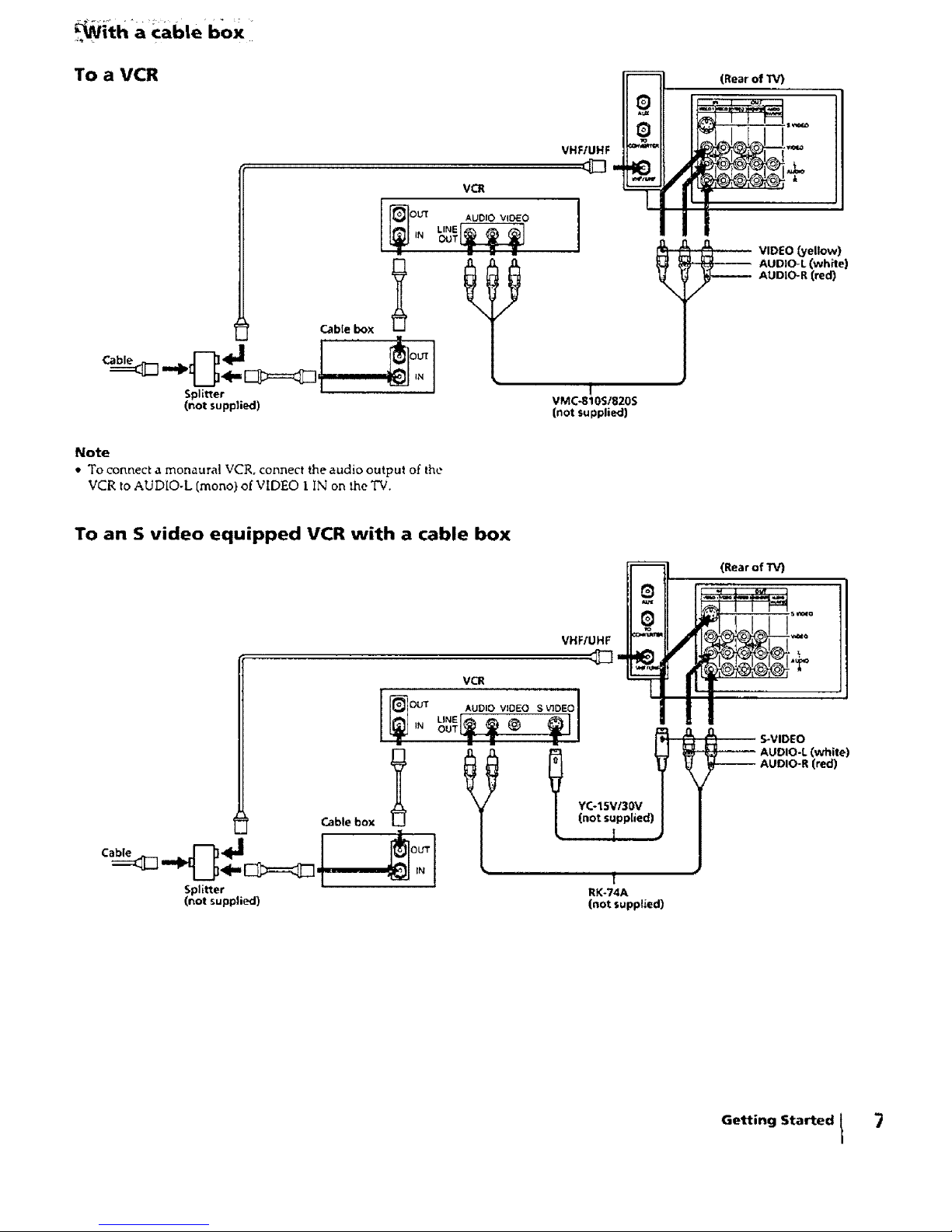
_i_tha cab|e box
To a VCR
VCR
Cable box
Splitter
(not suppEed)
_OU'T AUDI VIDEO
LINE_
iN OUT
IN
VHFfUHF
1
VMC-810S/820S
(not supplied)
(Rear of rV)
VIDEO (yellow)
_ UDIO-L (white)
AUDIO-R (red)
Note
• To connect a monaural VCR, connect the audio output of the
VCR to AUDIO-L (mono) of VIDEO I IN on the TV.
To an S video equipped VCR with a cable box
(RearofTV)
VHF/UHF
,oo,o,,o,o, oEo'
. ___ I i _
YC-15V/30V
Cable box
Splitter RK-74A
(not supplied) (not supplied)
,0, S-VIDEO
-_ UDIO-L (white)
AUDIO-R (red)
Getting Started t
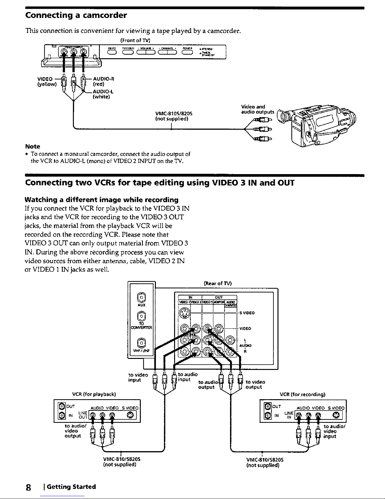
Connecting a camcorder
Thisconnection is convenient for viewing a tape played by a camcorder.
(Front of TVI
N_ (red)
{.yellow)_
,/_,-- AU DIO-I.
(white)
VMC-8105/820S
(not supplied)
1
Note
• To connect a monaural Camcorder, connect the audio output of
the VCR to AUDIO-L (mono) of VIDEO 2 INPUT on the TV.
Video and
audio OUtputs
Connecting two VCRs for tape editing using VIDEO 3 IN and OUT
Watching a different image while recording
If you connect the VCR for playback to the VIDEO 3 IN
jacks and the VCR for recording to the VIDEO 3 OUT
iaeks, the material from the playback VCR will be
recorded on the recordhng VCR. Please note that
VIDEO 30IYI" can only output material from VIDEO 3
IN. During the above recording process you can view
video sources from either antenna, cable, VIDEO 2 IN
or VIDEO 1 IN jacks as well
to video
input
VCR (for playback)
to audio/
video
output
|
VMC-810tS820S
(not supplied)
(Rear of TV)
OUT
S VtOEO
output _ Output
_ input
VCR (for recording)
VMC-810IS820S
(not supplied)
8 [Getting Started
I
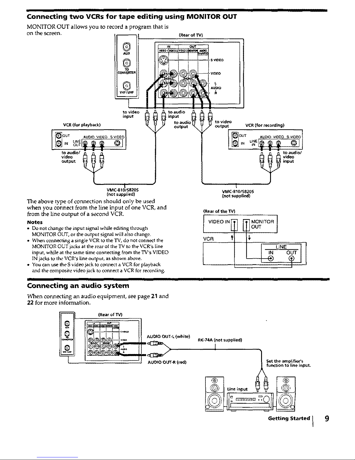
Connecting two VCRs for tape editing using MONITOR OUT
MONITOR OUT allows you to record a program that is
on the screen. (RearofW)
ml
to video
input
VCR (for playback)
uN__ _-'_-_-I I
OuTer
to audio/ __
video
output,
VMC-81_/S;20S
(not supplied)
The above type of connection should only be used
when you connect from the line Lnput of one VCR, and
from the line output of a second VCR.
Notes
• Do not chan_e the input signal while editing through
MONITOR OUT, or the outpu! signal will also change.
• When connecting a single VCR to the TV, do not connect the
MONITOR OUT jacks at the rear of the TV to the VCR's line
input, while at the same time connecting From the TV's VIDEO
IN jacks to the VCR's line output, as shown above.
• You Can use the S v_deo jack to connect a VCR for playback
and the composite video jack to connect a VCR for recording.
to video
output
'" (
VMC-810/S820S
(not supplied)
VCR(for re¢ordlng)
to audlo/
_ video
input
(Rear of the TV)
_lllVIDEO IN
v0R 'I
'_ MONITOR 1
jour
LINE
IN OUT
I
Connecting an audio system
I I
When connecting an audio equipment, see page 21 and
22 for more infom_ation.
m
--L
(Rear of TV)
AUDIO OUT-L (white)
AUDIO O_'r.R (red)
RK-74A (not supplied)
Set the amplifier's
function to llne input,
JL
Getting Started 1 9
I I I I I
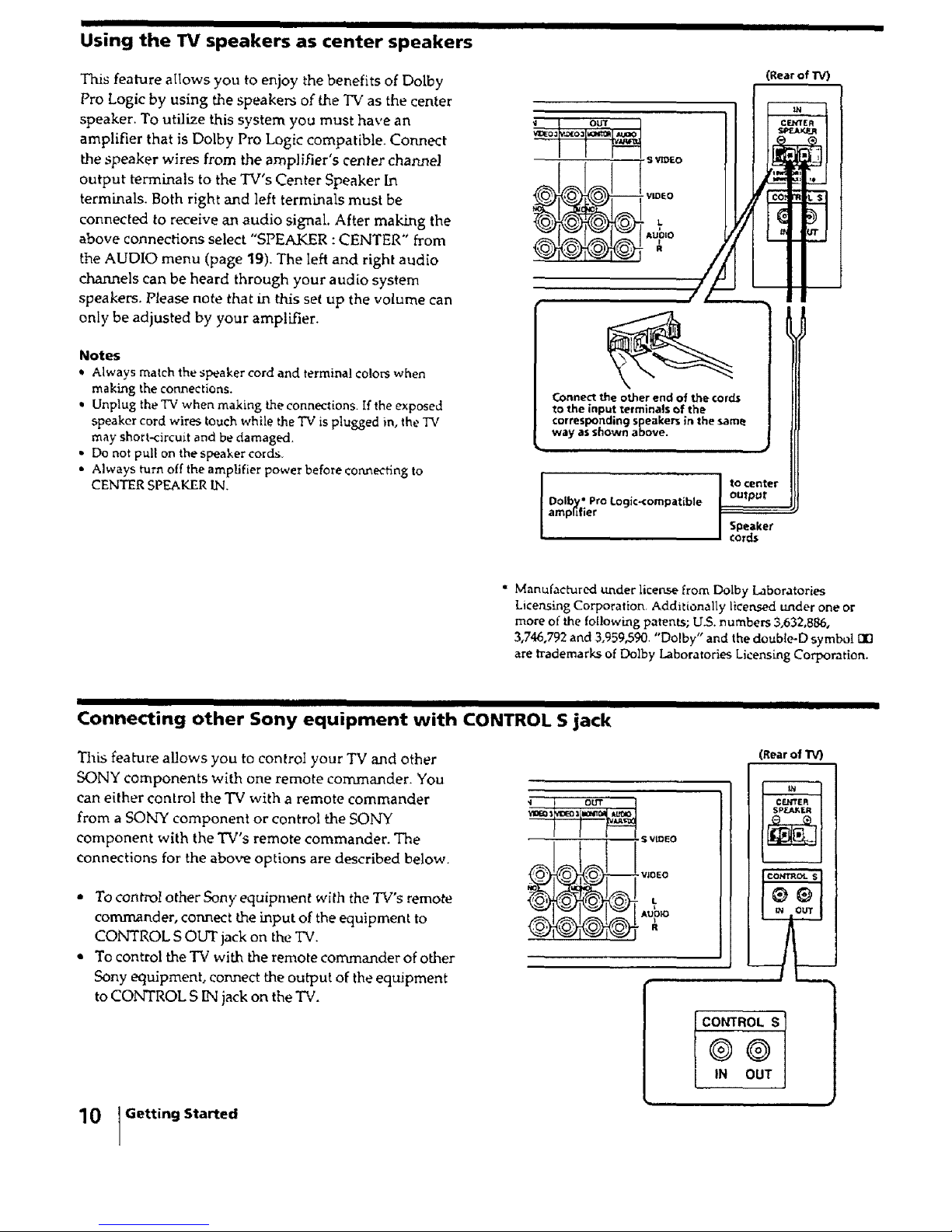
Using the TV speakers as center speakers
This feature alIows you to enjoy the benefits of Dolby
Pro Logic by using the speakers of the TV as the center
speaker. To utilize this system you must have an
amplifier that is Dolby Pro Logic compatible. Connect
the speaker wires from the amplifier's center channel
output terminals to the TV's Center Speaker In
terminals. Both right and left terminals must be
connected to receive an audio signal. After making the
above connections select "SPEAKER :CENTER" from
the AUDIO menu (page 19). The left and right audio
channels can be heard through your audio system
speakers. Please note that in this set up the volume can
only be adjusted by your amplifier.
Notes
Q Always match the speaker cord and termina! colors when
making the connectlons.
Unplug the TV when making the connections. If the exposed
speaker cord wires touch while the TV is plugged in, the TV
may short-circuit and be damaged.
• Do not pull on the speaker cords
• Always turn off the amplifier power before connecting to
CENTER SPEAKER IN.
• L
AUO_O
Connect the other end of the cords
to the input terminals of the
corresponding speakers in the same
way as shown above.
Dolby" Pro Logic_ornpatible
amplifier
(Rear of TV)
to center
output
Speaker
co_ds
" Manufactured under licen-..,_efrom Dolby Laboratories
Licensing Corporation. Additionally licensed under one or
more of the fol!owing patents; U.S. numbers 3,632,886,
3,746,792 and 3,959,590. "Dolby" and the doubled symbol
are trademarks of Dolby Laboratories Licensing Corporation.
II
Connecting other Sony equipment with CONTROL S jack
This feature allows you to control your TV and other
SONY components with one remote commander. You
can either control the TV with a remote commander
from a SONY component or control the SONY
component with the TV's remote commander. The
connections for the above options are described below.
• To control other Sony equipn_ent with the TV's remote
commander, connect the input of the equipment to
CONTROL S OUT jack on the TV.
Q To control the TV with the remote commander of other
Sony equipment, connect the output of the equipment
to CONTROL S IN jack on the "Pv'.
10 Getting Started
- s v_EO
- VIOEO
- L
AUDIO
R
(Rear of TV
CONTROL S I
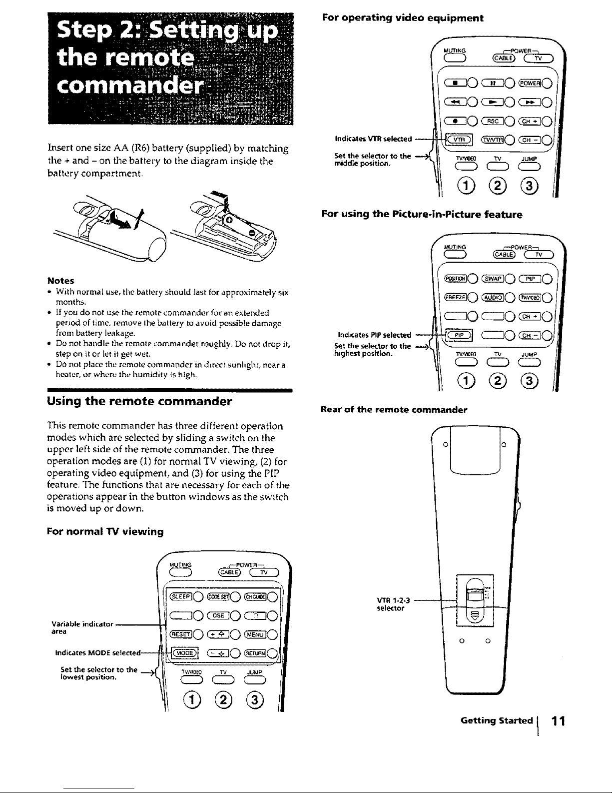
Insert one size AA (R6) battery (supplied) by matching
the + and - on the battery to the diagram inside the
battery compartment.
For operating video equipment
Indicates VTR selected
Set the selector to the --_
middle position.
ciz]O
c cO c so c z]O
cizO c sO
TVMO_O TV ,JUMP
(ED CZD C2D
(9®®
For using the Picture-in-Picture feature
Notes
• With normal use, the battery should last for approximately six
months.
,* If you do not use the remote commander for an extended
period of time, remove the battery to avoid possible damage
from battery leakage.
• Do not handle the remote commander roughly. Do not drop it,
step on it or let it get wet.
• Do not place the remote commander in direct sunlight, near a
healer, Or where the humidity is high,
I II
Using the remote commander
This remote commander has three different operation
modes which are selected by sliding a switch on the
upper left side of the remote commander. The three
operation modes are (1) for normal TV viewing, (2) for
operating video equipment, and (3) for using the PIP
feature. The functions that are necessary for each of the
operations appear in the button windows as the switch
is moved up or down.
For normal TV viewing
Indicates MODE
Set the selector to the _ II
Indicates PIP selected
Set the selector to the
highest position.
Rear of the remote commander
VTR 1-2-3
selector
0 0
Getting Started I
11
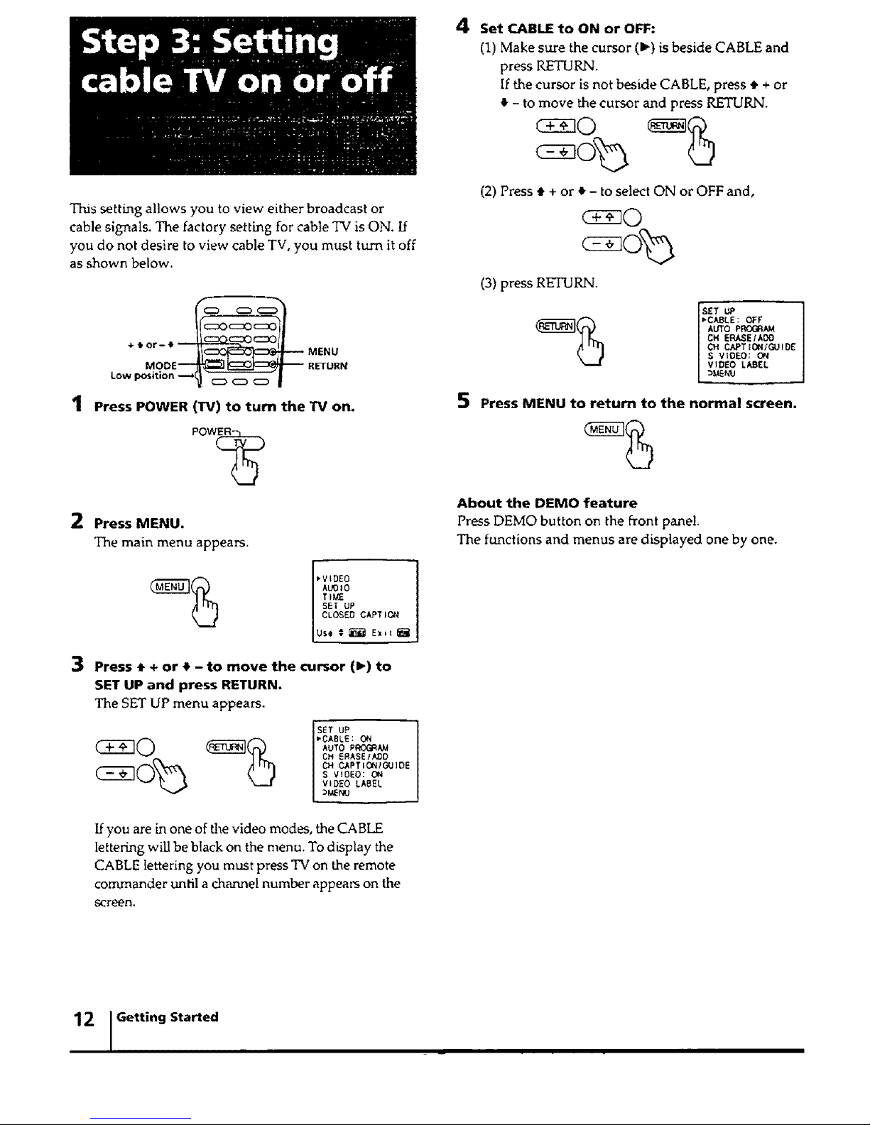
This setting allows you to view either broadcast or
cable signals. The factory setting for cable TV is ON. If
you do not desire to view cable TV, you must turn it off
as shown below.
+,or-e_ MENU
MOOE_ _ RETURN
Press POWER (rff) to turn the TV on.
Pow(_
2 Press MENU.
The main menu appears.
_VIDE0
Alamo
TiME
Use _ _ Exiz _-_
3 Press • + or • - to move the cursor (1_)to
SET UP and press RETURN.
The SET UP menu appears.
SET UP
_CABLE : 061
AUTO PR(X_A_
CH ERASE/N_D
CH CAPT ICLN/GUlOE
S VIOEO: ON
I VIDEO LABEL
If you are in one of the video modes, the CABHZ
lettering will be black on the menu. To display the
CABLE lettering you must press TV on the remote
commander until a channel number appears on the
screen.
4 Set c_,_ to ON or OFF:
(1) Make sure the cursor (1_) is beside CABLE and
press RETURN.
If the cursor is not beside CABLE, press • + or
4 - to move the cursor and press RETURN.
(2) Press • + or • - to select ON or OFF and,
(3) press RETURN.
ScETU,°
ABLE: OFF
AUTO PROGRAM
CH ERASE/AO0
CH CAPT IONIGU IDE
S VIDEO: ON
VIDEO LABEL
5 Press MENU to return to the normal screen.
About the DEMO feature
Press DEMO button on the front pane!.
The functions and menus are displayed one by one.
12 , Getting Started .,
I I
 Loading...