

Sony TRINITRON KV-32FX20A, TRINITRON KV-32FX20D, TRINITRON KV-32FX20B, TRINITRON KV-32FX20E, TRINITRON KV-32FX20U Service Manual
1
SERVICE MANUAL BE-3E CHASSIS
MODEL
COMMANDER DEST CHASSIS NO.
MODEL
COMMANDER DEST CHASSIS NO.
KV-32FX20A
RM-887 Italian SCC-Q22B-A
KV-32FX20B
RM-887 French SCC-Q23B-A
KV-32FX20D
RM-887 AEP SCC-Q21B-A
KV-32FX20E
RM-887 Spanish SCC-Q24B-A
KV-32FX20U
RM-887 UK SCC-Q25B-A
®
MICROFILM
TRINITRON
®
COLOR TV
2
ITEM MODEL Television System Stereo System Channel Coverage Color System
Italian B/G/H GERMAN Stereo
ITALIA VHF : A-H2 (C) UHF : 21-69 PAL
B/G/H VHF : E2-E12 UHF : E21-E69
CABLE TV (1) : S1-S41
CABLE TV (2) : S01-S05,M1-M10,U1-U10
PAL, SECAM
NTSC4.43, NTSC3.58
(VIDEO IN)
French
B/G/H, D/K,L,I GERMAN/NICAM
Stereo
L VHF : F02-F10 UHF : F21-F60
CABLE : B-Q B/G/H VHF : E2-E12
UHF : E21-E69
CABLE TV (1) : S1-S41
CABLE TV (2) : S01-S05, M1-M10, U1-U10
ITALIA VHF : A-H2 (C) UHF : 21-69
I UHF : B21-B69
PAL, SECAM
NTSC4.43, NTSC3.58
(VIDEO IN)
AEP B/G/H GERMAN Stereo
PAL B/G/H/ VHF : E2- E12 : E21-E69
CABLE TV (1) : S1-S41
CABLE TV (2) : S01-S05, M1-M10, U1-U10
ITALIA VHF : A-H2 (C) UHF : 21-69
PAL, SECAM
NTSC4.43, NTSC3.58
(VIDEO IN)
Spanish B/G/H, D/K GERMAN/NICAM
Stereo
PAL B/G/H/ VHF : E2- E12 : E21-E69
CABLE TV (1) : S1-S41
CABLE TV (2) : S01-S05, M1-M10, U1-U10
ITALIA VHF : A-H2 (C) UHF : 21-69
PAL, SECAM
NTSC4.43, NTSC3.58
(VIDEO IN)
UK I NICAM Stereo UHF : B21-B69
PAL
NTSC4.43, NTSC3.58
(VIDEO IN)
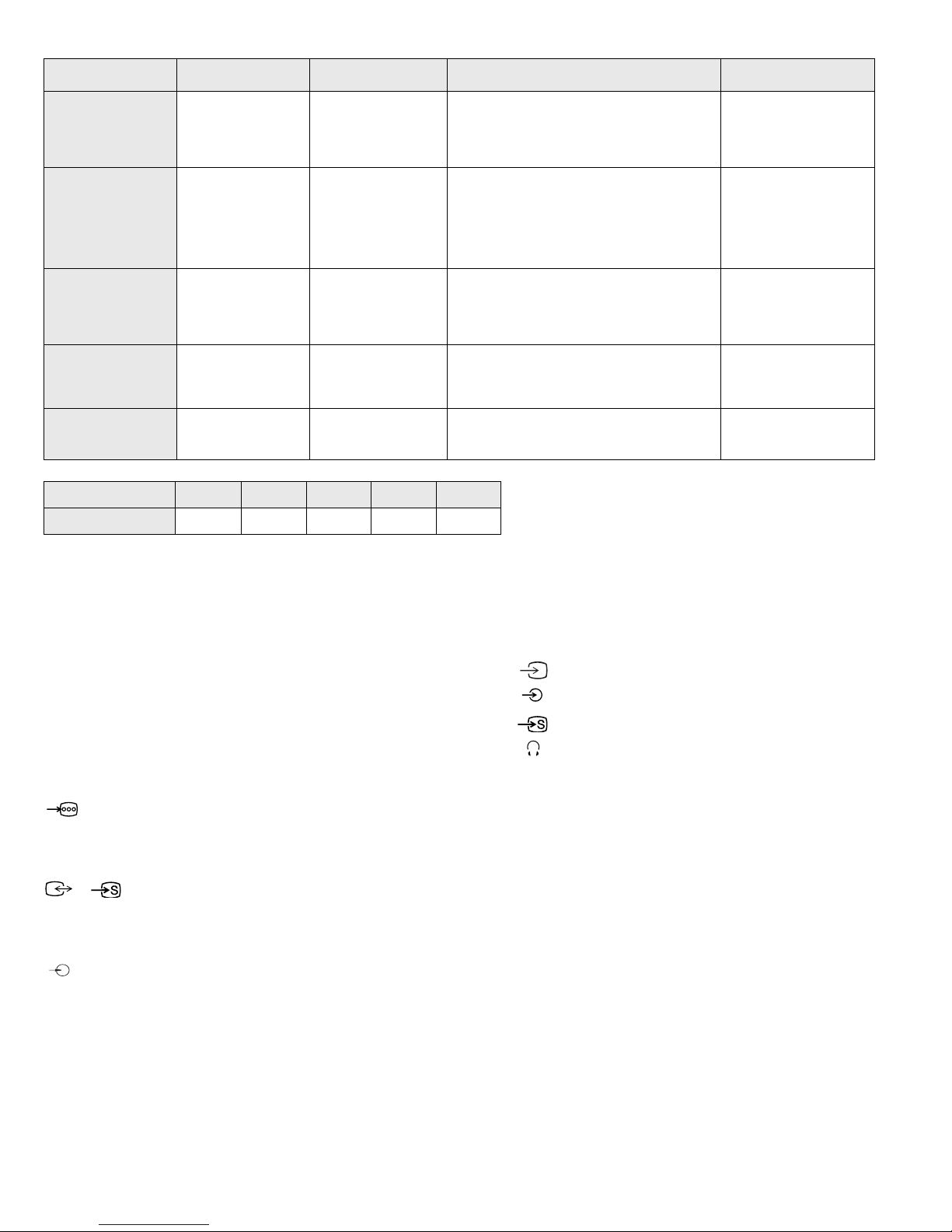
MODEL 32FX20A 32FX20B 32FX20D 32FX20E 32FX20U
Power Consumption 106W 120W 120W 120W 176W
[PICTURE TUBE] FD Trinitron Wide
Approx. 82 cm (32 inches)
(Approx. 76 cm picture measured
diagonally)
102 degree deflection
Input/Output Terminals
[REAR]
1 21-pin Euro connector (CENELEC standard).
- Inputs for Audio and Video signals.
- Inputs for RGB.
- Outputs of TV Video and A ud i o si gn a ls .
2/ 2 21-pin Euro connector
- Inputs for Audio and Video signals.
- Inputs for S video.
- Outputs for Video and Audio signa ls (selectable).
Phono jacks
- Outputs for Audio Signals
[FRONT]
3 Video output - phono jack
3 Audio inputs - p hono jacks
S Video input - 4 pin din
Headphone jack : stereo minijack
Sound output 2x20W (Music Power)
Subwoofer 20W (Music Po wer)
Power requirements 220 - 240V
Dimensions Approx 874x563x571mm (w/h/d)
Weight Approx 62kg
Supplied accessories RM-887 Remote Commander (1)
IEC designated R6 batteries (2)
Other features NICAM*, FASTEXT, TOPTEXT
* (KV-32FX20B, 32FX20E, 32FX20U)
[RM-887]
Remote control system Infrared control
Power requirements 3V dc
2 batteries IEC designation
R6 (size AA)
Dimensions Approx 44x209x23mm (w/h/d)
Weight Approx 89g (Not incl uding battery)
Design and specifications are subject to cha nge without notice.

3
WARNING (KV-32FX20U only)
The flexible m ains lead is supplied connected to a B.S. 136 3 fuse d pl ug
having a fuse of 5 AMP capacity. Should the fuse need to be repla ced,
use a 5 AMP FUSE approved by ASTA to BS 1362, ie one tha t ca rri es the
mark.
IF THE PLUG SUPPLIED WITH THIS APPLIANCE IS NOT SUITABLE
FOR THE OUTLET SOCKETS IN YOUR HOME, IT SHOULD BE CUT
OFF AND AN APPROPRIATE PLUG FITTED. THE PLUG SEVERED
FROM THE MAINS LEAD MUST BE DESTROYED AS A PLUG WITH
BARED WIRES IS DANGEROUS IF ENGAGED IN A LIVE OUTLET
SOCKET.
When an alternati ve type of plug is used it should be fitte d with a 5 AMP
FUSE, otherwise the circuit should be protected by a 5 AMP FUSE at the
distribu tion board.
ASA
T
Model Name
Item
KV-32FX20A KV-32FX20B KV-32FX20D KV-32FX20E KV-32FX20U
Pal Comb OFF OFF OFF OFF OFF
PIP OFF OFF OFF OFF OFF
RGB Priority OFF OFF OFF OFF OFF
Woofer Box ON ON ON ON ON
Scart 1 ON ON ON ON ON
Scart 2 ON ON ON ON ON
Front in (3) ON ON ON ON ON
Scart 4 OFF OFF OFF OFF OFF
Projector OFF OFF OFF OFF OFF
AKB in 16:9 mode ON ON ON ON ON
Norm B/G ON ON ON ON OFF
Norm I OFF ON OFF OFF ON
Norm D/K OFF ON OFF ON OFF
Norm AUS OFF OFF OFF OFF OFF
Norm L OFF ON OFF OFF OFF
Norm SAT OFF OFF OFF OFF OFF
Norm M OFF OFF OFF OFF OFF
Teletext ON ON ON ON ON
Nicam Stereo OFF ON OFF ON ON
Language Preset Italian French German Spanish English
How to replace the fuse.
Open the fuse compartment with
a screwdriver blade and replace
the fuse.
FUSE
4
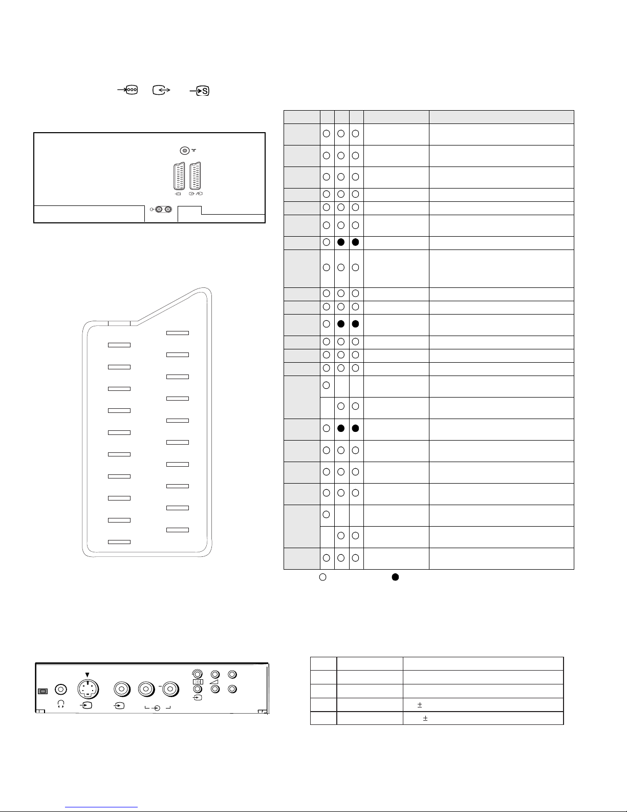
21 pin connector ( 1, 2/ 2)
Connected Not Connected (open) * at 20Hz - 20kHz
19
17
15
13
11
9
7
5
3
1
20
18
16
14
12
10
8
6
4
2
21
Pin No 1 2 4 Signal Signal level
1 Audio output B
(right)
Standard level : 0.5V rms
Output impedence : Less than 1kohm*
2
Audio output B
(right)
Standard level : 0.5V rms
Output impedence : More than 10kohm*
3
Audio output A
(left)
Standard level : 0.5V rms
Output impedence : Less than 1kohm*
4 Ground (audio)
5 Ground (blue)
6 Audio input A
(left)
Standard level : 0.5V rms
Output impedence : More than 10kohm*
7 Blue input 0.7 +/- 3dB, 75 ohms positive
8 Function select
(AV control)
High state (9.5-12V) : Part mode
Low state (0-2V) : TV mode
Input impedence : More than 10K ohms
Input capacitance : Less than 2nF
9 Ground (green)
10 Open
11 Green Green signal : 0.7 +/- 3dB, 75 ohms,
positive
12 Open
13 Ground (red)
14 Ground (blanking)
15
_ _ Red input 0.7 +/- 3dB, 75 ohms, positive
_ (S signal Chroma
input)
0.3 +/- 3dB, 75 ohms, positive
16 Blanking input
(Ys signal)
High state (1-3V) Low state (0-0.4V)
Input impedence : 75 ohms
17 Ground (video
output)
18 Ground (video
input)
19 Video output 1V +/- 3dB, 75ohms, p ositive sync 0.3V
(-3+10dB)
20
_ _ Video input 1V +/- 3dB, 75ohms, positive sync 0.3V
(-3+10dB)
_ Video input
Y (S signal)
1V +/- 3dB, 75ohms, positive sync 0.3V
(-3+10dB)
21 Common ground
(plug, shield)
Signal
Ground
Ground
Y (S signal) input
C (S signal) input
Pin No.
1
2
3
4
Signal Level
1V 3dB 75 ohm, positive Sync. 0.3V -3 + 10dB
0.3V 3dB 75 ohm, positive Sync.
L/G/S/I R/D/D/D
MONO
++
P
__
s
3
3
R/D/D/D
L/G/S/I
1
S
2
2

TABLE OF CONTENTS
Section Title Page Section Title Page
Warning and Caution .....................3
Self-Diagnostic Function .....................6
1. GENERAL
Overview of the Remote .....................10
Control Buttons
Adjusting the Picture .....................12
Adjusting the Sound .....................12
Teletext .....................13
Troubleshooting .....................14
2. DISASSEMBLY
2-1. Rear Cover Removal .....................15
2-2. Chassis Assy Removal .....................15
2-3-1. Service Position (1) .....................15
2-3-2. Service Position (2) .....................15
2-4. Wire Dressing .....................16
2-5. A Board Removal .....................16
2-6. A Extension Board .....................16
2-7. Picture Tube Removal .....................17
Removal and Replacement of the .....................18
Main - Bracket Bottom Plates
4. CIRCUIT ADJUSTMENTS
4-1. Electrical Adjustments .....................24
4-2. ‘TT’ Test Mode .....................27
4-3. ‘T’ Test Mode .....................28
5. DIAGRAMS
5-1. Block Diagrams (1) .....................29
Block Diagrams (2) .....................33
5-2. Circuit Board Location .....................36
5-3. Schematic Diagrams and
Printed Wiring Boards .....................36
* C Board .....................37
* D Board ............... ... ...43
* D2 Board .....................46
* VM Board .....................47
* H Board ............... ... ...51
* A Board ............... ... ...59
* D1 Board .....................64
5-4. Semiconductors .....................69
5-5. IC Blocks .....................71
6. EXPLODED VIEWS
3. SET-UP ADJUSTMENTS
3-1. Beam Landing .....................19
3 - 2 . C o n v e r g e n c e . . . . . . . . . . . . . . . . . . . . . 2 0
3-3. Screen G2 .....................22
3-4. Focus .....................22
3-5. White Balance .....................23
CAUTION
SHORT CIRCUIT THE ANODE OF THE PICTURE TUBE AND THE
ANODE CAP TO THE METAL CHASSIS, CRT SHIELD, OR THE
CARBON PAINTED ON THE CRT, AFTER REMOVAL OF THE
ANODE CAP
WARNING !!
AN ISOLATING TRANSFORMER SHOULD BE USED DURING ANY
SERVICE WORK TO AVOID POSSIBLE SHOCK HAZARD DUE TO
LIVE CHASSIS. THE CHASSIS OF THIS RECEIVER IS DIRECTLY
CONNECTED TO THE POWER LINE.
SAFETY-RELATED COMPONENT WARNING !!
COMPONENTS IDENTIFIED BY SHADING AND MARKED ON
THE SCHEMATIC DIAGRAMS, EXPLODED VIEWS AND IN THE
PARTS LIST ARE CRITICAL FOR SAFE OPERATION. REPLACE
THESE COMPONENTS WITH SONY PARTS WHOSE PART NUMBERS
APPEAR AS SHOWN IN THIS MANUAL OR IN SUPPLEMENTS
PUBLISHED BY SONY.
6-1. Chassis .....................73
6-2. Picture Tube .....................74
7. ELECTRICAL PARTS LIST
ATTENTION
APRES AVOIR DECONNECTE LE CAP DE’LANODE,
COURT-CIRCUITER L’ANODE DU TUBE CATHODIQUE ET
CELUI DE L’ANODE DU CAP AU CHASSIS METALLIQUE
DE L’APPAREIL, OU AU COUCHE DE CARBONE PEINTE
SUR LE TUBE CATHODIQUE OU AU BLINDAGE DU TUBE
CATHODIQUE.
ATTENTION !!
AFIN D’EVITER TOUT RISQUE D’ELECTROCUTION PROVENANT
D’UN CHÁSSIS SOUS TENTION, UN TRANSFORMATEUR
D’ISOLEMENT DOIT ETRE UTILISÈ LORS DE TOUT DÈPANNAGE.
LE CHÁSSIS DE CE RÈCEPTEUR EST DIRECTMENT RACCORDÈ
Á L’ALIMENTATION SECTEUR.
ATTENTION AUX COMPOSANTS RELATIFS Á LA
SÈCURITÈ !!
LES COMPOSANTS IDENTIFIÈS PAR UNE TRAME ET PAR UNE
MARQUE SUR LES SCHÈMAS DE PRINCIPE, LES VUES
EXPLOSÈES ET LES LISTES DE PIECES SONT D’UNE IMPORTANCE
CRITIQUE POUR LA SÈCURITÈ DU FONCTIONNEMENT, NE LES
REMPLACER QUE PAR DES COMPSANTS SONY DONT LE NUMÈRO
DE PIÈCE EST INDIQUÈ DANS LE PRÈSENT MANUEL OU DANS
DES SUPPLÈMENTS PUBLIÈS PAR SONY.
.....................75
5
6
BE-3E SELF DIAGNOSTIC SOFTWARE
The errors indicated below can be read using an Error Reader Display (Part Number S-188-900-10) connected to the service connector. Once an
error has been detected it will then be displayed on the two digit error reader. During the power up procedure and during normal run time, the
micro’s self diagnostic procedures monitor for various errors. Errors displayed refer to the table indicated below.
Error Number Error Description
00 No error (TV Error Reader shows 00 in normal condition)
01 Not allowed (may be confused with Sircs response flash on LED)
02 Protection circuit trip (OCP, OVP & No V-Sync)
03 Reserved for OVP (Included in error 2 for BE-3E)
04 Reserved for No V-Sync (Included in error 2 for BE-3E)
05 AKB
06 IIC Scl Low <Power Up only>
07 IIC Sda Low <Power Up only>
08 IIC Sda & Scl Low <Power Up only>
09 Jungle controller no acknowledge <Power Up only>
10 Video Switch (CXA2040) no acknowledge <Power Up only>
11 Tuner no acknowledge
12 MSP no acknowledge
13 NVM no acknowledge
14 AV switch (CXA2089) no acknowledge (DS20 & DX20)
15 Not used
16 Port Expander (CXA1875) no acknowledge (DS20 & DX20)
17 Not used
18 Dynamic Convergence (CXA8070) no acknowledge
19 Cannot Initialise jungle (after initial power on check OK) - <Chassis Initialisation>
20 Jungle controller response failure after power up check (+9V test)
21 Video Switch (CXA2040) cannot power on reset - <Chassis Initialisation>
22 Video Switch (CXA2040) response failiure after power up check (+9V test)
23 NVM acknowledge fail after initialisation (STBY +5V - same as micro!)
24 MSP run-time failure <May Not Be Fatal - Display On Error Reader>
25 DSP run-time failure <May Not Be Fatal - Display On Error Reader>
26 M3L bus Clock low time out after data send <Run-Time Failure>
27 M3L bus Clock low time out after data send <At Power Up Check>
28 M3L bus Clock low time out after data send <At Initialisation>
29 M3L Txd Low <Power Up Only>
30 M3L Rxd Low <Power Up Only>
31 M3L Enable Low <Power Up Only>
32 Compact Text test fail <Power Up Only>
33 Compact Text does not respond (+5V test)
34 Compact text run-time failure <May Not Be Fatal - Display On Error Reader>
7
Protection Error (Error 2):
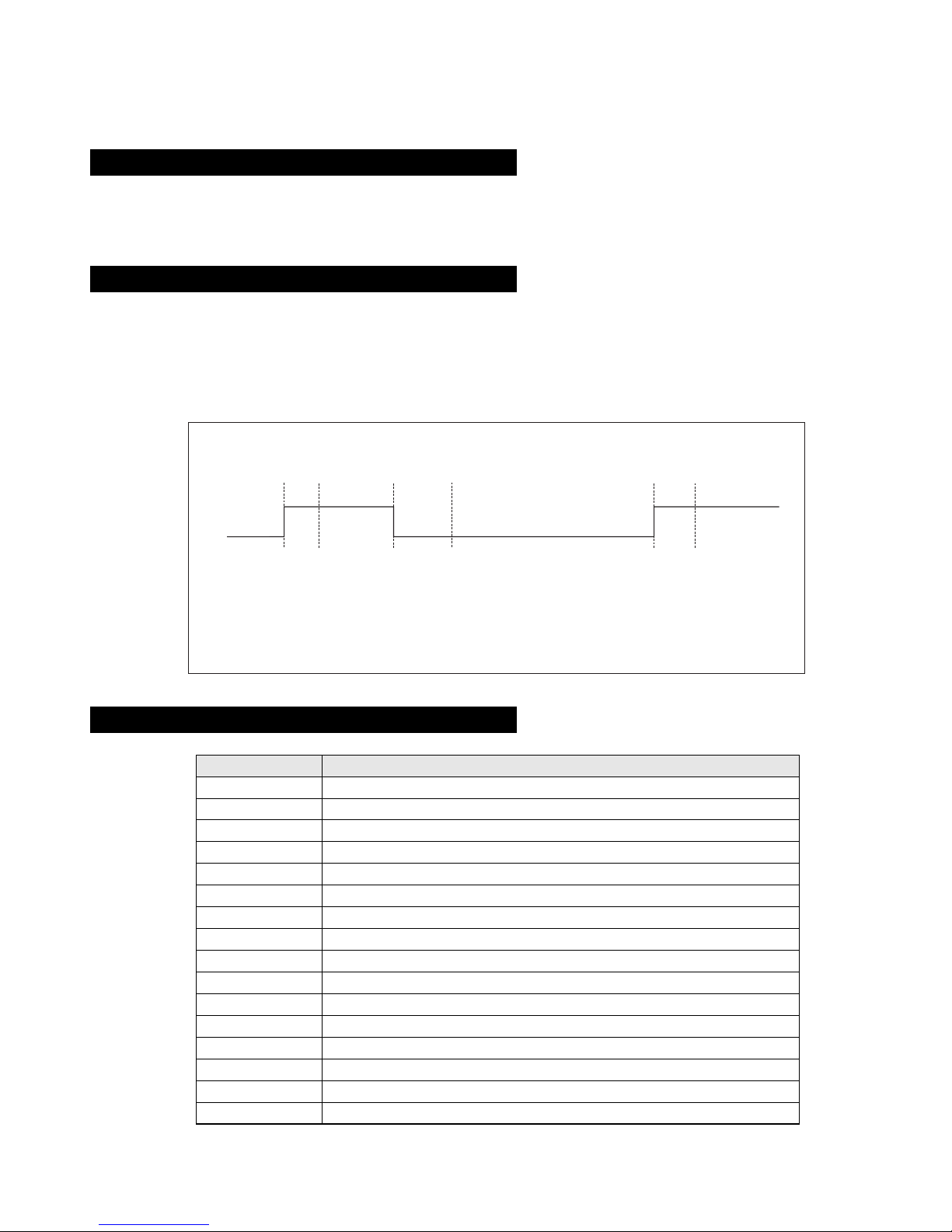
AKB Error (Error 5):
Startup Diagnostic Errors (Errors 6-18, 27, 29-32):
10090807050 60403020100
Time / seconds
IKR
Return
A
BCD EF
A. IKR Return first goes high after 12 seconds.
B. Micro begins checking IKR Return status 20 seconds after power on.
C. Micro detects IKR return = 0.
D. Micro detects that IKR has been 0 for 10 seconds; NVM counter is incremented and the LED
starts flashing (flashes 5 times, off for 2 seconds, flashes 5 times, etc.
E. Micro detects that IKR=1; LED continues to flash.
F. Micro detects that IKR has been high for 10 seconds; LED stops flashing.
NVM Error Description
6 SCL pin low
7 SDA pin low
8 Both SCL and the SDA pins are low
9 No acknowledge from the jungle (CXA2076)
10 No acknowledge from the video switch (CXA2040)
11 No acknowledge from the tuner
12 No acknowledge from the MSP
13 No acknowledge from the NVM
14 No acknowledge from the CXA2089 video switch (DS20 & DX20)
16 No acknowledge from the CXA1875 video Port Expander (DS20 & DX20)
18 No acknowledge from the Dynamic Convergence (CXA8070)
27 M3L_TXD pin low after Compact Text RAM test.
29 M3L_TXD pin low
30 M3L_RXD pin low
31 M3LEN pin low
32 Compact Text RAM test fail
Once every main loop (approximately 200ms OSD mode, 50ms text or menu mode), the micro checks the protection pin (pin 66). If the protection
pin is high 6 successive times, a protection error is diagnosed. The protection pin is not checked during the first 3 - 4 seconds after AC on.
If this error is diagnosed, the respective NVM register will be updated and the set goes straight into diagnostic standby with 2 flashes - no reset is
attempted.
Once every main loop the micro checks the AKB stability by reading the IKR return from the Jungle IC. IKR=1 means that the AKB is stable,
IKR=0 means that the AKB is unstable. If the AKB status is unstable for 10 seconds, an AKB error is diagnosed. AKB stability is not checked
during the first 20 seconds after AC switch on.
If this error is diagnosed, the respective NVM register will be updated and the response LED will flash 5 times continually, but the set will not go
into standby mode. If the AKB status becomes stable, and remains stable for 10 seconds, the LED will stop flashing.
If any of these errors are detected, the respective NVM register will be incremented. The software will then carry on with the power up sequence.
8
General IIC Device Run-time Errors (Errors 19-23):
Compact Text Run-time Errors (Errors 26, 28, 33 & 34):
MSP and DSP Run-time Errors (Errors 24 & 25):
If any of these errors are detected, the respective NVM register will be incremented and the software will carry on.
NVM Error Description
19 No acknowledge from Jungle when attempting to initialise.
20 No acknowledge from Jungle when attempting to read registers.
21 AV Switch cannot complete reset during initialisation.
22 No acknowledge from AV Switch when attempting to read registers.
23 No acknowledge from NVM when attempting to read or write.
In the case of these errors, the ‘device reset’ pin will be held low for 60ms, causing a hardware reset of Compact Text. Following this reset, a
longer timeout will be allowed for the M3L bus to reco ver. If the error still e xists, the NVM register will be incremented and the software will carry
on.
NVM Error Description
26 M3L_TXD pin low when checking register 81 (implies that no communication was
possible).
28 M3L_TXD pin low when attempting to initialise (implies that no communication was
possible).
33 Compact Text RAM test failed during initialisation of devices.
In the case, the ‘device reset’ pin will be held low for 60ms, causing a hardware reset of Compact Text. Compact T ext will then be re-initialised and
the NVM counter updated. This is the same as for errors 26, 28 and 33 except that the M3L bus timeout is not changed.
NVM Error Description
34 Register 81 check fail, but M3L_TXD pin high (implies that Compact Text has either
reset or become corrupted).
For both these errors, the software will refresh the MSP and DSP registers. If the errors still exist, the NVM counter will be incremented, and the
software will carry on.
NVM Error Description
24 Error 24 can be caused by any of the following :
- After MSP initialisation, Scart Prescale Register check fail (implies that the MSP
has either reset or become corrupted).
- MSP fails to acknowledge reset instruction.
- Scart Prescale Register check fail (implies that the MSP has either reset or
become corrupted).
25 - DSP test byte corrupted (implies that the MSP has either reset or become
corrupted).

9
Error Display Mode
Error Display Mode is entered by the following sequence of commands :
Standby -> Information -> Digit 5 -> Volume Down -> TV
This mode will display a special menu, which will list all possible errors and the number of occurrances of each error (0 - 255, as stored in the
NVM). There will also be a display of the current error (00 if no error). This display mode will appear as follows :
ERROR DISPLAY MODE
Current Error Code = 00
Error Code Occurrences Error Code Occurrences
2 2 19 0
3 -- 20 0
4 -- 21 0
5 0 22 0
6 0 23 0
7 0 24 0
8 0 25 4
9 0 26 5
10 0 27 89
11 0 28 3
12 0 29 0
13 0 30 0
14 0 31 0
15 3 32 0
16 0 33 3
17 0 34 38
18 6
Whilst in this mode, the number of occurences of each error can be reset to 0 by following sequence of Sircs commands: Digit 8 -> Digit 0.
‘TT08’ will also reset this NVM data.
This mode can only be exited by switching off the TV.
The Current Error Code can also be read by using a TV Error Reader (IIC slave address 42H). This de vice simply recei ves 1 data b yte, which is the
error number in binary coded decimal form.
10
8
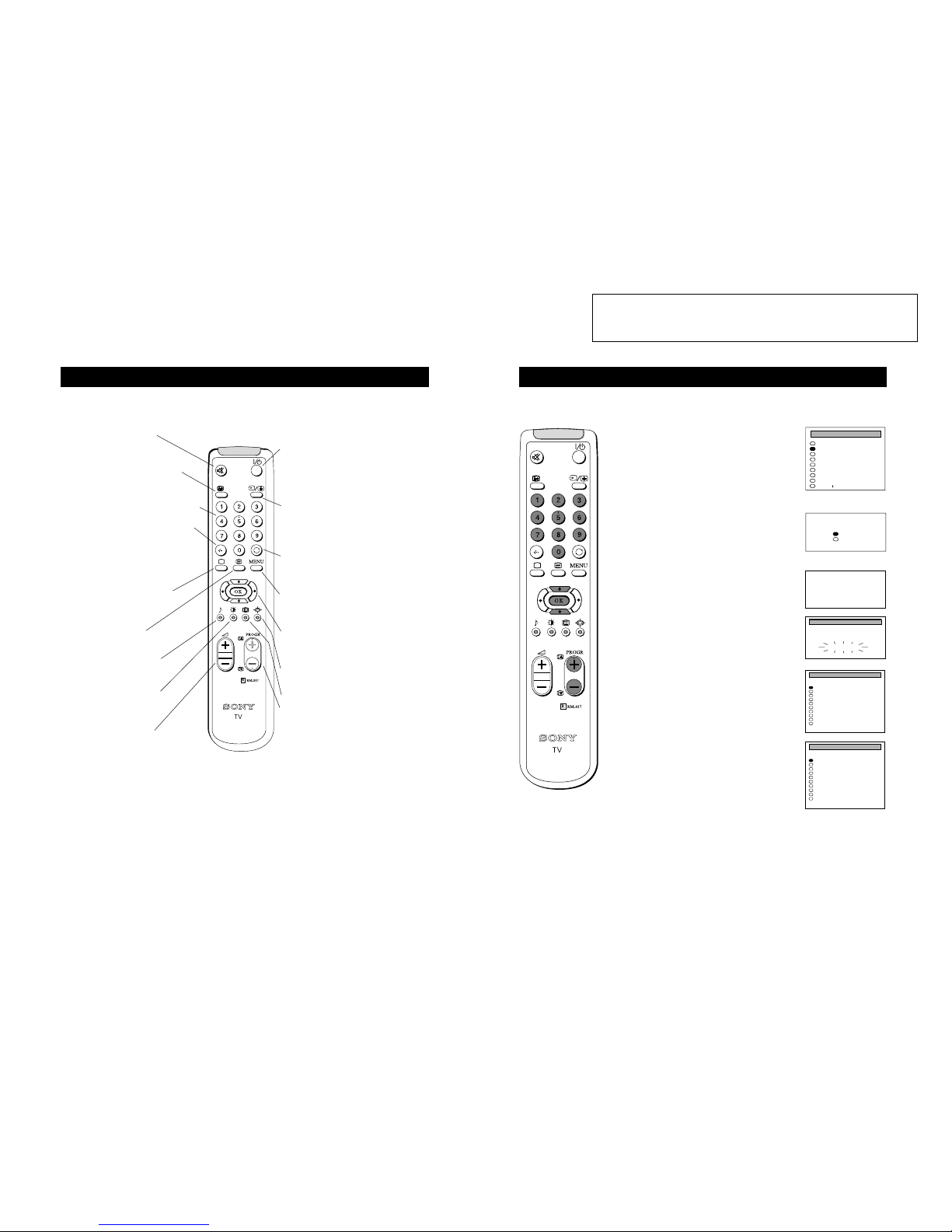
Overview
Overview of the remote control buttons
To mute sound
Press to mute TV sound. Press
again to restore the sound.
To display sound menu
Press to change the sound settings.
Press again to remove the display.
To adjust TV volume
Press to adjust the volume of the TV.
To temporarily switch off TV
Press to temporarily switch off TV. Press again
to switch on TV from standby mode.
To save energy we recommend switching off
completely when TV is not in use.
NOTE: After 15 -30 minutes without a TV
signal and without any button being pressed, the
TV switches automatically into standby mode.
To reveal on screen information
Press to reveal all on-screen indications.
Press again to cancel.
To select channels
Press to select channels.
To change screen format
Press to change the size of the screen.
To display picture menu
Press to change the picture settings.
Press again to remove the display.
To select teletext
Press to switch on Teletext.
To return to TV mode
Press to return to the normal operation
from teletext mode or standby mode.
To select menu items
Use the OK button and arrow keys to
select the options available in the menu
system of this TV.
To select input signal or freeze teletext
Press to select inputs from the TV sockets (see
Using Optional Equipment section). In teletext
mode, press to freeze the displayed page. Press
once again to cancel.
To display the menu
Press if you wish to use the TV menu
system. Press again to remove the menu
from the TV screen.
To select channels
Press the numbered buttons to select channels.
For double digit programme numbers, e.g.23,
press -/-- first, then the buttons 2 and 3.
If you enter an incorrect first digit, this should
be corrected by entering another digit (0 - 9)
and then selecting -/-- button again to enter the
programme number of your choice.
This button has no function
To return to previous channel
Press to return to the previous channel
you were watching. Note: This can be
done only after watching the present
channel for 5 seconds
6
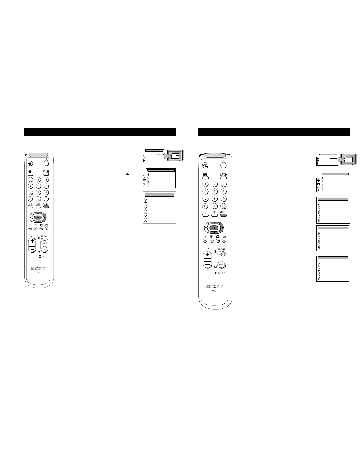
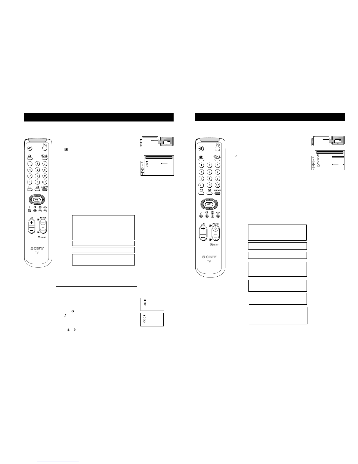
6. Automatically tuning the TV
1 When switching on the TV for the first time, the
‘LANGUAGE’ menu appears automatically on the TV
screen enabling you to select in which language you
wish to read the TV menu screens. Press the UP and
DOWN arrow keys on the remote control to select your
language then press the OK button to confirm your
selection.
2 The ‘AUTO TUNE’ menu appears on the TV screen in
your selected language. Press the UP and DOWN arrow
keys to select ‘YES’ then press the OK button to
confirm.
3 A new menu appears asking you to check that the
antenna is connected. Ensure that the antenna is
connected then press the OK button to confirm. The TV
now starts to automatically search and store all available
channels for you. Please be patient and do not press any
buttons.
4 When the TV has finished tuning in all available
channels, the ‘PROGRAMME SORTING’ menu appears
on the TV screen which enables you to change the
channel order on your TV. If you wish to change the
order of any of the TV channels, press the PROGR+/button on your remote control until the channel you wish
to rearrange appears on the screen. Press the UP or
DOWN arrow keys to select the new programme number
position for your selected channel. Press the OK button
to confirm. Repeat this procedure if you wish to change
the order of other channels on your TV.
5 Press the MENU button to remove the menu from the
TV screen.
6 Press the PROGR+/- or the numbered buttons on the
remote control to view the TV channels.
Quick Start Guide
When you first switch on the TV, the following sequence of menu screens appear on the TV enabling you to 1) choose a
language for the TV menu screens, 2) add channels to the TV, 3) arrange the channels.
6
B/G
SYSPROG
C26
CHAN
- - - - -
LABEL
AUTO PROGRAMME
AUTO PROGRAMME
Please confirm that
antenna is connected
Confirm: OK
English
Deutsch
Français
Italiano
Nederlands
PolskiÈ
Česky
Magyar
Eλλnν kά
LANGUAGE
Yes
No
Do you want to start
automatic tuning?
Confirm: OK
0
1
2
3
4
5
6
7
8
9
B/G
B/G
B/G
B/G
B/G
B/G
B/G
B/G
B/G
B/G
SYS
PROG
C28
C29
C35
C38
C40
C42
C55
C56
C57
C58
CHAN
BBC-W
VHS-2
CNN- -
- - - - MV-CH
VHS-1
- - - - 8MM
- - - - -
- - - - -
LABEL
PROGRAMME SORTING
Select: OK Exit: MENU
0
1
2
3
4
5
6
7
8
9
B/G
B/G
B/G
B/G
B/G
B/G
B/G
B/G
B/G
B/G
SYS
PROG
C28
C29
C35
C38
C40
C42
C55
C56
C57
C58
CHAN
BBC-W
VHS-2
CNN- -
- - - - MV-CH
VHS-1
- - - - 8MM
- - - - -
- - - - -
LABEL
PROGRAMME SORTING
Select Position: 4$ Confirm: OK
SECTION1GENERAL
Theoperatinginstructionsmentionedherearepartialabstracts
fromtheOperatingManual.ThepagenumbersoftheOperating
InstructionManualremainasinthemanual.
11
9
Choosing a language for the TV menu screens
1 Press the MENU button on the remote control to display
the menu on the TV screen.
2 Press the UP or DOWN arrow keys to select the
symbol on the menu screen then press the RIGHT arrow
key to enter the ‘PRESET’ menu
3 Press the UP or DOWN arrow keys to select ‘Language’
on the menu screen then press the RIGHT arrow key to
enter the ‘LANGUAGE’ menu.
4 Press the UP or DOWN arrow keys to select your chosen
language.
5 Press the OK button to confirm your selection.
6 Press the MENU button to remove the display from the
TV screen.
Additional TV Features
The TV consists of a menu system which can appear on screen in a variety of languages. Use the following feature to select
the language that best suits you.
English
Deutsch
Français
Italiano
Nederlands
PolskiÈ
Česky
Magyar
Eλλnν kά
LANGUAGE
PICTURE CONTROL
Contrast
Reset
FormatFormat
Picture Mode
Personal
. . . . . . . . .
Wide
PICTURE CONTROL
Contrast
Reset
FormatFormat
Picture Mode
Personal
. . . . . . . . .
Wide
Auto Programme
Manual Programme
Further Programme Preset
AV Label Preset
Programme Sorting
Parental Lock
Language
Picture Rotation
0
PRESET
11
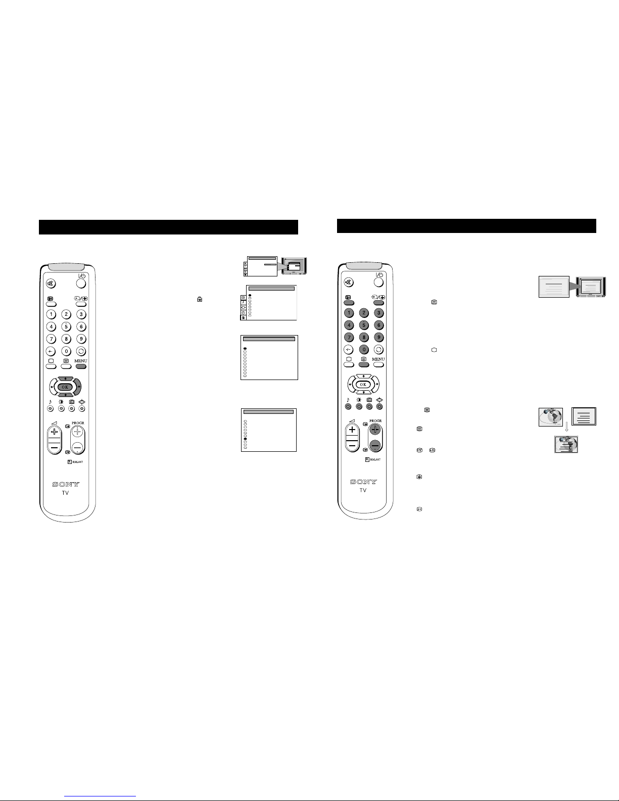
Re-arranging the TV channels
Additional TV Features
After automatically tuning the TV, you can use this feature to change the channel order. You may wish for example to
exchange the channel on programme number 8 with the channel on programme number 4.
1 Press the MENU button on the remote control to display
the menu on the TV screen.
2 Press the DOWN arrow key on the remote control to
select the symbol on the menu screen then press the
RIGHT arrow key to enter the ‘PRESET’ menu.
3 Press the DOWN arrow key to select ‘Programme
Sorting’ then press the RIGHT arrow key to enter the
‘PROGRAMME SORTING’ menu.
4 Press the UP or DOWN arrow keys to select the
programme position of the channel you want to move
(e.g. PROG 8) then press the OK button to confirm.
5 Press the UP or DOWN arrow keys to select the new
programme position for your selected channel (e.g.
PROG 4) then press the OK button to confirm. The two
selected channels now exchange position.
6 Repeat steps 4 and 5 if you wish to sort other channels.
7 Press the MENU button to remove the menu from the
TV screen.
PICTURE CONTROL
Contrast
Reset
FormatFormat
Picture Mode
Personal
. . . . . . . . .
Wide
PICTURE CONTROL
Contrast
Reset
FormatFormat
Picture Mode
Personal
. . . . . . . . .
Wide
Auto Programme
Manual Programme
Further Programme Preset
AV Label Preset
Programme Sorting
Parental Lock
Language
Picture Rotation
0
PRESET
0
1
2
3
4
5
6
7
8
9
BG
BG
BG
BG
BG
BG
BG
BG
BG
BG
SYS
PROG
C28
C29
C35
C38
C40
C42
C55
C56
C57
C58
CHAN
BBC-W
VHS-2
CNN- -
- - - - MV-CH
VHS-1
- - - - 8MM
- - - - -
- - - - -
LABEL
PROGRAMME SORTING
0
1
2
3
4
5
6
7
8
9
BG
BG
BG
BG
BG
BG
BG
BG
BG
BG
SYS
PROG
C28
C29
C35
C38
C40
C42
C55
C56
C57
C58
CHAN
BBC-W
VHS-2
CNN- -
- - - - MV-CH
VHS-1
- - - - 8MM
- - - - -
- - - - -
LABEL
PROGRAMME SORTING
0
1
2
3
4
5
6
7
8
9
BG
BG
BG
BG
BG
BG
BG
BG
BG
BG
SYS
PROG
C28
C29
C35
C38
C40
C42
C55
C56
C57
C58
CHAN
BBC-W
VHS-2
CNN- -
- - - - MV-CH
VHS-1
- - - - 8MM
- - - - -
- - - - -
LABEL
PROGRAMME SORTING
12
12
Adjusting the picture
Additional TV Features
Although the picture is adjusted at the factory, you can modify it to suit your own taste.
1 Press the MENU button on the remote control to display the
menu on the TV screen.
2 Press the UP or DOWN arrow key on the remote control to select
the symbol on the menu screen then press the RIGHT arrow
key to enter the ‘PICTURE CONTROL’ menu.
3 Press the UP or DOWN arrow keys to select the item on the
screen you wish to adjust then press the RIGHT arrow key to
confirm. For a description of the menu items and their effects,
see the table underneath.
4 If you selected ‘Picture Mode’ or ‘Format’ in step 3, press the UP
or DOWN arrow keys to select the item on the screen you wish
to adjust then press the RIGHT arrow key to confirm.
5 Press the RIGHT or LEFT arrow keys to adjust your selected
item.
6 As soon as you have adjusted the item, press the OK button to
store the new setting.
7 If you selected ‘Picture Mode’ or ‘Format’ in step 3, press the
LEFT arrow key to return to the ‘PICTURE CONTROL’ menu.
8 Repeat steps 3-7 to adjust the other items.
9 Press the MENU button to remove the menu from the TV screen.
Picture Mode Picture Mode B Personal (for individual settings)
Movie (for films)
b Live (for live broadcasts)
Brightness* B Darker b Brighter
Colour* B Less b More
Sharpness* B Softer b Sharper
Hue** B Greenish b Reddish
Contrast B Less b More
Reset Resets picture to factory preset levels
Format Format (refer to page 14 for details)
Scroll
Auto 16:9 B Off bOn
* Only if you select ‘Personal’ in ‘Picture Mode’.
**Available for NTSC colour system only.
Changing picture and sound modes quickly
You can quickly change the Picture Mode or the Equalizer Mode
without entering the ‘PICTURE CONTROL’ or the ‘SOUND
CONTROL’ menu screens.
1 Press the symbol on the remote control for picture modes or
the symbol for equalizer modes.
2 Press the UP or DOWN arrow keys to select the desired mode.
3 Press or again to remove the display from the TV screen.
PICTURE CONTROL
Contrast
Reset
FormatFormat
Picture Mode
Personal
. . . . . . . . .
Wide
PICTURE CONTROL
Contrast
Reset
FormatFormat
Picture Mode
Personal
. . . . . . . . .
Wide
PICTURE CONTROL
Contrast
Reset
FormatFormat
Picture Mode
Personal
. . . . . . . . .
Wide
Personal
Movie
Live
Personal
Rock
Jazz
Pop
13
Additional TV Features
Adjusting the sound
1 Press the MENU button on the remote control to display the
menu on the TV screen.
2 Press the DOWN arrow key on the remote control to select the
symbol on the menu screen then press the RIGHT arrow key
to enter the ‘SOUND CONTROL’ menu.
3 Press the UP or DOWN arrow keys to select the item on the
screen you wish to adjust then press the RIGHT arrow key to
confirm. For a description of the menu items and their effects,
see the table underneath.
4 If you selected ‘Sound Mode’ in step 3, press the UP or
DOWN arrow keys to select the item on the screen you wish to
adjust then press the RIGHT arrow key to confirm.
5 Press the RIGHT or LEFT arrow keys to adjust your selected
item.
6 As soon as you have adjusted the item, press the OK button to
store the new setting.
7 If you selected ‘Sound Mode’ in step 3, press the LEFT arrow
key to return to the ‘SOUND CONTROL’ menu.
8 Repeat steps 3-7 to adjust the other items.
9 Press the MENU button to remove the menu from the TV
screen.
Sound Mode B Personal
Jazz
Rock
b Pop
Balance Less BbMore
Reset Resets picture to factory preset levels
Spatial B On: volume level of the channels will
stay the same
b Off: volume level changes according
to the broadcast signal
Dual Sound StereoBbMono (for a stereo broadcast)
A for channel 1BbB for channel 2 (for a
bilingual broadcast)
Volume Offset B The channel volume level can be b
adjusted over a range of -12 to +12
Headphones
2 Volume Less BbMore
2 Dual Sound StereoBbMono (for a stereo broadcast)
A for channel 1BbB for channel 2
(for a bilingual broadcast)
Although the sound is adjusted at the factory, you can modify it to suit your own taste.
SOUND CONTROL
Balance
Reset
Spatial
Dual Sound
Volume Offset
Volume
Dual Sound
Sound Mode
Personal
. . . . . . . . .
Off
Mono
0
Mono
. . . . . . . . .
PICTURE CONTROL
Contrast
Reset
FormatFormat
Picture Mode
Personal
. . . . . . . . .
Wide
PICTURE CONTROL
Contrast
Reset
FormatFormat
Picture Mode
Personal
. . . . . . . . .
Wide
13
15
Manually fine tuning the TV picture
If the picture is distorted, you can manually fine-tune the TV to obtain a better picture reception.
1 Press the MENU button on the remote control to display
the menu on the TV screen.
2 Press the DOWN arrow key to select the symbol on
the menu screen then press the RIGHT arrow key to
enter the ‘PRESET’ menu.
3 Press the DOWN arrow key to select ‘Further
Programme Preset' then press the RIGHT arrow key to
enter the ‘FURTHER PROGRAMME PRESET’ menu.
4 Press the UP or DOWN arrow keys to select the
programme number you want to manually fine-tune.
5 Press the RIGHT arrow key repeatedly until the AFT
column is highlighted.
6 Press the UP or DOWN arrow keys to fine tune the
channel frequency over a range of -15 to +15.
7 Press the OK button to confirm.
8 Repeat steps 4 to 7 to fine-tune other channels.
9 Press the MENU button to remove the menu from the
TV screen.
PICTURE CONTROL
Contrast
Reset
FormatFormat
Picture Mode
Personal
. . . . . . . . .
Wide
PICTURE CONTROL
Contrast
Reset
FormatFormat
Picture Mode
Personal
. . . . . . . . .
Wide
Auto Programme
Manual Programme
Further Programme Preset
AV Label Preset
Programme Sorting
Parental Lock
Language
Picture Rotation
0
PRESET
0
1
2
3
4
5
6
7
8
9
PROG
Off
Off
AV1
Off
AV2
Off
Off
Off
Off
Off
DECODER
On
On
On
On
On
On
On
On
On
On
AFT
FURTHER PROGRAMME PRESET
0
1
2
3
4
5
6
7
8
9
PROG
Off
Off
AV1
Off
AV2
Off
Off
Off
Off
Off
DECODER
On
On
On
On
On
On
10
On
On
On
AFT
FURTHER PROGRAMME PRESET
Additional TV Features
22
Teletext
Teletext
Switching Teletext on and off
1 When viewing channels, press a number button on the
remote control to select the channel which carries the
teletext service you wish to receive.
2 Press the button on the remote control to switch on
teletext.
3 Input three digits for the page number using the
numbered buttons on the control. If you make a mistake,
type in any three digits then re-enter the correct page
number.
4 Press the button to switch off teletext.
NOTE: Teletext errors may occur if the broadcasting signals
are weak.
Using Other Teletext Functions
To superimpose teletext on to the TV
Press the button on the remote control once in teletext
mode or twice in TV mode to superimpose teletext on to the
TV screen.
Press button once more to cancel.
To Move to Next or Preceding Page
Press or
on the control to select the previous or next
page.
To Freeze a Teletext Page
Press on the control to freeze the page. Press again to
cancel the freeze.
Revealing concealed information (eg: answers
to a quiz).
Press to reveal information. Press again to conceal the
information.
Using Fastext
(only available if the TV station broadcasts Fastext signals)
When the colour coded menu appears at the bottom of a
page, press the colour button (green, red, yellow or blue) on
the control to access the corresponding page.
Index
TELETEXTTELETEXT
Programme
News
Sport
Weather
25
153
101
98
Index
TELETEXTTELETEXT
Programme
News
Sport
Weather
25
153
101
98
Index
TELETEXTTELETEXT
Programme
News
Sport
Weather
25
153
101
98
Index
TELETEXT
TELETEXT
Programme
News
Sport
Weather
25
153
101
98
Teletext is an information service transmitted by most TV stations.
14
26
Additional Information
Specifications
TV system
B/G/H
Colour system
PAL, SECAM
NTSC 3.58, 4.43 (only Video In)
Channel coverage
See ‘Receivable Channels’ table on next page
Picture tube
KV-28FX20D:
FD Trinitron WIDE
Approx. 71 cm (28 inches) (Approx. 66 cm picture measured diagonally),
102° deflection
KV-32FX20D:
FD Trinitron WIDE
Approx. 82 cm (32 inches) (Approx. 76 cm picture measured diagonally),
102° deflection
Rear Terminals
1
21-pin Euro connector (CENELEC standard) including audio/video
input, RGB input
2
/
s
2
21-pin Euro connector (CENELEC standard) including audio/video
input, S-video input, Monitor audio/video output
Audio outputs - phono jacks
Front Terminals
3
video input - phono jack
3
audio inputs - phono jacks
s
2
S video input - 4 pin DIN
Headphones jack - minijack stereo
Sound output:
Left, Right 2x20W (music power)
Subwoofer 20W (music power)
Power consumption
KV-28FX20D: 123 W
KV-32FX20D: 120 W
Dimensions (wxhxd)
KV-28FX20D: Approx. 761 x 496 x 525 mm
KV-32FX20D: Approx. 874 x 563 x 571 mm
Weight
KV-28FX20D: Approx. 44.0 kg
KV-32FX20D: Approx. 62.0 kg
Accessories supplied
RM-887 Remote Control (1)
IEC designated size AA battery (2)
Other features
TELETEXT
Design and specifications are subject to change without notice.
28
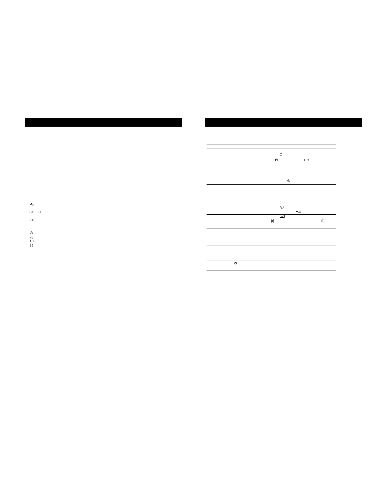
Troubleshooting
Additional Information
Problem Solution
No picture (screen is dark), • Plug the TV in.
no sound • Press the button on the front of TV.
• If the indicator is on press /button or a
programme number button on the remote control.
• Check the aerial connection.
• Check that the selected video source is on.
• Turn the TV off for 3 or 4 seconds and then turn it on
again using the button on the front of the TV.
Poor or no picture (screen is dark), • Using the MENU system, select the Picture
but good sound. Control and Picture Mode displays. Adjust the
contrast, brightness, and colour levels.
• From the Picture Control display select RESET to
return to factory settings.
Poor picture quality when watching • Press the button repeatedly on the remote control
a RGB video source. until the RGB symbol is displayed on the screen.
Good picture, no sound • Press the +/– button on the remote control.
• If is displayed on the screen, press the button
on the remote control.
No colour on colour programmes • Using the MENU system, select the Picture Mode
display. Adjust the the colour level setting.
• From the Picture Control display select RESET to
return to factory settings.
Distorted picture when changing • Turn off any equipment connected to the 21 pin
programmes or selecting teletext Euro connectors on the rear of the TV.
Remote control does not function • Replace the batteries.
The standby indicator on the TV • Contact your nearest Sony service centre.
flashes
• If you continue to have these problems, have your TV serviced by qualified personnel.
• NEVER open the casing yourself.
Here are some simple solutions to problems which may affect the picture and sound.
15
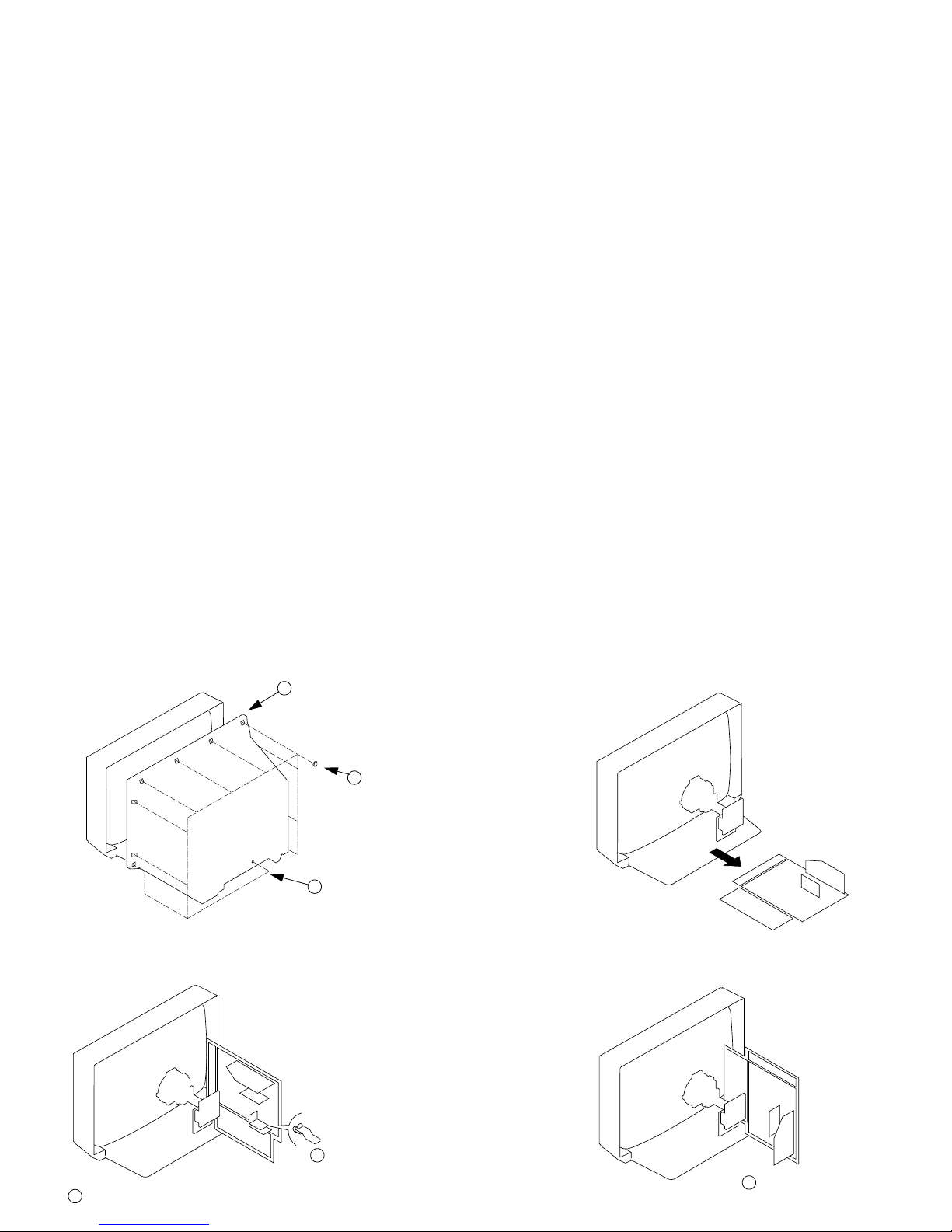
SECTION 2
DISASSEMBLY
3 Rear Cover
1 1 Screw (BTVP 4x16)
2-1. REAR COVER REMOVAL
2-2. CHASSIS ASSY REMOVAL
2-3-2. SERVICE POSITION (2) 2-3-1. SERVICE POSITION (1)
2 8 Screws
(BTVTP 4x16)
1 Snap off from main bracket
2 Insert into heatsink
1 Clip bracket into Beznet
16
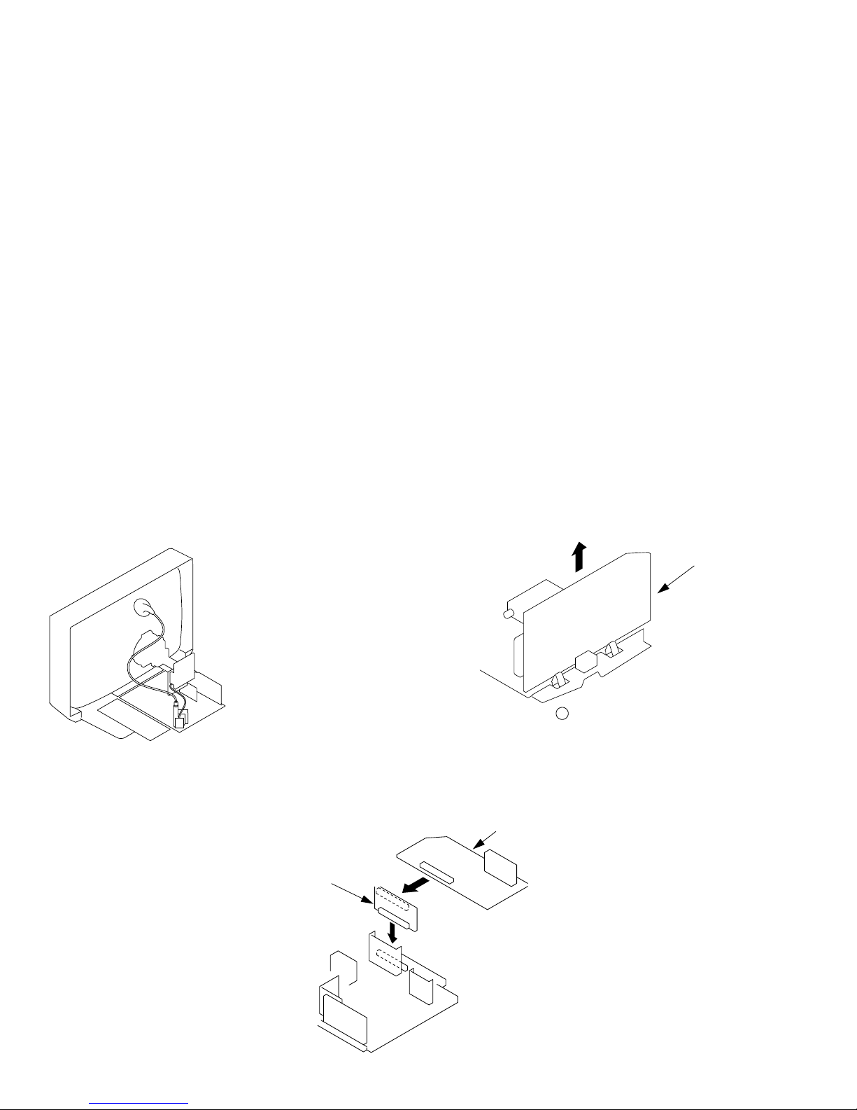
2-4. WIRE DRESSING
2-5. A BOARD REMOVAL
2-6. A EXTENSION BOARD
1 Remove CN301 before removing A board
A Board
A board
BE-3E Extension Board
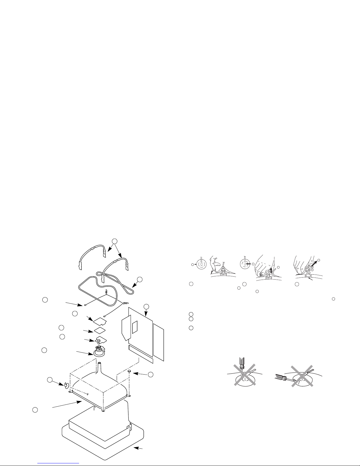
17
5 Neck assy
Cushion
8 Degaussing coils
9 Spring Extension
2 Chassis assy
10 Four PT screws
11 Picture tube
2-7. PICTURE TUBE REMOVAL
Anode button
a
* REMOVING PROCEDURES.
Turn up one side of the rubber cap in
the direction indicated by the arrow a
1
2 Using a thumb pull up the rubber cap
firmly in the direction indicated by the
arrow b
3 When one side of the rubber cap is
separated from the anode button, the
anode-cap can be removed by turning
up the rubber cap and pulling it up in
the direction of the arrow c
b
b
c
Note : Short circuit the anode of the picture tube and the anode cap to the metal chassis, CRT
shield or carbon paint on the CRT, after removing the anode.
• REMOVAL OF ANODE-CAP
• HOW TO HANDLE THE ANODE-CAP
1 To prevent damaging the surface of the anode-cap do not use sharp materials.
2 Do not apply too great a pressure on the rubber, as this may cause damage to the
anode connector.
3 A metal fitting called a shatter hook terminal is fitted inside the rubber cap.
Do not turn the rubber foot over excessively this may cause damage if the shatter
hook sticks out.
3 C board
Anode cap
1
7 DGC holders
6 Deflection yoke
4 VM Board

18
Fig 2
NUMERICAL MARKINGS
ATTENTIONATTENTION
THIS PLATE MUST BE REMOVED
(TURN 180' NOT FLIP OVER)
AFTER CUTTING AWAY
FOR SAFETY REASONS
THIS PLATE MUST BE REMOVED
AFTER CUTTING AWAY FOR THE SAFETY REASON.
22
2
2
1
1
44
3
4
4
REFITTING REFITTING
ATTENTIONATTENTION
THIS PLATE MUST BE REMOVED
(TURN 180' NOT FLIP OVER)
AFTER CUTTING AWAY
FOR SAFETY REASONS
22
2
2
1
1
Cut points
Fig 1
MAIN BRACKET
INSERT FROM
THE BOTTOM
SIDE
FIG 3
Fig 4
REMOVAL AND REPLACEMENT OF THE MAIN-BRACKET
BOTTOM PLATES.
(1) REMOVING THE PLATES
In the event of servicing being required to the solder side of the D Board printed
wiring board, the bottom plates fitted to the main chassis bracket require to be
removed.
This is performed by cutting the gates with a sharp wire cutter at the locations
indicated by arrows.
Note :There are 4 plates fitted to the main bracket and secured by 6 gates.
Only remove the necessary plate to gain access to the printed wiring board.
(2) REFITTING THE PLATES
Because the plates differ in size it is important that the correct plates are refitted in
their original location.
The plates are identified by numerical markings on their top side e.g. 1,2
1. Identify the plate by locating its marking.
2. Rotate the plate through 180’ (do not flip over).
3. Locate the corresponding numerical markings indicated on the main
chassis. See Fig 2.
4. Refit the plate as indicated in Fig 3 with the markings located next to each
other.
£
For safety reasons, on no account should the plates be
removed and not refitted after servicing.
In the event of the plates requiring to be removed
at a later stage, this can be achieved by inserting a
screwdriver in the snap-recess indicated as in Fig 4
and lifting out.

SECTION 3
SET-UP ADJUSTMENTS
• When complete readjustment is necessary or a new
picture tube is installed, carry out the following
adjustments.
• Unless there are specific instructions to the contrary,
carry out these adjustments with the rated power supply.
• Unless there are specific instructions to the contrary, set the
controls and switches to the following settings:
Contrast ............... normal
Brightness ............... normal
3-1.BEAM LANDING
Preparation:
1. In order to reduce the influence of geomagnetism on the set’s
picture tube, face it in an easterly or westerly direction.
2. Switch on the set’s power and degauss with the
degausser.
(1) Adjustment of Correction Magnet for Y-Splitting
Axis
1. Input a crosshatch signal from the pattern generator.
2. Set the Picture control to minimum and confirm that the
Brightness control is set to normal.
3. Position the neck assembly as indicated in Fig.3-2.
4. Move the deflection yoke as far forward as is possible.
5. Adjust the upper and lower pin symmetrically by opening or
closing the Y-splitting axis correction magnets located on the
neck assembly.
6. Return the deflection yoke to its original position.
Carry out the following adjustments in this order:
3-1. Beam Landing
3-2. Convergence
3-3. Focus
3-4. White balance
Note: Test equipment required
1. Color bar/pattern generator.
2. Degausser.
3. Digital multimeter.
4. Oscilloscope.
(2) Landing
Note :Before carrying out the following adjustments
adjust the magnets as indicated below [See Fig.3-3].
1. Input an all-white signal from the pattern generator.
Maximize the picture setting and adjust the Brightness
setting.
2. Rough-adjust the focus and horizontal convergence.
3. Loosen the deflection yoke screws and align the purity
adjustment knob to its central position. [See Fig.3-1].
4. Switch from the all-white pattern to an all-green pattern.
5. Move the deflection yoke backwards and adjust with the
purity magnet so that the green is at the centre and it aligns
symmetrically. [See Fig.3-4].
6. Move the deflection yoke forward and adjust so that the
entire screen becomes green.
7. Switch the raster signal to red, then to blue and verify the
landing condition.
8. When the position of the deflection yoke has been determined,
fasten the deflection yoke with the screw.
9. If the beam does not land correctly in all the corners of the
screen, use magnets to correct it. [See Fig.3-5].
Y-splitting axis correction magnet
Caution :
High voltages are present on the Deflection yoke terminals take care when handling the Deflection yoke whilst carrying
out adjustments.
19
Purity
Fig.3-1
Deflection yoke
Align the bottom edge
of the neck assy with
the G3 hole centre.
Fig.3-3
Align Pips
on each
magnet
Neck assy
Fig.3-2
 Loading...