

Sony Trinitron KV-29LS30E, Trinitron KV-29LS30K, Trinitron KV-29LS35B, Trinitron KV-29LS35E, Trinitron KV-29LS35K Service Manual
...
1
SERVICE MANUAL
FE-2
CHASSIS
MODEL
COMMANDER DEST CHASSIS NO.
KV-29LS30E
RM-887 ESP SCC-Q53F-A
KV-29LS30K
RM-887 OIRT SCC-Q51G-A
KV-29LS30U
RM-887 UK SCC-Q52F-A
MODEL
COMMANDER DEST CHASSIS NO.
RM-889
KV-29LS35B
RM-932 FR SCC-Q54F-G
KV-29LS35E
RM-932 ESP SCC-Q53G-A
KV-29LS35K
RM-932 OIRT SCC-Q51H-A
RM-887
RM-932
6
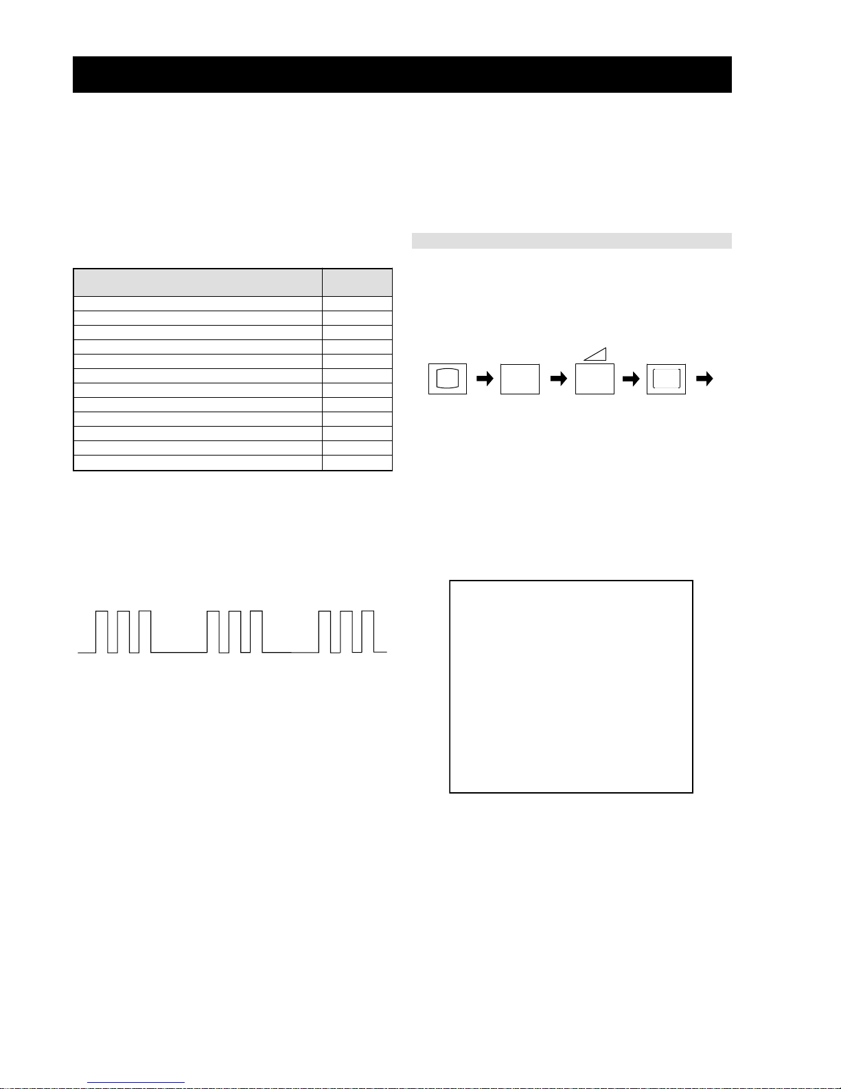
FE-2 SELF DIAGNOSTIC SOFTWARE
The identification of errors within the FE-2 chassis is triggered in one of two ways :- 1: Busy or 2: Device failure to respond to IIC. In the event
of one of these situations arising the software will first try to release the bus if busy (Failure to do so will report with a continuous flashing
LED) and then communicate with each device in turn to establish if a device is faulty . If a de vice is found to be faulty the relev ant device number
will be displayed through the LED (Series of flashes which must be counted) See table 1., non fatal errors are reported using this method.
Each time the software detects an error it is stored within the NVM. See Ta ble 2.
Flash Timing Example : e.g. err or number 3
StBy LED
ON ON ON
OFF
OFF
Table 1
How to enter into Table 2
1. Turn on the main power switch of the TV set and enter into
the
‘Stanby Mode’.
2. Press the following sequence of buttons on the Remote
Commander.
i+
5
-
(ON SCREEN (DIGIT 5) (VOLUME -) (TV)
DISPLAY)
3. The following table will be displayed indicating the error
count.
Table 2
Note: T o clear the error count data press ‘80’ on the Remote
commander.
UNEMRORRE
20E
30E
40E
50E
60E
70E
80E
90E
01E
11E
EMITGNIKROW
SRUOH
SETUNIM
PCO
A/NPVO
CNYSV
RKI
CII
MVN
ELGNUJ
RENUT
PDNUOS
V8
)552,0(
)552,0(
)552,0(
)552,0(
)552,0(
)552,0(
)552,0(
)552,0(
)552,0(
)552,0(
0
0
0
0
0
0
0
0
0
0
2
11
egasseMrorrE
DEL
edoC
rorreoN00
devreseR10
)noitcetorPtnerruCrevO(PCO20
desUtoN30
cnySlacitreVoN40
norewoptarorrERKI50
norewoptawolsenilatadro/dnakcolcsubCII60
norewoptaegdelwonkcasubCIIonMVN70
desUtoN80
norewoptaegdelwonkcaonrenuT90
rorrErossecorPdnuoS01
rorrestlov8rellortnocelgnuJ11
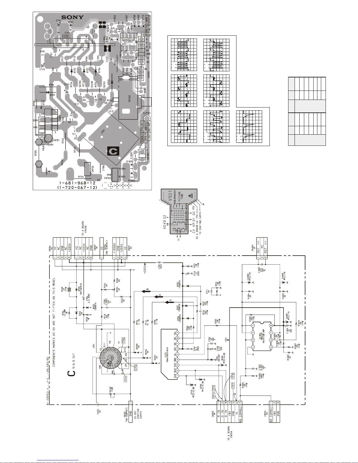
C [ R,G,B OUT ]
27 28
IC Volta ge Table
C board Waveforms
20us/div
1.88 Vp-p (H)
TP3
20us/div
1.88 Vp-p (H)
TP2
20us/div
74 Vp-p (H)
TP5
20us/div
74 Vp-p (H)
TP6
20us/div
1.76 Vp-p (H)
TP7
10us/div
1.77 Vp-p (H)
TP1
20us/div
TP4
74 Vp-p (H)
TP4
C Board W aveforms
oNfeR
oNniP )V(egatloV
oNfeR
oNniP
)
V(egatloV
1071CI
11.3
1081CI
13.1
21.223.1
30.334.1
55.551.4
713161.4
832170.7
96.42180.8
 Loading...