

Sony Trinitron KV-28DC20B Service Manual

SERVICE MANUAL
BE-3E
CHASSIS
MODEL
KV-28DC20B
COMMANDER DEST CHASSIS NO.
RM-931 FR SCC-Q23D-A
MODEL
COMMANDER DEST CHASSIS NO.
AB
CED
LUN MAR MER
JEU
VEN
DIM JOURNEE NUIT
SOIREE
PREFER -/--
SERV PERSO
PILOTE PROGR
MENU
TV
TV/SAT
SAM
SORTIE
PROGR
R
RM-931
1

TABLE OF CONTENTS
Section Title Page Section Title Page
Specifications .................... 3
Connectors .................... 4
Self Diagnostic Software .................... 5
1. GENERAL
Automatically Tuning the TV .................... 9
Adjusting the Picture & Sound .................... 10
Using the Further Programme
Preset Feature .................... 11
Manually Tuning the TV .................... 12
T eletext .................... 13
Specifications .................... 15
Troubleshooting .................... 15
2. DISASSEMBLY
2-1. Rear Cover Removal .................... 16
2-2. Chassis Assy Removal .................... 16
2-3-1. Service Position(1) .................... 16
2-3-2. Service Position(2) .................... 16
2-4. Wire Dressing .................... 17
2-5. A Board Removal .................... 17
2-6. A Extension Board .................... 17
2-7. Picture Tube Removal .................... 18
Removal and Replacement of
the Main-Bracket Bottom Plates.................... 19
3. SET-UP ADJUSTMENTS
3-1. Beam Landing .................... 20
3-2. Convergence .................... 21
3-3. Screen (G2) .................... 23
3-4. Focus .................... 23
3-5. White Balance .................... 23
5. DIAGRAMS
5-1. Block Diagram (1) .................... 29
Block Diagram (2) .................... 33
Block Diagram (3) .................... 37
Block Diagram (4) .................... 41
5-2. Circuit Board Location .................... 44
5-3. Schematic Diagrams and
Printed Wiring Boards .................... 44
* C Board .................... 45
* D Board .................... 49
* VM Board .................... 52
* H Board .................... 53
* D2 Board .................... 55
* J4 Board .................... 56
* N Board .................... 59
* J3 Board .................... 74
* J5 Board .................... 76
* D1 Board .................... 77
* A Board .................... 83
* A2 Board .................... 89
5-4. Semiconductors .................... 95
5-5. IC Blocks .................... 97
6. EXPLODED VIEWS
6-1. Chassis .................... 99
6-2. Picture Tube .................... 100
7. ELECTRICAL P ARTS LIST .................... 101
4. CIRCUIT ADJUSTMENTS
4-1. Electrical Adjustments .................... 24
4-2. ‘TT’ T est Mode .................... 27
4-3. ‘T’ T est Mode .................... 28
CAUTION
SHORT CIRCUIT THE ANODE OF THE PICTURE TUBE AND THE
ANODE CAP TO THE METAL CHASSIS, CRT SHIELD, OR THE
CARBON PAINTED ON THE CRT, AFTER REMOVAL OF THE
ANODE CAP.
WARNING !!
AN ISOLATION TRANSFORMER SHOULD BE USED DURING ANY
SERVICE WORK TO AVOID POSSIBLE SHOCK HAZARD DUE TO
LIVE CHASSIS, THE CHASSIS OF THIS RECEIVER IS DIRECTLY
CONNECTED TO THE POWER LINE.
SAFETY-RELATED COMPONENT WARNING !!
COMPONENTS IDENTIFIED BY SHADING AND MARKED
THE SCHEMATIC DIAGRAMS, EXPLODED VIEWS AND IN THE
PARTS LIST ARE CRITICAL FOR SAFE OPERATION. REPLACE
THESE COMPONENTS WITH SONY PARTS WHOSE PART
NUMBERS APPEAR AS SHOWN IN THIS MANUAL OR IN
SUPPLEMENTS PUBLISHED BY SONY.
£
ON
ATTENTION
APRES AVOIR DECONNECTE LE CAP DE’LANODE,
COURT-CIRCUITER L’ANODE DU TUBE CATHODIQUE ET CELUI
DE L’ANODE DU CAP AU CHASSIS METALLIQUE DE L’APPAREIL,
OU AU COUCHE DE CARBONE PEINTE SUR LE TUBE
CATHODIQUE OU AU BLINDAGE DU TUBE CATHODIQUE.
ATTENTION !!
AFIN D’EVITER TOUT RISQUE D’ELECTROCUTION PROVENANT
D’UN CHÁSSIS SOUS TENTION, UN TRANSFORMATEUR
D’ISOLEMENT DOIT ETRE UTILISÈ LORS DE TOUT DÈPANNAGE
LE CHÁSSIS DE CE RÈCEPTEUR EST DIRECTMENT RACCORDÈ
Á L’ALIMENTATION SECTEUR.
ATTENTION AUX COMPOSANTS RELATIFS Á
LES COMPOSANTS IDENTIFIÈS PAR UNE TRAME ET PAR UNE
MARQUE
EXPLOSÈES ET LES LISTES DE PIECES SONT D’UNE IMPOR-
TANCE CRITIQUE POUR LA SÈCURITÈ DU FONCTIONNEMENT,
NE LES REMPLACER QUE PAR DES COMPSANTS SONY DONT LE
NUMÈRO DE PIÈCE EST INDIQUÈ DANS LE PRÈSENT MANUEL
OU DANS DES SUPPLÈMENTS PUBLIÈS PAR SONY.
£
SUR LES SCHÈMAS DE PRINCIPE, LES VUES
LA SECURITÈ!!
2

LEDOMMETI metsySnoisiveleT metsySoeretS egarevoClennahC metsySroloC
RFI,L,K/D,H/G/BoeretSmaciN
ledoM B02CD82
noitpmusnoCrewoPW321
14S-1S:)1(VTELBAC
2H,1H,H-A:FHVAILATI
96B-12B:FHUI
96E-12E:FHU21E-2E:FHVH/G/B
01U-1U,01M-1M,50S-10S:)2(VTELBAC
50S-10S,96R-12R,21R-10R:KD
96F-12F:FHU,01F-2F:FHVL
44S-12S,Q-C,B:)1(VTELBAC
MACES,LAP
85.3CSTN,34.4CSTN
)NIOEDIV(
2GEPM
ediWnortinirTDF
)sehcni82(mc17xorppA
ebuTerutciP
derusaemerutcipmc66xorppA(
tuptuodnuoS
refoowbuS
)rewoPcisuM(W02x2
)rewoPcisuM(W02
)yllanogaid
noitcelfedeerged201
]RAER[slanimreTtuptuO/tupnI
stnemeriuqeRrewoPV042-022
.slangisoediVdnaoiduArofstupnI
rotcennocoruEnip-12
)dradnatsCELENEC(
.BGRrofstupnI
oiduAdnaoediVVTfostuptuO
snoisnemiDmm525x694x167xorppA
.slangis
.slangisoediVdnaoiduArofstupnI
2 rotcennocoruEnip-12:
.oediVSrofstupnI
.slangisoiduAdnaoediVVTfostuptuO
thgieWgk54xorppA
)tuorotinom(
.slangisoediVdnaoiduArofstupnI
3 rotcennocoruEnip-12:
.slangisoiduAdnaoediVVTfostuptuO
)elbatceles(
seirosseccAdeilppuS
medoM32V
)1(rednammoCetomeR139-MR
)2(yrettab6RdetangisedCEI
kcaJonohP
stuptuOoiduA
tuptuOoiduAlatigiDlacitpOenO
serutaeFrehtOtxeteleT
tekcoS
139-MR
]TNORF[slanimreTtuptuO/tupnI
metsyslortnocetomeRlortnocderarfnI
cdV3
kcajenohpdaeHkcajinimoerets stnemeriuqerrewoP
noitangisedCEIseirettab2
)AAezis(6R
tupni2oiduAskcajonohp snoisnemiD)d/h/w(mm32x902x44xorppA
tupni2oediVskcajonohp thgieW)yrettabgnidulcniton(g98xorppA
tupnioediVSNIDnip4
.ecitontuohtiwegnahcottcejbuserasnoitacificepsdnangiseD
metI B02CD82-VK metI B02CD82-VK
bmoClaP
PIP
ytiroirPBGR
xoBrefooW
1tracS
2tracS
)2(nitnorF
4tracS
rotcejorP
edom9:61niBKA
FFO
FFO
FFO
NO
NO
NO
NO
NO
FFO
NO
G/BmroN
ImroN
K/DmroN
SUAmroN
LmroN
TASmroN
MmroN
txeteleT
oeretSmaciN
teserPegaugnaL
NO
NO
NO
FFO
NO
NO
FFO
NO
NO
hcnerF
3
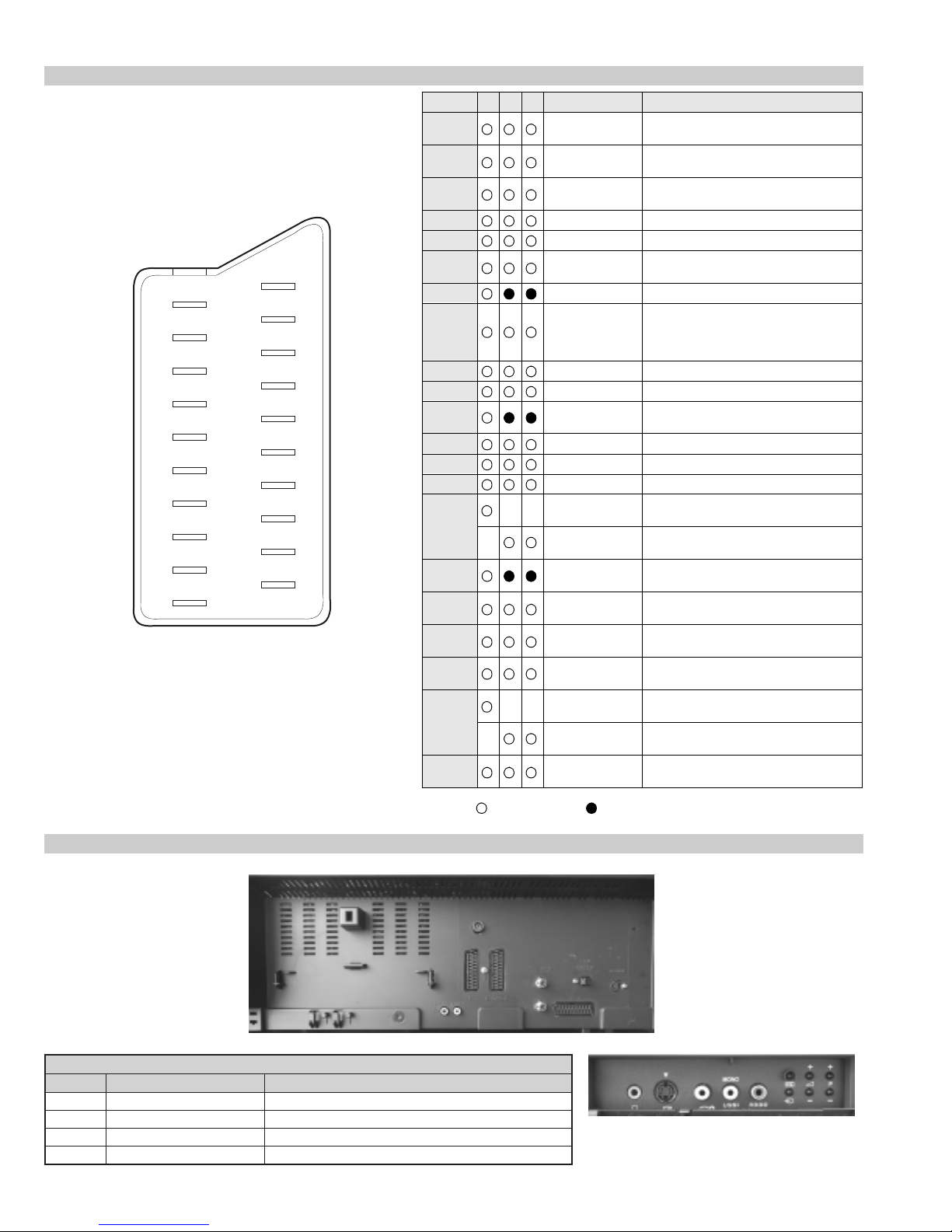
21 pin connector
21
19
17
15
13
11
9
7
5
3
1
20
18
16
14
12
10
8
6
4
2
Pin No 1 2 4 Signal Signal level
1 Audio output B
2
3
4 Ground (audio)
5 Ground (blue)
6 Audio input A
7 Blue input 0.7 +/- 3dB, 75 ohms positive
8 Function select
9 Ground (green)
10 Open
11 Green Green signal : 0.7 +/- 3dB, 75 ohms,
12 Open
13 Ground (red)
14 Ground (blanking)
15
_ (S signal Chroma
16 Blanking input
17 Ground (video
18 Ground (video
19 Video output 1V +/- 3dB, 75ohms, positive sync 0.3V
20
_ Video input
21 Common ground
(right)
Audio output B
(right)
Audio output A
(left)
(left)
(AV control)
_ _ Red input 0.7 +/- 3dB, 75 ohms, positive
input)
(Ys signal)
output)
input)
_ _ Video input 1V +/- 3dB, 75ohms, positive sync 0.3V
Y (S signal)
(plug, shield)
Standard level : 0.5V rms
Output impedence : Less than 1kohm*
Standard level : 0.5V rms
Output impedence : More than 10kohm*
Standard level : 0.5V rms
Output impedence : Less than 1kohm*
Standard level : 0.5V rms
Output impedence : More than 10kohm*
High state (9.5-12V) : Part mode
Low state (0-2V) : TV mode
Input impedence : More than 10K ohms
Input capacitance : Less than 2nF
positive
0.3 +/- 3dB, 75 ohms, positive
High state (1-3V) Low state (0-0.4V)
Input impedence : 75 ohms
(-3+10dB)
(-3+10dB)
1V +/- 3dB, 75ohms, positive sync 0.3V
(-3+10dB)
Rear Connection Panel
oNniP langiS leveLlangiS
1dnuorG2dnuorG3tupni)langisS(Y Bd01+3-V3.0.cnySevitisop,mho57Bd3-/+V1
4tupni)langisS(C.cnySevitisop,mho57Bd3-/+V3.0
Connected Not Connected (open) * at 20Hz - 20kHz
noitarugifnocniptekcosoediVS
S-Video
socket
4

BE-3E SELF DIAGNOSTIC SOFTWARE
The errors indicated below can be read using an Error Reader Display (Part Number S-188-900-10) connected to the service connector. Once an
error has been detected it will then be displayed on the two digit error reader. During the power up procedure and during normal run time, the micro’ s
self diagnostic procedures monitor for various errors. Errors displayed refer to the table indicated below.
rebmuNrorrE noitpircseDrorrE
00 )noitidnoclamronni00swohsredaeRrorrEVT(rorreoN
10 )DELnohsalfesnopserscriShtiwdesufnocebyam(dewollatoN
20)cnyS-VoN&PVO,PCO(pirttiucricnoitcetorP
30)E3-EBrof2rorrenidedulcnI(PVOrofdevreseR
40 )E3-EBrof2rorrenidedulcnI(cnyS-VoNrofdevreseR
50BKA
60>ylnopUrewoP<woLlcSCII
70>ylnopUrewoP<woLadSCII
80>ylnopUrewoP<woLlcS&adSCII
90>ylnopUrewoP<egdelwonkcaonrellortnocelgnuJ
01 >ylnopUrewoP<egdelwonkcaon)0402AXC(hctiwSoediV
11egdelwonkcaonrenuT
21egdelwonkcaonPSM
31egdelwonkcaonMVN
41egdelwonkcaon)9802AXC(hctiwsVA
51desUtoN
61egdelwonkcaon)5781AXC(rednapxEtroP
71desUtoN
81egdelwonkcaon)0708AXC(ecnegrevnoCcimanyD
91 >noitasilaitinIsissahC<-)KOkcehcnorewoplaitiniretfa(elgnujesilaitinItonnaC
02 )tsetV9+(kcehcpurewopretfaeruliafesnopserrellortnocelgnuJ
12 >noitasilaitinIsissahC<-tesernorewoptonnac)0402AXC(hctiwSoediV
22 )tsetV9+(kcehcpurewopretfaeruliafesnopser)0402AXC(hctiwSoediV
32 )!orcimsaemas-V5+YBTS(noitasilaitiniretfaliafegdelwonkcaMVN
42 >redaeRrorrEnOyalpsiD-lataFeBtoNyaM<eruliafemit-nurPSM
52 >redaeRrorrEnOyalpsiD-lataFeBtoNyaM<eruliafemit-nurPSD
62 >eruliafemiT-nuR<dnesatadretfatuoemitwolkcolCsubL3M
72 >kcehCpUrewoPtA<dnesatadretfatuoemitwolkcolCsubL3M
82 >noitasilaitinItA<dnesatadretfatuoemitwolkcolCsubL3M
92>ylnOpUrewoP<woLdxTL3M
03>ylnOpUrewoP<woLdxRL3M
13>ylnOpUrewoP<woLelbanEL3M
23>ylnOpUrewoP<liaftsettxeTtcapmoC
33)tswetV5+(dnopsertonseodtxeTtcapmoC
43 >redaeRrorrEnOyalpsiD-lataFeBtoNyaM<eruliafemit-nurtxeTtcapmoC
5
Protection Error (Error 2)
Once every main loop (approximately 200ms OSD mode, 50ms text or menu mode), the micro checks the protection pin (pin 66). If the protection
pin is high 6 successive times, a protection error is diagnosed. The protection pin is not checked during the first 3 - 4 seconds after AC on.
If this error is diagnosed, the r espective NVM r egister will be updated and the set goes straight into diagnostic standby with 2 flashes - no reset is
attempted.
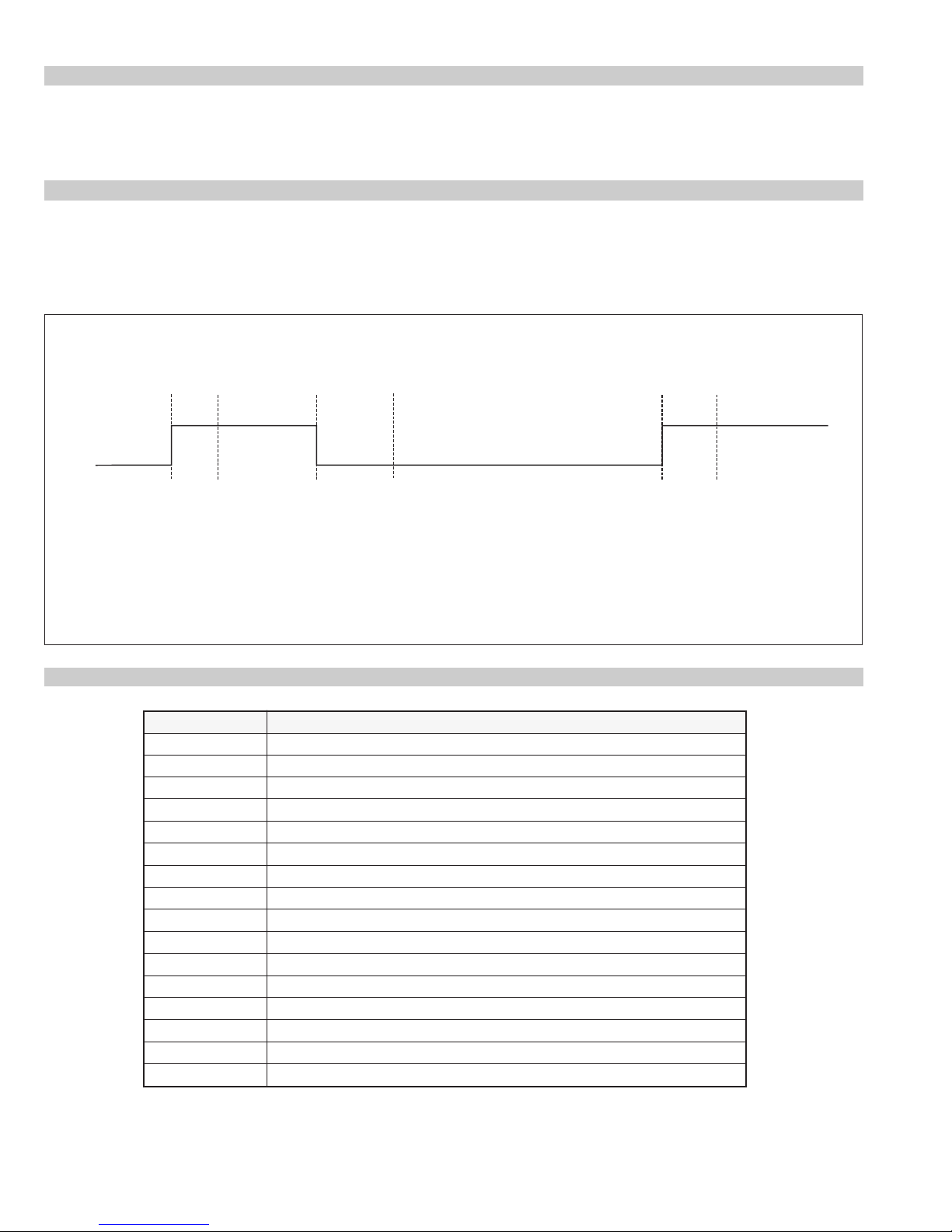
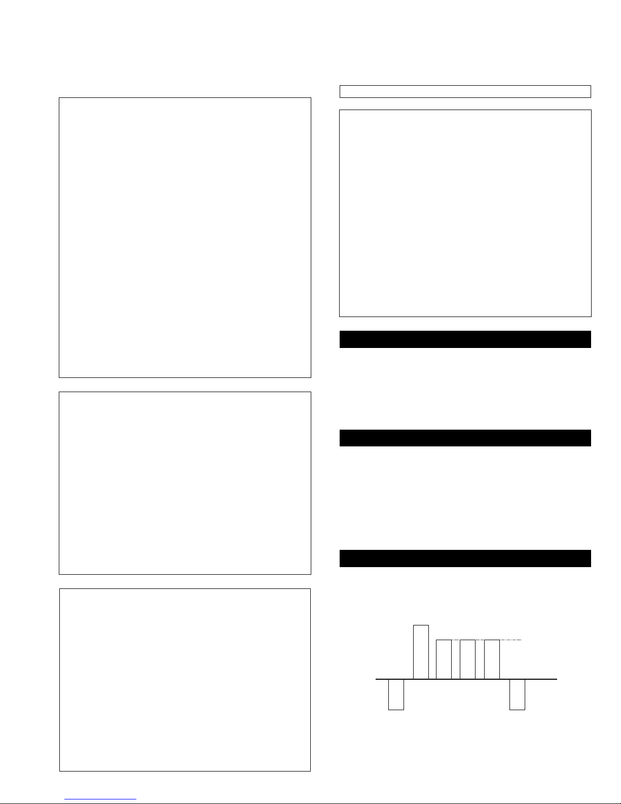
AKB Error (Error 5):
Once every main loop the micro checks the AKB stability by reading the IKR return from the Jungle IC. IKR=1 means that the AKB is stable,
IKR=0 means that the AKB is unstable. If the AKB status is unstable for 10 seconds, an AKB error is diagnosed. AKB stability is not checked
during the first 20 seconds after AC switch on.
If this error is diagnosed, the r espective NVM r egister will be updated and the r esponse LED will flash 5 times continually, but the set will not go
into standby mode. If the AKB status becomes stable, and remains stable for 10 seconds, the LED will stop flashing.
Time / seconds
10090807050 60403020100
IKR
Return
BCD EF
A
A. IKR Return first goes high after 12 seconds.
B. Micro begins checking IKR Return status 20 seconds after power on.
C. Micro detects IKR return = 0.
D. Micro detects that IKR has been 0 for 10 seconds; NVM counter is incremented and the LED
starts flashing (flashes 5 times, off for 2 seconds, flashes 5 times, etc.
E. Micro detects that IKR=1; LED continues to flash.
F. Micro detects that IKR has been high for 10 seconds; LED stops flashing.
Startup Diagnostic Errors (Errors 6-18, 27, 29-32):
MVN noitpircseDrorrE
6wolnipLCS
7wolnipADS
8wolerasnipADSehtdnaLCShtoB
9)6702AXC(elgnujehtmorfegdelwonkcaoN
01)0402AXC(hctiwsoedivehtmorfegdelwonkcaoN
11renutehtmorfegdelwonkcaoN
21PSMehtmorfegdelwonkcaoN
31MVNehtmorfegdelwonkcaoN
41hctiwsoediv9802AXCehtmorfegdelwonkcaoN
61 rednapxEtroPoediv5781AXCehtmorfegdelwonkcaoN
81 )0708AXC(ecnegrevnoCcimanyDehtmorfegdelwonkcaoN
72.tsetMARtxeTtcapmoCretfawolnipDXT_L3M
92woLniPDXT_L3M
03woLniPDXR_L3M
13woLniPNEL3M
23liaftsetMARtxeTtcapmoC
If any of these errors are detected, the r espective NVM register will be incremented. The software will then carry on with the power up sequence.
6
General IIC Device Run-time Errors (Errors 19-23):
MVN noitpircseDrorrE
91 esilaitiniotgnitpmettanehwelgnujehtmorfegdelwonkcaoN
02 sretsigerdaerotgnitpmettanehwelgnujehtmorfegdelwonkcaoN
12noitasilaitinignirudteseretelpmoctonnachctiwSVA
22 sretsigerdaerotgnitpmettanehwhctiwSVAmorfegdelwonkcaoN
32 etirwrodaerotgnitpmettanehwMVNehtmorfegdelwonkcaoN
If any of these errors are detected, the r espective NVM register will be incremented and the software will carry on.
Compact Text Run-time Errors (Errors 26, 28, 33 & 34):
MVN noitpircseDrorrE
62
82
33 .secivedfonoitasilaitinigniruddeliaftsetMARtxeTtcapmoC
.)elbissop
.)elbissop
sawnoitacinummocontahtseilpmi(18retsigergnikcehcnehwwolnipDXT_L3M
sawnoitacinummocontahtseilpmi(esilaitiniotgnitpmettanehwwolnipDXT_L3M
In the case of these errors, the ‘device reset’ pin will be held low for 60ms, causing a hardwar e r eset of Compact Text. Following this reset, a longer
timeout will be allowed for the M3L bus to recover. If the error still exists, the NVM register will be incr emented and the sof twar e will carry on.
MVN noitpircseDrorrE
43
.)detpurrocemocebroteser
rehtiesahtxeTtcapmoCtahtseilpmi(hgihnipDXT_L3Mtub,liafkcehc18retsigeR
MSP and DSP Run-time Errors (Errors 24 & 25):
MVN noitpircseDrorrE
:gniwollofehtfoynaybdesuacebnac42rorrE
42
.)detpurrocemoceb
52
.)detpurroc
.)detpurrocemocebroteserrehtiesah
.noitcurtsniteseregdelwonkcaotsliafPSM-
PSMehttahtseilpmi(liafkcehcretsigeRelacserPtracS,noitasilaitiniPSMretfA-
roteserrehtiesahPSMehttahtseilpmi(liafkcehcretsigeRelacserPtracS-
emocebroteserrehtiesahPSMehttahtseilpmi(detpurrocetybtsetPSD
For both these errors, the software will refresh the MSP and DSP registers. If the errors still exist, the NVM counter will be incremented, and the
software will carry on.
7

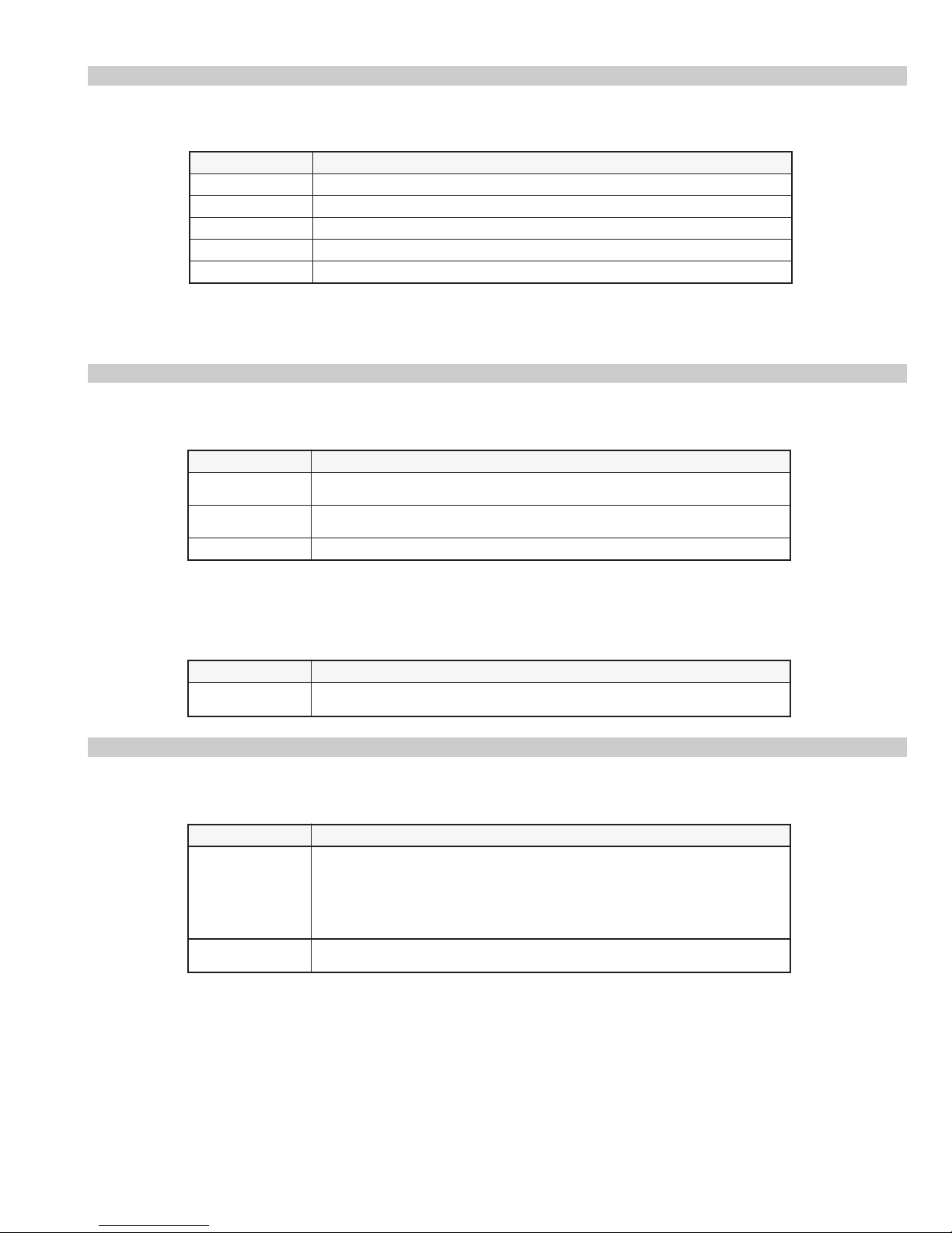
Error Display Mode
Error Display Mode is entered by the following sequence of commands :
Standby -> Information -> Digit 5 -> Volume Down -> TV
This mode will display a special menu, which will list all possible errors and the number of occurrances of each error
(0 - 255, as stored in the NVM). There will also be a display of the current error (0 if no error). This display mode
will appear as follows :
ERROR DISPLAY MODE
CURRENT ERROR CODE = 0
Error Code Times Error Code Times
2 0 19 0
3 0 20 0
4 0 21 0
5 0 22 0
6 0 23 0
7 0 24 0
8 0 25 0
9 0 26 0
10 0 27 0
11 0 28 0
12 23 29 0
13 0 30 0
14 0 31 0
15 0 32 0
16 0 33 0
17 0 34 0
18 1
Whilst in this mode, the number of occurences of each error can be reset to 0 by following sequence of Sircs commands: Digit 8 -> Digit 0.
‘TT08’ will also reset this NVM data.
This mode can only be exited by switching off the TV.
The Current Error Code can also be read by using a TV Error Reader (IIC slave address 42H). This device simply receives 1 data byte, which is the
error number in binary coded decimal form.
8
SECTION 1 GENERAL
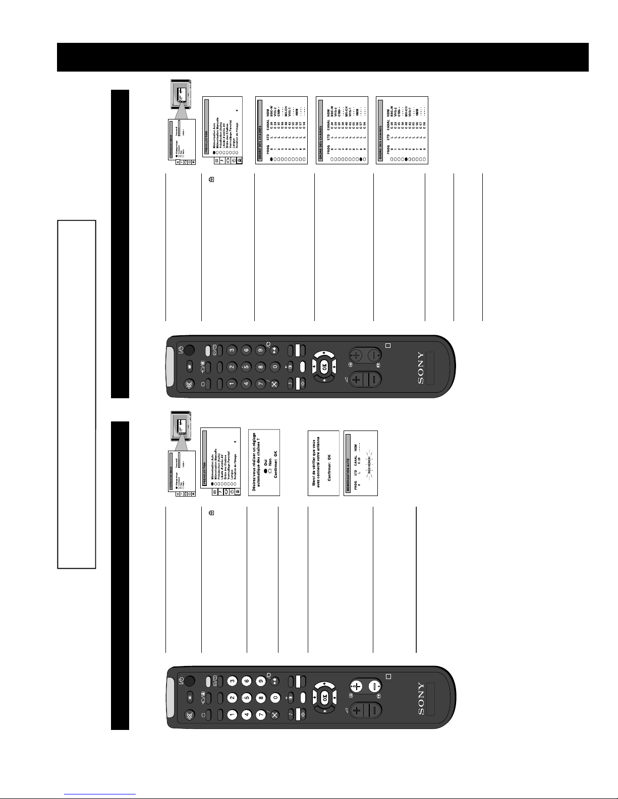
Additional TV Features
Re-arranging the TV channels
After tuning the TV, you can use this feature to change the analogue channel order.
1. Press the MENU button on the remote control to display
. . . .. . . . .
. . . .. . . . .
the menu on the TV screen.
button to
b
button on the remote control to select the
v
symbol on the menu screen then press the
2. Press the
E
TV/SAT
D
AB
C
11
buttons to select the channel you want
PILOTE PROGR
MENU
v
or
V
4. Press the
to move then press the OK button to confirm.
PROGR
button to select ‘Ordre des Chaînes’ then
button to enter the ‘ORDRE DES CHAINES’
v
b
enter the ‘PRESELECTION’ menu.
press the
menu.
3. Press the
SAM
SORTIE
VEN
SOIREE
JEU
LUN MAR MER
DIM JOURNEE NUIT
PREFER -/--
SERV PERSO
buttons to select the new programme
v
or
V
position (eg PROG 4) for your selected channel then
5. Press the
R
RM-931
press the OK button to confirm. The channel you selected
in step 4 now moves to its new programme position.
TV
6. Repeat steps 4 and 5 if you wish to sort other channels.
screen.
7. Press the MENU button to remove the menu from the TV
The operating instructions mentioned here are partial abstracts from the ‘Operating
Instruction Manual’. The page numbers of the ‘Operating Instruction Manual’ remain
as in the manual.
Additional TV Features
Automatically tuning the TV
You have already tuned in all available channels using the ‘Automatically tuning the TV’ section at the start of this manual. If
you need to repeat the tuning procedure however, follow the instructions below and the TV automatically searches and stores all
. . . .. . . . .
. . . .. . . . .
button to
b
button to select ‘Mémorisation Auto’
v
button on the remote control to select the
v
the menu on the TV screen.
1. Press the MENU button on the remote control to display
symbol on the menu screen then press the
2. Press the
E
TV/SAT
D
AB
C
LUN MAR MER
or
V
enter the ‘PRESELECTION’’ menu.
3. Press the
SAM
VEN
JEU
DIM JOURNEE NUIT
available analogue TV channels for you.
button to display the autotune menu.
b
then press the
SORTIE
SOIREE
PREFER -/--
buttons to select ‘Oui’ then press the
v
or
V
4. Press the
SERV PERSO
OK button to con firm.
PILOTE PROGR
MENU
5. A new menu appears asking you to check that the
antenna is connected. Ensure the antenna is connected
then press the OK button to confirm. The TV now starts
to automatically search and store all available channels
for you. Please be patient and do not press any buttons
once this search and store operation has started.
menu disappears from the TV screen. Press the
PROGR+/- or the numbered buttons on the remote
6. When the automatic tuning procedure is complete, the
R
PROGR
RM-931
automatic tuning procedure.
control to view the TV channels.
Note: Press the MENU button if you wish to stop the
TV
10
9
. . . .. . . . .
. . . .. . . . .
. . . . . . . . .
13
. . . . . . . . .
buttons to adjust your selected item.
B
or
b
5. Press the
SORTIE
SOIREE
PREFER -/--
B
Headphones
i Volume
i Son Stereo Stereo b Mono (for a stereo broadcast)
(for a bilingual broadcast)
A for channel 1 b B for channel 2
(for a bilingual broadcast)
Jazz
Aigus
Graves
Rock
B Pop
button to return to the ‘CONTROLE DU SON’ menu.
7. If you selected ‘Réglage du Son’ in step 3, press the
PILOTE PROGR
8. Repeat steps 3-7 to adjust the other items.
MENU
9. Press the MENU button to remove the menu from the TV
screen.
Réglage du Son b Personnel
PROGR
Balance
R
RM-931
button to store the new setting.
6. As soon as you have adjusted the item, press the OK
SERV PERSO
stay the same
to the broadcast signal
B Off: volume level changes according
Raz Resets picture to factory preset levels
Effet Spatial b On: volume level of the channels will
A for channel 1 b B for channel 2
Son Sound Ster eo b Mono (for a stereo broadcast)
TV
adjusted over a range of -12 to +12.
Vol individuel The channel volume level c an be
button to confirm.
b
you wish to adjust then press the
E
D
C
or
V
button to confirm.
b
buttons to select the item on the screen you wish to
For a description of the menu items and their effects, see
the table below.
v
adjust then press the
4. If you selected ‘Réglage du Son’ in step 3, press the
SAM
VEN
JEU
LUN MAR MER
DIM JOURNEE NUIT
b
button on the remote control to select
buttons to select the item on the screen
v
v
or
or
V
V
the menu on the TV screen.
the symbol on the menu screen then press the
button to enter the ‘CONTROLE DU SON’ menu.
2. Press the
3. Press the
TV/SAT
AB
1. Press the MENU button on the remote control to display
Adjusting the sound
Additional TV Features
Although the sound is adjusted at the factory, you can modify it to suit your own taste.
. . . .. . . . .
Adjusting the picture
Additional TV Features
. . . .. . . . .
. . . .. . . . .
button to enter
b
button to confirm. For a
b
button to confirm.
buttons to select the item on the screen you
button on the remote control to select the
v
v
or
or
V
V
menu on the TV screen.
the ‘CONTROLE DE L’IMAGE’ menu.
description of the menu items and their effects, see the table
wish to adjust then press the
symbol on the menu screen then press the
2. Press the
3. Press the
E
TV/SAT
D
AB
C
1. Press the MENU button on the remote control to display the
Although the picture is adjusted at the factory, you can modify it to suit your own taste.
b
buttons to adjust your selected item.
B
or
b
buttons to select the item on the screen you wish to
v
or
below.
V
adjust then press the
4. If you selected ‘Réglage Image’ or ‘Ratio’ in step 3, press the
SAM
VEN
JEU
LUN MAR MER
DIM JOURNEE NUIT
5. Press the
6. As soon as you have adjusted the item, press the OK button to
SORTIE
SOIREE
PREFER -/--
button to return to the ‘CONTROLE DE L’IMAGE’ menu.
store the new setting.
B
8. Repeat steps 3-7 to adjust the other items.
7. If you selected ‘Réglage Image’ or ‘Ratio’ in step 3, press the
MENU
SERV PERSO
PILOTE PROGR
9. Press the MENU button to remove the menu from the TV
screen.
Cinéma (for films)
B Concert (for live broadcasts)
buttons to select the desired mode.
v
Teinte**
Couleurs*
Netteté*
Luminosité*
Réglage Image Réglage Image b Personnel (for individual settings)
PROGR
Contraste
Raz Resets picture to factory preset leve ls
R
RM-931
Haut/Bas 0
Auto 16:9 b Non b Oui
Ratio Ratio (refer to page 14 for details)
** Available for NTSC colour system only.
*Only if you select ‘Personnel’ in ‘Réglage Image’.
‘CONTROLE DU SON’ menu screens.
Changing picture and sound modes quickly
You can quickly change the Picture Mode or the Equalizer Mode
without entering the ‘CONTROLE DE L’IMAGE’ or the
or
V
or the symbol for equalizer modes.
2. Press the
screen.
3. Press the OK button to remove the display from the TV
1. Press the symbol on the remote control for picture modes
TV
12
10
. . . .. . . . .
. . . .. . . . .
button to enter the
b
buttons to adjust the picture rotation.
button to select the symbol on the menu
v
button to select ‘Rotation de l’image’ then
v
B
or
button to highlight the 0 (zero) on the right
b
b
Additional TV Features
Adjusting the picture rotation
If, due to the earth’s magnetic field, the picture slants, you can use this feature to readjust the picture.
1. Press the MENU button on the remote control to display
. . . .. . . . .
‘PRESELECTION’ menu.
the menu on the TV screen.
screen then press the
2. Press the
E
TV/SAT
D
AB
C
LUN MAR MER
. . . .. . . . .
press the
of the menu.
3. Press the
SAM
SORTIE
VEN
SOIREE
JEU
DIM JOURNEE NUIT
PREFER -/--
SERV PERSO
The adjusting range is -5 to +5.
4. Press the
MENU
PILOTE PROGR
TV screen.
5. Press the OK button to store the new range.
6. Press the MENU button to remove the menu from the
R
PROGR
RM-931
TV
16
15
button repeatedly
b
button to enter the
b
button to select the symbol on the menu
v
the menu on the TV screen.
1. Press the MENU button on the remote control to display
Using the Further Programme Preset feature
Additional TV Features
With this feature you can manually fine-tune the TV to obtain a better picture reception if the picture is distorted.
screen then press the
2. Press the
E
TV/SAT
D
AB
C
‘PRESELECTION’ menu.
LUN MAR MER
buttons to select the relevant
PILOTE PROGR
MENU
v
or
V
4. Press the
button to select ‘présélection (suite)’ then
button to enter the ‘PRESELECTION
v
b
(SUITE)’ menu.
press the
3. Press the
SAM
SORTIE
VEN
SOIREE
JEU
DIM JOURNEE NUIT
PREFER -/--
SERV PERSO
buttons to fine tune the channel
v
or
V
programme number then press the
frequency over a range of -15 to +15. Press the OK
to select AFT column.
button to confirm. Repeat steps 4 and 5 if you wish to
5. Press the
PROGR
fine tune other channels.
TV screen.
6. Press the MENU button to remove the menu from the
R
RM-931
TV
11

. . . .. . . . .
. . . .. . . . .
button to enter the
b
button to select the symbol on the TV
v
19
v
or
buttons to search for the next available
v
or
V
V
button to
b
button to enter the
b
button to confirm.
b
buttons to select an unused programme
v
button to se lect ‘Mémorisation Manuelle’ on
v
or
V
buttons to select the TV broadcast
v
or
V
button to confirm.
b
buttons to select C for terrestrial
v
or
V
Additional TV Features
Manually tuning the TV
You have already tuned the TV automatically using the instructions at the start of this manual. You can however carry out this
tuning operation manually, adding analogue channels to the TV, one at a time.
1. Press the MENU button on the remote control to display
. . . .. . . . .
. . . .. . . . .
the menu on the TV screen.
screen then press the
2. Press the
E
TV/SAT
D
AB
C
button
b
‘MEMORISATION MANUELLE’ menu.
‘PRESELECTION’ menu.
the menu screen then press the
3. Press the
SAM
SORTIE
VEN
SOIREE
JEU
LUN MAR MER
DIM JOURNEE NUIT
PREFER -/--
SERV PERSO
MENU
PILOTE PROGR
enter.
number for your channel then press the
4. Press the
PROGR
5. Press the
system (I for UK, L for France or B/G for Western
European countries) or a video input source (AV1,
AV2 ...) then press the
channels or S for cable channels in the ‘CANAL’
6. Press the
R
RM-931
column, then press the
7. Select the first number digit of ‘CANAL’ (channel) then
buttons on the remote controlorPress the
the second number digit of ‘CANAL’ with the number
TV
channel.
programme number you selected, press the
8. If you do not wish to store this channel on the
button.
press the MENU button to remove the menu from the
buttons on the remote control to continue searching for
the desired channel.
9. If this is the channel you wish to store, press the OK
TV screen.
10.Repeat steps 4-9 if you wish to store more channels then
17
button on the remote control to select the
v
symbol on the menu screen then press the
the menu on the TV screen.
1. Press the MENU button on the remote control to display
Using the parental lock
Additional TV Features
This feature enables you to prevent undesirable broadcasts appearing on the TV.
2. Press the
E
TV/SAT
D
AB
C
LUN MAR MER
to enter the ‘PRESELECTION’ menu.
symbol appears before the
button to select ‘Verrouillage Parental’ then
button to enter the ‘VERROUILLAGE
v
b
press the
PARENTA L’ menu.
3. Press the
SAM
SORTIE
VEN
SOIREE
JEU
DIM JOURNEE NUIT
PREFER -/--
SERV PERSO
PILOTE PROGR
MENU
button to select the channel you wish to
v
4. Press the
block then press the OK button to confirm your
selection. The
programme position to indicate this channel is now
blocked. To unblock the channel, press the OK button
again. The symbol disappears.
5. Repeat step 4 if you wish to block other chan nels.
PROGR
TV screen.
6. Press the MENU button to remove the menu from the
R
RM-931
TV
12
25
TELETEXT
153
101
98
TELETEXT
Index
Programme
News
Sport
Weather
25
153
TELETEXT
Index
Programme
News
25
153
101
98
TELETEXT
Index
Programme
News
Sport
Weather
101
98
Sport
Weather
25
153
101
TELETEXT
Index
Programme
News
Sport
98
Weather
Additional TV Features
Teletext
the channel which carries the teletext service you wish
signals are weak.
to receive.
teletext.
buttons on the remote control. If you make a mistake,
complete the number then re-enter the correct page
Switching Teletext on and off
1. Press a numbered button on the remote control to select
E
TV/SAT
D
AB
C
2. Press the button on the remote control to switch on
SAM
VEN
JEU
LUN MAR MER
Teletext is an information service transmitted by most TV stations.
. . . .. . . . .
. . . .. . . . .
button
b
3. Select the required page number using the numbered
DIM JOURNEE NUIT
SORTIE
SOIREE
PREFER -/--
number.
4. Press the button to switch off teletext.
SERV PERSO
Note: Teletext errors may occur if the broadcasting
MENU
PILOTE PROGR
Using Other Teletext Functions
PROGR
To superimpose Teletext on to the TV
Press the button on the remote control once if in teletext
mode or twice if in TV mode to superimpose teletext on to
the TV picture. Press the button once more to cancel.
To move to the next or preceding page
Press the or buttons to select the previous or next
R
RM-931
page.
TV
To freeze a Teletext page
Press the button to freeze the page. Press again to cancel
the freeze.
Revealing concealed information ( eg:answer s to a
quiz).
Press the button to reveal information. Press again to
conceal the information.
Using colour buttons to access pages (Fastext)
(only available if the TV station broadcasts Fastext signals)
When the colour coded menu appears at the bottom of a
page, press the colour button (green, red, yellow or blue) on
the control to access the corresponding page.
22
button to
b
button on the remote control to select the
v
symbol on the menu screen then press the
the menu on the TV screen.
1. Press the MENU button on the remote control to display
Skipping programme positions
Additional TV Features
This function enables you to skip unused programme positions when selecting them with the PROGR+/- buttons. However, by
using the number buttons you can still select the skipped programme position.
2. Press the
E
TV/SAT
D
AB
C
to enter the ‘PRESELECTION’ menu.
LUN MAR MER
PILOTE PROGR
MENU
buttons to select the programme
v
or
V
4. Press the
button to select ‘---’ then press the OK
v
position you want to skip then press the
enter the ‘STD’ column.
PROGR
5. Press the
button to store.
6. Repeat steps 4 and 5 to skip other programme positions.
R
RM-931
TV screen.
7. Press the MENU button to remove the menu from the
TV
button to enter the ‘MEMORISATION
b
button to select ‘Mémorisation Manuelle’
v
MANUELLE’ menu.
then press the
3. Press the
SAM
SORTIE
VEN
SOIREE
JEU
DIM JOURNEE NUIT
PREFER -/--
SERV PERSO
20
13
Selecting the output source for the
. . . .. . . . .
. . . .. . . . .
H
or
G
scart socket
2
s
2
button to confirm.
b
button to enter the ‘CONNEXION
b
buttons to select the desired source (see
button to select the symbol on the menu
v
the menu on the TV screen.
1. Press the MENU button on the remote control to display
screen then press the
2. Press the
button to highlight ‘Ecran TV’ (input source
v
VIDEO’ menu screen.
3. Press the
B
or
b
3
or socket) then press the
for the TV screen) or ‘Sortie’(output source for /
below) then press the OK button to confirm:
TV Screen TV, AV1, RGB, AV2, YC2, AV3, SAT
4. Press the
Output TV, AV1, AV2, YC2, AV3, SAT, AUTO
screen.
5. Press the MENU button to remove the menu from the TV
E
TV/SAT
Connecting equipment to the TV
Optional Equipment
AB
P
__
++
2
MONO
L/G/S/I R/D/D/D
2
s
SAM
SORTIE
D
VEN
SOIREE
C
JEU
LUN MAR MER
DIM JOURNEE NUIT
PREFER -/--
8mm/Hi8
camcorder
P
__
++
MONO
2
L/G/S/I R/D/D/D
2
s
D
C
B
SERV PERSO
MENU
PILOTE PROGR
S-VHS/Hi8
camcorder
PROGR
A
G
G
F
F
H
G
D
C
B
R
RM-931
SORTIE
AUDIO
NUMERIQUE
OPTIQUE
TV
24
5V 200mA
I J
H
5V 200mA
MODEM
3
G
2
S
2
1
L/G/S/I
R/D/D/D
F
E
MODEM
3
SORTIE
AUDIO
NUMERIQUE
OPTIQUE
2
S
2
1
L/G/S/I
R/D/D/D
Modem
Telephone
socket
Hi-Fi
VCR
DAT
player
2
1
PlayStation
23
2
EE
D
D
H
J
• Audio/video input signal through the scart connector
• RGB input signal through the scart connector
Connecting equipment to the TV
Optional Equipment
Using the following instructions, you can connect a wide range of optional equipment to your TV.
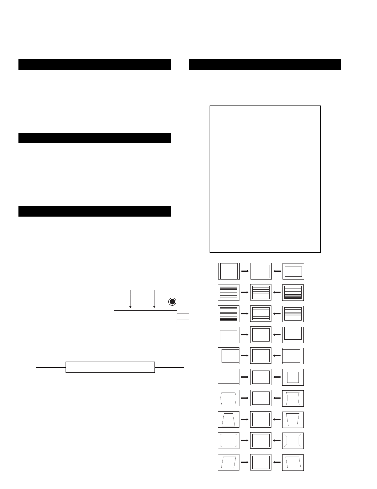
Connecting equipment to the TV
1. Connect your equipment to the correct TV socket (as shown in the diagram).
for your equipment appears on the TV screen:
2. Press the button repeatedly on the remote control until the correct input symbol
Symbol Input signals
1
B
C
phono sockets and
phono sockets and
• Audio/video in put signal through the scart connector or the
• S video inpu t sig nal through the scart connector or the
• Audio/video input signal through the scart connector
4. To return to the normal TV picture, press the button on the remote control.
Note: To avoid picture distortion, do not connect equipment to the , , and
sockets at the same time.
Additional information when connecting equipment
Connecting a VCR
tune in the VCR signal to TV programme number ’0’.
We recommend you connect your VCR to the socket using a scart lead. If you do not
have a scart lead, use the ‘Manually Tuning the TV’ section of this instruction manual to
3
2
3
2
s
3. Switch on the connected equipment.
A
A
Connecting headphones
Plug in your headphones to the socket on the front of the TV set.
Connecting to external audio equipment
EE
manual).
For mono equipment
Plug in your hi-fi equipment to the sockets on the rear of the TV if you wish to amplify
the audio output from the TV. The output level from the sockets can be varied by
Connect the phono plug to the L/G/S/I socket on the front of the TV and select the
adjusting the volume of the headphones (refer to the ‘Adjusting the sound’ section of this
I
section of this manual and select ‘A’ on the sound menu screen.
For DAT players
Connect to the digial audio socket on the rear of the TV.
Connecting a modem
Connect the modem unit to the connection on the rear of the TV and your telephone
input signal using the instructions on this page. Finally, refer to the ‘Adjusting the sound’
socket.
14
Additional Information
Troubleshooting
/
button on the remote control.
using the button on the front of the TV.
display. Adjust the brightness, picture and colour balance
levels.
the factory settings.
the RGB symbol is displayed on the screen.
remote control.
display and adjust the colour setting.
the factory settings.
the rear of the TV.
TV/SAT b utton until it lights up green for TV mode or red for
• Press the button on the front of the TV.
• If the indicator is on press the button or a numbered
• Check the aerial or satellite connection.
• Turn the TV off for 3 or 4 seconds and then turn it on again
• Using the MENU system, select the Control de l’image
• From the Control de l’image display select Raz to return to
• Press the button repeatedly on the remote control until
• Press the button on the remote control.
• If is displayed on the screen, press the button on the
Problem Solution
Here are some simple solutions to problems which may affect the picture and sound.
No picture (screen is dark), no sound • Plug the TV in.
Poor or no picture (screen is dark), but
good sound.
Poor picture quality when watching
an RGB video source.
Good picture, no sound
No colour on colour programmes • Using the MENU system, select the Control de l’image
• From the Picture Adjustment display select Raz to return to
• Turn off any equipment connected to the scart connectors on
Distorted picture when changing
programmes or selecting T elet ext
SAT mode.
• Check the remote control is in the correct mode. Press the
• Contact your nearest Sony service centre.
Remote control does not function • Replace the batteries.
The standby indicat or on the TV
flashes
• If you continue to have these problems, have your TV serviced by qualified personnel.
• NEVER open the casing yourself.
28
Specifications
Additional Information
TV system
L, B/G/H, I, DK
Colour system
PAL, SECAM
NTSC 3.58, 4.43 (only Video In)
MPEG 2
Channel coverage
See ‘Receivable Channels’ on the next page.
21-pin Euro connector (CENELEC standard) including audio/video
Audio outputs - phono jacks
One optical digital audio output socket
Video input -phono jacks
Audio inputs - phono jacks
S video input - 4 pin DIN
21-pin Euro connector (CENELEC standard) including audio/video
input, RGB input, TV audio/video output.
input, S-video in put, Monitor audio/video output.
input, selectable audi o/video output.
2
s
/ 21-pin Euro connector (CENELEC standard) including audio/video
3
2
Picture tube
1
FD Trinitron WIDE
Approx 71cm (28inches) (Approx 66cm picture measured diagonally), 102° deflection
Rear Terminals
Headphones jack - minijack stereo
123W
Approx. 761x496x525mm
2
2
s
Front Terminals
Sound output
Left/Right: 2x20W (music power)
Sub woofer: 20W (music power)
Power consumption
Approx. 45.0kg
Dimensions (wxhxd)
Weight
Accessories supplied
RM-931 remote control (1)
IEC designated size AA battery (2)
V.23 MODEM
Other features
Teletext
Design and specifications are subject to change without notice.
26
15
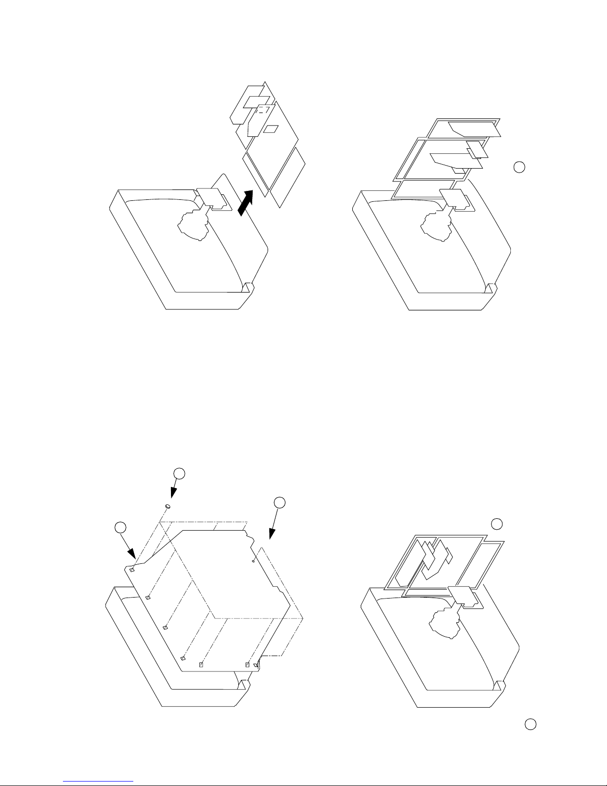
1 Clip bracket into Beznet
SECTION 2
DISASSEMBLY
2-2. CHASSIS ASSY REMOVAL
2 8 Screws
(BTVTP 4x16)
1 1 Screw (BTVP 4x16)
3 Rear Cover
2-3-2. SERVICE POSITION (2) 2-3-1. SERVICE POSITION (1)
2 Insert into heatsink
2-1. REAR COVER REMOVAL
1 Snap off from main bracket
16

A Board
1 Remove CN301 before removing A board
2-5. A BOARD REMOVAL
A board
2-6. A EXTENSION BOARD
BE-3E Extension Board
2-4. WIRE DRESSING
17
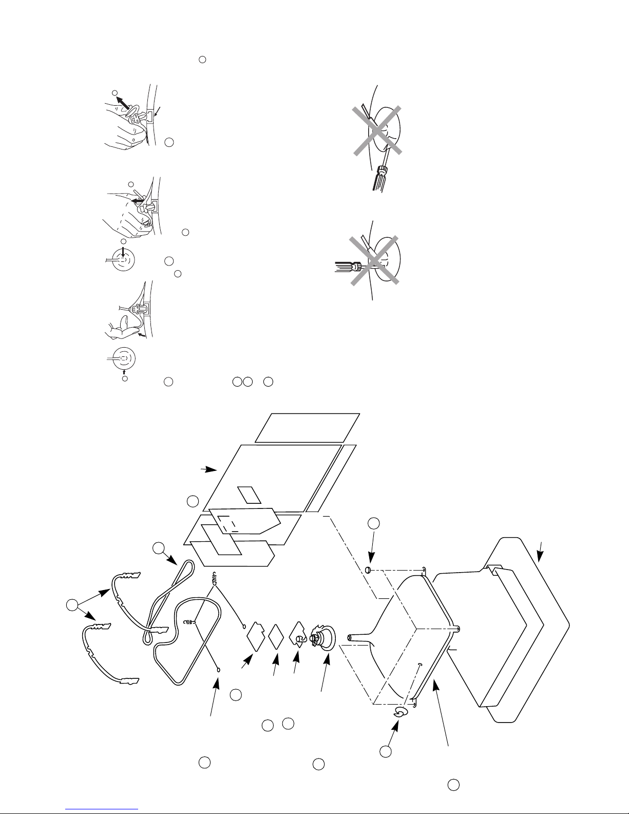
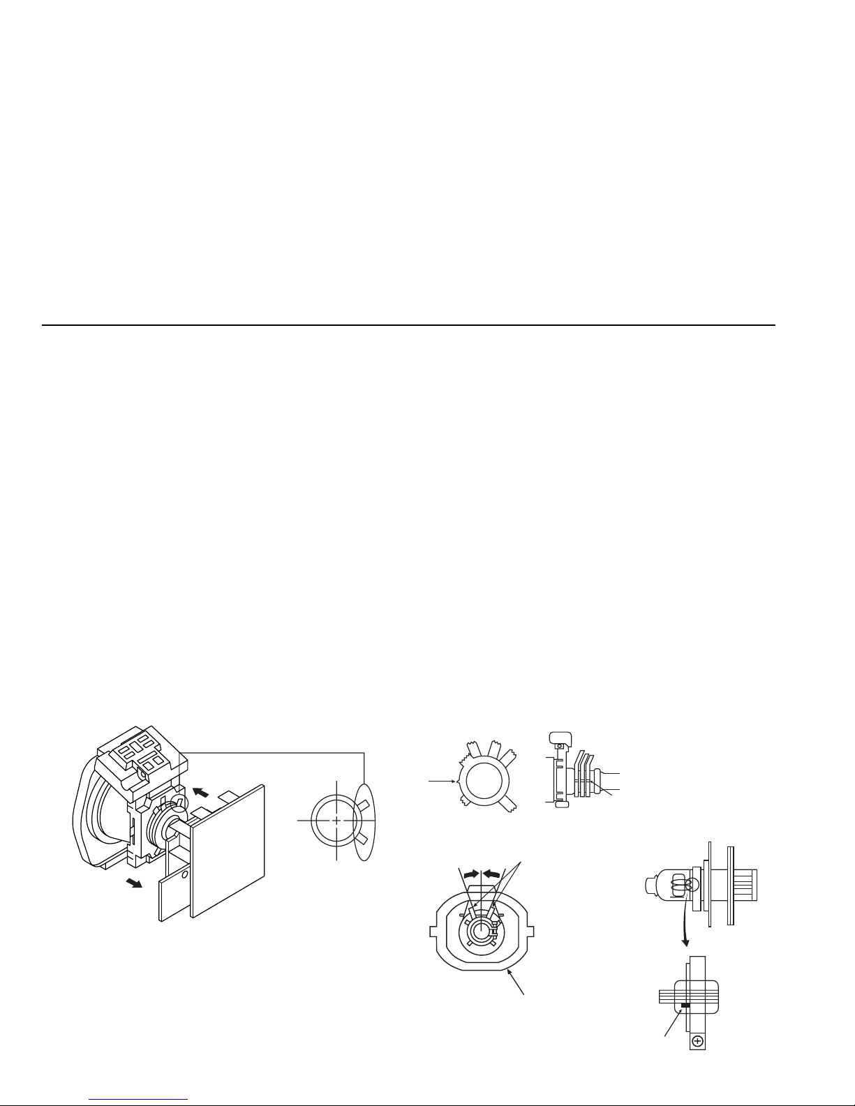
• REMOVAL OF ANODE-CAP
c
b
a
Note : Short circuit the anode of the picture tub e and the anode cap to the metal chassis, CRT
* REMOVING PROCEDURES.
shield or carbon paint on the CRT, after removing the anode.
Anode button
3 When one side of the rubber cap is
separated from the anode button, the
anode-cap can be removed by turning
up the rubber cap and pulling it up in
the direction of the arrow c
b
2 Using a thumb pull up the rubber cap
firmly in the direction indicated by the
arrow b
anode connector.
Do not turn the rubber foot over excessively this may cau s e da mage if the shatter
hook sticks out.
Turn up one side of the rubber cap in
the direction indicated by the arrow a
1
• HOW TO HANDLE THE ANODE-CAP
1 To prevent damaging the surface of the anode-cap do not use sharp mate rials.
2 Do not apply too great a pressure on the rubber, as this may cause damage to the
3 A m et al fitting called a shatter hook t erm inal is fitted inside the rubber cap.
2 Chassis assy
8 Degaussing coils
7 DGC holders
2-7. PICTURE TUBE REMOVAL
9 Spring Extension
3 C board
10 Four PT screws
5 Neck assy
4 VM Board
Anode cap
6 Deflection yoke
1
Cushion
11 Picture tube
18
19
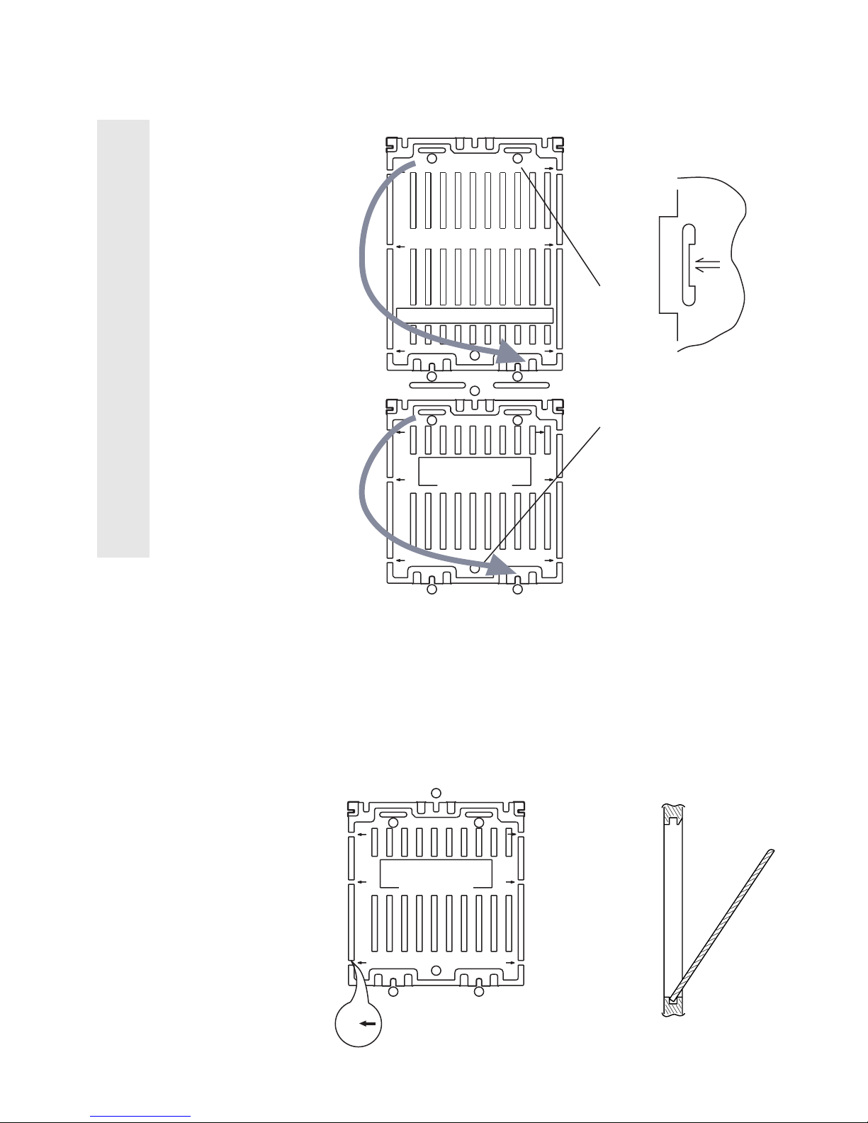
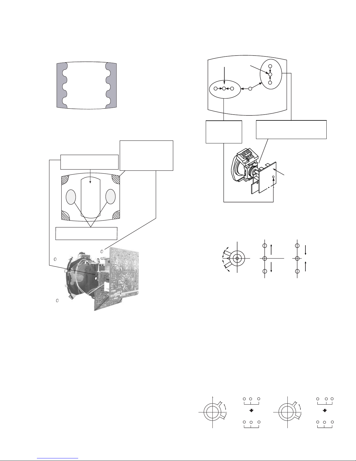
Fig 2
NUMERICAL MARKINGS
ATTENTIONATTENTION
THIS PLATE MUST BE REMOVED
(TURN 180' NOT FLIP OVER)
AFTER CUTTING AWAY
FOR SAFETY REASONS
THIS PLATE MUST BE REMOVED
AFTER CUTTING AWAY FOR THE SAFETY REASON.
22
2
2
1
1
44
3
4
4
REFITTING REFITTING
ATTENTIONATTENTION
THIS PLATE MUST BE REMOVED
(TURN 180' NOT FLIP OVER)
AFTER CUTTING AWAY
FOR SAFETY REASONS
22
2
2
1
1
Cut points
Fig 1
MAIN BRACKET
INSERT FROM
THE BOTTOM
SIDE
FIG 3
Fig 4
REMOVAL AND REPLACEMENT OF THE MAIN-BRACKET
BOTTOM PLATES.
(1) REMOVING THE PLATES
In the event of servicing being required to the solder side of the D Board printed
wiring board, the bottom plates fitted to the main chassis bracket require to be
removed.
This is performed by cutting the gates with a sharp wire cutter at the locations
indicated by arrows.
Note :There are 4 plates fitted to the main br acket and secured by 6 gates.
Only remove the necessary plate to gain access to the printed wiring board.
(2) REFITTING THE PLATES
Because the plates differ in size it is important that the correct plates are refitted in
their original location.
The plates are identified by numerical markings on their top side e.g. 1,2
1. Identify the plate by locating its marking.
2. Rotate the plate through 180’ (do not flip over).
3. Locate the corresponding numerical markings indicated on the main
chassis. See Fig 2.
4. Refit the plate as indicated in Fig 3 with the markings located next to each
other.
£
For safety reasons, on no account should the plates be
removed and not refitted after servicing.
In the event of the plates requiring to be removed
at a later stage, this can be achieved by inserting a
screwdriver in the snap-recess indicated as in Fig 4
and lifting out.
20
• When complete readjustment is necessary or a new
picture tube is installed, carry out the following
adjustments.
• Unless there are specific instructions to the contrary,
carry out these adjustments with the rated power supply.
• Unless there are specific instructions to the contrary, set the
controls and switches to the following settings:
Contrast ............... normal
Brightness ............... normal
Carry out the following adjustments in this order:
3-1. Beam Landing
3-2. Convergence
3-3. Focus
3-4. White balance
Note: Test equipment required
1. Color bar/pattern generator.
2. Degausser.
3. Digital multimeter.
4. Oscilloscope.
SECTION 3
SET-UP ADJUSTMENTS
Fig.3-1
Fig.3-2
Purity
Align Pips
on each
magnet
Neck a s sy
Align the bottom edge
of the neck assy with
the G3 hole centre.
Deflection yoke
3-1.BEAM LANDING
Preparation:
1. In order to reduce the influence of geomagnetism on the set’s
picture tube, face it in an easterly or westerly direction.
2. Switch on the set’s power and degauss with the
degausser.
(1) Adjustment of Correction Magnet for Y-Splitting
Axis
1. Input a crosshatch signal from the pattern generator.
2. Set the Picture control to minimum and confirm that the
Brightness control is set to normal.
3. Position the neck assembly as indicated in Fig.3-2.
4. Move the deflection yoke as far forward as is possible.
5. Adjust the upper and lower pin symmetrically by ope ning or
closing the Y-splitting axis correction magnets located on the
neck assembly.
6. Return the deflection yoke to its original position.
Caution :
High voltages are present on the Deflection yoke termin als take care when handling the Deflection yoke whilst carrying
out adjustments.
(2) Landing
Note :Before carrying out the following adjustments
adjust the magnets as indicated below [See Fig.3-3].
1. Input an all-white signal from the pattern generator.
Maximize the picture sett in g and adjust the Brightness
setting.
2. Rough-adjust the focus and horizontal convergence.
3. Loosen the deflection yoke screws and align the purity
adjustment knob to its central position. [See Fig.3-1].
4. Switch from the all-white pattern to an all-green pattern.
5. Move the deflection yoke backwards and adjust with the
purity magnet so that the green is at the centre and it aligns
symmetrically. [See Fig.3-4].
6. Mov e the deflection yoke forward and adjust so that the
entire screen becomes green.
7. Switch the raster signal to red, then to blue and verify the
landing condition.
8. Wh en th e posi tion of th e def lec tion y oke h as b een de term ined ,
fasten the deflection yoke with the screw.
9. If the beam does not land correctly in all the corners of the
screen, use magnets to correct it. [See Fig.3-5].
Y-splitting axis correction magnet
Fig.3-3
21
HMC correction(A) HMC correction(B)
A < B
A = B
RG B
RG B
A > B
A = B
RGB
RG B
Fig.3-4
Fig. 3-5
3-2.CONVERGENCE
(1) Screen centre convergence
[Static convergence]
1. Input a dot signal from the pattern generator.
2. Normalize the picture setting.
3. [Moving vertically], adjust the V.STAT magnet so that the
vertical red, green and blue dots coincide at the centre of the
screen.
By opening or closi ng the V.S TAT magnet, the red, green and
blue dots move as indicated below.
Note: Do not adjust the H.STAT by rotating the V.STAT
magnets as this can affect the focus setting.
4. Correction for HMC [horizontal mis-convergence] and
VMC [vertical mis-convergence] by using the BMC
[Hexapole] magnet.
a). HMC correction by BMC [Hexapole] magnet and movement
of the electron beam.
Purity control corrects
this area
Disk magnets or
rotatable disk
magnets correct
these areas (a-d)
Deflection yoke positioning
corrects these areas
a
cd
b
Disk Magnets
H.STAT
convergence
control
V.STAT
vertical static magnet
Center dot
H.STAT VR on
mount side
H.STAT convergence
B
G
R
B
G
R
GREEN
BLUE
RED

22
b). VMC correction by BMC [Hexapole] magnet and movement
of the elect ron beam.
HAMP
6. HTIL correction can be performed by adding a THL correction
ASSY to the DY.
TLH correction Assy
4-057-714-01
HTIL
Fig 3-6
Note : If you are unabl e to ad j ust the corner conve rgence
properly, this can be corrected with the use of
permalloys.
C < D
C = D C > D C = D
R
G
B
C
D
C
D
R
G
B
R
G
B
R
G
B
VMC correction(A) VMC correction(B)
LAYOUT OF EACH CONTROL
Y-splitting axis correction magnet
V STAT convergence magnet
BMC (Hexaploe) magnet
Purity magnet
a-d: screen-corner
convergence defect
a
b
c
d
Permalloy Assy
X-4387-214-1
Convergence adjustment with permalloy.
23
3-3.SCREEN (G2)
1. Input a dot signal from the pattern generator.
2. Set the Picture, Brightness and Colour to minimum.
3. Apply 175V DC from an external power supply to the
R, G and B cathodes of the CRT.
4. Whilst watching the picture, adjust [SCREEN G2] located on
the FBT [flyback transformer] to the point just before the
flyback return lines disappear.
3-4.FOCUS
1. Receive a television broadcast signal.
2. Normalise the picture setting.
3 Adjust the focus control located on the FBT [flyback
transformer] to obtain the best focus at the centre of the screen.
Bring only the centre area of the screen into focus, the
magenta-ring appears on the screen. In this case, adjust the
focus to optimize the screen uniformly.
3-5. WHITE BALANCE
1. Input an all white signal from the pattern generator.
2. Enter into the Service Mode.
3. Enter into the ‘Picture Adjustment’ service menu.
4. Select ‘Sub contrast’ and adjust to 7.
5. Select the ‘Green drive’ and adjust so that the white balance
becomes optimum.
6. Select the ‘Blue drive’ and adjust so that the white balance
becomes optimum.
7. Press the ‘TV’ button on the remote commander to return to
TV operation.
SCREEN G2 ADJUSTMENT
WHITE BALANCE ADJUSTMENT
FOCUS
SCREEN (G2)
24
SECTION 4
CIRCUIT ADJUSTMENTS
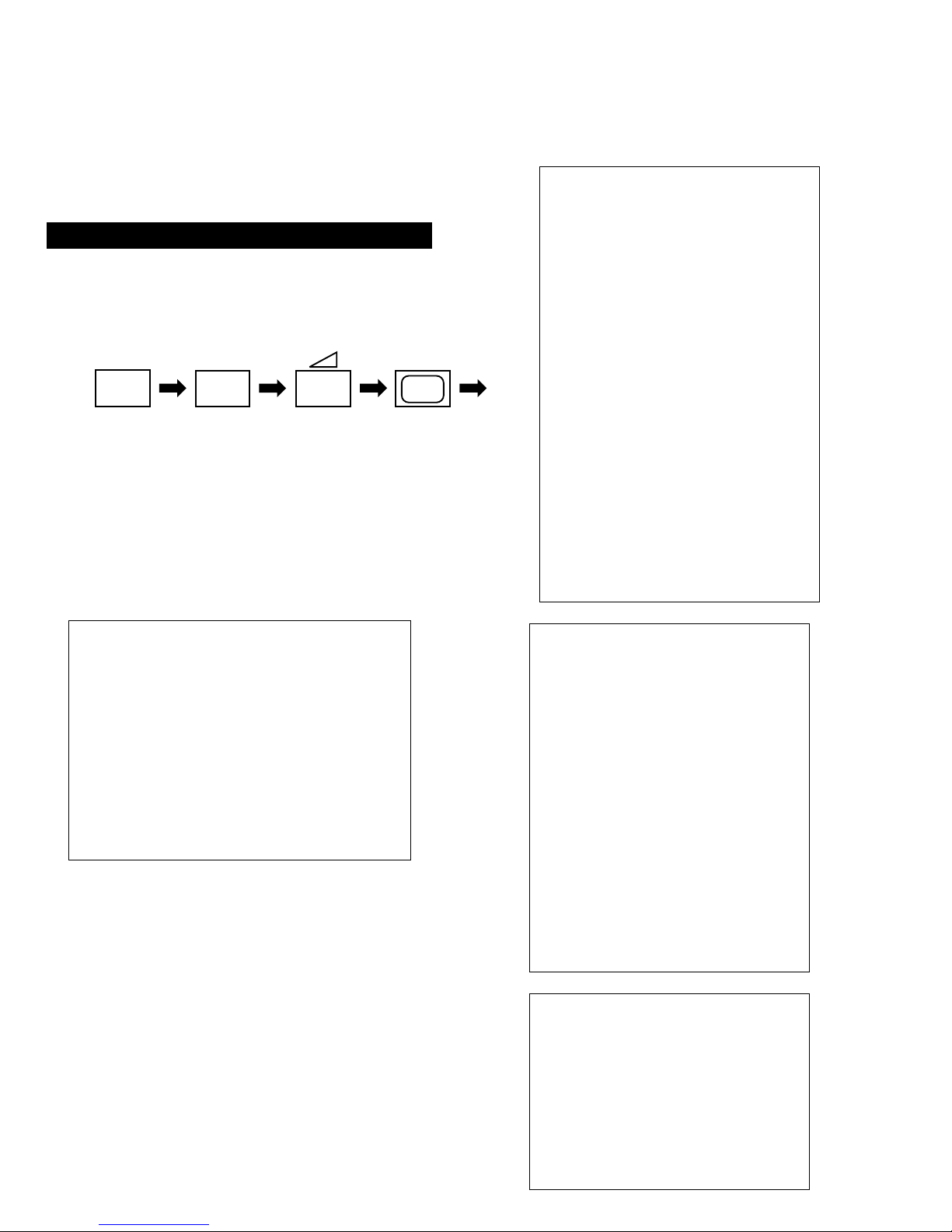
5
+
+
(ON SCREEN
DISPLAY)
(DIGIT 5) (VOLUME +) (TV)
4-1.ELECTRICAL ADJUSTMENTS
Service adjustments to this model can be performed
using the supplied Remote Commander R M- 931.
1. Turn on the main power switch and enter into the stand-by
mode.
2. Press the following sequence of buttons on the Remote
Commander.
• ‘TT--’ will appear in the upper right corner of the
screen.
Other status information will also be displayed.
3. Press ‘MENU’ on the remote commander to obtain the
following menu on the screen.
4. Move to the corresponding adjustment using t he Up/Down
Arrow button on the remote commander.
5. Press the Right Arrow button to enter the selected adjustment.
6. Turn off the power to quit the service mode when adjustments
have been completed.
HOW TO ENTER INTO SERVICE MODE
TEST MENU
> Picture Adjustment
Geometry
Wide
IC status
MSP
Dynamic Convergence
Current TV status
PICTURE ADJUSTMENT
AFC mode 1
REF position 1
SCP BGR 1
SCP BGF 1
Trap fo 10
Sub contrast Adj
Sub colour Adj
Sub brightness Adj
Green drive Adj
Blue drive Adj
Green cutoff Adj
Blue cutoff Adj
Gamma 0
Pre / overshoot 3
Y delay 2
D Pic ON
D Colour OFF
DC Transfe r OFF
GEOMETRY ADJUSTMENT - 4:3
V size Adj
V position A dj
S Correction Adj
V Linearity Adj
H size Adj
H position Adj
Pin Amp Adj
Pin Phase A dj
AFC Bow Adj
AFC Angle Adj
EHT V 1
EHT H 0
Lo Corn Pin Adj
Up Corn Pin Adj
WIDE ADJUSTMENT - 4:3
V Aspect 0
V Scroll 31
Upper V Lin 0
Lower V Lin 0
Left Blanking 7
Right Blanking 7
25
Same Level
B-Out Wavef orm
1. Input a Phillip s pat ter n.
2. Set the picture control to minimum.
3. Enter into the ‘Picture Adjustment’ service menu.
4. Adjust the ‘Sub-Brightness’ data so that there is barely a
difference between the 0 IRE and 10 IRE signal levels.
1. Input a video that contains a small 100% area on a black
background.
2. Set the picture control to maximum.
3. Connect an oscilloscope to Pin 3 of CN301 [A Board].
4. Enter into the ‘Picture Adjustment’ service menu.
5. Adjust the ‘Sub-contrast’ data to obtain a black to white
amplitude of 2.20V.
1. Receive a PAL colour bar video signal.
2. Connect an oscilloscope to Pin 3 of CN301 [A Board].
3. Enter into the ‘Picture Adjustment’ service menu.
4. Adjust the ‘Sub-colour’ data so that
the Cyan,
Magenta
and Blue
colour bars
are
of
equa
l height as indicated below.
MSP
NICAM Prescale I 127
NICAM Prescale L 97
NICAM Prescale BG 97
NICAM Prescale DK 97
AGC ON/OFF ON
Constant gain CDB 0
FM prescale FMP 36
Zwei mono-st WHI 36
Zwei st-mono WLO 18
Zwei mono-bi WMH 36
Zwei bi-mono WLO 18
Time Zwei WML 41
Fawct limit 10
Fawct soll init FAW 12
Faw ER Tol 2
Nicam Err Max CCT 10
Nicam Err Min 0
Time Nicam 26
Audio clock ACO HIZ
Scart prescale 25
Scart volume 64
IC STATUS (CXA2076 / CXA2040)
CXA2076
H lock 1
IKR 1
VNG 0
X-RA Y 0
Colour system 7
CV1 sync 0
CXA2040
Sync sep 1
S1 mode pin 01
S2 mode pin 01
TUNER
Tuner status 01100010
TV STATUS BE3E
Text system C TEXT 2
Dolby Enabled NO
DSP Present NO
Text language set WEST
Menu language set EAST
Destination B
Ageing Disabled
Auto Shut Off Enabled
Size 28
Colour trap sw ALL
Velocity mod ON
AFT STATUS WINDOW
Digital RF NO
Micro/Jungle S DA30C263/CXA2076
Dynamic Convergence
Range Adj 0 - 42
H stat Adj Off - 63
H amp l Adj Off - 63
H amp r Adj Off - 63
Up Y Adj Off - 63
Low Y Adj Off - 63
Y up l Adj Off - 63
Y up r Adj Off - 63
Y low l Adj Off - 63
Y low r Adj Off - 63
Mbow up l Adj Off - 63
Mbow up r Adj Off - 63
Mbow low l Adj Off - 63
Mbow low r Adj Off - 63
V Stat Adj Off - 63
SUB BRIGHTNESS ADJUSTMENT
SUB CONTRAST ADJUSTMENT
SUB COLOUR ADJUSTMENT
26
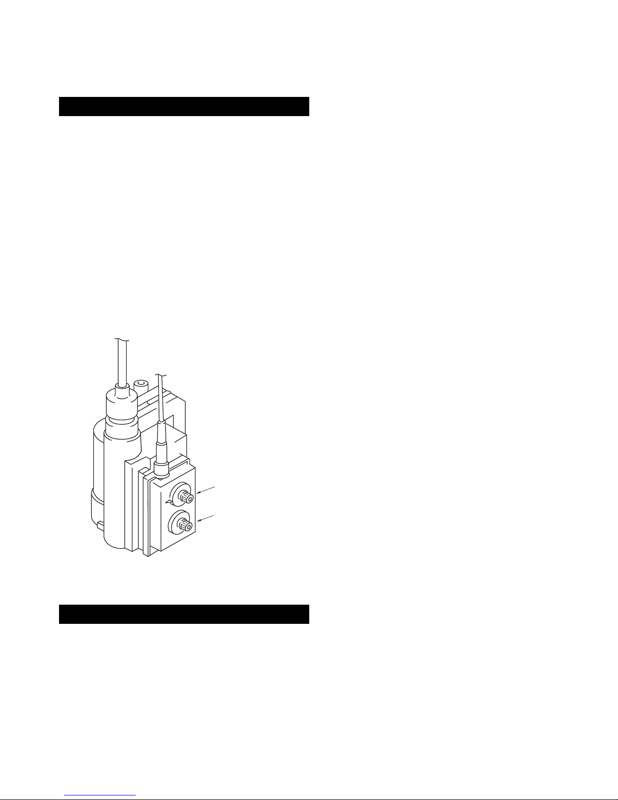
A
TUNER / IF
RV01
RV02 LV01
TP1
V SIZE
V LIN
S CORRECTION
V CENTRE
H SHIFT
H SIZE
PIN AMP
TILT
CORNER PIN
V ANGLE
1. Input an off air signal of between 60-100dBuV / 75 ohm
terminated, via the tuner socket.
2. Enter into th e ‘IF Adjustme nt’ service mode [i.e ‘ TT59’] t o f ix
the I.F frequency to 39.9MHz.
3. Enter into the service mode and select ‘Current TV status’.
4. Adjust the I.F coil [LV01] until the ‘AFT Status’ indicates a
‘Window’ condition.
1. Input an off air signal of between 60-100dBuV / 75 ohm
terminated, via the tuner socket.
2. Enter in to the ‘IF Adjustmen t’ service m ode [i.e ‘ TT59’] t o f ix
the I.F frequency to 34.2MHz.
3. Enter into the service mode and select ‘Current TV status’.
4. Adjust the RV02 control until the ‘AFT Status’ indicates a
‘Window’ condition.
1. Receive a signal of 63dBuV / 75 ohm terminated, via the tuner
socket.
2. Measure the voltage at test point 1 [A Board].
3. Adjust RV01 control to obta in a voltage of 3.0V +/- 0.3V.
1. Enter into the ‘Geometry Adjustment’ service menu.
2. Select and adjust each item in order to obtain the optimum
image.
SYSTEM B/G, D/K, I & L I.F ADJUSTMENT
SYSTEM L BAND 1 I.F ADJUSTMENT
STUNER AGC ADJUSTMENT
DEFLECTION SYSTE M ADJUSTMENT
GEOMETRY ADJUSTMENT
V size Adj
V position A dj
S Correction Adj
V Linearity Adj
H size Adj
H position Adj
Pin Amp Adj
Pin Phase A dj
AFC Bow Adj
AFC Angle Adj
EHT V 1
EHT H 0
Lo Corn Pin Adj
Up Corn Pin Adj
 Loading...