

Sony TRINITRON KV-21FX20A, TRINITRON KV-21FX20B, TRINITRON KV-21FX20R, TRINITRON KV-21FX20D, TRINITRON KV-21FX20E Service Manual
...
SERVICE MANUAL FE-1A CHASSIS
MODEL COMMANDER DEST CHASSIS NO. MODEL COMMANDER DEST CHASSIS NO.
KV-21FX20A
KV-21FX20B
KV-21FX20D
RM-887 Italian SCC-Q32D-A
RM-887 French SCC-Q33D-A
RM-887 AEP SCC-Q31D-A
KV-21FX20E
KV-21FX20K
KV-21FX20R
RM-887 Spanish SCC-Q34D-A
RM-887 OIRT SCC-Q36E-A
RM-887 OIRT SCC-Q36F-A
MICROFILM
TRINITRON
1
®
COLOR TV
®
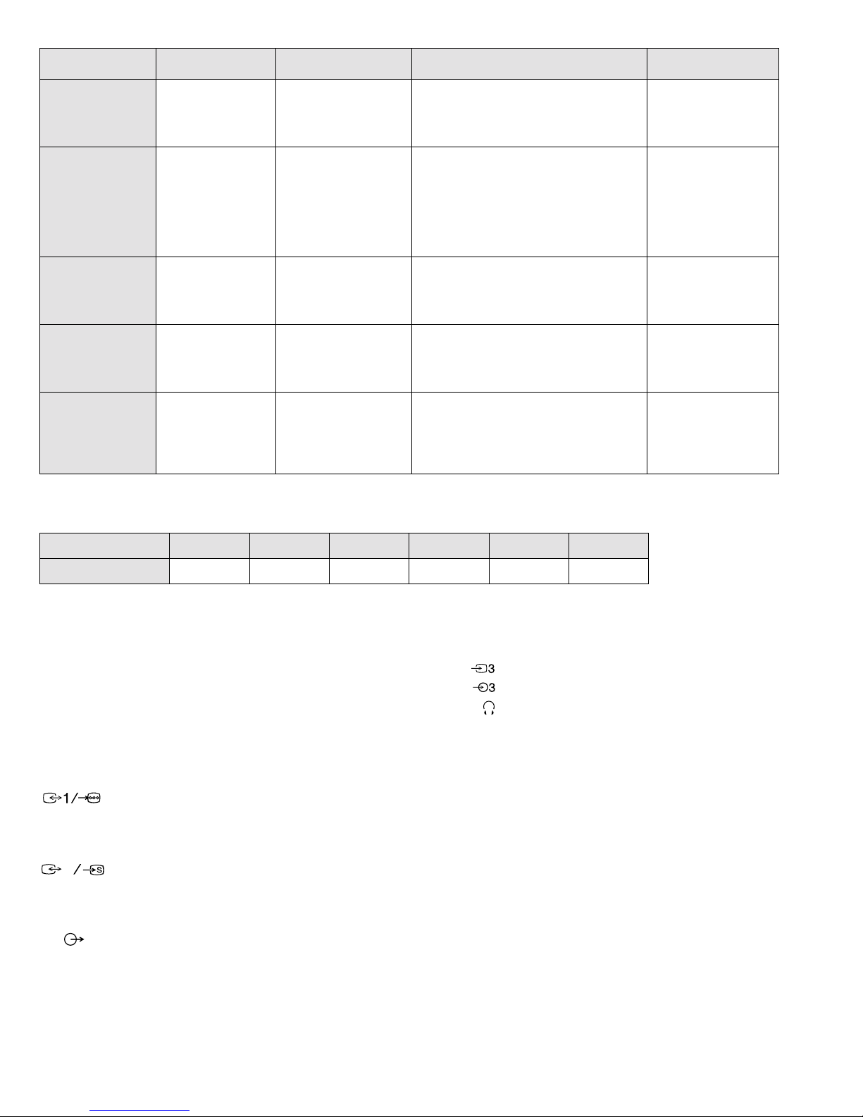
ITEM MODEL Television System Stereo System Channel Coverage Color System
Italian B/G/H GERMAN Stereo
French B/G/H, D/K, L, I GERMAN/NICAM
AEP B/G/H GERMAN Stereo
Spanish B/G/H GERMAN/NICAM
OIRT B/G/H, D/K
Stereo
Stereo
KV-21FX20K
GERMAN/NICAM
Stereo
KV-21FX20R
GERMAN Stereo
IT ALIA VHF : A-H2 (C) UHF : 21-69 P AL
B/G/H VHF : E2-E12 UHF : E21-E69
CABLE TV (1) : S1-S41
CABLE TV (2) : S01-S05, M1-M10, U1-U10
L VHF : F02-F10 UHF : F21-F60
CABLE : B-Q B/G/H VHF : E2-E12
UHF : E21-E69
CABLE TV (1) : S1-S41
CABLE TV (2) : S01-S05, M1-M10, U1-U10
ITALIA VHF : A-H2 (C) UHF : 21-69
I UHF : B21-B69
P AL B/G/H VHF : E2-E12 UHF : E21-E69
CABLE TV (1) : S1-S41
CABLE TV (2) : S01-S05, M1-M10, U1-U10
ITALIA VHF : A-H2 (C) UHF : 21-69
P AL B/G VHF : E2-E12 UHF : E21-E69
CABLE TV (1) : S1-S41
CABLE TV (2) : S01-S05, M1-M10, U1-U10
ITALIA VHF : A-H2 (C) UHF : 21-69
B/G/H VHF : E2-E12 UHF : E21-E69
CABLE TV (1) : S1-S41
D/K VHF : R01-R12 UHF : R21-R69
P AL, SECAM
NTSC4.43, NTSC3.58
(VIDEO IN)
P AL, SECAM
NTSC4.43, NTSC3.58
(VIDEO IN)
P AL, SECAM
NTSC4.43, NTSC3.58
(VIDEO IN)
P AL, SECAM
NTSC4.43, NTSC3.58
(VIDEO IN)
P AL, SECAM
NTSC4.43, NTSC3.58
(VIDEO IN)
MODEL 21FX20A 21FX20B 21FX20D 21FX20E 21FX20K 21FX20R
Power Consumption 80W 80W 80W 80W 80W 80W
[PICTURE TUBE] FD Trinitron
Approx. 55cm (21 inches)
(Approx. 51cm picture measured
diagonally)
110 degree deflection
Input/Output Terminals
[REAR]
21-pin Euro connector (CENELEC standard).
- Inputs for Audio and Video signals.
- Inputs for RGB.
- Outputs of TV Video and Audio signals.
2
21-pin Eur o connector.
[FRONT]
Video input - phono jack
Audio inputs - phono jacks
Headphone jacks : stereo minijack
Sound output 2 x 7W (RMS)
Power requirements 220 - 240V
Dimensions Approx 545x446x485mm (w/h/d)
Weight Approx 26.5kg
Supplied accessories RM-887 Remote Commander (1)
IEC designated R6 battery (2)
Other features NICAM*, FASTEXT, TOPTEXT
(KV-21FX20B/21FX20E/21FX20K only)
*
- inputs for Audio and Video signals.
- inputs for S Video.
- outputs for Audio and Video signals (selectable).
Phono Jack
- Outputs for Audio Signals
2
[RM-887]
Remote control system Infrared control
Power requirements 3V dc
2 batteries IEC designation
R6 (size AA)
Dimensions Approx 44x209x23mm (w/h/d)
Weight Approx 89g (Not including battery)
Design and specifications are subject to change without notice.
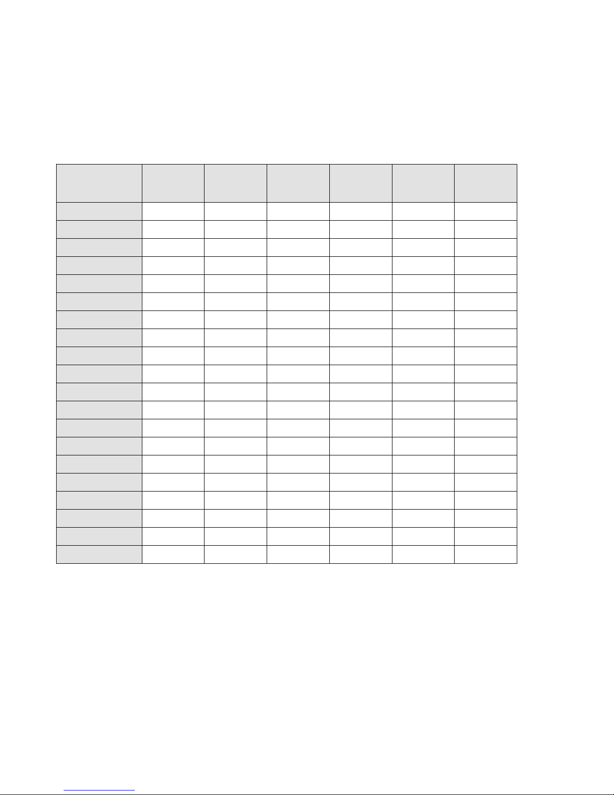
Model Name
Item
Pal Comb OFF OFF OFF OFF OFF OFF
PIP OFF OFF OFF OFF OFF OFF
RGB Priority OFF ON ON ON OFF OFF
Woofer Box OFF OFF OFF OFF OFF OFF
Scart 1 ON ON ON ON ON ON
Scart 2 ON ON ON ON ON ON
Front in (3) OFF OFF OFF OFF OFF OFF
Scart 4 OFF OFF OFF OFF OFF OFF
KV-21FX20A KV-21FX20B KV-21FX20D KV-21FX20E KV-21FX20K KV-21FX20R
Proj ect o r OFF OFF OFF OFF OFF OFF
AKB in 16:9 mode ON ON ON ON ON ON
Norm B/G ON ON ON ON ON ON
Norm I OFF ON OFF OFF OFF OFF
Norm D/K OFF ON OFF OFF ON ON
Norm AUS OFF OFF OFF OFF OFF OFF
Norm L OFF ON OFF OFF OFF OFF
Norm SAT OFF OFF OFF OFF OFF OFF
Norm M OFF OFF OFF OFF OFF OFF
Teletext ON ON ON ON ON ON
Nicam Stereo OFF ON OFF ON ON OFF
Language Preset Italian French German Spanish OIRT OIRT
3
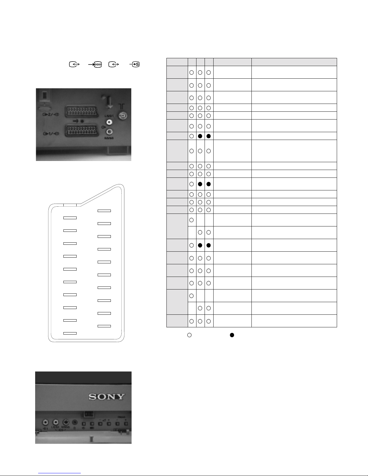
21 pin connector ( 1/ , 2 / )
21
20
19
18
17
16
15
14
13
12
11
10
9
8
7
6
5
4
3
2
1
Pin No 1 2 4 Signal Signal level
1 Audio output B
2
3
4 Ground (audio)
5 Ground (blue)
6 Audio input A
7 Blue input 0.7 +/- 3dB, 75 ohms positive
8 Function select
9 Ground (green)
10 Open
11 Green Green signal : 0.7 +/- 3dB, 75 ohms,
12 Open
13 Ground (red)
14 Ground (blanking)
15
_ (S signal Chroma
16 Blanking input
17 Ground (video
18 Ground (video
19 Video output 1V +/- 3dB, 75ohms, positive sync 0.3V
20
_ Video input
21 Common ground
Connected Not Connected (open) * at 20Hz - 20kHz
(right)
Audio output B
(right)
Audio output A
(left)
(left)
(AV control)
_ _ Red input 0.7 +/- 3dB, 75 ohms, positive
input)
(Ys signal)
output)
input)
_ _ Video input 1V +/- 3dB, 75ohms, positive sync 0.3V
Y (S signal)
(plug, shield)
Standard level : 0.5V rms
Output impedence : Less than 1kohm*
Standard level : 0.5V rms
Output impedence : More than 10kohm*
Standard level : 0.5V rms
Output impedence : Less than 1kohm*
Standard level : 0.5V rms
Output impedence : More than 10kohm*
High state (9.5-12V) : Part mode
Low state (0-2V) : TV mode
Input impedence : More than 10K ohms
Input capacitance : Less than 2nF
positive
0.3 +/- 3dB, 75 ohms, positive
High state (1-3V) Low state (0-0.4V)
Input impedence : 75 ohms
(-3+10dB)
(-3+10dB)
1V +/- 3dB, 75ohms, positive sync 0.3V
(-3+10dB)
4

TABLE OF CONTENTS
Section Title Page Section Title Page
FE-1A Self Diagnostic Software .....................6
4. CIRCUIT ADJUSTMENTS
1. GENERAL
Automatically tuning the TV
Using the Remote Control .....................7
Manually Tuning the TV .....................8
Adjusting the Picture .....................9
Adjusting the Sound .....................9
Viewing Teletext .....................10
Using Optional Equipment .....................10
Troubleshooting .....................11
Specifications .....................11
2. DISASSEMBLY
2-1. Rear Cover Removal .....................12
2-2. Chassis Assy Removal .....................12
2-3. Service Position .....................12
2-4. S1 Board Removal .....................13
2-5. Picture Tube Removal .....................14
2-6. Removal and Replacement of
the Main - Bracket bottom plates .....................15
3. SET-UP ADJUSTMENTS
3-1. Beam Landing .....................16
3 - 2 . C o n v e r g e n c e . . . . . . . . . . . . . . . . . . . . . 1 7
3-3. Focus .....................19
3-4. White Balance .....................19
4-1. Electrical Adjustments .....................20
4-2. Test Mode 2 .....................23
5. DIAGRAMS
5-1. Block Diagram .....................25
5-2. Circuit Board Location .....................30
5-3. Schematic Diagrams and
Printed Wiring Boards .....................30
* A Board .....................35
* S1 Board .....................40
* CVM Board .....................43
5-4. Semiconductors .....................45
5-5. IC Blocks .....................47
6. EXPLODED VIEWS
6-1. Chassis .....................48
6-2. Picture Tube .....................49
7. ELECTRICAL PARTS LIST
.....................50
CAUTION
SHORT CIRCUIT THE ANODE OF THE PICTURE TUBE AND THE
ANODE CAP TO THE METAL CHASSIS, CRT SHIELD, OR THE
CARBON PAINTED ON THE CRT, AFTER REMOVAL OF THE
ANODE CAP
WARNING !!
AN ISOLATING TRANSFORMER SHOULD BE USED DURING ANY
SERVICE WORK TO AVOID POSSIBLE SHOCK HAZARD DUE TO
LIVE CHASSIS. THE CHASSIS OF THIS RECEIVER IS DIRECTLY
CONNECTED TO THE POWER LINE.
SAFETY-RELATED COMPONENT WARNING !!
COMPONENTS IDENTIFIED BY SHADING AND MARKED ON
THE SCHEMATIC DIAGRAMS, EXPLODED VIEWS AND IN THE
PAR T S LIST ARE CRITICAL FOR SAFE OPERATION. REPLACE
THESE COMPONENTS WITH SONY PARTS WHOSE PART NUMBERS
APPEAR AS SHOWN IN THIS MANUAL OR IN SUPPLEMENTS
PUBLISHED BY SONY.
ATTENTION
APRES AVOIR DECONNECTE LE CAP DE’LANODE,
COURT-CIRCUITER L’ANODE DU TUBE CATHODIQUE ET
CELUI DE L’ANODE DU CAP AU CHASSIS METALLIQUE
DE L’APPAREIL, OU AU COUCHE DE CARBONE PEINTE
SUR LE TUBE CATHODIQUE OU AU BLINDAGE DU TUBE
CATHODIQUE.
ATTENTION !!
AFIN D’EVITER TOUT RISQUE D’ELECTROCUTION PROVENANT
D’UN CHÁSSIS SOUS TENTION, UN TRANSFORMATEUR
D’ISOLEMENT DOIT ETRE UTILISÈ LORS DE TOUT DÈPANNAGE.
LE CHÁSSIS DE CE RÈCEPTEUR EST DIRECTMENT RACCORDÈ
Á L’ALIMENTATION SECTEUR.
ATTENTION AUX COMPOSANTS RELATIFS Á LA
SÈCURITÈ !!
LES COMPOSANTS IDENTIFIÈS PAR UNE TRAME ET PAR UNE
MARQUE SUR LES SCHÈMAS DE PRINCIPE, LES VUES
EXPLOSÈES ET LES LISTES DE PIECES SONT D’UNE IMPORTANCE
CRITIQUE POUR LA SÈCURITÈ DU FONCTIONNEMENT, NE LES
REMPLACER QUE PAR DES COMPSANTS SONY DONT LE NUMÈRO
DE PIÈCE EST INDIQUÈ DANS LE PRÈSENT MANUEL OU DANS
DES SUPPLÈMENTS PUBLIÈS PAR SONY.
5
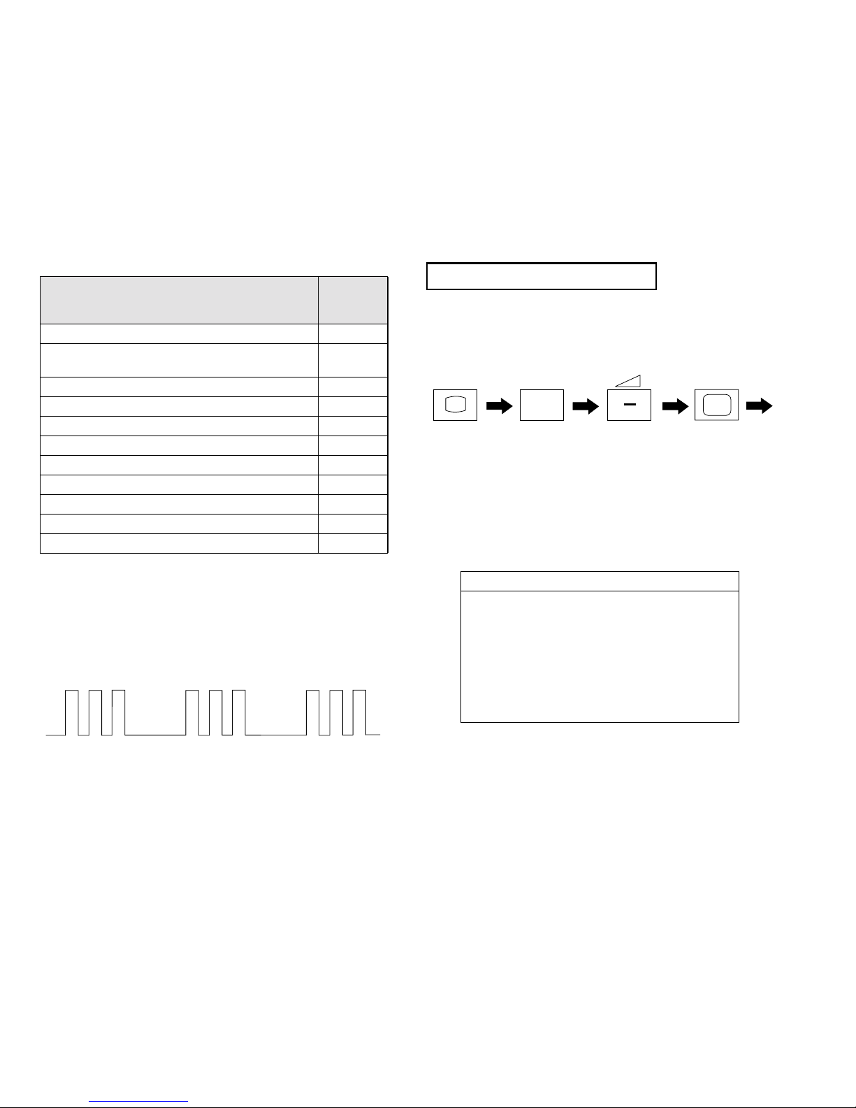
FE-1A SELF DIAGNOSTIC SOFTWARE
The identification of errors within the FE-1A chassis is triggered in one of two ways :- 1: Busy or 2: Device failure to respo nd to IIC. In the event
of one of these situations arising the software will first try to release the bus if busy (Failure to do so will report with continuous flashing LED) and
then communicate with each device in turn to establish if a device is faulty. If a device is found to be faulty the relevant device number will be displayed through the LED (Series of flashes which must be counted) See Table 1., non fatal errors are reported using this method.
Each time the software detects an error it is stored within the NVM. See Table 2.
Table 1
ERROR
No error 00
Not allowed (may be confused with Sircs response
flash!)
Protection circuit trip < ANY TIME > 02
Reserved 03
No vertical sync 04
AKB 05
IIC bus clock and/or data lines low at Power ON 06
NVM no IIC bus acknowledge at Power ON 07
Jungle controller no IIC acknowledge at Power ON 08
Tuner no acknowledge at Power ON 09
Sound processor no acknowledge at Power ON 10
Flash Timing Example : e.g. error number 3
StBy LED
ON ON ON
OFF OFF
LED
ERROR
COUNT
01
How to enter into Table 2
1. Turn on the main power switch of the TV set and enter into the
‘Standby Mode’.
2. Press the following sequence of buttons on the Remote
Commander.
+
i
(ON SCREEN
DISPLAY)
3. The following table will be displayed indicating the error
count.
Table 2
5
(DIGIT 5) (VOLUME -)
Error Times
2 -
3 4 5 6 7 8 9 10 -
(TV)
Note: To clear the error count data press ‘80’ on the Remote
commander.
6
7
10
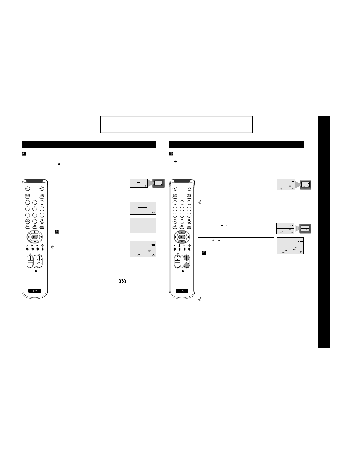
First Time Operation - Basic Presetting
Automatically Tuning the TV using the Remote Control
You need to tune the TV to receive channels (TV Broadcast). By following the instructions below, this TV automatically
searches and stores all available channels for you.
After having selected the language, a new menu appears automatically on the TV screen asking you to automatically tune
the TV. However, if you need to change or repeat the tuning afterwards (e.g. when you move house), select the menu
AUTO PROGRAMME in the
(SET UP) menu and proceed in the same way as described below in step 1 or, please refer
to the section "Automatically Tuning the TV using the TV buttons" of this instruction manual.
1
Press the OK button on the remote control to select YES.
A new menu appears automatically on the screen asking you to
check that the antenna is connected.
2
Confirm that the antenna is connected and then press the OK
button.
The automatic tuning starts and the message "Searching..." flashes
on the screen.
This procedure could take some minutes.
When the automatic tuning is finished, the Programme Sorting menu
appears on the TV screen.
Notes: • To stop the automatic tuning, press the MENU button.
• If you stop the automatic tuning by pressing the MENU
button, the Programme Sorting menu does not appear
automatically on the TV screen.
First Time Operation - Basic Presetting
Do you want to start
automatic tuning?
YES
NO
Please confirm that
antenna is connected
CONFIRM
AUTO PROGRAMME
PROGRAMME:
SYSTEM:
CHANNEL:
Searching...
01
B/G
C 21
01
Select Channel:
Select new position:
Confirm:
Exit:
PROGRAMME SORTING
PROGR
PROGRAMME:
CONFIRM
MENU
03
S
RM
887
PROGR
MENU
1
4
7
2
5
8
0
3
6
9
K
Do you want to start
automatic tuning?
YES
NO
11
a) If you do not wish to change the channel order:
1
Press the MENU button to exit and return to the normal TV screen.
Your TV is now ready for use.
b) If you wish to change the channel order:
1
Press the PROGR or button until the channel (TV Broadcast) you
wish to rearrange appears on the screen.
2
Press the or button to select the new programme number
position for your selected channel (TV Broadcast), then press the
OK button.
The word CONFIRM is highlighted for a few seconds to
confirm that the new programme position is stored.
3
Repeat steps 1 and 2 if you wish to change the order of the other
channels on your TV.
4
Press the MENU button to exit and return to the normal TV screen.
Your TV is now ready for use.
First Time Operation - Basic Presetting
First Time Operation - Basic Presetting
Changing the Programme Order of the TV channels
After all available channels (TV Broadcast) are captioned and stored, a new menu appears automatically on the screen to
change the order in which the channels appear on the screen.
However, if you wish to rearrange the order of the channels afterwards, select the menu PROGRAMME SORTING in the
(SET UP) menu and proceed in the same way as described in the b) section of this chapter.
01
Select Channel:
Select new position:
Confirm:
Exit:
PROGRAMME SORTING
PROGR
PROGRAMME:
CONFIRM
MENU
03
02
Select Channel:
Select new position:
Confirm:
Exit:
PROGRAMME SORTING
PROGR
PROGRAMME:
CONFIRM
MENU
04
S
RM
887
PROGR
MENU
1
4
7
2
5
8
0
3
6
9
K
01
Select Channel:
Select new position:
Confirm:
Exit:
PROGRAMME SORTING
PROGR
PROGRAMME:
CONFIRM
MENU
03
01
Select Channel:
Select new position:
Confirm:
Exit:
PROGRAMME SORTING
PROGR
PROGRAMME:
CONFIRM
MENU
03
01
Select Channel:
Select new position:
Confirm:
Exit:
PROGRAMME SORTING
PROGR
PROGRAMME:
CONFIRM
MENU
03
The operating instructions mentioned here are partial abstracts from the ‘Operating
Instruction Manual’. The page numbers of the ‘Operating Instruction Manual’ remain
as in the manual.
SECTION 1 GENERAL
8
12
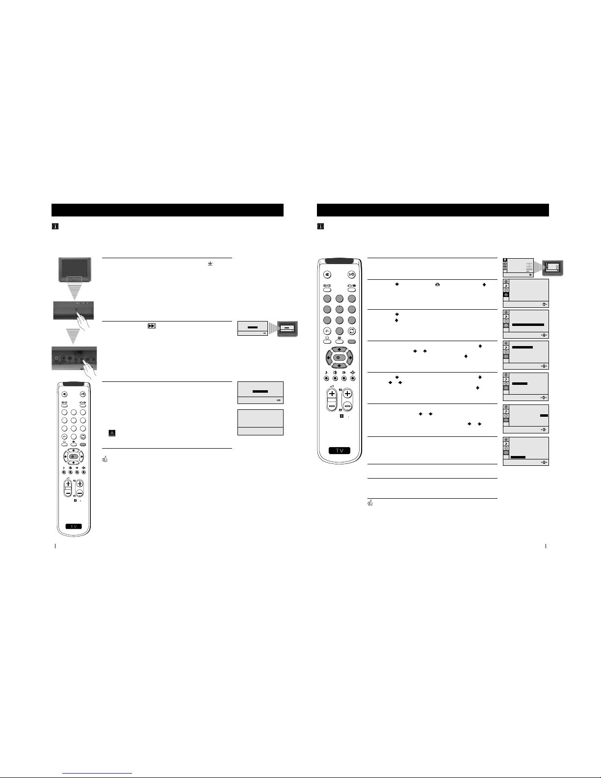
Advanced Operation - Advanced Presetting
Automatically Tuning the TV using the TV buttons
Besides the explanation in the section “Automatically Tuning the TV using the Remote Control“, by following the
instructions below, this TV also searches and stores automatically all available channels using just one button of the TV set.
1
Press the flap on the front of the TV by pressing on the mark to
reveal the front control panel.
2
Press and hold in the button on the TV set for some seconds,
until a menu appears automatically on the screen asking you to
check that antenna is connected.
3
Confirm that the antenna is connected and then press the OK
button.
The automatic tuning starts and the message "Searching..." flashes
on the screen.
This procedure could take some minutes.
When the automatic tuning procedure is complete, the menu disappears
from the TV screen and your TV is now ready for use.
Note: To stop the automatic tuning, press the MENU button on the
remote control.
Advanced Operation - Advanced Presetting
S
RM
887
PROGR
MENU
1
4
7
2
5
8
0
3
6
9
K
AUTO PROGRAMME
PROGRAMME:
SYSTEM:
CHANNEL:
Searching...
01
B/G
C 21
Please confirm that
antenna is connected
CONFIRM
Please confirm that
antenna is connected
CONFIRM
Please confirm that
antenna is connected
CONFIRM
13
Advanced Operation - Advanced Presetting
Advanced Operation - Advanced Presetting
Manually Tuning the TV
Use this function to preset channels or a video input source one by one to the programme order of your choice.
1
Press the MENU button on the remote control to display the
menu on the TV screen.
2
Press the button to select the symbol, then press the
button to enter to the SET UP menu.
3
Press the button to select MANUAL PROGRAMME, then
press the
button.
4
With the cursor highlighting PROGRAMME, press the button
and then, press the
or button to select on which programme
number you want to preset a channel. Press the
button.
5
Press the button to select CHANNEL, then press the button.
Press
or button to select the channel tuning, "C" for
terrestrial channels or "S" for cable channels. Press the
button.
6
Press the number buttons to enter the channel number of the TV
Broadcast or press the
or button to search for the next
available channel.
If you do not wish to store this channel, press the
or button
to continue searching for the desired channel.
7
If this is the desired channel you wish to store, press the OK
button and then, with the cursor highlighting CONFIRM, press
the OK button again.
8
Repeat steps 4 to 7 if you wish to store more channels.
9
Press the MENU button to exit and return to the normal TV
screen.
Your TV is now ready for use.
PICTURE CONTROL
CONTRAST
BRIGHTNESS
COLOUR
SHARPNESS
HUE
RESET
MODE: PERSONAL
0
SET UP
PICTURE ROTATION:
LANGUAGE: ENGLISH
AUTO PROGRAMME
PROGRAMME SORTING
MANUAL PROGRAMME
0
SET UP
PICTURE ROTATION:
LANGUAGE: ENGLISH
AUTO PROGRAMME
PROGRAMME SORTING
MANUAL PROGRAMME
01
B/G
C 21
ON
NO
OFF
SET UP:
MANUAL PROGRAMME
CONFIRM
PROGRAMME:
SYSTEM:
CHANNEL:
AFT:
SKIP:
DECODER:
SET UP:
MANUAL PROGRAMME
CONFIRM
PROGRAMME:
SYSTEM:
CHANNEL:
AFT:
SKIP:
DECODER:
01
B/G
C 21
ON
NO
OFF
01
B/G
C 21
ON
NO
OFF
SET UP:
MANUAL PROGRAMME
CONFIRM
PROGRAMME:
SYSTEM:
CHANNEL:
AFT:
SKIP:
DECODER:
S
RM
887
PROGR
MENU
1
4
7
2
5
8
0
3
6
9
K
PICTURE CONTROL
CONTRAST
BRIGHTNESS
COLOUR
SHARPNESS
HUE
RESET
MODE: PERSONAL
01
B/G
C 21
ON
NO
OFF
SET UP:
MANUAL PROGRAMME
CONFIRM
PROGRAMME:
SYSTEM:
CHANNEL:
AFT:
SKIP:
DECODER:
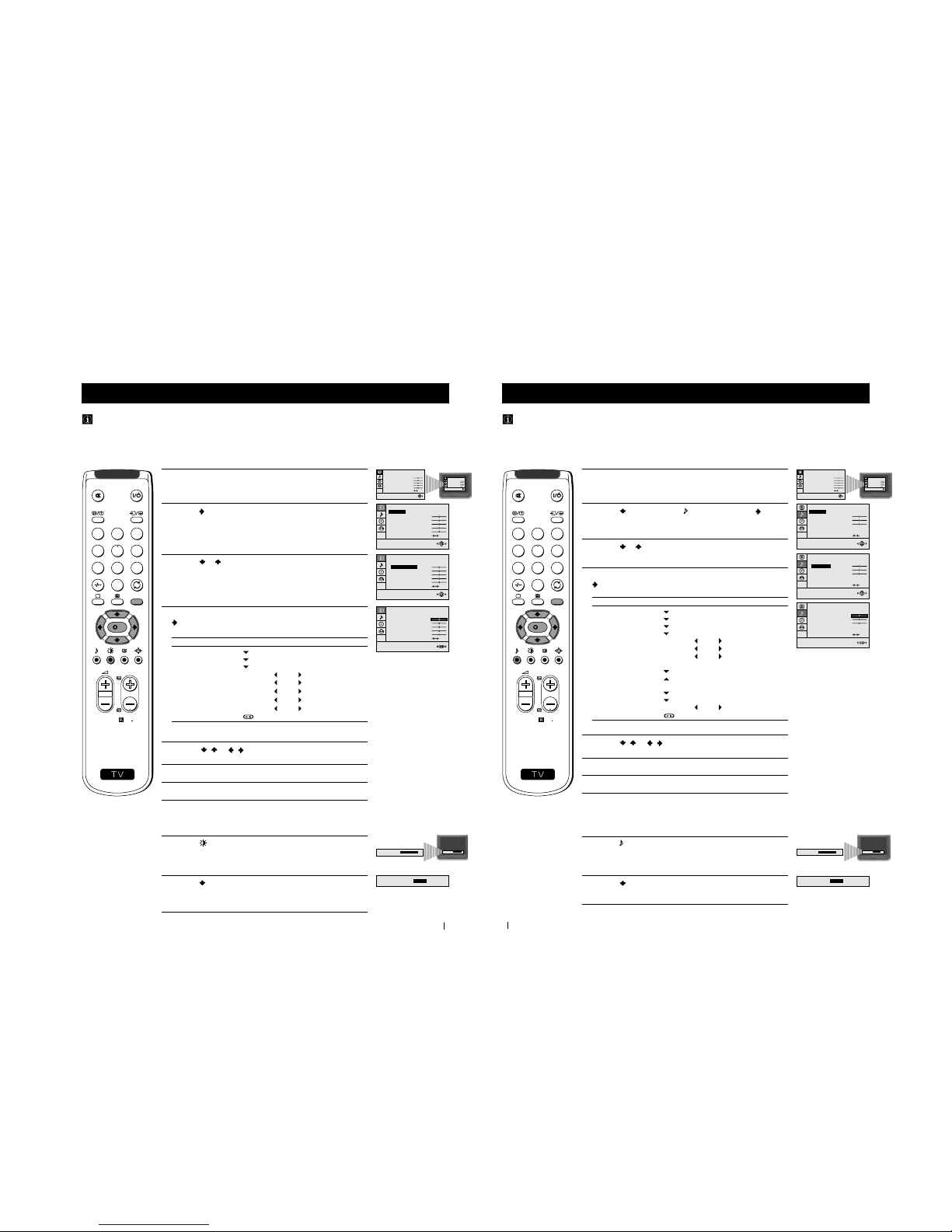
9
17
1
Press the MENU button on the remote control to display the menu
on the TV screen.
2
Press the button to enter to the PICTURE CONTROL menu.
3
Press the or button to select the item you wish to change.
4
With the cursor highlighting the item you wish to change, press the
button.
(Refer to the table below for the effect of each control).
5
Press the / or / button to alter the selected item, then
press the OK button to store the new adjustment.
6
Repeat steps 3 to 5 to alter the other items.
7
Press the MENU button to exit and return to the normal TV screen.
PICTURE CONTROL OPERATION / EFFECT
MODE
PERSONAL (for individual settings)
LIVE (for live broadcast programmes)
MOVIE (for films)
CONTRAST Less
More
BRIGHTNESS
*
Darker Brighter
COLOUR
*
Less More
SHARPNESS
*
Softer Sharper
HUE
**
Greenish Reddish
RESET Resets picture to the factory preset levels.
*
Can be only altered if PERSONAL MODE is selected.
**
Only avalaible for NTSC colour signal (e.g: US video tapes).
Advanced Operation - Advanced TV Operation
Adjusting the Picture
Although the picture is adjusted at the factory, you can modify it to suit your own taste.
Changing Picture Mode Quickly
1
Press the button on the remote control to directly access the
PICTURE MODE.
2
Press the button to select your desired picture mode
(PERSONAL, LIVE or MOVIE).
Advanced Operation - Advanced TV Operation
PICTURE CONTROL
CONTRAST
BRIGHTNESS
COLOUR
SHARPNESS
HUE
RESET
MODE: PERSONAL
PICTURE CONTROL
MODE: PERSONAL
CONTRAST
BRIGHTNESS
COLOUR
SHARPNESS
HUE
RESET
PICTURE CONTROL
MODE: PERSONAL
CONTRAST
BRIGHTNESS
COLOUR
SHARPNESS
HUE
RESET
PICTURE MODE:
PICTURE MODE:
LIVE
S
RM
887
PROGR
MENU
1
4
7
2
5
8
0
3
6
9
K
PICTURE CONTROL
CONTRAST
BRIGHTNESS
COLOUR
SHARPNESS
HUE
RESET
MODE: PERSONAL
PICTURE CONTROL
CONTRAST
BRIGHTNESS
COLOUR
SHARPNESS
HUE
RESET
MODE: PERSONAL
PICTURE MODE:
PERSONAL
PICTURE MODE:
PERSONAL
18
1
Press the MENU button on the remote control to display the menu
on the TV screen.
2
Press the button to select the symbol, then press the button
to enter to the SOUND CONTROL menu.
3
Press the or button to select the item you wish to change.
4
With the cursor highlighting the item you wish to change, press the
button.
(Refer to the table below for the effect of each control).
5
Press the / or / button to alter the selected item, then
press the OK button to store the new adjustment.
6
Repeat steps 3 to 5 to alter the other items.
7
Press the MENU button to exit and return to the normal TV screen.
SOUND CONTROL OPERATION / EFFECT
MODE
PERSONAL (for individual settings)
JAZZ
POP
ROCK
TREBLE
*
Less More
BASS
*
Less More
BALANCE Left
Right
DUAL SOUND • For a stereo broadcast:
MONO
STEREO
• For a bilingual broadcast:
A (for channel 1 or Mono sound)
B (for channel 2)
DSP
(Digital sound Processor)
ON OFF
RESET Resets sound to the factory preset levels.
*
Can be only altered if PERSONAL MODE is selected.
Advanced Operation - Advanced TV Operation
Adjusting the Sound
Although the sound is adjusted at the factory, you can modify it to suit your own taste.
Changing Sound Mode Quickly
1
Press the button on the remote control to access directly to the
SOUND MODE.
2
Press the button to select your desired sound mode
(PERSONAL, JAZZ, POP or ROCK).
Advanced Operation - Advanced TV Operation
STEREO
ON
SOUND CONTROL
TREBLE
BASS
BALANCE
DUAL SOUND:
DSP:
RESET
MODE: PERSONAL
STEREO
ON
SOUND CONTROL
MODE: PERSONAL
TREBLE
BASS
BALANCE
DUAL SOUND:
DSP:
RESET
STEREO
ON
SOUND CONTROL
MODE: PERSONAL
TREBLE
BASS
BALANCE
DUAL SOUND:
DSP:
RESET
SOUND MODE:
PERSONAL
SOUND MODE:
POP
S
RM
887
PROGR
MENU
1
4
7
2
5
8
0
3
6
9
K
PICTURE CONTROL
CONTRAST
BRIGHTNESS
COLOUR
SHARPNESS
HUE
RESET
MODE: PERSONAL
PICTURE CONTROL
CONTRAST
BRIGHTNESS
COLOUR
SHARPNESS
HUE
RESET
MODE: PERSONAL
SOUND MODE:
PERSONAL
10
21
Teletext
Teletext
Viewing Teletext
Using Fastext
Fastext lets you access pages with one button stroke.
When Fastext is broadcast, a colour coded menu appears at the
bottom of the teletext page. Press the colour button (red, green,
yellow or blue) on the remote control to access the corresponding
page.
Index
TELETEXT
Programme
News
Sport
Weather
25
153
101
98
Index
TELETEXT
TELETEXT
Programme
News
Sport
Weather
25
153
101
98
Index
TELETEXT
TELETEXT
Programme
News
Sport
Weather
25
153
101
98
Index
TELETEXT
TELETEXT
Programme
News
Sport
Weather
25
153
101
98
Selecting Teletext
1
Select the TV channel which carries the teletext service you wish to
view.
2
Press the button on the remote control to switch on the teletext.
3
Input three digits for the page number, using the numbered buttons
on the remote control. (if you have made a mistake, type in any
three digits and then, re-enter the correct page number).
4
Press the button to switch off teletext.
Using other Teletext functions
TO PRESS THE BUTTON
Access the next or preceding page
for next page or
for the preceding page
Superimpose teletext on to the TV
Press again to cancel teletext
mode.
Freeze a teletext page
Press again to cancel the
freeze.
Reveal concealed information
(e.g: answer to a quiz) Press again to cancel.
Teletext is an information service transmitted by most TV stations.
Make sure to use a TV channel with a strong signal, otherwise teletext errors may occur.
S
RM
887
PROGR
MENU
1
4
7
2
5
8
0
3
6
9
K
22
Front of TV
8mm/Hi8
camcorder
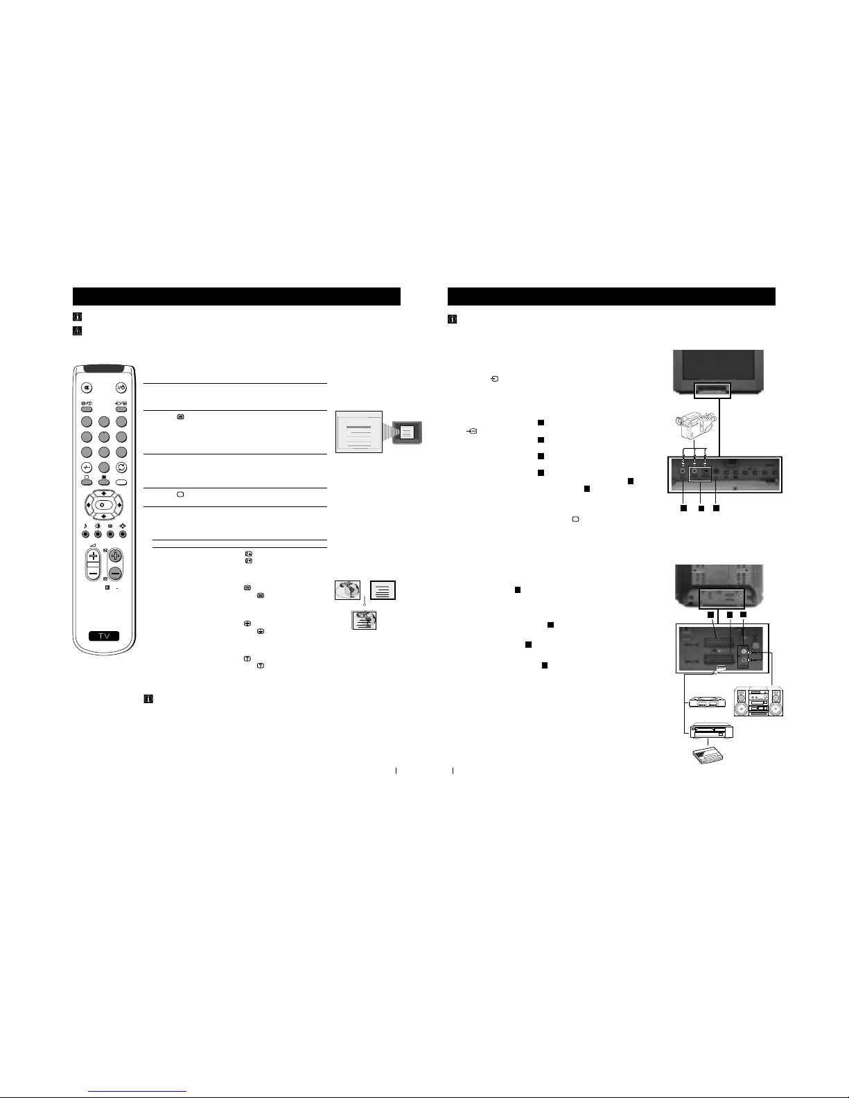
Optional Connections
You can connect optional audio or video equipment to your TV, such as a VCR, a camcorder or a video game as shown
below.
Using Optional Equipment
B
C
A
Select and View the Input Signal
1
Connect your equipment to the designated TV socket.
2
Press
the
button repeatedly on your remote control until the correct
input symbol appears on the TV screen.
Symbol Input signals
k
• Audio/video input signal through the Euro AV
connector
E
• RGB input signal through the Euro AV
connector
E
K
• Audio/video input signal through the Euro AV
connector
D
q
• S video input signal through the Euro AV
connector
D
K
• Video input signal through the phono socket
A
and
Audio input signal through
B
3
Switch on the connected equipment.
4
To return to normal TV picture, press the
button on the remote control.
Additional Information
Connecting a VCR
Plug in VCR to the socket
E
on the rear of the TV set.
We recommend you tune in the VCR signal to TV programme number ‘0’ using
the section “Manually Tuning the TV“ of this instruction manual.
Connecting Headphones
Plug in your headphones to the socket
C
on the front of the TV set.
Connecting Decoders
Plug in decoders to the socket
E
on the rear of the TV.
Connecting to External Audio Equipment
Plug in your Hi-Fi equipment to the
F
sockets on the rear of the TV if you wish
to amplify the audio output from the TV.
For Mono Equipment
Connect the phono plug to the L/G/S/I socket on the front of the TV and select
K
input signal using the instructions above. Finally, refer to the “Adjusting the
Sound” section of this manual and select “A” on the sound menu screen.
*
“PlayStation” is a product of Sony Computer Entertainment, Inc.
*
“PlayStation” is a trademark of Sony Computer Entertainment, Inc.
2
3
Rear of TV
D E
F
VCR
“PlayStation”
*
Hi-Fi
Decoder
1
2
11
25
Additional Information
Troubleshooting
Here are some simple solutions to the problems which may affect the picture and sound.
Problem Solution
No picture (screen is dark), no sound • Plug the TV in.
• Press the
button on the front of TV.
• If the
indicator is on, press
button or a
programme number button on the remote control.
• Check the aerial connection.
• Check that the selected video source is on.
• Turn the TV off for 3 or 4 seconds and then turn it
on again using the
button on the front of the TV.
Poor or no picture (screen is dark), • Using the MENU system, select the Picture Adjustment
but good sound display.
Adjust the brightness, picture and colour balance levels.
• From the Picture Adjustment display select RESET to return
to the factory settings.
Poor picture quality when watching a • Press the button repeatedly on the remote control until
RGB video source. the RGB symbol
is displayed on the screen.
Good picture, no sound • Press the +/– button on the remote control.
• If
is displayed on the screen, press the button on the
remote control.
No colour on colour programmes • Using the MENU system, select the Picture Adjustment
display. Adjust the colour balance.
• From the Picture Adjustment display select RESET to return
to the factory settings.
Distorted picture when changing • Turn off any equipment connected to the 21 pin Euro
programmes or selecting teletext connector on the rear of the TV.
Noisy picture when viewing TV • Adjust Fine Tuning to obtain better picture reception.
channel
Remote control does not function • Replace the batteries.
The standby indicator on the TV • Contact to your nearest Sony service centre.
flashes even though the “Wake Up
Timer” function is not use.
• If you continue to have these problems, have your TV serviced by qualified personnel.
• NEVER open the casing yourself.
Additional Information
26
Additional Information
Specifications
TV system
B/G/H
Colour system
PAL, SECAM
NTSC 3.58, 4.43 (only Video In)
Channel coverage
VHF: E2-E12
UHF: E21-E69
CATV: S1-S20
HYPER: S21-S41
Picture tube
Flat Display Trinitron
Approx. 55 cm (21 inches) (Approx. 51 cm picture
measured diagonally), 90° deflection
Rear Terminals
:1/
21-pin Euro connector (CENELEC
standard) including audio/video input,
RGB input, TV audio/video output
:2/q 21-pin Euro connector (CENELEC
standard) including audio/video input,
S-video input, monitor audio/video
output
Audio outputs - phono jacks
Front Terminals
k video input - phono jack
2
audio inputs - phono jacks
Headphones jack - minijack stereo
Sound output
2x7 W (RMS)
Power consumption
80 W
Standby Power consumption
0.5 W
Dimensions (w x h x d)
Approx. 545 x 446 x 485 mm
Weight
Approx. 26.5 kg
Accessories supplied
1 Remote Control (RM-887)
2 Batteries (IEC designated)
Other features
TELETEXT, Fastext, TOPtext
Sleep Timer
Wake Up Timer
Smartlink
Design and specifications are subject to change without notice.
Additional Information
Ecological Paper - Totally Chlorine Free
3
3
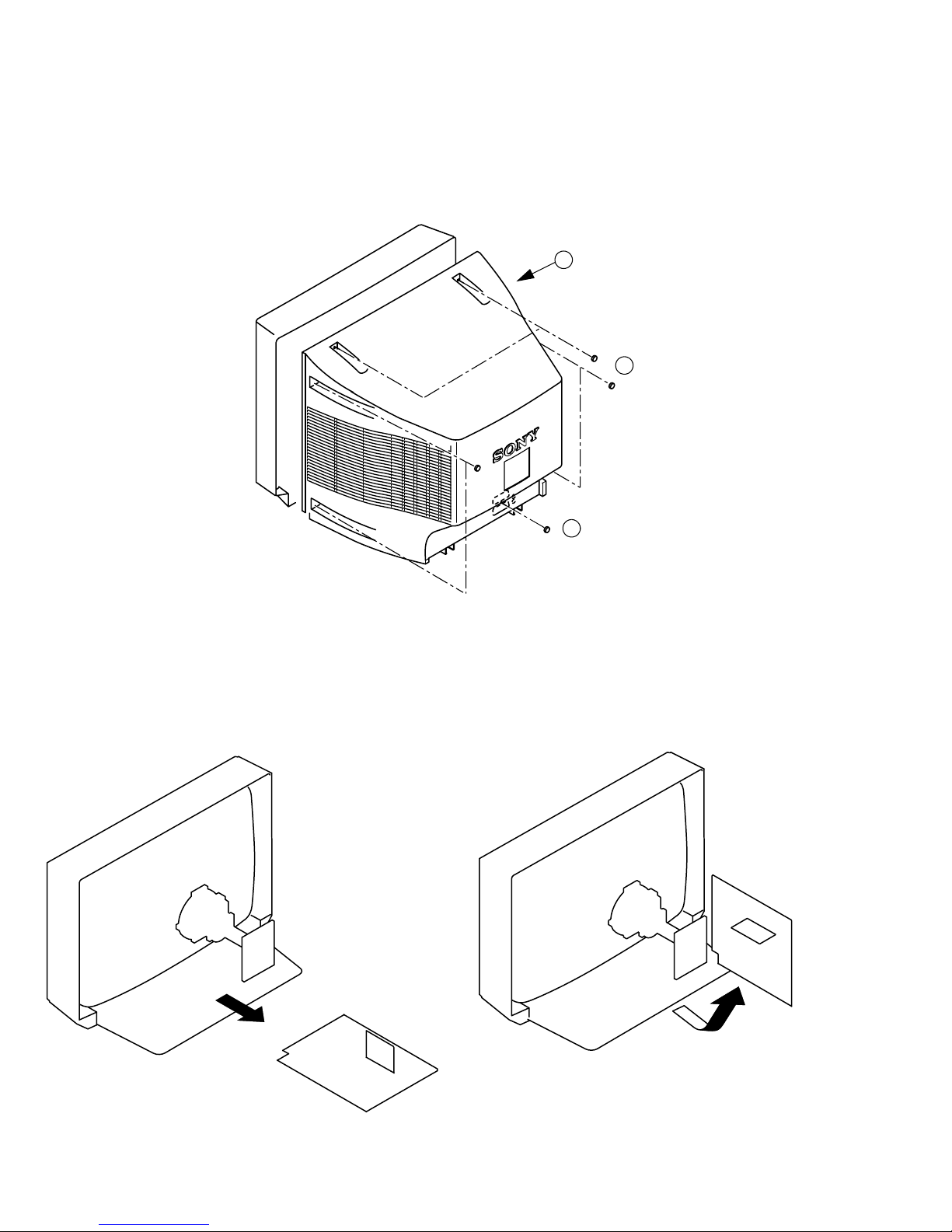
2-1. REAR COVER REMOVAL
SECTION 2
DISASSEMBLY
3 Rear Cover
2 6 Screws BTV 4x16
2-2. CHASSIS ASSY REMOVAL
1 1 Screw BTV 4x16
2-3. SERVICE POSITION
12
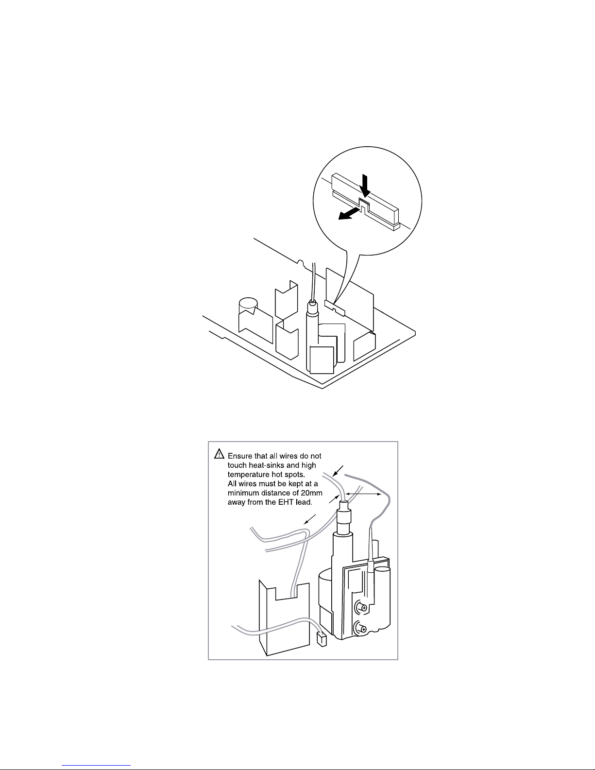
2-4. S1 BOARD REMOVAL
Release the clip indicated
>20mm
EHT Lead
>20mm
13

2-5. PICTURE TUBE REMOVAL
Two Band DGC holders 6
Degaussing coils 7
Spring Extension 8
CVM Board
Film neck assy 4
Deflection yoke
Anode cap 1
2 Chassis assy
3
5
9 Four PT screws (M)
10 Picture tube
Cushion
• REMOVAL OF ANODE-CAP
Note : Short circuit the anode of the picture tube and the anode cap to the metal chassis, CRT shield or carbon paint on the CRT, after removing the anode.
* REMOVING PROCEDURES.
c
a
1
Turn up one side of the rubber cap in
the direction indicated by the arrow a
• HOW TO HANDLE THE ANODE-CAP
1 To prevent damaging the surface of the anode-cap do not use sharp materials.
2 Do not apply too great a pressure on the rubber, as this may cause damage to the
anode connector.
3 A metal fitting called a shatter hook terminal is fitted inside the rubber cap.
Do not turn the rubber foot over excessively this may cause damage if the shatter
hook sticks out.
b
b
2 Using a thumb pull up the rubber cap
firmly in the direction indicated by the
arrow b
3 When one side of the rubber cap is
Anode button
separated from the anode button, the
anode-cap can be removed by turning
up the rubber cap and pulling it up in
the direction of the arrow c
14
15
Tab
Catch
CatchCatch
Catch
Catch
Tab
Tab
Tab
Tab
Refitting
Gate
Gate
Gate
Gate
GateGate
Gate Gate
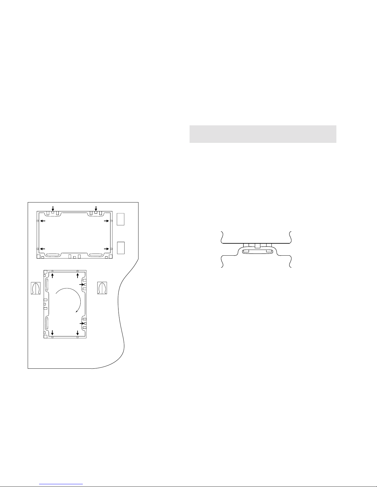
2-6.REMOVAL AND REPLACEMENT OF THE MAIN-BRACKET
BOTTOM PLATES.
(1) REMOVING THE PLATES
In the event of servicing being required to the solder side of the A Board printed
wiring board, the bottom plates fitted to the main chassis bracket require to be
removed.
This is performed by cutting the gates with a sharp wire cutter at the locations
shown and indicated by arrows.
Note :
There are 2 plates fitted to the main bracket and secured by 4 gates.
Only remove the necessary plate to gain access to the printed wiring board.
(2) REFITTING THE PLATES
Because the plates differ in size it is important that the correct plates are refitted in
their original location.
Please note that the plates need to be rotated 180 degrees from the cut position to
allow the tabs to be fitted in the catch positions.
£
For safety reasons, on no account should the plates be
removed and not refitted after servicing.
 Loading...