

Sony Trinitron KD-28DX51U, Trinitron KD-28DX51E, Trinitron KD-32DX51E, Trinitron KD-32DX51U Service Manual
- 1 -
SERVICE MANUAL
FE-2D
CHASSIS
MODEL
COMMANDER DEST CHASSIS NO.
KD-28DX51U
RM-949 UK SCC-Q52W-A
KD-28DX51E
RM-949 ESP SCC-R43A-A
KD-28/32DX51
RM-949
MODEL
COMMANDER DEST CHASSIS NO.
KD-32DX51U
RM-949 UK SCC-Q52V-A
KD-32DX51E
RM-949 ESP SCC-R43B-A

- 2 -
TABLE OF CONTENTS
Section Title Page Section Title Page
Caution .................... 3
Specifications .................... 4
Connectors .................... 5
Self Diagnostic Software .................... 6
1. GENERAL
Automatically Tuning the TV .................... 7
Finding your video channel .................... 7
Selecting digital and analogue
mode .................... 7
Everyday Use .................... 7
Digital Text .................... 8
Analogue Text .................... 8
The Digital electronic
programme guide (EPG) .................... 9
Using the TV menu system .................... 10
Digital Set-up Menu .................... 11
Digital Tuning Menu .................... 11
Connecting other Equipment to the TV ........ 12
Viewing pictures from a connected VCR ...... 12
Viewing pictures from equipment
connected to the rear sockets .................... 12
Viewing pictures from equipment
connected to the front sockets .................... 12
Lifting the TV set ............. 12
Specifications .................... 13
Troubleshooting .................... 13
2. DISASSEMBLY
2-1. Rear Cover Removal .................... 14
2-2. Chassis Removal and Refitting .................... 14
2-3. A Board Removal [Step 1] .................... 15
2-4. A Board Removal [Step 2] .................... 15
2-5. F3 Board Removal .................... 15
2-6. A1 Board Removal .................... 16
2-7. Service Position .................... 16
2-8. N Board Removal .................... 16
2-9. Picture Tube Removal .................... 17
Bottom Plates .................... 18
3. SET-UP ADJUSTMENTS
3-1. Beam Landing .................... 19
3-2. Convergence .................... 20
3-3. Focus Adjustment .................... 22
3-4. Screen (G2), White Balance .................... 22
4. CIRCUIT ADJUSTMENTS
4-1. Electrical Adjustments .................... 23
4-2. Test Mode 2 .................... 25
5. DIAGRAMS
5-1. Block Diagrams (1) .................... 26
Block Diagrams (2) .................... 27
Block Diagrams (3) .................... 28
5-2. Circuit Board Location .................... 29
5-3. Schematic Diagrams and
Printed Wiring Boards .................... 29
* A Board PWB .................... 30
* A Board Schematic .................... 31
* A1 Board PWB .................... 35
* A1 Boar d Schematic .................... 36
* H5 Board PWB .................... 39
* H5 Board Schematic .................... 38
* F5 Board PWB .................... 39
* F5 Board Schematic .................... 38
* F3 Board PWB .................... 39
* F3 Board Schematic .................... 38
* B1 Board PWB .................... 39
* B1 Board Schematic .................... 38
* C Board PWB .................... 41
* C Board Schematic .................... 40
* D2 Board PWB .................... 41
* D2 Board Schematic .................... 40
* VM Board PWB .................... 41
* VM Board Schematic .................... 42
5-4. Semiconductors .................... 43
5-5. IC Blocks .................... 45
6. EXPLODED VIEWS
6-1. Chassis .................... 46
6-2. Picture Tube .................... 47
7. ELECTRICAL PARTS LIST .................... 48
CAUTION
SHORT CIRCUIT THE ANODE OF THE PICTURE TUBE AND THE
ANODE CAP TO THE METAL CHASSIS, CRT SHIELD, OR THE
CARBON PAINTED ON THE CRT, AFTER REMOVAL OF THE
ANODE CAP.
WARNING !!
AN ISOLATION TRANSFORMER SHOULD BE USED DURING
ANY SERVICE WORK TO AVOID POSSIBLE SHOCK HAZARD
DUE TO LIVE CHASSIS, THE CHASSIS OF THIS RECEIVER IS
DIRECTLY CONNECTED TO THE POWER LINE.
SAFETY-RELATED COMPONENT WARNING !!
COMPONENTS IDENTIFIED BY SHADING AND MARKED
ON
THE SCHEMATIC DIAGRAMS, EXPLODED VIEWS AND IN THE
PARTS LIST ARE CRITICAL FOR SAFE OPERATION. REPLACE
THESE COMPONENTS WITH SONY PARTS WHOSE PART
NUMBERS APPEAR AS SHOWN IN THIS MANUAL OR IN
SUPPLEMENTS PUBLISHED BY SONY.
ATTENTION
APRES AVOIR DECONNECTE LE CAP DE’LANODE,
COURT-CIRCUITER L’ANODE DU TUBE CATHODIQUE ET
CELUI DE L’ANODE DU CAP AU CHASSIS METALLIQUE DE
L’APPAREIL, OU AU COUCHE DE CARBONE PEINTE SUR LE
TUBE CATHODIQUE OU AU BLINDAGE DU TUBE
CATHODIQUE.
ATTENTION !!
AFIN D’EVITER TOUT RISQUE D’ELECTROCUTION
PROVENANT D’UN CHÁSSIS SOUS TENTION, UN
TRANSFORMATEUR D’ISOLEMENT DOIT ETRE UTILISÈ LORS
DE TOUT DÈPANNAGE LE CHÁSSIS DE CE RÈCEPTEUR EST
DIRECTMENT RACCORDÈ Á L’ALIMENTATION SECTEUR.
ATTENTION AUX COMPOSANTS RELATIFS Á
LA SECURITÈ!!
LES COMPOSANTS IDENTIFIÈS PAR UNE TRAME ET PAR UNE
MARQUE
SUR LES SCHÈMAS DE PRINCIPE, LES VUES
EXPLOSÈES ET LES LISTES DE PIECES SONT D’UNE IMPORTANCE CRITIQUE POUR LA SÈCURITÈ DU FONCTIONNEMENT,
NE LES REMPLACER QUE PAR DES COMPSANTS SONY DONT
LE NUMÈRO DE PIÈCE EST INDIQUÈ DANS LE PRÈSENT
MANUEL OU DANS DES SUPPLÈMENTS PUBLIÈS PAR SONY.
- 3 -
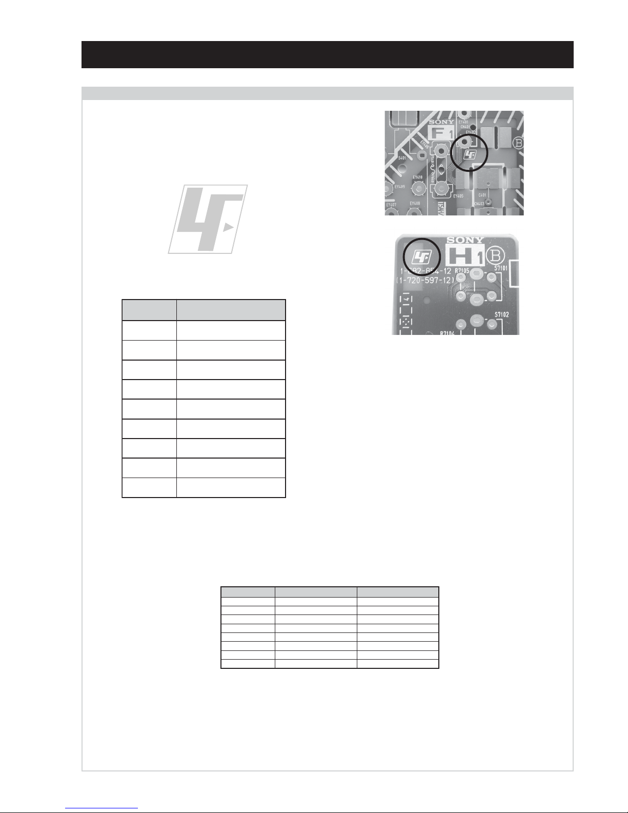
The circuit boards listed below [Table 1] used in these models may
have been processed using Lead Free Solder. The boards are
identified by the LF logo located close to the board designation e.g.
F1, H1 etc [ see examples ]. The servicing of these boards requires
special precautions to be taken as outlined below.
Table 1
CAUTION
Lead Free Soldered Boards
example 1
example 2
It is strongly recommended to use Lead Free Solder material in order to guarantee optimal quality of new solder joints. Lead Free Solder is
available under the following part numbers :
Due to the higher melting point of Lead Free Solder the soldering iron tip temperature needs to be set to 370 degrees centigrade. This requires
soldering equipment capable of accurate temperature control coupled with a good heat recovery characteristics.
For more information on the use of Lead Free Solder, please refer to http://www.sony-training.com
rebmuntraP retemaiD skrameR
91-500-046-7mm3.0gK52.0
02-500-046-7mm4.0gK05.0
12-500-046-7mm5.0gK05.0
22-500-046-7mm6.0gK52.0
32-500-046-7mm8.0gK00.1
42-500-046-7mm0.1gK00.1
52-500-046-7mm2.1gK00.1
62-500-046-7mm6.1gK00.1
draoB noitcnuF
AoiduA,oediV,noitcelfeD,ylppuSrewoP
1AgnissecorPdnEtnorFlatigiD
1BgnihctiwSV,U,Y
CtuOB,G,R
2DnoitcelfeDedoMtramS
3FsretliFeniL,esuF,egrahcsiDgninthgiL
5FSCRIS,DEL,tupnICA
5HonohPdnaSHVS,enohpdaeH
MVnoitaludoMyticoleV

- 4 -
How to replace the fuse.
Open the fuse compartment with
a screwdriver blade and replace
the fuse.
FUSE
WARNING (UK Models only)
The flexible mains lead is supplied connected to a B.S. 1363 fused
plug having a fuse of 5 AMP rating. Should the fuse need to be
replaced, use a 5AMP FUSE approved by ASTA to BS 1362, ie one
that carries the
ASA
T
mark.
IF THE PLUG SUPPLIED WITH THIS APPLIANCE IS NOT SUITABLE FOR THE OUTLET SOCKETS IN YOUR HOME, IT SHOULD
BE CUT OFF AND AN APPROPRIATE PLUG FITTED. THE PLUG
SEVERED FROM THE MAINS LEAD MUST BE DESTROYED AS A
PLUG WITH BARED WIRES IS DANGEROUS IF ENGAGED IN A
LIVE SOCKET.
When an alternative type of plug is used, it should be fitted with a
5 AMP FUSE, otherwise the circuit should be protected by a 5AMP
FUSE at the distribution board.
LEDOMMETI metsySnoisiveleT metsySoeretS egarevoClennahC metsySroloC
UT-BVD,IoeretSMACIN96B-12B:FHU
LAP
34.4CSTN,85.3CSTN
)NIOEDIV(
LM@PM2-GEPM
ET-BVD,K/D,H/G/BoeretSMACIN
30S-10S,21R-1R,21E-2E:FHV
96R-12R,96E-12E:FHU
02S-10S:VTELBAC
14S-12S:REPYH
LAP
34.4CSTN,85.3CSTN
)NIOEDIV(
LM@PM2-GEPM
emaNledoM
metI
U15XD82-DK
~
U15XD23-DK
E15XD82-DK
~
E15XD23-DK
bmoClaPFFOFFO
PIPFFOFFO
ytiroirPBGRNONO
xoBrefooWFFOFFO
1tracSNONO
2tracSNONO
)3(nitnorFNONO
4tracSFFOFFO
rotcejorPFFOFFO
G/BmroNFFONO
ImroNNOFFO
K/DmroNFFONO
SUAmroNFFOFFO
LmroNFFOFFO
TASmroNFFOFFO
MmroNFFOFFO
txeteleTNONO
oeretSmaciNNONO
ebuTerutciP
tuptuodnuoS
nortinirTDFyalpsiDtalF
)sehcni82(mc17xorppA
derusaemerutcipmc66xorppA(
15XD82-DK)yllanogaid
)sehcni23(mc28xorppA
derusaemerutcipmc67xorppA(
15XD23-DK)yllanogaid
rekaepstfeLdnathgiR)SMR(W7x2)rewoPcisuM(W41x2
]RAER[slanimreTtuptuO/tupnI snoitacificepSlareneG
rotcennocoruEnip-12:1
)dradnatsCELENEC(
.slangisoediVdnaoiduArofstupnI
.BGRrofstupnI
oiduAdnaoediVVTfostuptuO
.slangis
stnemeriuqeRrewoPV042-022
noitpmusnoCrewoP
)15XD82-DK(W08
)15XD23-DK(W88
rotcennocoruEnip-12:2
.slangisoediVdnaoiduArofstupnI
.oediVSrofstupnI
.slangisoiduAdnaoediVVTfostuptuO
)elbatceles(
snoisnemiD
)15XD82-DK(mm345x694x487xorppA
)15XD23-DK(mm885x575x598xorppA
thgieW
)15XD82-DK(gk44xorppA
)15XD23-DK(gk16xorppA
skcaJonohPoiduArofelbairavsrotcennoCtuptuO
slangiS
seirosseccAdeilppuS
)1(rednammoCetomeR949-MR
)2(yrettab6RdetangisedCEI
daeLFR
latigiD
kcaJmedoM
AICMCP
serutaeFrehtO
,kniltramS,FD&PQD,noitcudeResioNotuA
,dnuosdnuorrusybloDlautriV,srenuTowT
.IUG5.2VTDI,txetlatigidsuoenatnatsni-raen
]TNORF[slanimreTtuptuO/tupnI lortnoCderarfnI:metsySlortnoCetomeR
kcajenohpdaeHkcajinimoerets
stnemeriuqerrewoP
cdV3
noitangisedCEIseirettab2
)AAezis(6R
stupnioiduAskcajonohp
stupnioediVskcajonohp
tupnioediVSNIDnip4
.ecitontuohtiwegnahcottcejbuserasnoitacificepsdnangiseD

- 5 -
21 pin connector
19
17
15
13
11
9
7
5
3
1
20
18
16
14
12
10
8
6
4
2
21
Rear Connection Panel Front Connection Panel
noitarugifnocniptekcosoediVS
niP
oN
langiS leveLlangiS
1dnuorG-
2dnuorG-
3tupni)langisS(Y,mho57Bd3-/+V1
V3.0.cnySevitisop
Bd01+3-
4tupni)langisS(CBd3-/+V3.0
evitisop,mho57
.cnyS
S-Video
socket
Connected Not Connected (open) * at 20Hz - 20kHz
Pin No 1 2 4 Signal Signal level
1 Audio output B
(right)
Standard level : 0.5V rms
Output impedence : Less than 1kohm*
2
Audio input B
(right)
Standard level : 0.5V rms
Output impedence : More than 10kohm*
3
Audio output A
(left)
Standard level : 0.5V rms
Output impedence : Less than 1kohm*
4 Ground (audio)
5 Ground (blue)
6 Audio input A
(left)
Standard level : 0.5V rms
Output impedence : More than 10kohm*
7 Blue input 0.7 +/- 3dB, 75 ohms positive
8 Function select
(AV control)
High state (9.5-12V) : Part mode
Low state (0-2V) : TV mode
Input impedence : More than 10K ohms
Input capacitance : Less than 2nF
9 Ground (green)
10 Open
11 Green Green signal : 0.7 +/- 3dB, 75 ohms,
positive
12 Open
13 Ground (red)
14 Ground (blanking)
15
_ _ Red input 0.7 +/- 3dB, 75 ohms, positive
_ (S signal Chroma
input)
0.3 +/- 3dB, 75 ohms, positive
16 Blanking input
(Ys signal)
High state (1-3V) Low state (0-0.4V)
Input impedence : 75 ohms
17 Ground (video
output)
18 Ground (video
input)
19 Video output 1V +/- 3dB, 75ohms, positive sync 0.3V
(-3+10dB)
20
_ _ Video input 1V +/- 3dB, 75ohms, positive sync 0.3V
(-3+10dB)
_ Video input
Y (S signal)
1V +/- 3dB, 75ohms, positive sync 0.3V
(-3+10dB)
21 Common ground
(plug, shield)
- 6 -
FE-2D SELF DIAGNOSTIC SOFTWARE
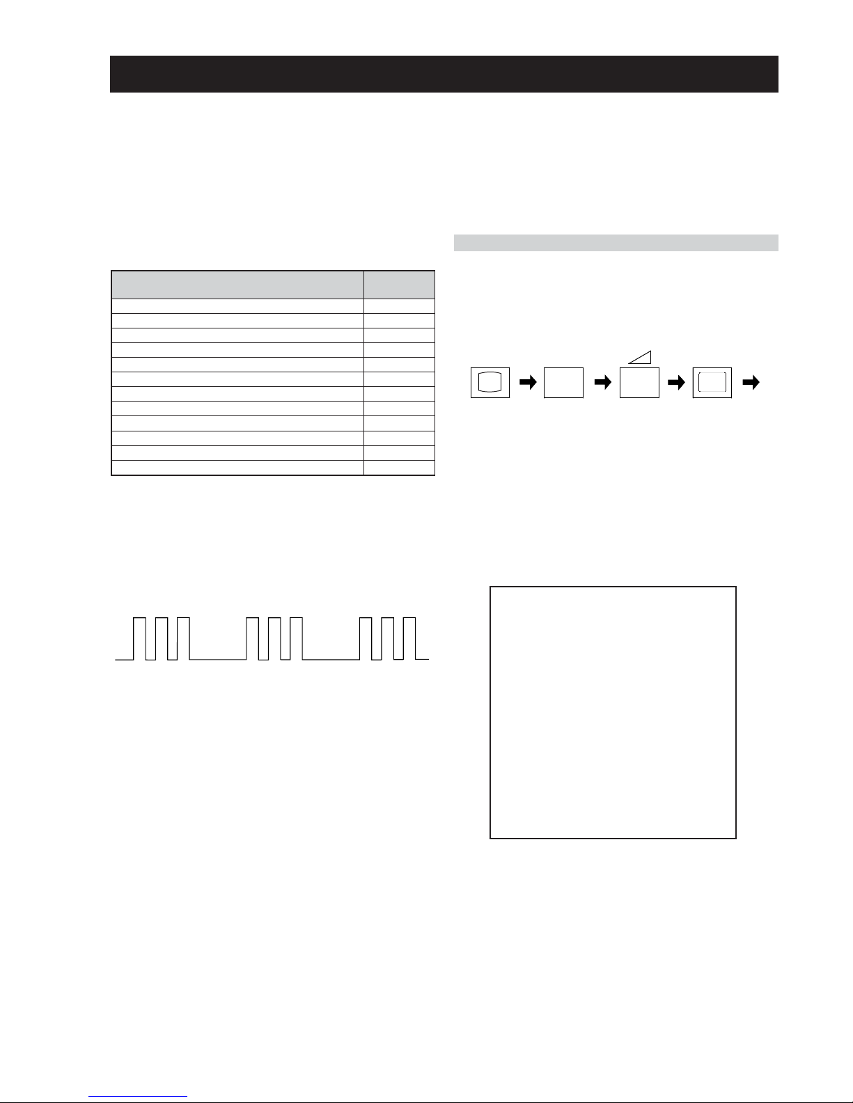
The identification of errors within the FE-2D chassis is triggered in one of two ways :- 1: Busy or 2: Device failure to respond to IIC. In the
event of one of these situations arising the software will first try to release the bus if busy (Failure to do so will report with a continuous
flashing LED) and then communicate with each device in turn to establish if a device is faulty. If a device is found to be faulty the relevant
device number will be displayed through the LED (Series of flashes which must be counted) See table 1., non fatal errors are reported using this
method.Each time the software detects an error it is stored within the NVM. See Table 2.
Flash Timing Example : e.g. error number 3
StBy LED
ON
ON ON
OFF
OFF
Table 1
How to enter into Table 2
1. Turn on the main power switch of the TV set and enter into
the ‘Standby Mode’.
2. Press the following sequence of buttons on the Remote
Commander.
i+
5
-
(ON SCREEN (DIGIT 5) (VOLUME -) (TV)
DISPLAY)
3. The following table will be displayed indicating the error
count.
Table 2
Note: To clear the error count data press ‘80’ on the Remote
commander.
egasseMrorrE
DEL
edoC
rorreoN00
devreseR10
)noitcetorPtnerruCrevO(PCO20
desUtoN30
cnySlacitreVoN40
norewoptarorrERKI50
norewoptawolsenilatadro/dnakcolcsubCII60
norewoptaegdelwonkcasubCIIonMVN70
desUtoN80
norewoptaegdelwonkcaonrenuT90
rorrErossecorPdnuoS01
rorrestlov8rellortnocelgnuJ11
UNEMRORRE
:20E
:30E
:40E
:50E
:60E
:70E
:80E
:90E
:01E
:11E
:21E
:31E
:41E
EMITGNIKROW
SRUOH
SETUNIM
PCO
A/NPVO
CNYSV
RKI
CII
MVN
ELGNUJ
RENUT
PDNUOS
V8
AMME
XETROP
CTR
)552,0(
)552,0(
)552,0(
)552,0(
)552,0(
)552,0(
)552,0(
)552,0(
)552,0(
)552,0(
)552,0(
)552,0(
)552,0(
0
0
0
0
0
0
0
0
0
0
0
0
0
1
22
- 7 -
9
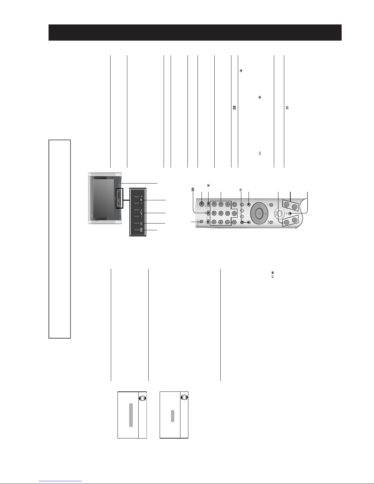
Everyday use
This section explains the various functions and operations used during everyday
viewing. Most operations can be done using the remote control.
1.
Press the On/Off button (labelled !) on the front of the TV to switch
on the TV.
When the TV is in standby mode (the 1 indicator on the TV is lit red),
press the TV I/1 button on the remote control to switch on the TV.2.Press the PROG+/- buttons on the TV or press the PROG+/- or
Numbered buttons on the remote control to select a TV channel.
When selecting double digit numbers using the Numbered buttons, enter
the second digit within two seconds.
3.
Press the 2 +/- buttons on the TV or on the remote control to adjust the
volume.
Additional operations
To Press
Turn off the TV temporarily
(standby)...
TV I/1 on the remote control. When
the TV is in standby mode the 1
indicator on the TV is lit red. Press
again to return to normal TV operation.
Mute the sound... % button on the remote control. Press
again to cancel.
Select digital mode... DIGITAL button.
If the TV is in digital mode an
information banner appears briefly on
screen when you change channels.
Select analogue mode ... a button.
If the TV is in analogue mode the
channel number appears in green
lettering when you change channels.
Change the Screen Mode... button. Refer to page 10.
Watch pictures from equipment
connected to the TV’s front and rear
sockets (video input mode)...
t button on the TV or t/ button
on the remote control repeatedly until
the picture appears. Refer to page 26.
z For example, if you wish to view pictures from a DVD player connected to the i1/
socket on the rear of the TV, press the
t/ button repeatedly until the t1
symbol appears on the TV screen together with the DVD picture.
Please note, most equipment connected by scart lead, when activated, will send
a signal to the TV. The TV will automatically display the picture for you.
Access text services (depending on
availability of serv ice)...
/ button on the remote control.
Refer to pages 12 and 13.
Access the Digital Electronic
Programme Guide (EPG)...
button on the remote control.
Refer to page 14.
On/Off
button
PROG +/-
buttons
2 +/-
buttons
Autotune
button
3 3
o4
% button
PROG +/-
buttons
2 +/-
buttons
Numbered
buttons
t/
button
TV I/1
button
button
/
button
button
DIGITAL button
Basic Operation
t
button
6
1.
When you switch on the TV for the first time a language menu appears
on screen with the word ‘English’ highlighted. Press the V or v buttons on
the remote control to highlight the language you require then press the
OK button to confirm. From now on all menus appear in your chosen
language.
2.
The picture rotation prompt now appears asking you to check if the
picture is slanted. (Sometimes the Earth’s natural magnetism can cause
the screen to look slanted.)
a) If no correction is required, press the V or v button to highlight ‘Not
necessary’. Press the OK button to continue.
b) If some correction is required, press the V or v button to highlight
‘Adjust now’. Press the OK button to continue. Press the V or v button
to correct the slant. Press the OK button to store.
3.
The autotune prompt appears. Press the OK button to select ‘Yes’. The
autotune procedure begins.
The digital autotune display appears on screen and the TV starts to
search for all the available digital channels. This may take some time,
please be patient and do not press any buttons on the TV or remote
control.
When the digital autotune is complete, the analogue autotune starts to
search for all the available analogue channels.
If no digital or analogue channels are found, a message appears asking
you to confirm that the aerial is connected correctly. Check all the aerial
connections and press the OK button to start the autotune procedure
again.
Once all available digital and analogue channels have been stored, the
TV returns to normal operation, displaying the digital channel stored on
programme number 1. If no digital channels are found, the analogue
channel stored on programme number 1 is displayed.
The TV has now tuned
in all the available channels
1.
If you have connected a VCR to your TV when following the ‘Connecting
an aerial and a VCR to the TV’ instructions, you now need to find your
video channel. Press the PROG+/- button until the picture from the pre-
recorded tape appears on screen.
If you have connected your VCR using a scart lead, press the /
button repeatedly until the picture from the pre-recorded tape appears on
screen.
1.
Press the DIGITAL button to switch to digital mode.
In digital mode, an information banner appears briefly on screen when
you change the TV channels.2.Press the a button to switch to analogue mode.
In analogue mode, the channel number appears in green lettering when
you change the TV channels.
Automatically tuning the TV
5
Finding your video channel
6
The ‘Picture Rotation’ menu.
The ‘Autotune’ prompt.
Do you want to start
automatic tuning?
Ye s
No
OK
If picture slants, please
adjust picture rotation
Not necessary
Adjust now
OK
Selecting digital and analogue mode
7
Getting Started
The operating instructions mentioned here are partial abstracts from the ‘Operating
Instruction Manual’. The page numbers of the ‘Operating Instruction Manual’ remain
as in the manual.
SECTION 1 GENERAL
- 8 -
12
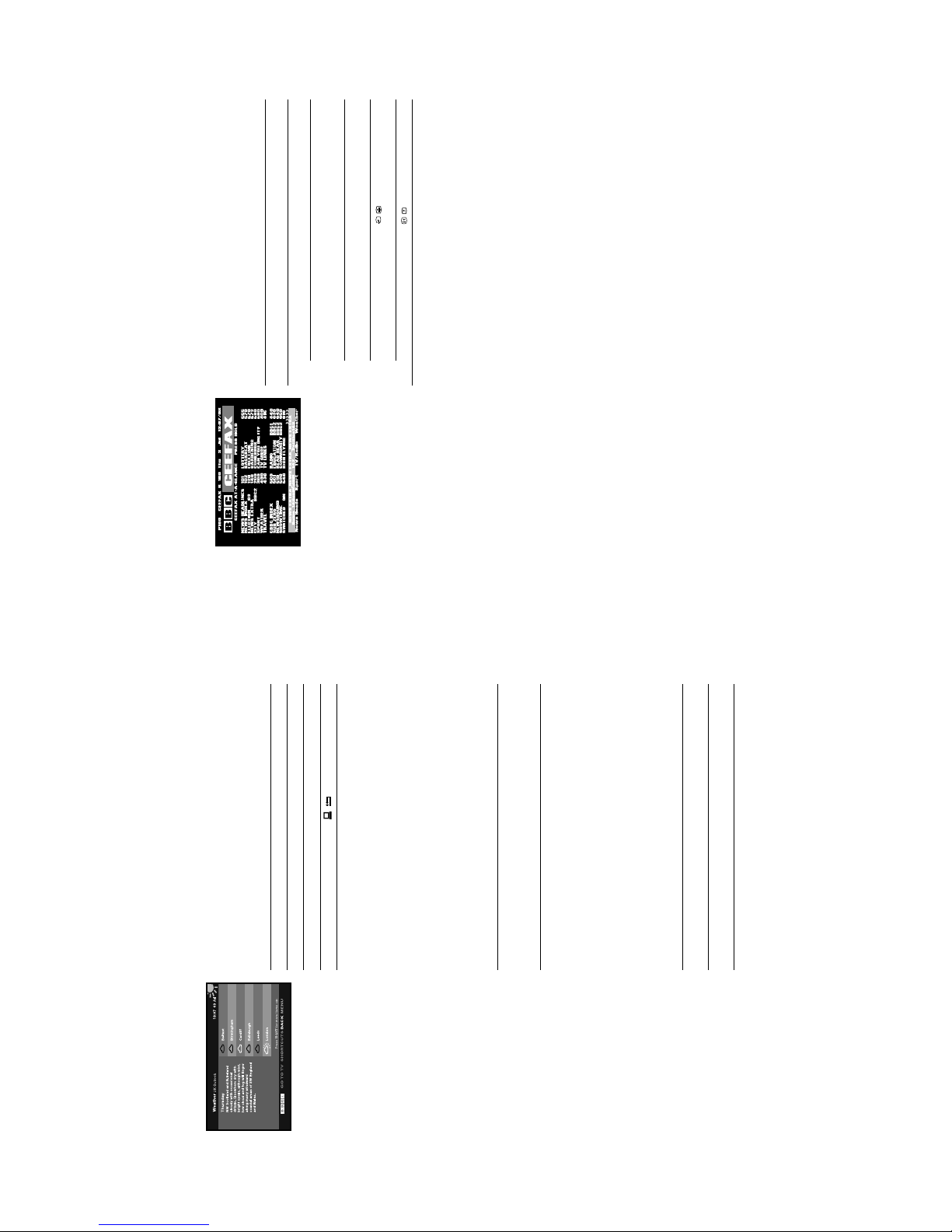
Digital text
Many broadcasters now provide a digital text service. Digital text services offer all
the familiar information that analogue (conventional) text services provide but with
the look and feel of a graphically rich website.
The appearance, content and navigation methods of all digital text services are
decided by the broadcaster. For example, digital text from the BBC may look
different from digital text from ITV. Most of the digital text services currently
available use simple navigation methods based on the following buttons:
Viewing digital text
There are two ways to view digital text, either while watching a digital channel or by
accessing a dedicated digital text channel.
a) Digital text from digital channels
(depending on availability of service)
b) Digital text from a dedicated digital text channel
(depending on availability of service)
Some broadcasters provide a separate channel for accessing their digital text
service.
To Press
Load or exit digital text... / button.
Move around the screen... V, v, B or b buttons.
Select items on screen... OK and Numbered buttons.
Cancel a selection/go back a step... / button.
Access shortcuts... Coloured buttons.
1.
Select a digital channel which provides a text service.2.Press the / button to access the digital text service.3.Follow the on screen instructions.4.Once the text information is displayed, you can access the required
information by using the V, v, B or b buttons, the coloured buttons and/
or the numbered buttons on the remote control. If you are instructed to
press ‘OK’ or ‘Select’ when viewing the text pages, press the OK button.
5.
When you have finished viewing the text service, press the / button to
exit.
1.
Select the programme number that is broadcasting the dedicated digital
text channel by using the numbered buttons on the remote control. If you
do not know the channel number of a dedicated digital text channel, you
can use the ‘EPG menu’ to find one (please refer to the ‘EPG’ section of
this manual).2.Once the text page is displayed, follow the on-screen instructions to
obtain your required selection.3.If you are instructed to press ‘OK’ or ‘Select’ when viewing the text pages,
press the OK button.4.When you have finished viewing the text service, press the / button to
return to the text front page, or press the PROG+/- button to return to
normal TV operation.
An example of digita l text.
Basic Operation
13
Analogue text
Most analogue TV channels broadcast a text service. The index page (usually page
100) provides information on how to use the service. Please ensure that you are
receiving a good signa l, or some text errors may occu r.
Viewing analogue text
Fastext
Fastext allows you to access pages quickly and easily. When Fastext is available,
four coloured items appear at the bottom of the text page. Press the corresponding
Coloured button on the remote control to access the page.
1.
Select an analogue channel that provides a text service.2.Press the / button to access the text service.
3.
To Press
Select a page... Numbered buttons. (Press the
PROG +/- buttons to display the
previous or next page).
Superimpose the text over the TV
picture (mix mode)...
/ button. Press again to exit the
text service.
Hold a page... / button. Press again to
cancel.
Reveal hidden information... / button.4.Press the / button to return to normal TV operation.
An example of analogue text.
Basic Operation

- 9 -
14
The Digital Electronic
Programme Guide
(EPG)
The Digital Electronic Programme Guide (EPG) allows you to:
a) view programme information for all digital channels,
b) sort programme information by category,
c) set reminders for the TV to automatically switch to a programme when it starts,
d) record programmes
The EPG is only available in digital mode.
The Category pop-up list
The Category pop-up list allows you to display channels in the EPG by category.
The categories available include:
Recording
1.
With the TV in digital mode, press the button to display the EPG.
2.
To Press
Move around the menu... V, v, B and b buttons.
Display the previous/next five
channels in the list...
RED button (previous), GREEN
button (next).
3.
Press the button to return to normal TV operation.
Favourite Contains all the channels you have stored as a favourite
(see previous pag e).
All Categories Contains all available channels.
News Contains all news channels.
1.
With the EPG on screen, press the BLUE button.2.Press the V, v, B or b buttons to highlight the required category.3.Press the OK button. The EPG now only shows channels from the
category selected. The category name is displayed at the top of the
channel list.
1.
With the EPG menu on screen, press the V, v, B or b button to highlight
a future programme.
2.
Press the YELLOW button to display the Timer menu. This menu offers
the following options:
a) Timer REC*
Highlight ‘Timer REC’ and press the OK button to automatically set your
VCR to record the selec ted programme.
b) Reminder**
Highlight ‘Reminder’ and press OK if you wish your selected future
programme to automatically appear on screen when transmission starts.
When you use this option the timer symbol * appears in the display. If you
are watching another programme just before the transmission is due to
begin, the TV will automatically switch to your selected programme.
*For Smartlink VCRs only. If your VCR does not
have Smartlink a message will be displayed to
inform you. Press the RED button to set t he TV
timer. You will now have to manually set your
VCR timer.
When a programme has been set to record, a
solid red bar appears under the time bar in the
EPG for that programme, and the record symbol
* appears in the display. The coloured bar shows
the time allocated for recording and reminds you
that you are unable to record other programmes
during that time period.
Once a recording has begun you can put the TV
into standby mode, but do not switch off
completely or the recording may be cancelled.
**If you have placed the TV into standby, it will
automatically turn itself on when the ‘Reminder’
programme is about to start. If the TV receives
no command, it will return to the standby mode.
*If you have set a Parental Control age limit in the
Main Menu, and the programme exceeds that
limit, you will be asked to enter your PIN before
the preview is allowed. Programmes that exceed
the age limit are identified by a symbol.
Initially the PIN code is preset to 1234. Refer to
‘PIN Code’ on page 20 for more information.
The ‘Digital EPG’.
Advanced Operation
The ‘Category pop-up list’.
15
To cancel a recording
The Timer pop-up menu also has a ‘Timer list’ option. This list appears only after
you have set a prog ramme to record or to wake up. If you hig hlight ‘Timer list’ an d
press the OK button, a screen is displayed showing all the programmes you have
set for recording or wake up. To delete one of these programmes, proceed as
follows:
c) Manual timer REC***
Highlight ‘Manual timer REC’ and press OK if you wish to record a future
programme. The Manual Timer display appears.
Press the V or v button to set the day of recording, then press the b
button to move to the start time. Repeat this procedure to set the start and
stop times and the channel number, then press the OK button to store
and return to the EPG menu.
Press the button to remove the EPG menu. Unless you have a
SMARTLINK VCR, you must now set the timer recording function of your
VCR to switch on and off to correspond with the programme you have
stored for recording.
Press the OK button to display the ‘Timers’ menu.
1.
Press the V or v button to highlight the programme you wish to delete.2.Press the OK button to confirm deletion.3.Press the button when you wish to return to normal TV operation.
***The ‘Manual timer REC’ feature only works if
you have connected your VCR to the AV2 socket
i2/r on the rear of the TV. After you have
programmed a recording you can put the TV into
standby mode, but do not switch off completely
or the recording will be cancelled. If you put the
TV into standby mode, the standby indicator on
the front of the TV flashes green periodically to
remind you a recording has been programmed.
Advanced Operation
- 10 -
17
Using the TV menu
system
Use the following buttons to operate the TV menu system.
The individual menus are explained on the following pages.
Picture Adjustment menu
1.
To Press
Access the TV menu system... MENU button.
Highlight an option... V or v buttons.
Enter the highlighted menu or
option...
b button.
Return to the last menu or option... B button.
Alter the settings of a selected
option...
V, v, B or b buttons.
Store settings/changes... OK button.2.Press the MENU button to return to normal TV operation.
Mode
This option allows you to choose between three picture mode settings, ‘Live’,
‘Movie’ and ‘Personal’.
With the ‘Mode’ option highlighted, press the b button to ad just. Press the V or
v button to select the required mode. Press the OK button to confirm.
Contrast, Brightness, Colour, Sharpness, Hue
These options allow you to adjust the contrast, brightness, colour, sharpness
and hue.
‘Sharpness’ is not adjustable in digital mode. ‘Hue’ is only available when
viewing an NTSC colour signal, e.g. USA video tapes.
With the required option highlighted, press the b button to adjust. Press the B or
b button to set the level. Press the OK button to confirm.
Reset
This option resets all picture settings to the factory preset levels.
With the ‘Reset’ option highlighted, press the OK button to restore default picture
settings.
OK
button
V, v, B, and b
buttons
MENU
button
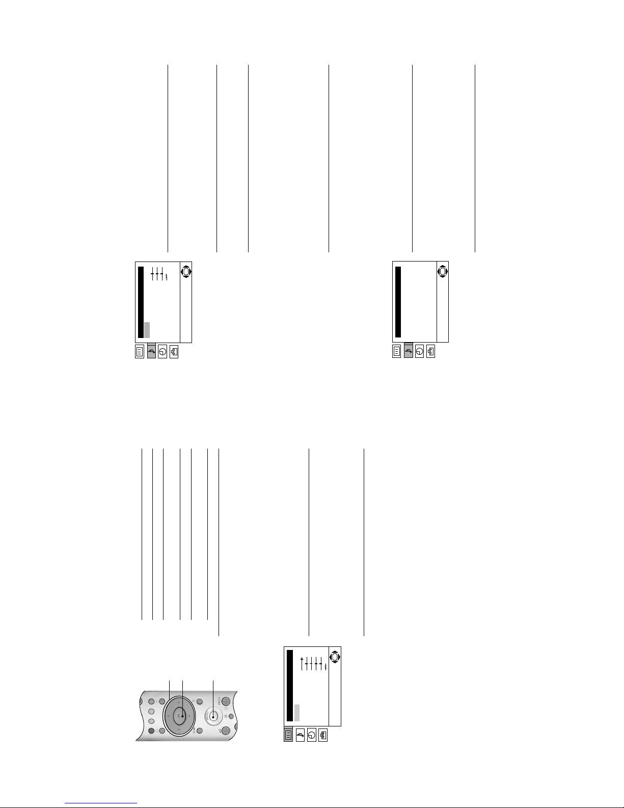
The ‘Picture Adjustment’ menu.
Picture Adjustment
Mode: Personal
Contrast
Brightness
Colour
Sharpness
Hue
Reset
OK
Advanced Operation
18
Sound Adjustment menu
Detail Adjustment menu
Mode
This option allows you to choose between four sound mode settings, ‘Personal’,
‘Rock’, ‘Pop’ and ‘Jazz’. ‘Rock’, ‘Pop’ and ‘Jazz’ are preset and only the
‘Balance’ setting can be adjusted. ‘Personal’ mode however, also allows you to
adjust the ‘Treble’ and ‘Bass’ settings.
With the ‘Mode’ option highlighted, press the b button to ad just. Press the V or
v button to select ‘Personal’, ‘Rock’, ‘Pop’ or ‘Jazz’. Press the OK button to
confirm.
Treble, Bass, Balance,
These options allow you to adjust the treble, bass, and balance.
‘Treble’ and ‘Bass’ can only be adjusted when the sound ‘Mode’ is set to
‘Personal’.
With the required option highlighted, press the b button to adjust. Press the B or
b button to set the level. Press the OK button to confirm.
Reset
This option resets all sound settings to the factory preset levels.
With the ‘Reset’ option highlighted, press the OK button to restore default sound
settings.
Dual Sound
When receiving a bilingual broadcast, this option allows you to choose
which language to listen to:
With the ‘Dual Sound’ option highlighted, press the b button to adjust.
Press the V or v button to select ‘Stereo’ to listen to the sound in stereo,
‘A’ to listen to the first language or ‘B’ to listen to the second language.
Press the OK button to confirm.
When receiving a stereo broadcast, this option allows you to choose
between mono and stereo sound:
With the ‘Dual Sound’ option highlighted, press the b button to adjust.
Press the V or v button to select ‘Mono’ or ‘Stereo’. Press the OK button
to confirm.
Detail Adjustment
This option displays the ‘Detail Adjustment’ menu (see below).
With the ‘Detail Adjustment’ option highlighted, press the OK button to display
the ‘Detail Adjustment’ menu.
Dolby Virtual*
This option simulates the full effects of Dolby Pro Logic Surround sound without
the need for additional speakers.
With the ‘Dolby Virtual’ option highlighted, press the b button to adjust. Press the
V or v button to select ‘On’ or ‘Off’. Press the OK button to confirm.
Auto Volume
Sometimes the broadcast volume level changes (e.g. adverts tend to be louder
than programmes). This option allows you to cancel out this effect, giving a
constant volume level.
Auto Volume is automatically switched to ‘Off’ when the sound ‘Mode’ is set to
‘Dolby Virtual’.
With the ‘Auto Volu me’ option highlighted, pr ess the b button to adjust. Press the
V or v button to select ‘On’ or ‘Off’. Press the OK button to confirm.
TV Speakers
This option allows you to switch off the TV’s internal speakers (e.g. when using
an external amplifier/surround sound system).
With the ‘TV Speakers’ option highlighted, press the b button to adjust. Press
the V or v button to select ‘On’ or ‘Off’. Press the OK button to store.
Detail Adjustment
Dolby Virtual:
Auto Volume:
TV Speakers:
OK
On
Off
On
The ‘Sound Adjustment’ menu.
The ‘Detail Adjustment’ menu.
*Manufactured under licence from Dolby
Laboratories. ‘Dolby’, ‘Pro Logic’ and the double-
D ; symbol are trademarks of Dolby
Laboratories.
Sound Adjustment
Mode: Personal
Treble
Bass
Balance
Reset
Dual Sound: Stereo
Detail Adjustment
OK
Advanced Operation

- 11 -
22
Digital Set Up menu
This menu gives you access to the digital features of this TV. The features available
are:
Subtitle Setting
This feature allows you to place digital subtitles on the screen. With ‘Subtitle
Setting’ highlighted, press b button to enter. Press the V or v button to select
‘Off’, ‘Basic’ or ‘Hard of Hearing’. Press OK button to confirm your choice.
Note:
When ‘Hard of Hearing’ is selected, some visual aids may also be displayed with the
subtitles. This will depend on the broadcaster, and may not always be available.
Subtitle Language
This allows you to select which language you want the subtitles to appear in on
screen. With ‘Subtitle Language’ highlighted, press b button to enter. Press the
V or v button to choose the desired language, then press OK button to confirm.
Audio Language
On some digital channels, the broadcaster may transmit several audio
languages for a programme. With ‘Audio Language’ highlighted, press b button
to enter. Press the V or v button to select the audio language you wish to hear,
then press OK to confirm.
Audio Type
With this option selected, the customer can change the level of audio sound for
the TV. With ‘Audio Type’ highlighted, press b button to enter. Press the V or v
button to select ‘Basic’ or ‘Hard of Hearing’ then press OK to confirm.
Parenta l lock
This feature allows you to set an age limit above which a PIN is required before
viewing is allowed.
1. With ‘Parental Lock’ highlighted, press b button to enter. The Parental L ock
display appears.
Note:
If you have not previously set a PIN, a display appears to inform you. Press OK to
display the ‘New PIN’ screen. Refer to ‘PIN Code’ feature to set a PIN for the first time.
2. Enter your existing PIN using buttons 0 - 9.
3. The ‘Age’ box now becomes active. Press the v or V button to set the age
limit desired, or set to ‘None’ for unrestricted viewing. Press OK to confirm.
4.Press B button to return to the Digital Settings menu.
PIN Code
This feature allows you to change your PIN code, or to set a PIN for the first
time.
1. With ‘PIN Code’ highlighted, press b button to display the PIN setting
screen.
If you have previously set a PIN: Use the butto ns 0 - 9 to enter your
existing PIN. Once correct PIN is entered the New PIN entry screen is
displayed.
If you have not set a PIN: Use the buttons 0 - 9 to enter the default PIN of
9999. The New PIN entry screen is displayed.
2. Using the buttons 0 - 9 enter your new PIN.
3. As requested, enter new PIN again as confirmation. A message appears to
inform you that your new PIN has been accepted.
4.Press B button to return to the Digital Settings menu.
Subtitle Language
Audio Language
Audio Type
Parental Lock
PIN Code
Technical Set-up
CA Module Set-up
Personal
Subtitle Setting
Digital Set-up
Personal
Off
Select:Back Enter:
OK
English
English
Basic
The ‘Digital Set Up’ menu.
Advanced Operation
23
Programme List Edit
Digital Manual Tuning
Personal
Digital Auto Tuning
Digital Tuning
Personal
Off
Select:Back Enter:
OK
English
English
Basic
Digital Tuning menu
With this menu you can manually or automatically tune in digital channels, and
rearrange the order in which they are stored on the TV if you wish.
Technical Set-up
This menu offers 3 further options, namely:
i) Auto Service Update
When enabled, this feature will detect any new digital service as it becomes
available, and will automatically add it to your programme list. With ‘Auto Service
Update’ highlighted, press b button to enter. Press the v or V button to set to
‘On’ or ‘Off’. Press OK button to confirm.
ii) Software Download
This allows the TV to automatically upgrade its software when a new version
becomes available. Sony recommends this option is s et to ‘On’ at all times. With
‘Software Download’ highlighted, press b button to enter. Press the v or V button
to set to ‘On’ or ‘Off’. Press OK button to confirm. When set to ‘On’ any new
operating software is automatically downloaded when released. If you do not
wish to receive software upgrades, set this option to ‘Off’.
iii) System Information
This feature allows you to view information regarding the software version and
the signal level of the channel as indicated by the coloured bar in the display.
With ‘System Information’ highlighted, press the b button to display the System
Information screen. Press B button to return to the Digital Settings menu.
CA Module Set-up
This feature is for future use only.
Digital Auto Tuning
All the available channels were tuned in when the TV was first installed. This
option allows you t o repeat that process (e g to re-install the TV at an alternativ e
location or search for new channels that have been launched by broadcasters).
With ‘Digital Auto Tuning’ highlighted, press b button to select. The autotune
prompt appears on screen. Press OK to start the auto tuning process. When an
on screen message informs you autotune has ended, press the B button to
return to the Digital Tuning menu.
Programme List Edit
This option allows you to change the order in which the channels are stored on
the TV, or delete unwanted channels. With the ‘Programme List Edit’ option
highlighted, press the b button to select. Press the V or v button to highlight the
channel you wish to move to a new position, then press b to select (or press the
OK button if you wish to delete the channel). Press the V or v button to highlight
the new position for your channel, then press the OK button. Your chosen
channel has now moved to the new position. Repeat to move other channels if
required.
Digital Manual Tuning
This option allows you to manually tune in digital channels. With the ‘Digital
Manual Tuning’ option highlighted, press the b button to select. Press the V or
v button to highlight the programme number you wish to tune. Press OK to
confirm, and display the setting screen. Press the v button to highlight ‘Channel’
and then press the b button. The channel number is highlighted.
(a) If you know the channel number you want: Press the numbered buttons
on the remote control to enter the channel number. Press OK to store.
(b) If you do not know the channel number: Press the V or v buttons to select
SEARCH. The TV set automatically searches for the next available TV
broadcast channel or the VCR test signal. When a channel has been found
press either OK to store or the V or v button to continue searching.
Advanced Operation
The ‘Digital Tuning’ menu.
- 12 -
26
Connecting other
equipment to the TV
A wide range of equipment can be connected to the TV through the front and rear
sockets. Most equipment can be connected to any of the TV sockets. Refer to the
instruction manual supplied with your equipment to determine the best TV socket
to use. This TV supports the following inputs:
Viewing pictures from
a connected VCR
If you have used a fully wired 21-pin scart lead to connect the VCR:
Refer to ‘Viewing pictures from equipment connected to the rear sockets’, below.
If you have not used a fully wired 21-pin scart lead to connect the VCR:
You will need to find the video channel:
Viewing pictures from
equipment connected
to the rear sockets
Viewing pictures from
equipment connected
to the front sockets
TV Sockets Socket type(s) Inputs supported
i1/ Scart RGB, Audio/Video.
i2/r Scart S-Video, Audio/Video, Smartlink*.
o3 and
r3 Phono (x2),
4 pin DIN
Audio/S-Video.
(audio via o3 sockets, S-Video via r3 socket )
o3 and t3 Phono (x3) Audio/Video.
(audio via o3 sockets, video via t3 socket)
1.
Insert a pre-recorded tape into the VCR and press the ‘PLAY’ button.2.If you inserted a pre-recorded tape and pressed ‘PLAY’ during the
autotune process, as instructed on page 6:
With the TV in analogue mode, press the PROG +/- buttons until the
picture from the pre-recorded tape is displayed on the TV screen.
In future, with the TV in analogue mode, press the Numbered buttons to
directly select the video channel.
If you wish to move your video channel, refer to the ‘Programme Sorting’
on page 23.
If you did not insert a pre-recorded tape and press ‘PLAY’ during the
autotune process, as instructed on page 6:
You will need to manually tune in the VCR signal (ideally to channel 0).
Insert a pre-recorded tape into the VCR and press the ‘PLAY’ button.
Refer to the ‘Manual Programme Preset menu’ section of this instruction
manual to manually tune in the VCR signal.
After manually tuning the VCR signal and with the TV in analogue mode,
press the Numbered buttons to directly select the video channel.
1.
Switch on/press ‘PLAY’ on the connected equipment. The picture (if any)
from the equipment appears on the TV screen.
If the picture does not automatically appear press the / button
repeatedly until the picture is displayed on the TV screen.
2.
Press the DIGITAL button or the a button to return to normal TV
operation.
1.
Press the / button repeatedly until the t3 symbol appears on the
TV screen.2.Switch on/press ‘PLAY’ on the connected equipment. The picture (if any)
from the equipment appears on the TV screen.
3.
Press the DIGITAL button or the a button to return to normal TV
operation.
*Smartlink is a direct link between the TV and a
compatible VCR or DVD recorder. Ensure that
your VCR/DVD recorder is connected to the
scart socket labelled i2/r, using a fully wired
21 pin scart lead. For more information on
Smartlink, refer to the instruction manual
supplied with your Smartlink VCR/DVD recorder.
Connecting Other Equipment
4-103-068-11
KD-28DX51U/32DX51U
Sony Corporation Printed in UK Recyclable
410306811
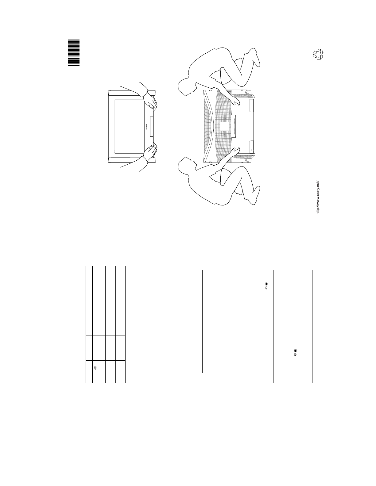
Lifting the TV Set
- 13 -
27
Specifications
TV System
I/DVB-T
Colour System
PAL
NTSC 3.58, 4.43 (only Video In)
MPEG-2 MP@ML
Channel Coverage
UHF: B21-B69
Picture Tube
KD-28DX51: FD Trinitron WIDE Approx. 71cm (28inches)
KD-32DX51: FD Trinitron WIDE Approx. 82cm (32inches)
Sound Output
Left/Right: 2x14W (music power), 2x7W (RMS)
Power Consumption
KD-28DX51: 80W
KD-32DX51: 88W
Standby Power
Consumption
0.6W
Dimensions (w x h x d)
KD-28DX51: Approx. 784 x 496 x 543 mm
KD-32DX51: Approx. 895 x 575 x 588 mm
Weight
KD-28DX51: Approx. 44kg
KD-32DX51: Approx. 61kg
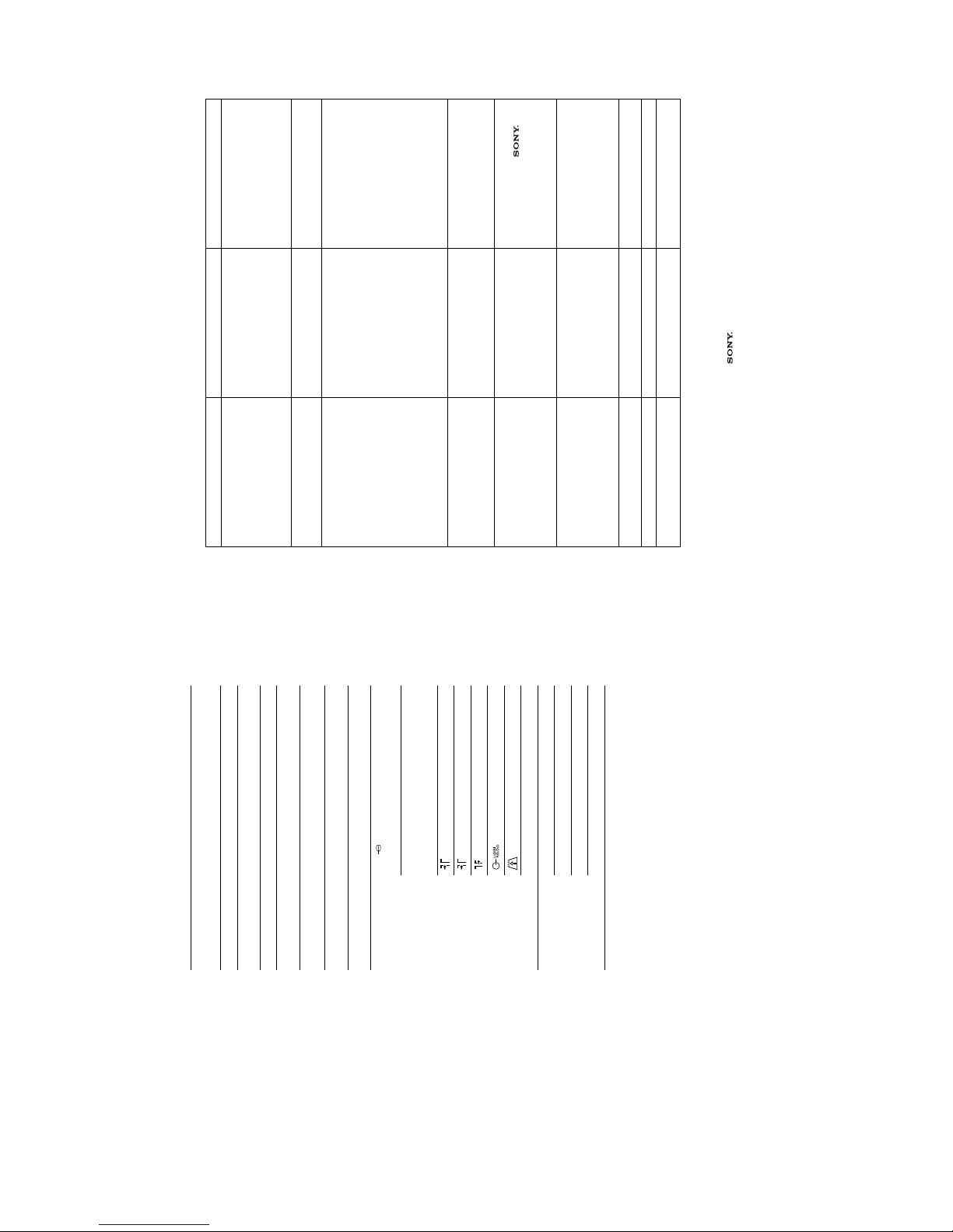
Rear Terminals
i1/ 21-pin Euro connector (CENELEC
standard) including audio/video input,
RGB input, TV audio/video output.
i2/r 21-pin Euro connector (CENELEC
standard) including audio/video input,
S-VIDEO input, selectable audio/video
output.
RF In (DIGITAL)
RF In (ANALOGUE)
RF Out
Audio output - phono jacks.
PCMCIA (for future use only).
MODEM MODEM jack (for future use only).
Front Terminals
i Headphone jack - minijack stereo.
r3 S-V ideo input - 4 pin DIN
t3 Video input - phono jack.
o3 Audio input - phono jack.
Supplied Accessories
RM-949 remote control (1)
IEC designated size AA (R06) battery (2)
RF Lead.
Design and specification are subject to change without notice.
Additional Information
28
Troubleshooting
Here are some simple solutions to problems which may affect the picture and sound.
Problem Cause Solution
No picture, no sound. • Power off.
• TV in standby.
• Aerial disconnected.
• Plug in the TV.
• If the 1 indicator is lit, press the
TV I/1 button on the remote control.
•Press the ! button on the front of the
TV.
• Check aerial connection.
Poor or no picture (screen is dark), good
sound.
• Low picture settings. • Access the ‘Picture Adjustment’
menu and adjust the ‘Brightness’,
‘Colour’ and ‘Contrast’ settings.
No picture on any channel after digital
tuning.
• No digital transmissions in your area.
• Weak signal.
• Unsuitable aerial.
• Tune in all available analogue
channels. Refer to the section
‘Manual Programme Preset’. Contact
a local installer to find out when
digital transmissions begin in your
area.
• Ensure aerial is correctly aligned to
transmitter.
• Ensure aerial is plugged directly into
the TV (not through other
equipment).
• Upgrade to a higher gain aerial.
• Upgrade to a higher gain aerial.
Some channels are blank. • Channel not being transmitted.
• Channel used only for data (no
picture or sound).
• Contact the broadcaster for
transmission details
Standby indicator flashing. • Fault (irregular flashing).
• Digital programme set for ’Timer
Record’ (regular flash)
• Do not open the cabinet, refer to
qualified personnel.
• Contact your nearest
Service Centre.
• Refer to the EPG section of this
manual.
Good picture, no sound • Low or muted volume
• TV speakers turn ed ‘Off’.
• Press the 2 + button on the remote
control.
• If % is displayed, press the % button
on the remote control.
• Set TV speakers to ‘On’ in the Detail
Adjustment menu.
No colour on colour programmes. • Low colour level settings. • Access the ‘Picture Adjustment’
menu and adjust the ‘Colour’ setting.
Remote control does not work. • Batteries low. • Replace batteries.
Distorted picture when changing
programmes or selecting text.
• Connected equipment switched on. • Switch off external equipment (VCR,
DVD player etc.)
• If you continue to have these problems, have your TV serviced by qualified
personnel or contact the UK Digital HelpLine on 0870 600 1717.
• NEVER open the casing yourself.
Additional Information
- 14 -
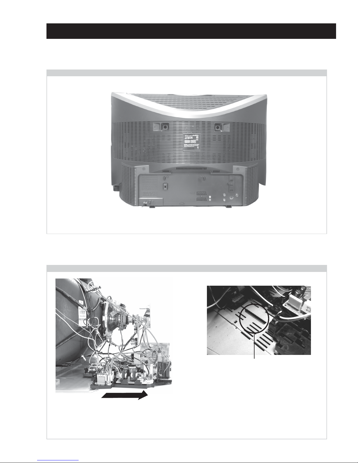
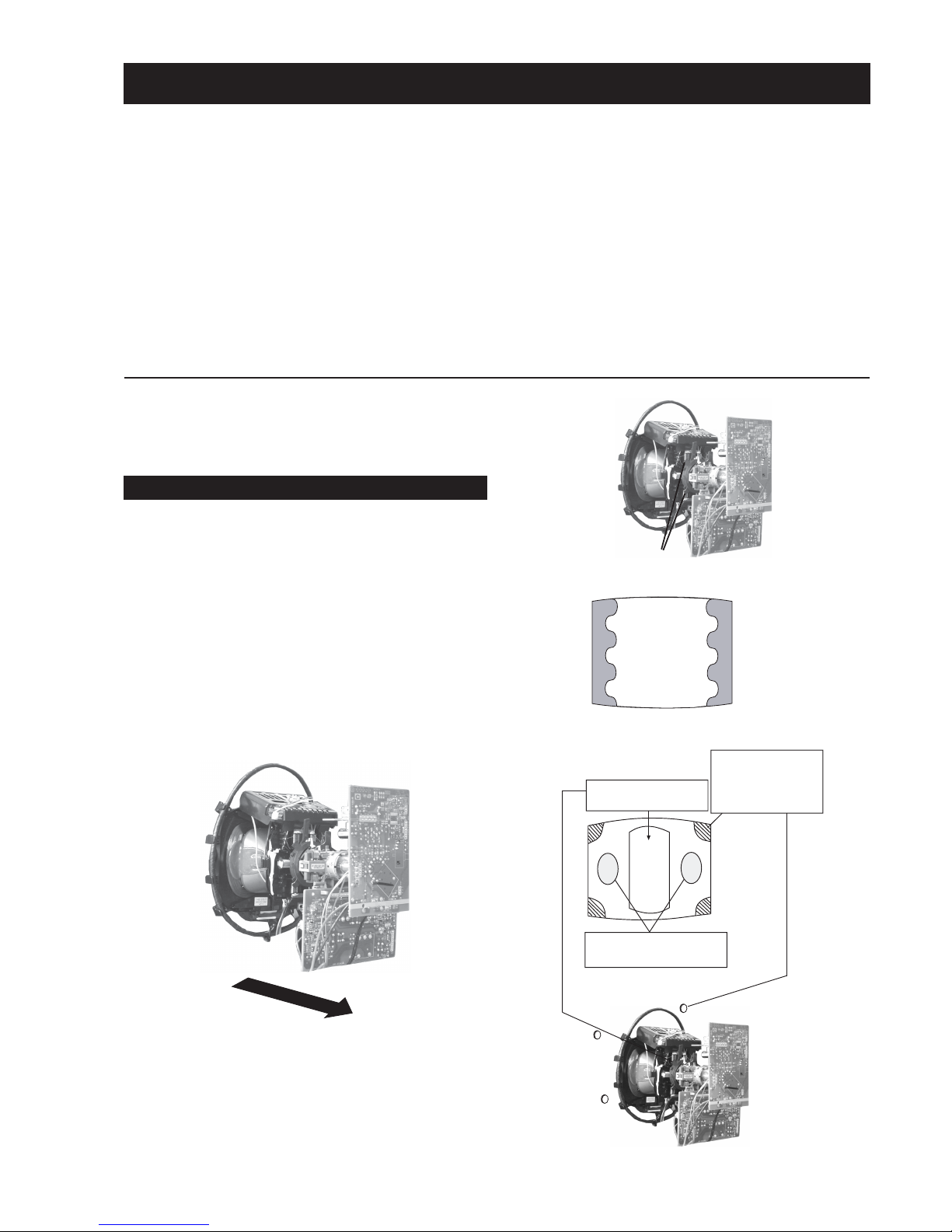
Remove the rear cover fixing screws indicated and withdraw the rear cover from the Beznet.
SECTION 2 DISASSEMBLY
To remove lift the main bracket rear slightly and slide the
chassis away from the beznet. Ensure that the interconnecting
leads are released from their purse locks to prevent damage
being caused.
When refitting the chassis ensure that the main
bracket is located in the beznet guide slots before
sliding the chassis forwards. Refit the
interconnecting leads in their respective purse locks.
2-2. Chassis Removal and Refitting
2-1. Rear Cover Removal
=>
=>
=>
=>
=>
<=
<=
=>
<=
<=
=>
=>
- 15 -
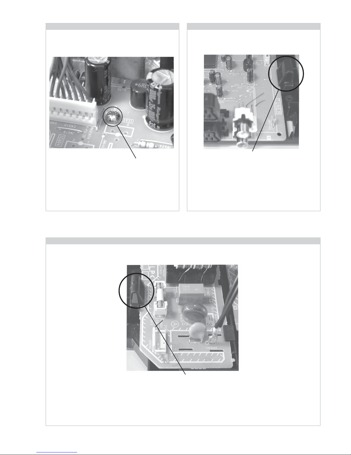
2-3. A Board Removal [ Step 1 ] 2-4. A Board Removal [ Step 2 ]
2-5. F3 Board Removal
Screw.
Release the 5 securing clips located around the side of the
chassis and slide the PWB clear of the bracket.
Remove the 3 screws securing the PWB to the main bracket.
1 can be seen in the photo above and the other 2 are either
side of the FBT assembly.
Clip.
Clip.
Release the 2 securing clips located along the side of the
chassis and slide the PWB clear of the bracket.
- 16 -
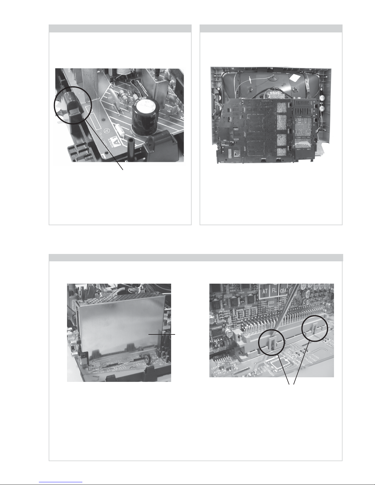
2-6. A1 Board Removal 2-7. Service Position
Position the chassis as indicated to access the solder side
of the PWB’s. To gain access to the A Board follow the
instructions on page 18. [Removal and Replacement of the
main bracket bottom plates ].
Remove the shield case by pulling vertically until it is clear of the N Board. Release the N board socket retaining clips, circled, by
gently prising them with a screwdriver and carefully lift the N Board vertically.
2-8. N Board Removal
Clips
Shield
case
Clip.
Release the 4 securing clips located around the side of the
chassis and slide the PWB clear of the bracket.
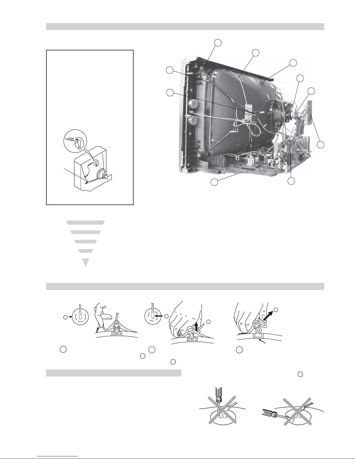
- 17 -
Anode button
a
* REMOVING PROCEDURES.
Turn up one side of the rubber cap in
the direction indicated by the arrow a
1
2 Using a thumb pull up the rubber cap
firmly in the direction indicated by the
arrow b
3 When one side of the rubber cap is
separated from the anode button, the
anode-cap can be removed by turning
up the rubber cap and pulling it up in
the direction of the arrow c
b
b
c
How to handle the Anode-Cap
1. To prevent damaging the surface of the anode-cap do not use
sharp materials.
2. Do not apply too great a pressure on the rubber, as this may cause
damage to the anode connector.
3. A metal fitting called a shatter hook terminal is fitted inside the
rubber cap.
4. Do not turn the rubber foot over excessively, this may cause
damage if the shatter hook sticks out.
Removal of the Anode-Cap
2-9. Picture Tube Removal
WARNING:
BEFORE REMOVING
THE ANODE CAP
High voltage remains in the CRT even
after the power is disconnected. To
avoid electric shock, discharge CRT
before attempting to remove the anode
cap. Short between anode and CRT
coated earth ground strap.
Coated Earth
Ground Strap
1. Discharge the anode of the CRT and remove the anode cap.
2. Unplug all interconnecting leads from the Deflection yoke, neck
assy, degaussing coils and CRT grounding strap.
3. Remove the C Board from the CRT.
4. Remove the chassis assembly.
5. Loosen the Neck assembly fixing screw and remove.
6. Loosen the Deflection yoke fixing screw and remove.
7. Place the set with the CRT face down on a cushion and remove
the Degaussing Coil holders.
8. Remove the Degaussing Coils.
9. Remove the CRT grounding strap and spring tensioners.
10. Unscrew the four CRT fixing screws [ located on each CRT
corner ] and remove the CRT.
[Take care not to handle the CRT by the neck.]
1
4
6
8
10
5
9
2
7
3
- 18 -
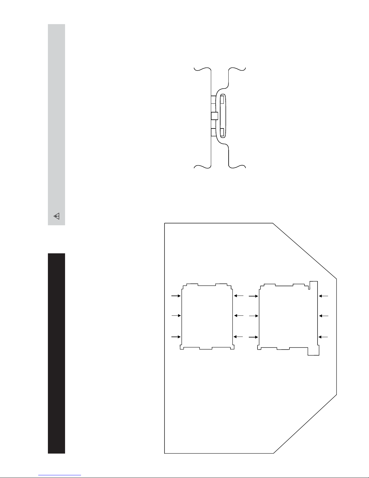
REMOVAL AND REPLACEMENT OF THE MAIN-BRACKET
BOTTOM PLATES.
(1) REMOVING THE PLATES
In the event of servicing being required to the solder side of the A Board printed wiring board, the
bottom plates fitted to the main chassis bracket require to be removed.
This is performed by cutting the gates with a sharp wire cutter at the locations indicated by the
arrows.
Note : There are 2 plates fitted to the main bracket.
Only remove the necessary plate to gain access to the printed wiring board.
(2) REFITTING THE PLATES
Because the plates differ in size it is important that the correct plates are refitted in their original
location.
Please note that the plates need to be rotated 180 degrees from their cut position to allow the tabs to
be fitted into their catch positions.
For safety reasons, on no account should the plates be re-
moved and not refitted after servicing.
Ta b
Catch
- 19 -
GREEN
BLUE
RED
ab
c
d
Purity control corrects
this area
Deflection yoke positioning
corrects these areas
Disk magnets or
rotatable disk
magnets correct
these areas (a-d)
Disk Magnets
Preparation:
1. In order to reduce the influence of geomagnetism on the
set’s picture tube, face it in an easterly or westerly direction.
2. Switch on the set’s power and degauss with the degausser.
1. Input an all white signal from the pattern generator. Set the
Contrast and Brightness to normal.
2. Set the pattern generator raster signal to Red.
3. Move the deflection yoke forward and adjust with the
purity control so that the Red is at the centre and the Blue
and Green take up equally sized areas on each side of the
screen. [See Fig.3-1 - 3-3].
4. Move the deflection yoke backwards and adjust so that the
entire screen becomes Red. [See Fig.3-1]
5. Switch the raster signal to Blue, then to Green and verify
the condition.
6. When the position of the deflection yoke has been
determined, fasten the deflection yoke with the screws.
7. If the beam does not land correctly in all the corners, use a
magnet to correct it. [See Fig.3-4]
• When complete readjustment is necessary or a new picture
tube is installed, carry out the following adjustments.
• Unless there are specific instructions to the contrary, carry
out these adjustments with the rated power supply.
• Unless there are specific instructions to the contrary, set the
controls and switches to the following settings :
Contrast .................... 80% [or remote control normal]
Brightness ................... 50%
Carry out the adjustments in the following order :
3-1. Beam Landing.
3-2. Convergence.
3-3. Focus.
3-4. White Balance.
Note : Test equipment required.
1. Color bar/pattern generator.
2. Degausser.
3. Oscilloscope.
4. Digital multimeter.
Caution :
High voltages are present on the Deflection yoke terminals
- take care when handling the Deflection yoke whilst carrying
out adjustments.
Fig.3-4
Fig. 3-1.
Fig. 3-3.
Fig. 3-2.
Purity
SECTION 3 SET-UP ADJUSTMENTS
3-1. Beam Landing
- 20 -
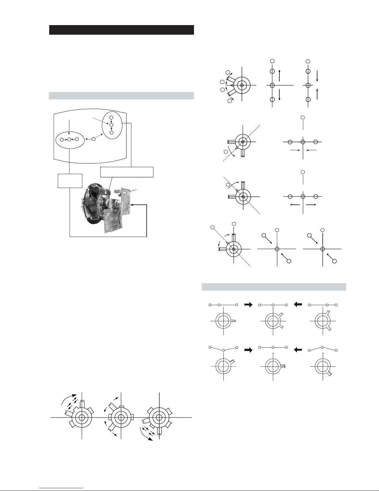
4. If the V.STAT magnet is moved in the direction of the (a)
and (b) arrows, the Red, Green and Blue points move as
indicated below.
1. [Moving horizontally], adjust the H.STAT control so that
the Red, Green and Blue points are on top of each other at
the centre of the screen.
2. [Moving vertically], adjust the V.STAT magnet so that the
Red, Green and Blue points are on top of each other at the
centre of the screen.
3. If the H.STAT variable resistor is unable to bring the Red,
Green and Blue points together at the centre of the screen,
adjust the horizontal convergence with the H.STAT variable
resistor and the V.STAT magnet in the manner indicated
below.
[In this case, the H.STAT variable resistor and the V.STAT
magnet influence each other].
The movement of the magnets interact with each other and so
the respective dot position should be monitored while carrying
out this adjustment.
Use the H.STAT VR to adjust the Red, Green and Blue dots so
that they coincide at the centre of the screen
(by moving the dots in the horizontal direction).
GBR
GBR
GBR
G
B
R
GBR
G
B
R
3-2. Convergence
Preparation:
• Before starting this adjustment, adjust the focus, horizontal
size and vertical size.
• Minimize the Brightness setting.
• Input a dot pattern from the pattern generator.
Horizontal and Vertical Static Convergence
Operation of the BMC (Hexapole) magnet.
Fig.3-5
• Tilt the V.STAT magnet and adjust the static convergence by
opening or closing the V.STAT magnet.
B
G
R
B
G
R
a
a
b
b
a
b
B
G
R
a
a
B
G
R
b
b
B
G
R
a
b
R
G
B
b
a
Center dot
R
G
B
R
G
B
C Board
RV702 (H STAT)
H STAT Convergence
(on mount side)
H STAT
convergence
control
V.STAT Vertical Static Magnet
- 21 -
+++
TLV VR 28"
Deflection Yoke
+
++
TLV VR 32"
Deflection Yoke
+
+
+
YCH VR 28"
Deflection Yoke
+
+
+
YCH VR 32"
Deflection Yoke
Tilt Direction
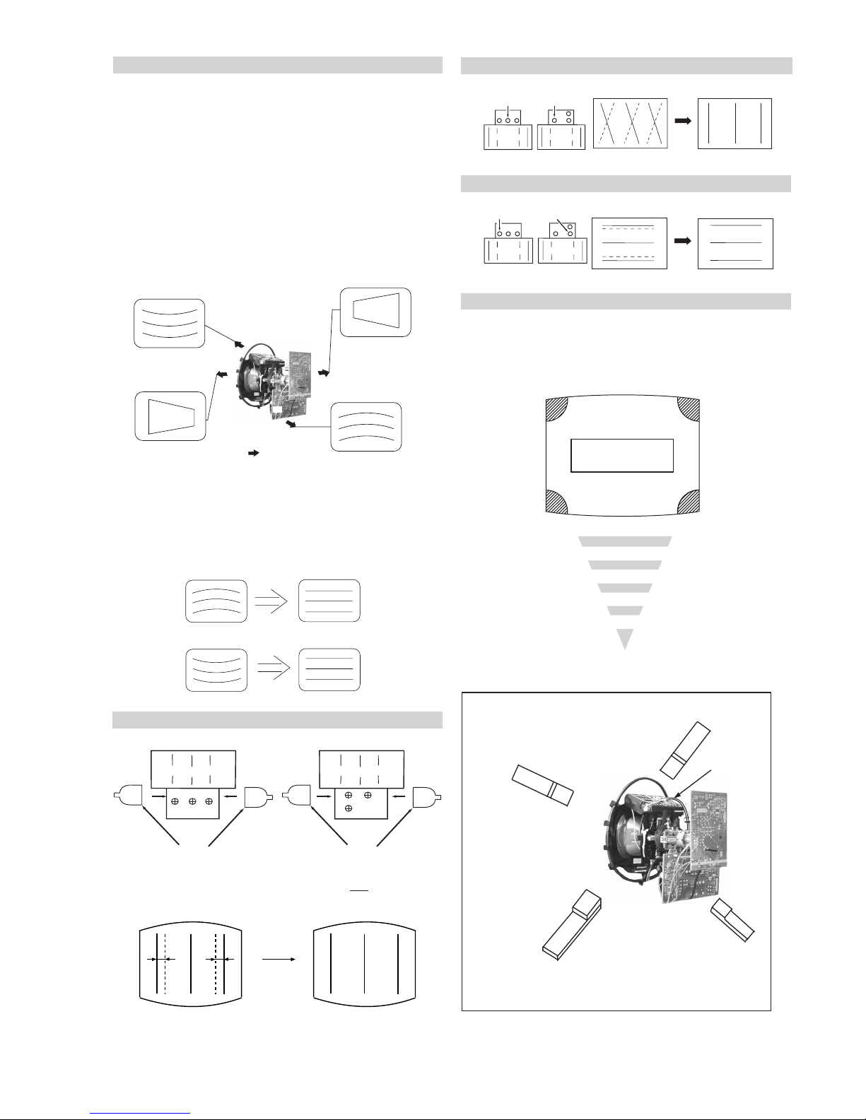
If you are unable to adjust the corner convergence properly,
this can be corrected with the use of permalloy magnets.
HTIL correction can be performed by adding
one TLH
correction assembly to the Deflection yoke.
HTIL Adjustment
YCH Adjustment
TLV Adjustment
Geometry Adjustment.
Preparation:
Before starting this adjustment, adjust the horizontal and
vertical static convergence.
1. Remove the deflection yoke spacer.
2. Tilt the deflection yoke as indicated in the figure below and
optimise the geometry.
Tilting the DY Up and Down a small amount will balance
the upper and lower pin adjustment.
3. Re-install the deflection yoke spacers. Ensure 4 DY spacers are
reinserted
Screen Corner Convergence
a
b
d
Permalloy Assy
c
Install the permalloy assembly
for the area that needs correcting.
X-4387-214-1
Convergence adjustment with permalloy
APH circuit
harness
Deflection Yoke
TLH Piece
H-Trap YCH TLV
Deflection Yoke
TLH Piece
H-Trap
YCH
TLV
4. The H-Trap and T-B Pin may not achieve a good level due
to a small tilt allowance on the square DY. Keep the DY in
a straight position and adjust H-Trap pot (See diagram for
HTIL Adjustment) and Y-Mg for T-B Pin, as below.
28” 32”
• APH Convergence parameter is electrically controlled. For this
reason a TLH piece may not be required.
(APH = Red vertical lines on the edge of the screen).
a-d: screen-corner
convergence defect
a
b
c
d
 Loading...