

Sony TRINITRON CPD-G500 Service Manual
CPD-G500
CRT 0.24 mm aperture grille pitch
21 inches measured diagonally
90-degree deflection
FD Trinitron
Viewable image size Approx. 403.8 × 302.2 mm (w/h)
(16 × 12 inches)
19.8" viewing image
Resolution
Maximum Horizontal: 2048 dots
Vertical: 1536 lines
Recommended Horizontal: 1600 dots
Vertical: 1200 lines
Standard image area Approx. 388 × 291 mm (w/h)
(15
3
/8 × 11 1/2 inches)
or
Approx. 364 × 291 mm (w/h)
(14
3
/8 × 11 1/2 inches)
Deflection frequency* Horizontal: 30 to 121 kHz
Vertical: 48 to 160 Hz
AC input voltage/current 100 to 240 V, 50 – 60 Hz, 2.0 – 1.0 A
Power consumption Approx. 145 W
Dimensions
Approx. 497 × 480 × 478 mm (w/h/d)
(19
5
/8 × 19 × 18 7/8 inches)
Mass Approx. 32 kg (70 lb 9 oz)
Plug and Play DDC1/2B/2Bi, GTF**
* Recommended horizontal and vertical timing condition
• Horizontal sync width duty should be more than 4.8% of total
horizontal time or 0.8 µs, whichever is larger.
• Horizontal blanking width should be more than 2.3 µsec.
• Vertical blanking width should be more than 450 µsec.
** If the input signal is Generalized Timing Formula (GTF)
compliant, the GTF feature of the monitor will automatically
provide an optimal image for the screen.
Design and specifications are subject to change without notice.
SERVICE MANUAL
SPECIFICATIONS
US Model
Canadian Model
AEP Model
Chassis No. SCC-L22C-A
S.Hemisphere Model
Chassis No. SCC-L22G-A
Equator Model
Chassis No. SCC-L22F-A
G1
CHASSIS
TRINITRON
®
COLOR COMPUTER DISPLAY
CPD-G500
SAFETY CHECK-OUT
After correcting the original service problem, perform the following safety checks before releasing the set to the customer:
1. Check the area of your repair for unsoldered or poorly-soldered connections. Check the entire board surface for solder
splashes and bridges.
2. Check the interboard wiring to ensure that no wires are
“pinched” or contact high-wattage resistors.
3. Check that all control knobs, shields, covers, ground straps,
and mounting hardware have been replaced. Be absolutely
certain that you have replaced all the insulators.
4. Look for unauthorized replacement parts, particularly transistors, that were installed during a previous repair. Point
them out to the customer and recommend their replacement.
5. Look for parts which, though functioning, show obvious
signs of deterioration. Point them out to the customer and
recommend their replacement.
6. Check the line cords for cracks and abrasion. Recommend
the replacement of any such line cord to the customer.
7. Check the B+ and HV to see if they are specified values.
Make sure your instruments are accurate; be suspicious of
your HV meter if sets always have low HV.
8. Check the antenna terminals, metal trim, “metallized”
knobs, screws, and all other exposed metal parts for AC
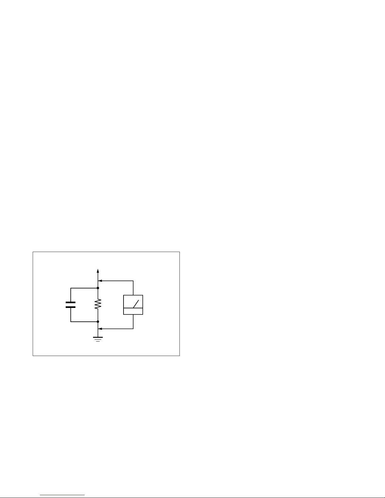
Leakage. Check leakage as described below.
To Exposed Metal
Parts on Set
0.15 µF
1.5 k
Ω
AC
Voltmeter
(0.75 V)
LEAKAGE TEST
The AC leakage from any exposed metal part to earth ground
and from all exposed metal parts to any exposed metal part having a return to chassis, must not exceed 0.5 mA (500 microamperes).
Leakage current can be measured by any one of three methods.
1. A commercial leakage tester, such as the Simpson 229 or
RCA WT-540A. Follow the manufacturers’ instructions to
use these instruments.
2. A battery-operated AC milliammeter. The Data Precision
245 digital multimeter is suitable for this job.
3. Measuring the voltage drop across a resistor by means of a
VOM or battery-operated AC voltmeter. The “limit” indication is 0.75 V, so analog meters must have an accurate lowvoltage scale. The Simpson 250 and Sanwa SH-63Trd are
examples of a passive VOMs that are suitable. Nearly all
battery operated digital multimeters that have a 2 V AC
range are suitable. (See Fig. A)
WARNING!!
NEVER TURN ON THE POWER IN A CONDITION IN
WHICH THE DEGAUSS COIL HAS BEEN REMOVED.
SAFETY-RELATED COMPONENT WARNING!!
COMPONENTS IDENTIFIED BY SHADING AND MARK
¡ ON THE SCHEMATIC DIAGRAMS, EXPLODED
VIEWS AND IN THE PARTS LIST ARE CRITICAL FOR
SAFE OPERATION. REPLACE THESE COMPONENTS
WITH SONY PARTS WHOSE PART NUMBERS APPEAR AS SHOWN IN THIS MANUAL OR IN SUPPLEMENTS PUBLISHED BY SONY. CIRCUIT ADJUSTMENTS THAT ARE CRITICAL FOR SAFE OPERATION
ARE IDENTIFIED IN THIS MANUAL. FOLLOW THESE
PROCEDURES WHENEVER CRITICAL COMPONENTS
ARE REPLACED OR IMPROPER OPERATION IS SUSPECTED.
Earth Ground
Fig. A. Using an AC voltmeter to check AC leakage.
AVERTISSEMENT!!
NE JAMAIS METTRE SOUS TENSION QUAND LA
BOBINE DE DEMAGNETISATION EST ENLEVÉE.
ATTENTION AUX COMPOSANTS RELATIFS À LA
SÉCURITÉ!!
LES COMPOSANTS IDENTIFIÉS PAR UNE TRAME ET
UNE MARQUE
¡ SONT CRITIQUES POUR LA SÉCURITÉ.
NE LES REMPLACER QUE PAR UNE PIÈCE PORTANT LE
NUMÉRO SPECIFIÉ. LES RÉGLAGES DE CIRCUIT DONT
L’IMPORTANCE EST CRITIQUE POUR LA SÉCURITÉ DU
FONCTIONNEMENT SONT IDENTIFIÉS DANS LE
PRÉSENT MANUEL. SUIVRE CES PROCÉDURES LORS
DE CHAQUE REMPLACEMENT DE COMPOSANTS CRITIQUES, OU LORSQU’UN MAUVAIS FONCTIONNEMENT
EST SUSPECTÉ.
– 2 –
Power saving function
This monitor meets the power-saving guidelines set by VESA,
E
NERGY STAR, and NUTEK. If the monitor is connected to a
computer or video graphics board that is DPMS (Display Power
Management Signaling) compliant, the monitor will automatically
reduce power consumption in three stages as shown below
.
CPD-G500
Power mode Power consumption 1 (power)
indicator
normal
≤ 145 W green
operation
1 standby ≤ 100 W green and orange
alternate
2 suspend
(sleep)*
3 active off**
≤ 15 W green and orange
alternate
Approx. 1 W orange
(deep sleep)*
power off 0 W off
* “Sleep” and “deep sleep” are power saving modes defined by the
Environmental Protection Agency.
** When your computer enters a power saving mode, the input signal is
cut and NO INPUT SIGNAL appears on the screen. After a few
seconds, the monitor enters a power saving mode.
DIAGNOSIS
This monitor is equipped with a self-diagnosis function. If there is
a problem with your monitor or computer(s), the screen will go
blank and the 1 (power) indicator will either light up green or
flash orange. If the 1 (power) indicator is lit in orange, the
computer is in power saving mode. Try pressing any key on the
keyboard.
If all four color bars appear (white, red, green, blue), the monitor
is working properly. Reconnect the video input cables and check
the condition of your computer(s).
If the color bars do not appear, there is a potential monitor failure.
Inform your authorized Sony dealer of the monitor’s condition.
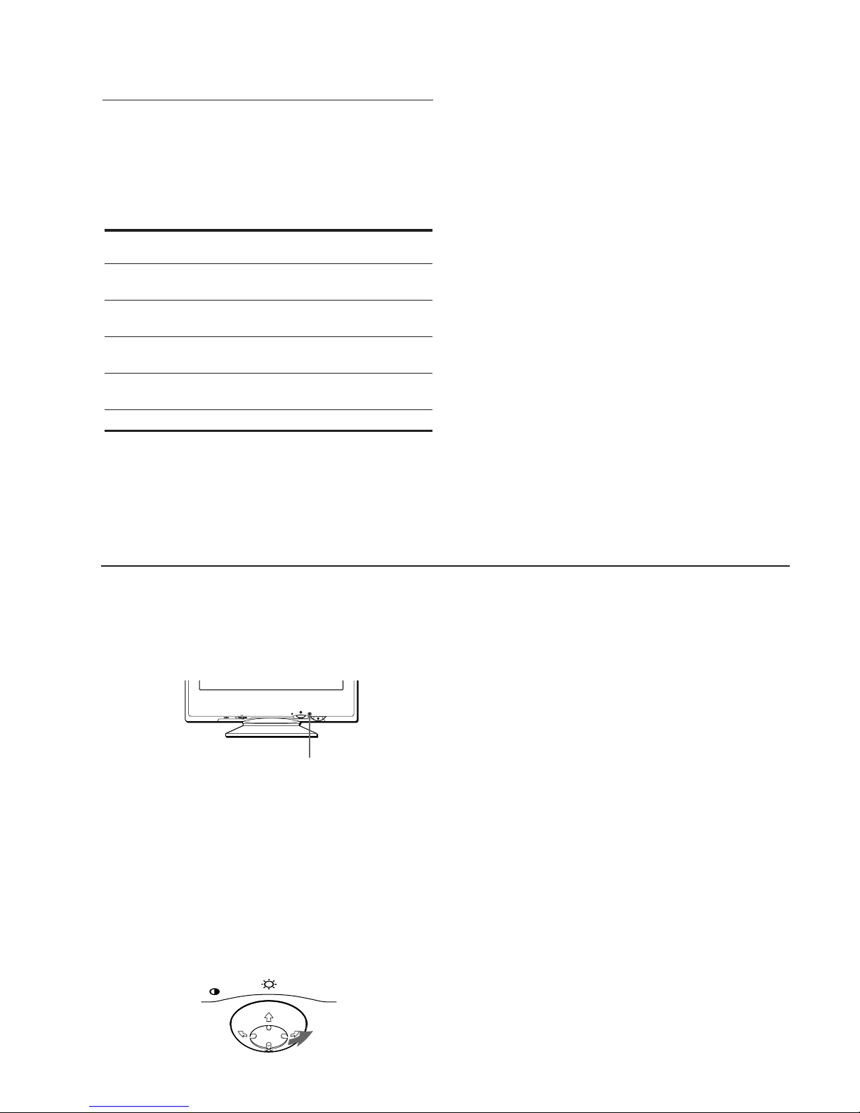
RESET INPUTHD15 BNC
1 (power) indicator
If the 1 (power) indicator is green
1
Remove any plugs from the video input 1 and 2
connectors, or turn off the connected computer(s).
2
Press the 1 (power) button twice to turn the monitor
off and then on.
3
Move the control button , for 2 seconds before the
monitor enters power saving mode.
MENU
MENU
If the 1 (power) indicator is flashing orange
Press the 1 (power) button twice to turn the monitor off
and then on.
If the 1 (power) indicator lights up green, the monitor is working
properly.
If the 1 (power) indicator is still flashing, there is a potential
monitor failure. Count the number of seconds between orange
flashes of the 1 (power) indicator and inform your authorized
Sony dealer of the monitor’s condition. Be sure to note the model
name and serial number of your monitor. Also note the make and
model of your computer and video board.
– 3 –
CPD-G500
TIMING SPECIFICATION
MODE AT PRODUCTION MODE 1 MODE 2 MODE 3 MODE 4
RESOLUTION 1600 X 1200 1920 X 1440 1800 X 1440 1800 X 1350
CLOCK 229.500 MHz 297.000 MHz 299.436 MHz 300.000 MHz
— HORIZONTAL —
H-FREQ 106.250 kHz 112.500 kHz 120.740 kHz 120.968 kHz
H. TOTAL 9.412 8.889 8.282 8.267
H. BLK 2.440 2.424 2.271 2.267
H. FP 0.279 0.485 0.668 0.480
H. SYNC 0.837 0.754 0.481 0.667
H. BP 1.325 1.185 1.122 1.120
H. ACTIV 6.972 6.465 6.011 6.000
— VERTICAL —
V. FREQ(HZ) 85.000 Hz 75.000 Hz 80.120 Hz 85.009 Hz
V. TOTAL 1250 1500 1507 1423
V. BLK 50 60 67 73
V. FP 1111
V. SYNC 3333
V. BP 46 56 63 69
V. ACTIV 1200 1440 1440 1350
— SYNC —
INT(G) NO NO NO NO
EXT(H/V)/POLARITY YES P/P YES P/P YES P/P YES P/P
EXT(CS) /POLARITY NO NO NO NO
INT/NON INT NON INT NON INT NON INT NON INT
usec usec usec usec
lines lines lines lines
99.07.02 VER.
– 4 –

TABLE OF CONTENTS
Section Title Page
1. GENERAL ................................................................. 1-1
2. DISASSEMBLY
2-1. Cabinet Removal ............................................... 2-1
2-2. D Board Removal .............................................. 2-1
2-3. G Board Removal .............................................. 2-2
2-4. A Board, I/O Terminal Board Assembly
Removal ............................................................. 2-2
2-5. N Board Removal .............................................. 2-3
2-6. Service Position .................................................. 2-3
2-7. Bezel Assembly, H1 Board Removal ................ 2-4
2-8. Picture Tube Removal ....................................... 2-4
2-9. J Board Removal ............................................... 2-5
2-10. Harness Location ............................................... 2-6
CPD-G500
3. SAFETY RELATED ADJUSTMENT............. 3-1
4. ADJUSTMENTS ..................................................... 4-1
5. DIAGRAMS
5-1. Block Diagrams .................................................. 5-1
5-2. Frame Shcematic Diagram ................................. 5-7
5-3. Circuit Boards Location ..................................... 5-9
5-4. Schematic Diagrams and Printed Wiring
Boards ................................................................. 5-9
(1) Schematic Diagram of A Board ........................ 5-11
(2) Schematic Diagrams of H1, J Boards ............... 5-17
(3) Schematic Diagram of D Board ........................ 5-19
(4) Schematic Diagrams of N (a, b, c) Board .. 5-23
(5) Schematic Diagram of G Board ........................ 5-31
5-5. Semiconductors ................................................. 5-35
6. EXPLODED VIEWS
6-1. Chassis ............................................................... 6-1
6-2. Picture Tube ...................................................... 6-2
6-3. Packing Materials ............................................... 6-3
7. ELECTRICAL PARTS LIST ............................ 7-1
Note: Hand degauss must be used on stand-by or power-off condition.
This model has an automatic earth magnetism correction function by using an earth
magnetism sensor and a LCC coil. When using a hand degauss while monitor (LCC
coil) is being operated, it sometimes gets magnetized, and the system may not work
properly as a result.
– 5 –
SECTION 1
GENERAL
The operating instructions mentioned here are partial abstracts
from the Operating Instruction Manual. The page numbers of
the Operating Instruction Manual remain as in the manual.
1-1
4
Precautions
Warning on power connections
• Use the supplied power cord. If you use a different power cord,
be sure that it is compatible with your local power supply.
For the customers in the U.S.A.
If you do not use the appropriate cord, this monitor will not
conform to mandatory FCC standards.
• Before disconnecting the power cord, wait at least 30 seconds
after turning off the power to allow the static electricity on the
screen’s surface to discharge.
• After the power is turned on, the screen is demagnetized
(degaussed) for about 2 seconds. This generates a strong
magnetic field around the screen which may affect data stored
on magnetic tapes and disks placed near the monitor. Be sure to
keep magnetic recording equipment, tapes, and disks away
from the monitor.
Installation
Do not install the monitor in the following places:
• on surfaces (rugs, blankets, etc.) or near materials (curtains,
draperies, etc.) that may block the ventilation holes
• near heat sources such as radiators or air ducts, or in a place
subject to direct sunlight
• in a place subject to severe temperature changes
• in a place subject to mechanical vibration or shock
• on an unstable surface
• near equipment which generates magnetism, such as a
transformer or high voltage power lines
• near or on an electrically charged metal surface
Maintenance
• Clean the screen with a soft cloth. If you use a glass cleaning
liquid, do not use any type of cleaner containing an anti-static
solution or similar additive as this may scratch the screen’s
coating.
• Do not rub, touch, or tap the surface of the screen with sharp or
abrasive items such as a ballpoint pen or screwdriver. This type
of contact may result in a scratched picture tube.
• Clean the cabinet, panel and controls with a soft cloth lightly
moistened with a mild detergent solution. Do not use any type
of abrasive pad, scouring powder or solvent, such as alcohol or
benzene.
Transportation
When you transport this monitor for repair or shipment, use the
original carton and packing materials.
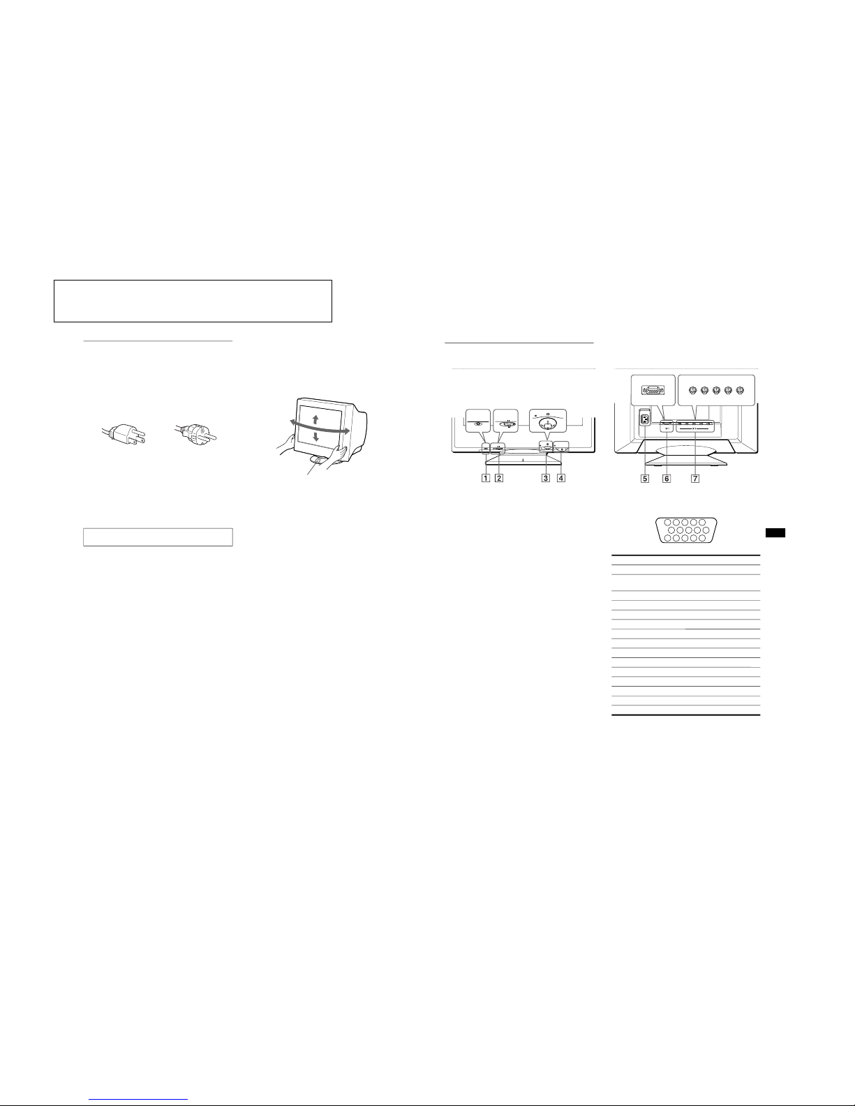
Use of the tilt-swivel
This monitor can be adjusted within the angles shown below. To
find the center of the monitor’s turning radius, align the center of
the monitor’s screen with the centering dots on the stand.
Hold the monitor at the bottom with both hands when you turn it
horizontally or vertically. Be careful not to pinch your fingers at
the back of the monitor when you tilt the monitor up vertically.
The equipment should be installed near an easily accessible
outlet.
Example of plug types
for 100 to 120 V AC
for 200 to 240 V AC
90˚
5˚
90˚
15˚
Centering dots
5
US
Identifying parts and controls
See the pages in parentheses for further details.
1 RESET (reset) button (page 16)
This button resets the adjustments to the factory settings.
2 INPUT (input) switch (page 8)
This switch selects the HD15 or BNC video input signal.
3 Control button (page 10)
The control button is used to display the menu and make
adjustments to the monitor, including brightness and contrast
adjustments.
4 1 (power) switch and indicator (pages 7, 16, 20)
This button turns the monitor on and off. The power indicator
lights up in green when the monitor is turned on, and either
flashes in green and orange, or lights up in orange when the
monitor is in power saving mode.
5 AC IN connector (page 7)
This connector provides AC power to the monitor.
6 Video input 1 connector (HD15) (y1) (page 6)
This connector inputs RGB video signals (0.700 Vp-p,
positive) and sync signals.
* DDC (Display Data Channel) is a standard of VESA.
7 Video input 2 connector (BNC) (y2) (page 6)
This connector inputs RGB video signals (0.700 Vp-p,
positive) and sync signals.
MENU
RESET
INPUT
HD15BNC
MENU
RESET
INPUT
HD15 BNC
R G B HD VD
(HD15) (BNC)
AC IN
RearFront
rear side
forward side
forward side
rear side
Pin No. Signal
1 Red
2 Green
(Sync on Green)
3 Blue
4 ID (Ground)
5 DDC Ground*
6 Red Ground
7 Green Ground
8 Blue Ground
9 DDC + 5V*
10 Ground
11 ID (Ground)
12 Bi-Directional Data (SDA)*
13 H. Sync
14 V. Sync
15 Data Clock (SCL)*
5
4 3 2
1
678910
111213
1415
1-2
6
Setup
Before using your monitor, check that the following accessories
are included in your carton:
• Power cord (1)
• HD15 video signal cable (1)
• Macintosh adapter (1)
• Windows Monitor Information Disk (1)
• Warranty card (1)
• Notes on cleaning the screen’s surface (1)
• This instruction manual (1)
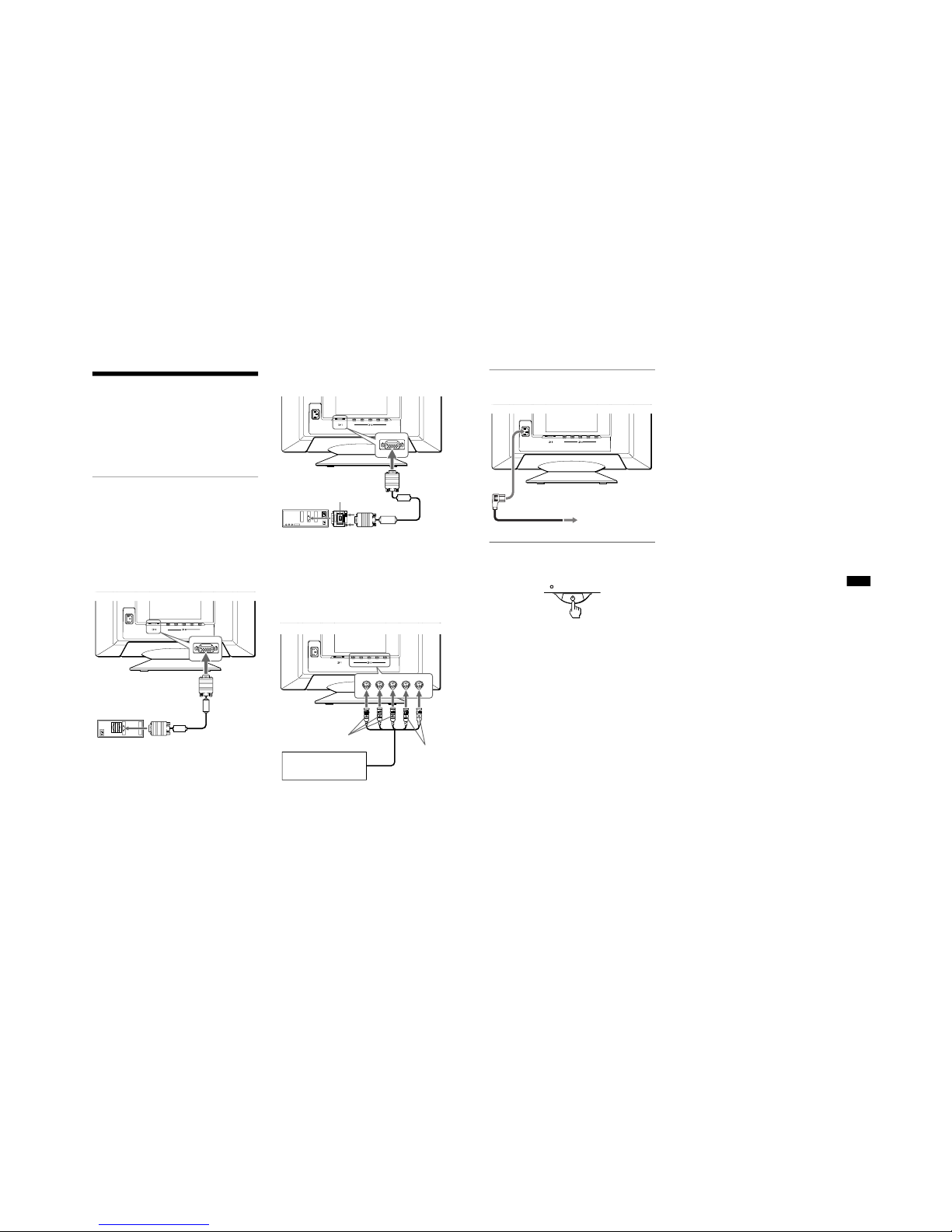
Step 1:Connect your monitor to
your computer
Turn off the monitor and computer before connecting.
Notes
• Do not touch the pins of the video signal cable connector as this might
bend the pins.
• When connecting the video signal cable, check the alignment of the
HD15 connector. Do not force the connector in the wrong way or the
pins might bend.
x Connecting to an IBM PC/AT or compatible
computer
x Connecting to a Macintosh or compatible
computer
* Connect the supplied Macintosh adapter to the computer before
connecting the cable. This adapter is compatible with Macintosh LC,
Performa, Quadra, Power Macintosh and Power Macintosh G3 series
computers (sold before January, 1999). If you are connecting to a
Power Macintosh G3 series that sold after January 1999, you will need
a different adapter (not supplied). Macintosh II series and some older
versions of PowerBook models may need an adapter with micro
switches (not supplied).
x Connecting to the five BNC connectors
* Connect the cables from left to right in the following order: Red-Green-
Blue-HD-VD.
Note
Plug & Play (DDC) does not apply to the five BNC connectors. If you
want to use Plug & Play, connect your computer to the HD15 connector
using the supplied video signal cable.
R G B HD VD
(HD15) (BNC)
AC IN
HD15 video signal
cable (supplied)
to video output
IBM PC/AT or compatible
computer
to HD15
R G B HD VD
(HD15) (BNC)
AC IN
to HD15
Macintosh adapter (supplied)*
Macintosh or
compatible computer
to video
output
HD15 video signal
cable (supplied)
R G B HD VD
(HD15) (BNC)
AC IN
to VIDEO IN R/G/B
to SYNC IN
HD/VD
Refer to the preceding
examples to connect to your
computer.
video signal cable
(SMF-400, not supplied)*
7
US
Step 2:Connect the power cord
With the monitor and computer switched off, first connect the
power cord to the monitor, then connect it to a power outlet.
Step 3:Turn on the monitor and
computer
First turn on the monitor, then turn on the computer.
The installation of your monitor is complete.
If necessary, use the monitor’s controls to adjust the picture.
If no picture appears on your screen
• Check that the monitor is correctly connected to the computer.
• If NO INPUT SIGNAL appears on the screen, try changing the
input signal (page 8), and confirm that your computer’s graphic
board is completely seated in the correct bus slot.
• If you are replacing an old monitor with this model and OUT
OF SCAN RANGE appears on the screen, reconnect the old
monitor. Then adjust the computer’s graphic board so that the
horizontal frequency is between 30 – 121 kHz, and the vertical
frequency is between 48 – 160 Hz.
For more information about the on-screen messages, see “Trouble
symptoms and remedies” on page 18.
For customers using Windows 95/98
To maximize the potential of your monitor, install the new model
information file from the supplied Windows Monitor Information Disk
onto your PC.
This monitor complies with the “VESA DDC” Plug & Play standard. If
your PC/graphics board complies with DDC, select “Plug & Play Monitor
(VESA DDC)” or this monitor’s model name as the monitor type in the
“Control Panel” of Windows 95/98. If your PC/graphics board has
difficulty communicating with this monitor, load the Windows Monitor
Information Disk and select this monitor’s model name as the monitor
type.
For customers using Windows NT4.0
Monitor setup in Windows NT4.0 is different from Windows 95/98 and
does not involve the selection of monitor type. Refer to the Windows
NT4.0 instruction manual for further details on adjusting the resolution,
refresh rate, and number of colors.
Adjusting the monitor’s resolution and color number
Adjust the monitor’s resolution and color number by referring to your
computer’s instruction manual. The color number may vary according to
your computer or video board. The color palette setting and the actual
number of colors are as follows:
• High Color (16 bit) t 65,536 colors
• True Color (24 bit) t about 16.77 million colors
In true color mode (24 bit), speed may be slower.
R G B HD VD
(HD15) (BNC)
AC IN
to AC IN
to a power outlet
power cord (supplied)
1-3
8
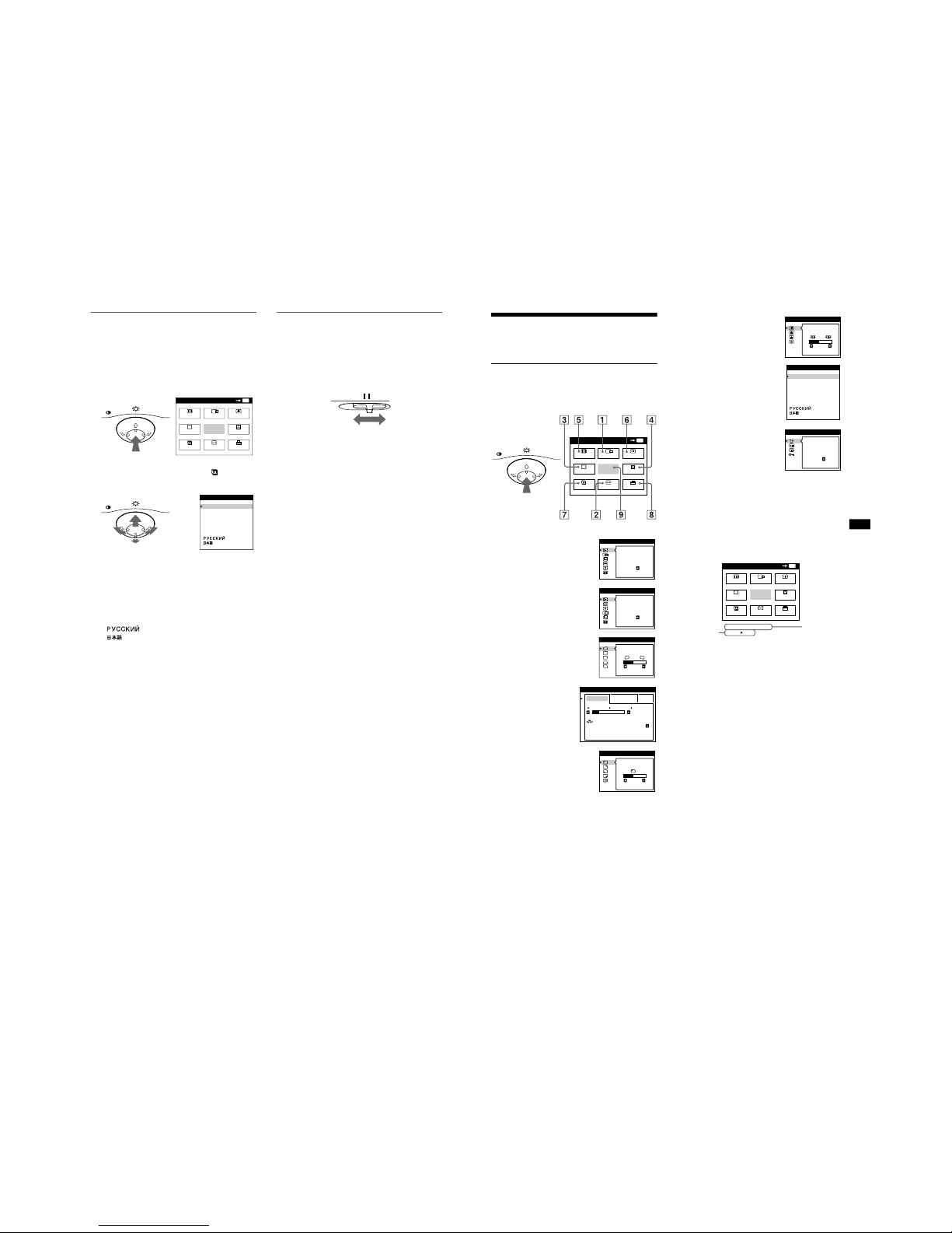
Selecting the on-screen menu
language (LANG)
English, French, German, Spanish, Italian, Dutch, Swedish,
Russian and Japanese versions of the on-screen menus are
available. The default setting is English.
1
Press the center of the control button.
See page 10 for more information on using the control button.
2
Move the control button to highlight LANG and
press the center of the control button again.
3
Move the control button m/M to select a language.
• ENGLISH
• FRANÇAIS: French
• DEUTSCH: German
• ESPAÑOL: Spanish
• ITALIANO: Italian
• NEDERLANDS: Dutch
• SVENSKA: Swedish
• : Russian
• : Japanese
To close the menu
Press the center of the control button once to return to the main MENU,
and twice to return to normal viewing. If no buttons are pressed, the menu
closes automatically after about 30 seconds.
To reset to English
Press the RESET button while the LANGUAGE menu is displayed on the
screen.
Selecting the input signal
You can connect two computers to this monitor using the HD15
and BNC connectors. To select one of the two computers, use the
INPUT switch.
Move the INPUT switch.
The selected connector appears on the screen for 3 seconds.
“HD15” or “BNC” appears on the screen.
Note
If no signal is input to the selected connector, NO INPUT SIGNAL
appears on the screen. After a few seconds, the monitor enters the power
saving mode. If this happens, switch to the other connector.
MENU
MENU
MENU
EXIT
CENTER
SIZE
GEOM
SCREEN
COLOR
LANG
CONV
OPTION
OK
MENU
ENGLI SH
FRANÇAI S
DEUTSCH
ESPAÑOL
ITALIANO
NEDERLANDS
SVENSKA
LANGUA GE
INPUT
HD15 BNC
9
US
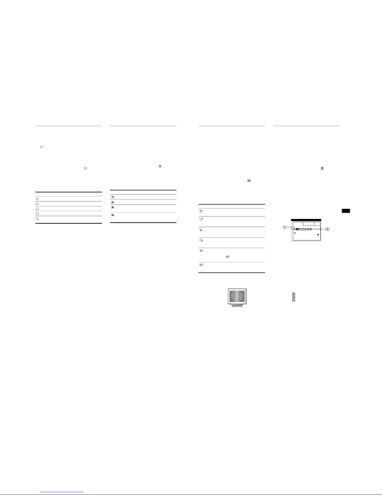
Customizing Your Monitor
You can make numerous adjustments to your monitor using the
on-screen menu.
Navigating the menu
Press the center of the control button to display the main MENU
on your screen. See page 10 for more information on using the
control button.
Use the control button to select one of the following menus.
x Displaying the current input signal
The horizontal and vertical frequencies of the current input signal
are displayed in the main MENU. If the signal matches one of this
monitor’s factory preset modes, the resolution is also displayed.
1 CENTER (page 11)
Selects the CENTER menu
to adjust the picture’s
centering, size or zoom.
2 SIZE (page 11)
Selects the SIZE menu to
adjust the picture’s size,
centering or zoom.
3 GEOM (page 12)
Select the GEOM menu to adjust the
picture’s rotation and shape.
4 COLOR (page 13)
Select the COLOR menu to
adjust the picture’s color
temperature. You can use
this to match the monitor’s
colors to a printed picture’s
colors.
5 SCREEN (page 13)
Select the SCREEN menu to adjust
the picture’s quality. You can adjust
the landing and moire cancellation
effect.
MENU
MENU
EXIT
CENTER
SIZE
GEOM
SCREEN
COLOR
LANG
CONV
OPTION
OK
MENU
AUTO
ON
SI ZE/ CENTER
AUTO
ON
SI ZE/ CENTER
26
GEOMETRY
EASY EXPERT s BGR
5000K 6500K 930 K0
50 K00
IMAGE
RESTORATI ON ON
COLOR
LANDING
26
SCREEN
6 CONV (page 12)
Select the CONV menu to adjust the
picture’s horizontal and vertical
convergence.
7 LANG (page 8)
Select LANG to choose the onscreen menu’s language.
8 OPTION (page 15)
Select OPTION to adjust the
monitor’s options. The options
include:
• degaussing the screen
• changing the on-screen menu
position
• locking the controls
9 EXIT
Select EXIT to close the menu.
TOP
BOT
26
CONVERGE NCE
ENGLI SH
FRANÇAI S
DEUTSCH
ESPAÑOL
ITALIANO
NEDERLANDS
SVENSKA
LANGUA GE
DEGAUS
S
ON
OPT ION
MENU
MENU
EXIT
CENTER
SIZE
GEOM
SCREEN
COLOR
LANG
CONV
OPTION
OK
68.7kHz/ 85Hz
1024
768
the horizontal
and vertical
frequencies of
the current
input signal
the resolution
of the current
input signal
1-4
10
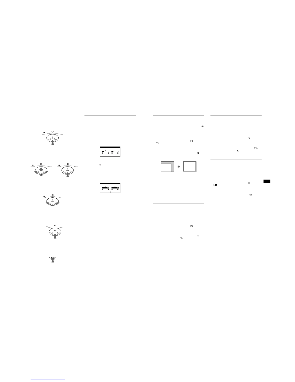
x Using the control button
1
Display the main MENU.
Press the center of the control button to display the main
MENU on your screen.
2
Select the menu you want to adjust.
Highlight the desired menu by moving the control button
towards the rear to go up (M), towards the front to go down
(m), and left (<) or right (,) to move sideways.
3
Adjust the menu.
Move the control button left ( < ) or right ( ,
) to make the
adjustment.
4
Close the menu.
Press the center of the control button once to return to the
main MENU, and twice to return to normal viewing. If no
buttons are pressed, the menu closes automatically after about
30 seconds.
x
Resetting the adjustments
Press the RESET button. See page 16 for more information on
resetting the adjustments.
Adjusting the brightness and
contrast
Brightness and contrast adjustments are made using a separate
BRIGHTNESS/CONTRAST menu.
These settings are stored in memory for the signals from the
currently selected input connector.
1
Move the control button in any direction.
The BRIGHTNESS/CONTRAST menu appears on the
screen.
2
Move the control button m / M to adjust the
brightness ( ), and < / , to adjust the contrast
(
6
).
If you are using the sRGB mode
If you selected the sRGB mode in the COLOR menu, the
following BRIGHTNESS/CONTRAST menu appears on the
screen.
For more information about using the sRGB mode, see
“Adjusting the color of the picture (COLOR)” on page 13.
The menu automatically disappears after about 3 seconds.
MENU
MENU
MENU
REAR
FRONT
MENU
MENU
RESET
26 26
BRI GHTNESS / CONTRAST
56 76
sRGB : 56 76
BRI GHTNESS / CONTRAST
11
US
Automatically sizing and centering
the picture (AUTO)
You can easily adjust the picture to fill the screen by using the
(AUTO) item in the SIZE/CENTER menu.
1
Press the center of the control button.
The main MENU appears on the screen.
2
Move the control button to highlight SIZE or
CENTER and press the center of the control
button again.
The SIZE/CENTER menu appears on the screen.
3
First move the control button m/M to select
(AUTO). Then move the control button , .
The picture automatically fills the screen.
Notes
• This function is intended for use with a computer running Windows or
similar graphic user interface software that provides a full-screen
picture. It may not work properly if the background color is dark or if
the input picture does not fill the screen to the edges (such as an MSDOS prompt).
• Pictures with an aspect ratio of 5:4 (resolution: 1280 × 1024, 1600 ×
1280) are displayed at their actual resolution and do not fill the screen
to the edges.
• The displayed image moves for a few seconds while this function is
performed. This is not a malfunction.
Adjusting the size of the picture
(SIZE)
This setting is stored in memory for the current input signal.
1
Press the center of the control button.
The main MENU appears on the screen.
2
Move the control button to highlight SIZE and
press the center of the control button again.
The SIZE/CENTER menu appears on the screen.
3
First move the control button m / M to select for
horizontal adjustment, or for vertical
adjustment. Then move the control button < / , to
adjust the size.
Adjusting the centering of the
picture (CENTER)
This setting is stored in memory for the current input signal.
1
Press the center of the control button.
The main MENU appears on the screen.
2
Move the control button to highlight CENTER
and press the center of the control button again.
The SIZE/CENTER menu appears on the screen.
3
First move the control button m / M to select for
horizontal adjustment, or for vertical adjustment.
Then move the control button < / , to adjust the
centering.
Enlarging or reducing the picture
(ZOOM)
This setting is stored in memory for the current input signal.
1
Press the center of the control button.
The main MENU appears on the screen.
2
Move the control button to highlight SIZE or
CENTER and press the center of the control
button again.
The SIZE/CENTER menu appears on the screen.
3
Move the control button m / M to select (zoom),
and move < / , to enlarge or reduce the picture.
Note
Adjustment stops when either the horizontal or vertical size reaches its
maximum or minimum value.
1-5
12
Adjusting the shape of the picture
(GEOM)
The GEOM settings allow you to adjust the rotation and shape of
the picture.
The (rotation) setting is stored in memory for all input signals.
All other settings are stored in memory for the current input
signal.
1
Press the center of the control button.
The main MENU appears on the screen.
2
Move the control button to highlight GEOM and
press the center of the control button again.
The GEOMETRY menu appears on the screen.
3
First move the control button m/M to select the
desired adjustment item. Then move the control
button </ , to make the adjustment.
Adjusting the convergence (CONV)
The CONV settings allow you to adjust the quality of the picture
by controlling the convergence. The convergence refers to the
alignment of the red, green, and blue color signals.
If you see red or blue shadows around letters or lines, adjust the
convergence.
These settings are stored in memory for all input signals.
1
Press the center of the control button.
The main MENU appears on the screen.
2
Move the control button to highlight CONV and
press the center of the control button again.
The CONVERGENCE menu appears on the screen.
3
First move the control button m / M to select the
desired adjustment item. Then move the control
button < / , to make the adjustment.
Select To
rotate the picture
expand or contract the picture sides
shift the picture sides to the left or right
adjust the picture width at the top of the screen
shift the picture to the left or right at the top of the
screen
Select To
horizontally shift red or blue shadows
vertically shift red or blue shadows
TOP
V CONVER TOP
vertically shift red or blue shadows at
the top of the screen
BOT
V CONVER
BOTTOM
vertically shift red or blue shadows at
the bottom of the screen
13
US
Adjusting the quality of the picture
(SCREEN)
The SCREEN settings allow you to adjust the quality of the
picture by controlling the moire and landing.
• If the color is irregular at the corners of the screen, adjust the
landing.
• If elliptical or wavy patterns appear on the screen, cancel the
moire.
The CANCEL MOIRE and MOIRE ADJUST settings are stored
in memory for the current input signal. All other settings are
stored in memory for all input signals.
1
Press the center of the control button.
The main MENU appears on the screen.
2
Move the control button to highlight SCREEN
and press the center of the control button again.
The SCREEN menu appears on the screen.
3
First move the control button m/ M to select the
desired adjustment item. Then move the control
button < / , to make the adjustment.
• Moire is a type of natural interference which produces soft, wavy lines
on your screen. It may appear due to interference between the pattern
of the picture on the screen and the phosphor pitch pattern of the
monitor.
Note
The picture may become fuzzy when CANCEL MOIRE is set to ON.
Adjusting the color of the picture
(COLOR)
The COLOR settings allow you to adjust the picture’s color
temperature by changing the color level of the white color field.
Colors appear reddish if the temperature is low, and bluish if the
temperature is high. This adjustment is useful for matching the
monitor’s color to a printed picture’s colors.
1
Press the center of the control button.
The main MENU appears on the screen.
2
Move the control button to highlight COLOR and
press the center of the control button again.
The COLOR menu appears on the screen.
3
Move the control button < / , to select the
adjustment mode.
There are three types of adjustment modes, EASY, EXPERT
and sRGB.
4
First move the control button m / M to select the
desired adjustment item. Then move the control
button < / , to make the adjustment.
Adjust the selected mode according to the following
instructions.
EASY mode
1
Move the control button m / M to select the color
temperature row 1 . Then move the control button
< / ,
to select a color temperature.
The preset color temperatures are 5000K, 6500K, and 9300K.
Since the default setting is 9300K, the whites will change
from a bluish hue to a reddish hue as the temperature is
lowered to 6500K and 5000K.
2
If necessary, fine tune the color temperature.
Move the control button m
/ M
to select the color
temperature row 2 . Then move the control button
< / ,
to fine tune the color temperature.
If you fine tune the color temperature, the new color settings
are stored in memory for each of the three color temperatures
and item 1 of the on-screen menu changes as follows.
• [5000K] t [1]
• [6500K] t [2]
• [9300K] t [3]
Select To
LANDING
reduce any color irregularities in the
screen’s top left corner to a minimum.
LANDING
reduce any color irregularities in the
screen’s top right corner to a
minimum.
LANDING
reduce any color irregularities in the
screen’s bottom left corner to a
minimum.
LANDING
reduce any color irregularities in the
screen’s bottom right corner to a
minimum.
CANCEL MOIRE*
turn the moire cancellation function
ON or OFF.
(MOIRE ADJUST) appears in
the menu when you select ON.
MOIRE ADJUST
adjust the degree of moire
cancellation until the moire is at a
minimum.
Example of moire
EASY EXPERT s BGR
5000K 6500K 930 K0
50 K00
IMAGE
RESTORATI ON ON
COLOR
(continued)

1-6
14
EXPERT mode
You can make additional adjustments to the color in greater detail
by selecting the EXPERT mode.
1
Move the control button m/M to select the color
temperature row 1. Then move the control button
</, to select a color temperature.
2
Move the control button m / M to select the
adjustment item 2 . Then move the control button
< / ,
to adjust the BIAS (black level).
This adjusts the dark areas of an image.
3
Move the control button m / M to select the
adjustment item 3 . Then move the control button
< / ,
to adjust the GAIN (white level).
This adjusts the light areas of an image.
You can adjust the R (red), G (green), B (blue) component of
the input signal when making changes to items 2 and 3 .
If you fine tune the color temperature, the new color settings
are stored in memory for each of the three color temperatures
and item 1 of the on-screen menu change as follows.
• [5000K] t [1]
• [6500K] t [2]
• [9300K] t [3]
Setting the color temperature for each of the
video input connectors
You can set the fine tuning of the color temperature in EASY or
EXPERT mode for each of the video input connectors (HD15 and
BNC).
1
Select the same adjustment mode and color
temperature in the COLOR menu for both HD15 and
BNC.
2
Fine tune the color temperature in each menu for
HD15 and BNC.
The settings are stored in memory for each of the HD15 and
BNC connectors.
For information on how to select the connector, see page 8.
sRGB mode
The sRGB color setting is an industry standard color space
protocol designed to correlate the displayed and printed colors of
sRGB compliant computer products. To adjust the colors to the
sRGB profile, simply select the sRGB mode in the COLOR menu.
However, in order to display the sRGB colors correctly ( γ =2.2,
6500K), you must set your computer to the sRGB profile and
adjust the brightness ( ) and contrast ( 6 ) to the numbers shown
in the menu. For information on how to change the brightness
( ) and contrast ( 6 ), see page 10.
Note
Your computer and other connected products (such as a printer), must be
sRGB compliant.
EASY EXPERT s BGR
5000K 6500K 930 K0
R BIAS 05
G BIAS 05
B BIAS 05
RGAIN 05
GGAIN 05
BGAIN 05
COLOR
EASY EXPERT s BGR
:56 :76 FOR s BGR
IMAGE
RESTORATI ON ON
COLOR
15
US
Restoring the color from the EASY or sRGB menus
The colors of most display monitors tend to gradually lose brilliance
over several years of service. The IMAGE RESTORATION feature
found in the EASY and sRGB menus allows you to restore the color
to the original factory quality levels. The explanation below
explains how to restore the monitor’s color from the EASY menu.
1
Move the control button </, to select EASY or
sRGB mode.
2
First move the control button m/M to select
(IMAGE RESTORATION). Then move the control
button , .
The picture disappears while the color is being restored (about
2 seconds). After the color is restored, the picture reappears
on the screen again.
Notes
• Before using this feature, the monitor must be in normal operation
mode (green power indicator on) for at least 30 minutes. If the monitor
goes into power saving mode, you must return the monitor to normal
operation mode and wait for 30 minutes for the monitor to be ready.
You may need to adjust your computer’s power saving settings to keep
the monitor in normal operation mode for the full 30 minutes. If the
monitor is not ready, the following message will appear.
• The monitor may gradually lose its ability to perform this function due
to the natural aging of the picture tube.
Additional settings (OPTION)
You can manually degauss (demagnetize) the monitor, change the
menu position, and lock the controls.
1
Press the center of the control button.
The main MENU appears on the screen.
2
Move the control button to highlight OPTION and
press the center of the control button again.
The OPTION menu appears on the screen.
3
Move the control button m / M to select the desired
adjustment item.
Adjust the selected item according to the following
instructions.
Degaussing the screen
The monitor is automatically demagnetized (degaussed) when the
power is turned on.
To manually degauss the monitor, first move the
control button m / M to select (DEGAUSS). Then move
the control button , .
The screen is degaussed for about 2 seconds. If a second degauss
cycle is needed, allow a minimum interval of 20 minutes for the
best result.
Changing the menu’s position
Change the menu’s position if it is blocking an image on the
screen.
To change the menu’s on-screen position, first move
the control button m / M to select (OSD H POSITION)
for horizontal adjustment, or (OSD V POSITION) for
vertical adjustment. Then move the control button
< / ,
to shift the on-screen menu.
Locking the controls
To protect adjustment data by locking the controls, first
move the control button m / M to select (CONTROL
LOCK). Then move the control button
, , to select ON.
Only the 1 (power) switch, EXIT, and (CONTROL LOCK)
of the OPTION menu will operate. If any other items are
selected, the mark appears on the screen.
To cancel the control lock
Repeat the procedure above and set (CONTROL LOCK) to OFF.
EASY EXPERT s BGR
5000K 6500K 930 K0
50 K00
IMAGE
RESTORATI ON
AVAI LABLE
AFTER WARM UP
COLOR
1-7
16
Resetting the adjustments
This monitor has the following three reset methods. Use the
RESET button to reset the adjustments.
Resetting a single adjustment item
Use the control button to select the adjustment item you want to
reset, and press the RESET button.
Resetting all of the adjustment data for the
current input signal
Press the RESET button when no menu is displayed on the screen.
Note that the following items are not reset by this method:
• on-screen menu language (page 8)
• adjustment mode in the COLOR menu (EASY, EXPERT,
sRGB) (page 13)
• on-screen menu position (page 15)
• control lock (page 15)
Resetting all of the adjustment data for all input
signals
Press and hold the RESET button for more than two seconds.
Note
The RESET button does not function when
(CONTROL LOCK)
is set to ON.
Technical Features
Preset and user modes
When the monitor receives an input signal, it automatically
matches the signal to one of the factory preset modes stored in the
monitor’s memory to provide a high quality picture at the center of
the screen.
(See Appendix for a list of the factory preset modes.)
For input signals that do not match one of the factory preset modes,
the digital Multiscan technology of this monitor ensures that a
clear picture appears on the screen for any timing in the monitor’s
frequency range (horizontal: 30 – 121 kHz, vertical: 48 – 160 Hz).
If the picture is adjusted, the adjustment data is stored as a user
mode and automatically recalled whenever the same input signal
is received.
Note for Windows users
For Windows users, check your video board manual or the utility
program which comes with your graphic board and select the
highest available refresh rate to maximize monitor performance.
Power saving function
This monitor meets the power-saving guidelines set by VESA,
E
NERGY
S
TAR, and NUTEK. If the monitor is connected to a
computer or video graphics board that is DPMS (Display Power
Management Signaling) compliant, the monitor will automatically
reduce power consumption in three stages as shown below
.
* “Sleep” and “deep sleep” are power saving modes defined by the
Environmental Protection Agency.
** When your computer enters a power saving mode, the input signal is
cut and NO INPUT SIGNAL appears on the screen. After a few
seconds, the monitor enters a power saving mode.
RESET
Power mode Power consumption 1 (power)
indicator
normal
operation
≤
145 W green
1 standby ≤ 100 W green and orange
alternate
2 suspend
(sleep)*
≤
15 W green and orange
alternate
3 active off**
(deep sleep)*
Approx. 1 W orange
power off 0 W off
17
US
Troubleshooting
Before contacting technical support, refer to this section.
If thin lines appear on your screen
(damper wires)
The lines you are experiencing on your screen are normal for the
Trinitron monitor and are not a malfunction. These are shadows
from the damper wires used to stabilize the aperture grille and are
most noticeable when the screen’s background is light (usually
white). The aperture grille is the essential element that makes a
Trinitron picture tube unique by allowing more light to reach the
screen, resulting in a brighter, more detailed picture.
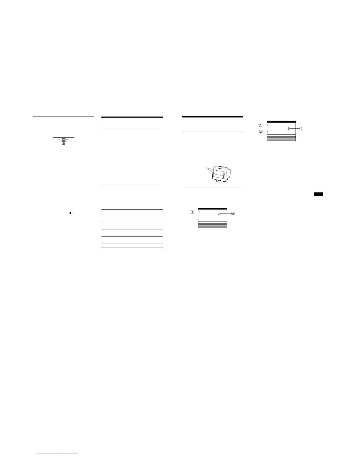
On-screen messages
If there is something wrong with the input signal, one of the
following messages appears on the screen.
If NO INPUT SIGNAL appears on the screen
If OUT OF SCAN RANGE appears on the screen
For more information, see “Trouble symptoms and remedies” on
page 18.
1 The selected connector
This message shows the currently selected connector
(HD15 or BNC).
2
The input signal condition
NO INPUT SINGAL
This indicates that no signal is input, or that no signal is input
from the selected connector.
Damper wires
MONI TOR IS WORKI NG
HD15 :
NO INPUT S I GNAL
WH I TE
RED
GREEN
BLUE
INFORMATION
1
The selected connector and the frequencies of the
current input signal
This message shows the currently selected connector
(HD15 or BNC). If the monitor recognizes the frequencies of
the current input signal, the horizontal and vertical
frequencies are also displayed.
2
The input signal condition
OUT OF SCAN RANGE
This indicates that the input signal is not supported by the
monitor’s specifications.
3
The remedies
CHANGE SIGNAL TIMING appears on the screen. If you
are replacing an old monitor with this monitor, reconnect the
old monitor. Then adjust the computer’s graphic board so that
the horizontal frequency is between 30 - 121 kHz, and the
vertical frequency is between 48 - 160 Hz.
MONI TOR IS WORKI NG
BNC :130.0kHz/ H57
OUT OF SCAN RANGE
CHANGE S IGN AL T IM I NG
WH I TE
RED
GREEN
BLUE
INFORMATION
z

1-8
18
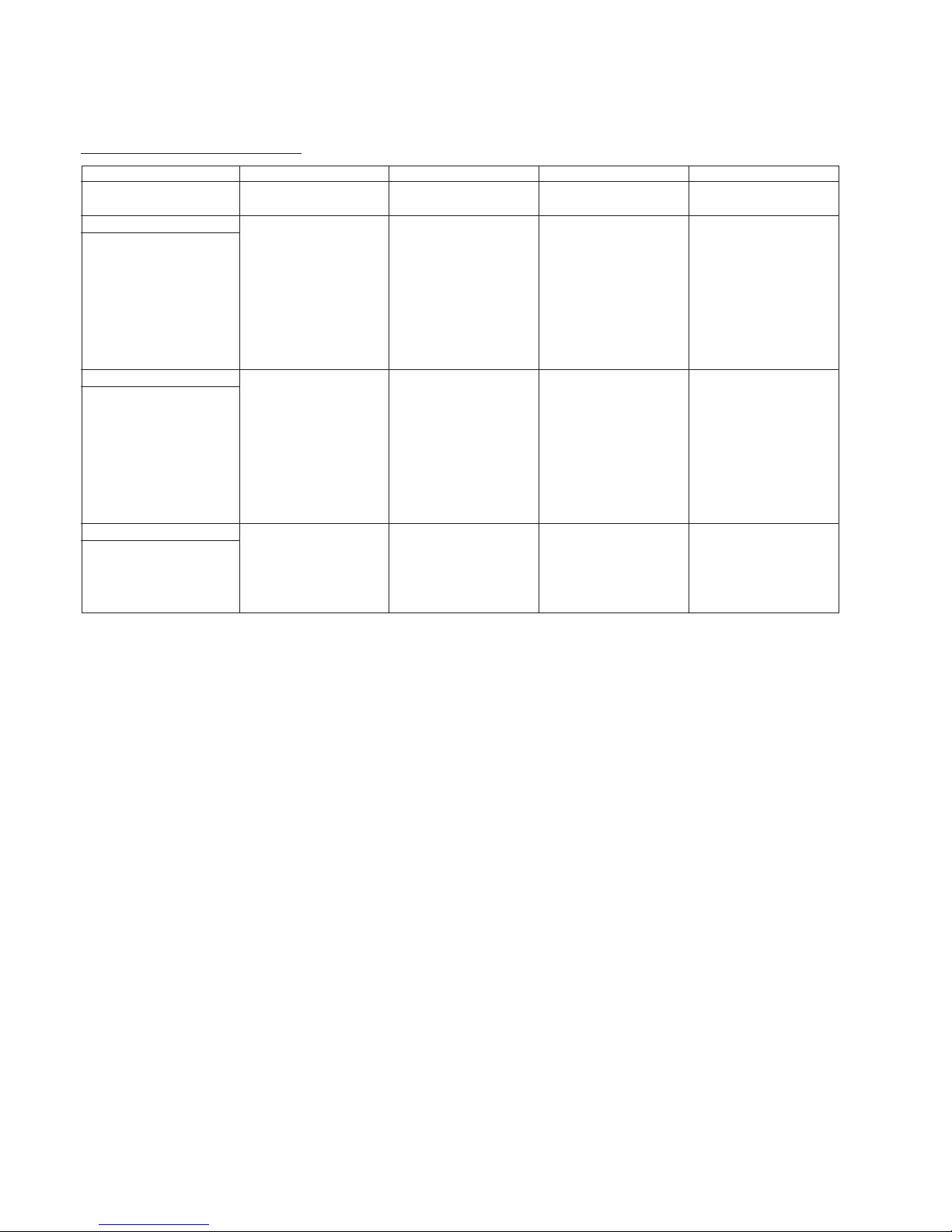
Trouble symptoms and remedies
If the problem is caused by the connected computer or other equipment, please refer to the connected equipment’s instruction manual.
Use the self-diagnosis function (page 20) if the following recommendations do not resolve the problem.
Symptom Check these items
No picture
If the 1 (power) indicator is not lit • Check that the power cord is properly connected.
• Check that the 1 (power) switch is in the “on” position.
If the NO INPUT SIGNAL message
appears on the screen, or if the 1
(power) indicator is either orange or
alternating between green and
orange
• Check that the video signal cable is properly connected and all plugs are firmly seated in
their sockets. If you are using the five BNC connectors, connect them in the correct order
(from left to right: Red-Green-Blue-HD-VD) (page 6).
• Check that the INPUT switch setting is correct (page 8).
• Check that the HD15 video input connector’s pins are not bent or pushed in.
xProblems caused by the connected computer or other equipment
• The computer is in power saving mode. Try pressing any key on the computer keyboard.
• Check that the computer’s power is “on.”
• Check that the graphic board is completely seated in the proper bus slot.
If the OUT OF SCAN RANGE
message appears on the screen
xProblems caused by the connected computer or other equipment
• Check that the video frequency range is within that specified for the monitor. If you
replaced an old monitor with this monitor, reconnect the old monitor and adjust the
frequency range to the following.
Horizontal: 30 – 121 kHz
Vertical: 48
–
160 Hz
If no message is displayed and the 1
(power) indicator is green or flashing
orange
• Use the Self-diagnosis function (page 20).
If using Windows 95/98 • If you replaced an old monitor with this monitor, reconnect the old monitor and do the
following. Install the Windows Monitor Information Disk (page 7) and select this monitor
(“CPD-G500/G500J”) from among the Sony monitors in the Windows 95/98 monitor
selection screen. If you choose to select “Plug and Play,” connect the monitor to the
computer with the HD15 video signal cable. You cannot use the five BNC connectors.
If using a Macintosh system • Check that the Macintosh adapter and the video signal cable are properly connected
(page 6).
Picture flickers, bounces,
oscillates, or is scrambled
• Isolate and eliminate any potential sources of electric or magnetic fields such as other
monitors, laser printers, electric fans, fluorescent lighting, or televisions.
• Move the monitor away from power lines or place a magnetic shield near the monitor.
• Try plugging the monitor into a different AC outlet, preferably on a different circuit.
• Try turning the monitor 90° to the left or right.
x
Problems caused by the connected computer or other equipment
• Check your graphics board manual for the proper monitor setting.
• Confirm that the graphics mode (VESA, Macintosh 21" Color, etc.) and the frequency of
the input signal are supported by this monitor (Appendix). Even if the frequency is within
the proper range, some video boards may have a sync pulse that is too narrow for the
monitor to sync correctly.
• Adjust the computer’s refresh rate (vertical frequency) to obtain the best possible picture.
Picture is fuzzy
• Adjust the brightness and contrast (page 10).
• Degauss the monitor* (page 15).
• If CANCEL MOIRE is ON, the picture may become fuzzy. Decrease the moire
cancellation effect or set CANCEL MOIRE to OFF (page 13).
19
US
* If a second degauss cycle is needed, allow a minimum interval of 20 minutes for the best result. A humming noise may be heard, but this is not a
malfunction.
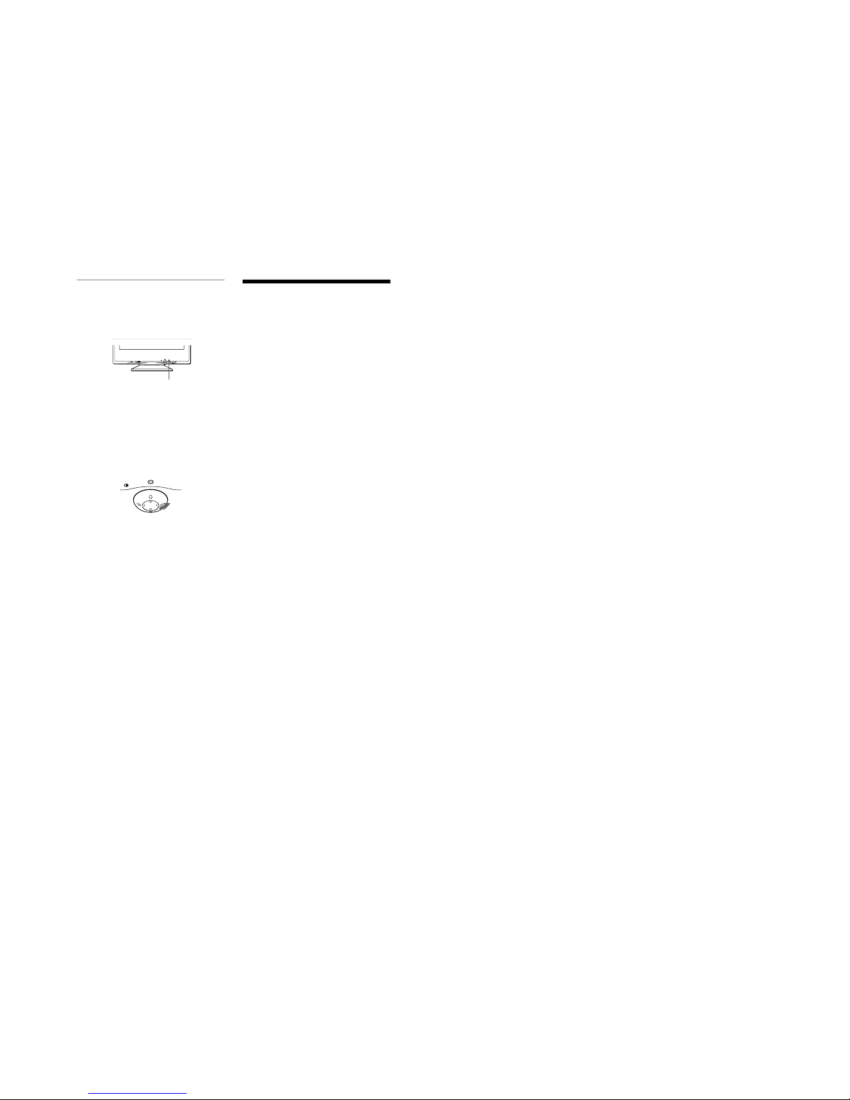
Displaying this monitor’s name, serial number,
and date of manufacture.
While the monitor is receiving a video signal, press and hold the
center of the control button for more than five seconds to display
this monitor’s information box.
If the problem persists, call your authorized Sony dealer and give
the following information.
• Model name: CPD-G500
• Serial number
• Name and specifications of your computer and graphics board.
Picture is ghosting • Eliminate the use of video cable extensions and/or video switch boxes.
• Check that all plugs are firmly seated in their sockets.
Picture is not centered or sized
properly
• Perform the (AUTO) function (page 11).
• Adjust the size (page 11) or centering (page 11). Note that some video modes do not fill
the screen to the edges.
Edges of the image are curved • Adjust the geometry (page 12).
Wavy or elliptical pattern (moire)
is visible
• Set CANCEL MOIRE to ON and adjust the degree of moire cancellation until the moire is
at a minimum (page 13).
xProblems caused by the connected computer or other equipment
• Change your desktop pattern.
Color is not uniform
• Degauss the monitor* (page 15). If you place equipment that generates a magnetic field,
such as a speaker, near the monitor, or if you change the direction the monitor faces, color
may lose uniformity.
• Adjust the landing (page 13).
White does not look white
• Adjust the color temperature (page 13).
• Check that the five BNC connectors are connected in the correct order (from left to right:
Red-Green-Blue-HD-VD) (page 6).
Letters and lines show red or blue
shadows at the edges
• Adjust the convergence (page 12).
Monitor buttons do not operate
( appears on the screen)
• If the control lock is set to ON, set it to OFF (page 15).
COLOR RETURN function does
not operate
• Before using this function, the monitor must be in normal operation mode (green power
indicator on) for at least 30 minutes. For more information on using the IMAGE
RESTORATION function, see page 15.
• Adjust the computer’s power saving settings to keep the monitor in normal operation
mode for more than 30 minutes.
• The monitor may gradually lose its ability to perform this function due to the natural aging
of the picture tube.
A hum is heard right after the
power is turned on
• This is the sound of the auto-degauss cycle. When the power is turned on, the monitor is
automatically degaussed for two seconds.
Symptom Check these items
EASY EXPERT s BGR
5000K 6500K 930 K0
50 K00
IMAGE
RESTORATI ON
AVAI LABLE
AFTER WARM UP
COLOR
MENU
SER NO
:
1234567
MODEL
:
CPD G500
MANUFACTURED
: 1999-52
INFORMATION
Example
b
1-9
20
Self-diagnosis function
This monitor is equipped with a self-diagnosis function. If there is
a problem with your monitor or computer(s), the screen will go
blank and the 1 (power) indicator will either light up green or
flash orange. If the 1 (power) indicator is lit in orange, the
computer is in power saving mode. Try pressing any key on the
keyboard.
If the 1 (power) indicator is green
1
Remove any plugs from the video input 1 and 2
connectors, or turn off the connected computer(s).
2
Press the 1 (power) button twice to turn the monitor
off and then on.
3
Move the control button , for 2 seconds before the
monitor enters power saving mode.
If all four color bars appear (white, red, green, blue), the monitor
is working properly. Reconnect the video input cables and check
the condition of your computer(s).
If the color bars do not appear, there is a potential monitor failure.
Inform your authorized Sony dealer of the monitor’s condition.
If the 1 (power) indicator is flashing orange
Press the 1 (power) button twice to turn the monitor off
and then on.
If the 1 (power) indicator lights up green, the monitor is working
properly.
If the 1 (power) indicator is still flashing, there is a potential
monitor failure. Count the number of seconds between orange
flashes of the 1 (power) indicator and inform your authorized
Sony dealer of the monitor’s condition. Be sure to note the model
name and serial number of your monitor. Also note the make and
model of your computer and video board.
Specifications
CRT 0.24 mm aperture grille pitch
21 inches measured diagonally
90-degree deflection
FD Trinitron
Viewable image size Approx. 403.8 × 302.2 mm (w/h)
(16 × 12 inches)
19.8" viewing image
Resolution
Maximum Horizontal: 2048 dots
Vertical: 1536 lines
Recommended Horizontal: 1600 dots
Vertical: 1200 lines
Standard image area Approx. 388 × 291 mm (w/h)
(15
3
/
8
×
11
1
/
2
inches)
or
Approx. 364 × 291 mm (w/h)
(14
3
/
8
×
11
1
/
2
inches)
Deflection frequency* Horizontal: 30 to 121 kHz
Vertical: 48 to 160 Hz
AC input voltage/current 100 to 240 V, 50 – 60 Hz, 2.0 – 1.0 A
Power consumption Approx. 145 W
Dimensions
Approx. 497
×
480 × 478 mm (w/h/d)
(19
5
/
8
×
19 × 18
7
/
8
inches)
Mass Approx. 32 kg (70 lb 9 oz)
Plug and Play DDC1/2B/2Bi, GTF**
Supplied accessories See page 6
* Recommended horizontal and vertical timing condition
• Horizontal sync width duty should be more than 4.8% of total
horizontal time or 0.8 µs, whichever is larger.
• Horizontal blanking width should be more than 2.3 µsec.
• Vertical blanking width should be more than 450 µsec.
** If the input signal is Generalized Timing Formula (GTF)
compliant, the GTF feature of the monitor will automatically
provide an optimal image for the screen.
Design and specifications are subject to change without notice.
MENU
RESET
INPUTHD15BNC
1 (power) indicator
MENU

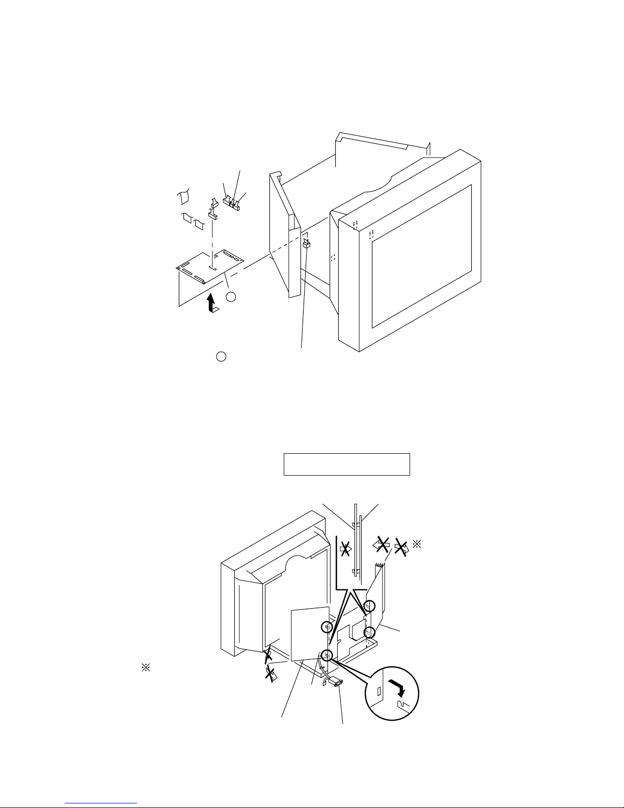
2-1. CABINET REMOVAL
4
Four screws
(+ BVTT 4 x 8)
5
Top cover
SECTION 2
DISASSEMBLY
Push in the tip of a screwdriver
about 5mm to unlock the claw.
Cabinet
Bezel assembly Bezel assembly
3
2
Two claws
6
Three screws
(+ BVTT 4 x 8)
7
Video shield
Cabinet
1
Two screws
(+ BVTP 4 x 16)
Cabinet
2
Two claws
CPD-G500
2-2. D BOARD REMOVAL
4
3
Screw
(+ P 3.5 x 20)
5
D board
GND
Two screws
(+ BVTP 3 x 12)
1
Three screws
(+ BVTT 4 x 8)
Two hooks
2
B
CN504
CN505
A
Open the D block in the direction
of the arrow . and remove of
the arrow .
A
B
2-1
CPD-G500
2-3. G BOARD REMOVAL
1
Three screws
(+ BVTT 4 x 8)
CN654
CN653
CN652
Four screws
3
(+BVTP 3 x 8)
4
G shield
CN602
6
B
G board
CN650
GND
GND
A
Two hooks
2
Open the G block in the direction
of the arrow . and remove of
the arrow .
A
B
5
Two printed circuit board holders
2-4. A BOARD, I/O TERMINAL BOARD ASSEMBLY REMOVAL
3
A board (2/2)
7
Two screws
(+ BVTP 3 x 8)
8
AC inlet (3P)
2
A board (1/2)
When installing I/O terminal
board assembly, be sure to apply
screw lock on 2 spots after
screws (HD15) are fixed.
A board (1/2)
Screw lock
A board (1/2)
5
4
Two screws
(HD15)
2-2
1
Four screws
(+BVTT 4 x 8)
I/O terminal board assembly
2-5. N BOARD REMOVAL
CN001
CN5002
CN002
CPD-G500
CN5003
CN5001
CN010
CN011
2-6. SERVICE POSITION
CN007
2
N board
1
Printed circuit board holder
CAUTION : SHORT
D,G boards
Rear shield
If the claw is hooked,
opening and closing
the board is impossible.
Do not try to do it by force.
CN602
G board
(Refer to 2-3.)
If the claw is hooked,
opening and closing
the board is impossible.
Do not try to do it by force.
D board (Refer to 2-2.)
AC inlet (3P)
2-3
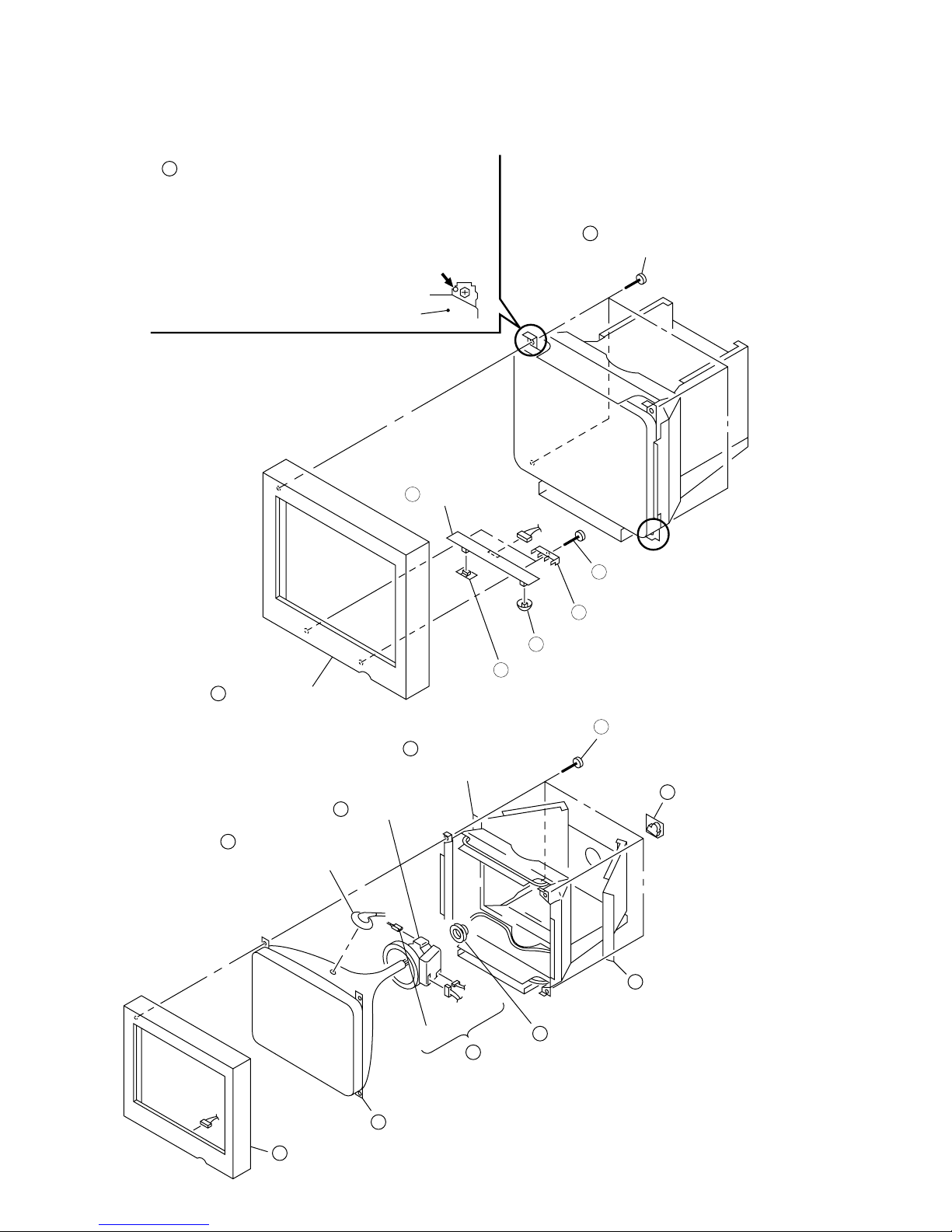
CPD-G500
y
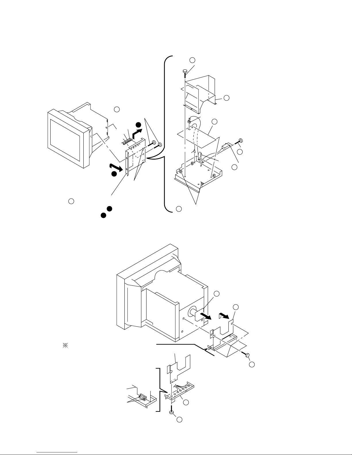
2-7. BEZEL ASSEMBLY, H1 BOARD REMOVAL
1
Before removing the bezel assembly, secure
the picture tube by attaching two screws to
the picture tube shield at the positions
shown with an arrow (diagonal two places)
to prevent the picture tube from falling. (Use
the screws +BVTT 4 x 8 that fix top cover.)
Picture tube shield
6
H1 board
CN801
2
Four screws
(Tapping screw 5)
3
Bezel assembl
2-8. PICTURE TUBE REMOVAL
10
5
Anode cap
(See page 2-5.)
1
Open the D block.
(Refer to 2-2.)
Deflection yoke
GND
7
Input selection
CN4
CN5
4
Three connectors
4
5
Two H printed circuit board brackets
8
Menu button
6
Neck assembly
9
Two screws
(+ BVTP 4 x 16)
Four screws
(Tapping screw 5)
3
A board
2
Open the G block.
(Refer to 2-3.)
CN801
7
Bezel assembly
8
Picture tube
2-4
CPD-G500
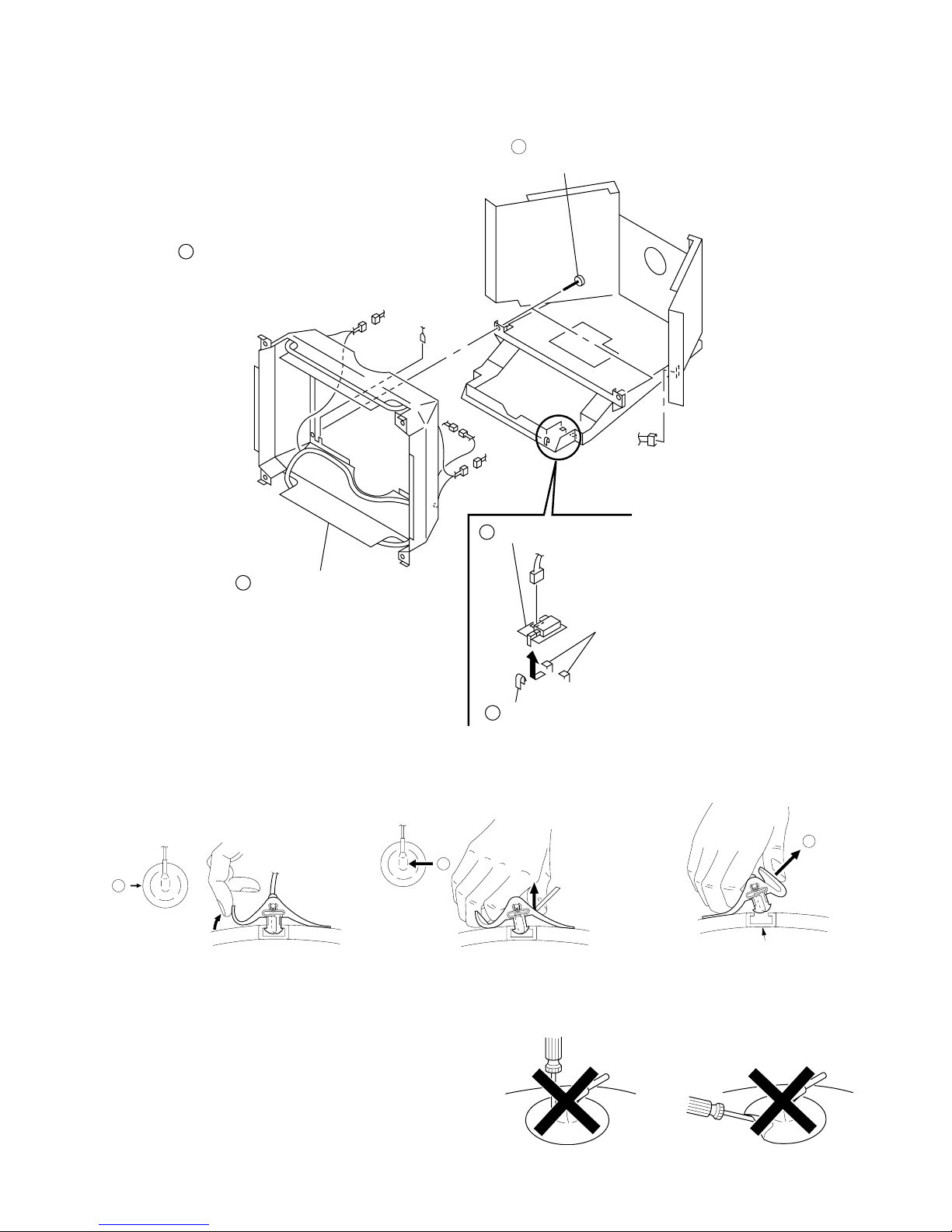
2-9. J BOARD REMOVAL
1
Remove the picture tube.
(Refer to 2-8.)
3
Picture tube shield
complete assembly.
4pin
GND
2pin
4pin
5
J board
2
Two screws
(+BVTT 4 x 8)
CN601
CN891
Two hooks
4
Claw
• REMOVAL OF ANODE-CAP
NOTE: Short circuit the anode of the picture tube and the anode cap to the metal chassis, CRT shield or carbon painted on the CRT, after
removing the anode.
• REMOVING PROCEDURES
c
b
a
Anode Button
1 Turn up one side of the rubber cap in
the direction indicated by the arrow a.
2 Using a thumb pull up the rubber cap
firmly in the direction indicated by the
arrow b.
• HOW TO HANDLE AN ANODE-CAP
1 Don’t scratch the surface of anode-caps with shartp shaped
material!
2 Don’t press the rubber hardly not to damage inside of anode-
caps!
A material fitting called as shatter-hook terminal is built in the
rubber.
3 Don’t turn the foot of rubber over hardly!
The shatter-hook terminal will stick out or damage the rubber.
3 When one side of the rubber cap is
separated from the anode button, the
anode-cap can be removed by turning
up the rubber cap and pulling up it in the
direction of the arrow c.
2-5
 Loading...