

Sony TRINITRON CPD-E210 Service Manual
SERVICE MANUAL
CPD-E210
CPD-E210
US Model
Canadian Model
Chassis No. SCC-L31A-A
Picture tube
Video image area
Resolution
Standard image area
Input signal
Video
Sync
SPECIFICATIONS
0.24 mm aperture grill pitch
17 inches measured diagonally
90-degree deflection
(16" maximum viewing image)
Approx. 327 X 243 mm (w/h)
9/10
1/2
x 9
x 9
1/4
±
inches)
inches)
5%, Positive
(12
Horizontal: Max. 1600 dots
Vertical: Max. 1200 lines
Approx. 312 x 234 mm (w/h)
1/4
(12
Analog RGB (75 ohms typical)
0.7 Vp-p,
Separate HD/VD,
TTL Polarity Free
External Composite,
TTL Polarity Free (2K ohms impedance)
D99C
Deflection frequency
AC input v oltage / current
Dimensions
Mass
Plug and Play
Design and specifications are subject to change without notice.
CHASSIS
Horizontal: 30 to 85 KHz
Vertical: 48 to 120 Hz
100 to 120 V, 50/60 Hz, 1.7A
220 to 240V, 50/60Hz, 0.9A
404 x 413.5 x 419.5mm (w/h/d)
9/10
3/10
(15
x 16
Approx. 20.0 kg (44 lb 2 oz.)
DDC/DDC2B, DDC2Bi, GTF
x 16
1/2
inches)
TRINITRON® COLOR MONITOR
CPD-E210
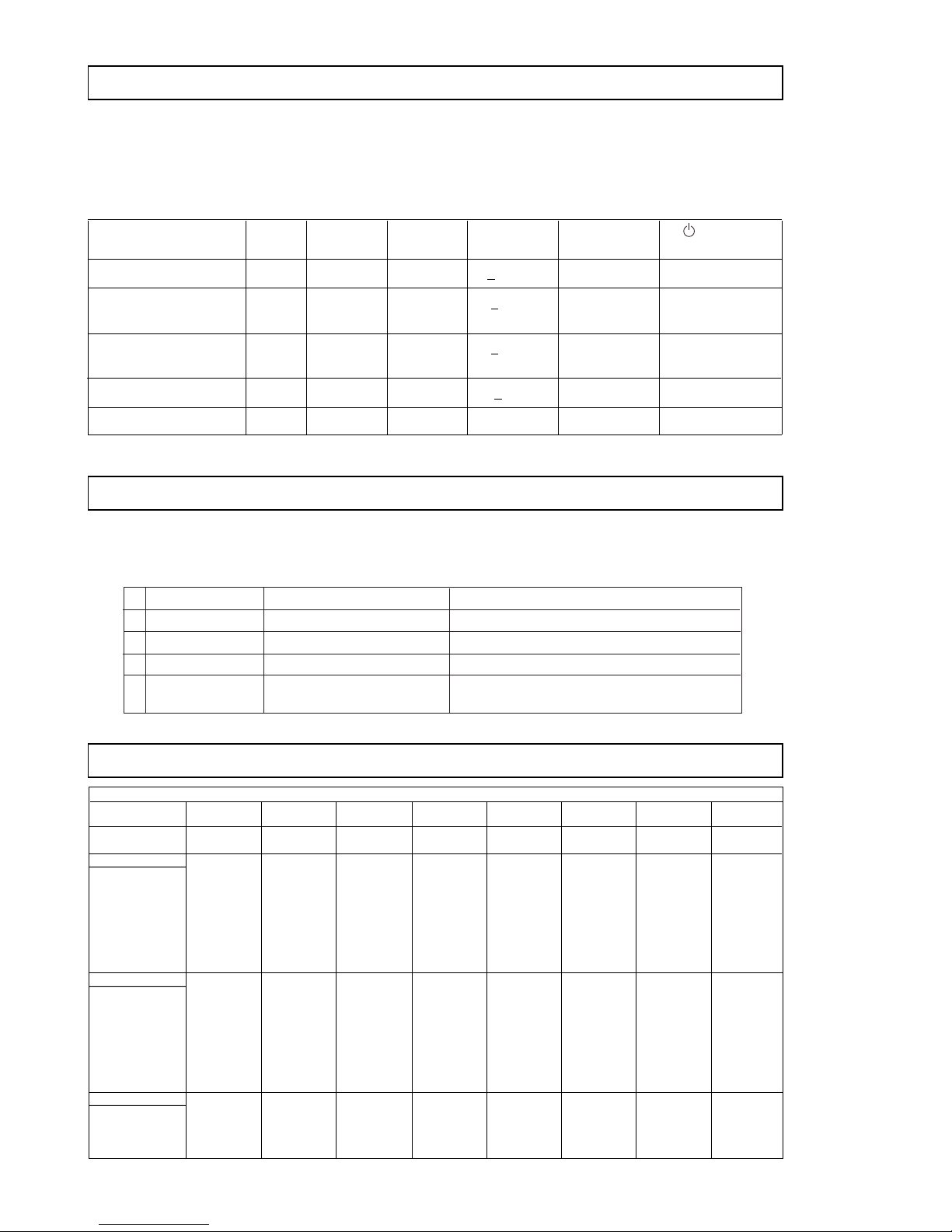
1 Normal operation active yes yes < 120 W -- Green
POWER MANAGEMENT
The power saving mode complies with the VESA Display P ower Management Signaling standard. Each
state of power management shall be activated by the host computer terminating the appropriate sync
signals. Blanking the video must precede termination of the sync signals. The elapsed time counter
shall also be controlled by the host computer. Reactivation of the monitor shall be accomplished from
the host computer by re-establishing the normal sync signal.
Power consumption Screen Horizontal Vertical Power Recovery time indicator
mode (video) sync signal sync signal consumption
2 Standby (1st mode) blank no yes < 15 W Approx. 5 sec. Green and Orange
3 Suspend (2nd mode) blank yes no < 15 W Approx. 5 sec. Green and Orange
4 Active-off (3rd mode) blank no no < 3 W Approx. 10 sec. Orange
5 Power-off -- -- -- 0 W -- Off
Alternate
Alternate
SELF DIAGNOSIS FUNCTION
When a failure occurs, the STANDBY/TIMER lamp will flash a set number of times to indicate the
possible cause of the problem. If there is more than one error, the lamp will identify the first of the
problem areas.
Status Area of Failure LED Indication
1 Failure 1 HV or +B Amber (0.5 second)/Off (0.5 second)
2 Failure 2 Amber (1.5 second)/Off (0.5 second)
3 Failure 3 ABL Amber (0.5 second)/Off (1.5 second)
4 Aging/Self Test Amber (0.5 second)/Off (0.5 second)/
H Stop or V Stop
Green (0.5 second)/Off (0.5 second)
TIMING SPECIFICATION
MODE 12345678
Resolution (H x V) 640 X 480 800 X 600 832 x624 1024 X 768 1024 X 768 720 X 400 640 X 480 1280 X 1024
Dot Clock (MHz) 25.175 56.250 57.283 78.750 94.500 28.322 36.000 135.000
HORIZONTAL
Hor. Freq. (kHz) 31.469 53.674 49.725 60.023 68.677 31.469 43.269 79.976
H-Total 31.778 18.631 20.111 16.660 14.561 31.777 23.111 12.504
H-Blanking 6.356 4.409 5.586 3.657 3.725 6.355 5.333 3.022
H-Front Porch 0.636 0.569 0.559 0.203 0.508 0.636 1.556 0.119
H-Sync. 3.813 1.138 1.117 1.219 1.016 3.813 1.556 1.067
H-Back Porch 1.907 2.702 3.910 2.235 2.201 1.907 2.222 1.837
H-Active 25.422 14.222 14.524 13.003 10.836 25.422 17.778 9.481
(µsec)
VERTICAL
Ver. Freq. (Hz) 59.940 85.061 74.550 75.029 84.997 70.087 85.008 75.025
V-Total 525 631 667 800 808 449 509 1066
V-Blanking 45 31 43 32 40 49 29 42
V-Front Porch 10 11111211
V-Sync. 23333233
V-Back Porch 33 27 39 28 36 35 25 38
V-Active 480 600 624 768 768 400 480 1024
(lines)
SYNC.
Int (G) NO NO NO NO NO NO NO NO
Ext (H/V)/Polarity YES -/- NO +/+ YES -/- YES +/+ YES +/+ YES -/+ YES -/- YES +/+
Ext (CS)/Polarity NO NO NO NO NO NO NO NO
Int/Non Int NON INT NON INT NON INT NON INT NON INT NON INT NON INT NON INT
TIMING SPECIFICATION
Primary Mode
— 2 —

TABLE OF CONTENTS
Section Title Page
Safety Check-Out Instructions............................................................... 4
1. GENERAL .................................................................................. 5
2. DISASSEMBLY
2-1. Cabinet Removal.......................................................... 12
2-2. Service Position............................................................ 12
2-3. A, D & H Board Removal.............................................. 12
2-4. Picture Tube Removal .................................................. 13
CPD-E210
3. SAFETY RELATED ADJUSTMENTS ............................ 14
4. ADJUSTMENTS ..................................................................... 15
5. DIAGRAMS
5-1. Block Diagram .............................................................. 19
5-2. Circuit Boards Location ................................................ 22
5-3. Schematic Diagrams and Printed Wiring Boards......... 22
1. D Board - Schematic Diagram ................................ 23
2. H Board - Schematic Diagram ................................ 28
3. A Board - Schematic Diagram ................................ 30
5-4. Semiconductors ........................................................... 33
6. EXPLODED VIEWS
6-1. Chassis......................................................................... 34
6-2. Packing Materials ......................................................... 35
7. ELECTRICAL PARTS LIST ............................................... 36
— 3 —
CPD-E210
SAFETY CHECK-OUT
After correcting the original service problem, perform the
following safety checks before releasing the set to the
customer:
1. Check the area of your repair for unsoldered or poorlysoldered connections. Check the entire board surface
for solder splashes and bridges.
2. Check the interboard wiring to ensure that no wires are
“pinched” or contact high-wattage resistors.
3. Check that all control knobs, shields, covers, ground
straps, and mounting hardware have been replaced.
Be absolutely certain that you have replaced all the
insulators.
4. Look for unauthorized replacement parts, par ticularly
transistors, that were installed during a previous repair .
Point them out to the customer and recommend their
replacement.
5. Look for parts which, though functioning, show obvious
signs of deterioration. Point them out to the customer
and recommend their replacement.
6. Check the line cords for cracks and abrasion.
Recommend the replacement of any such line cord to
the customer.
7. Check the B+ and HV to see if they are specified values.
Make sure your instruments are accurate; be suspicious
of your HV meter if sets alwa ys ha ve low HV.
8. Check the antenna terminals, metal trim, “metallized"
knobs, screws, and all other exposed metal parts for
AC Leakage. Check leakage as described below.
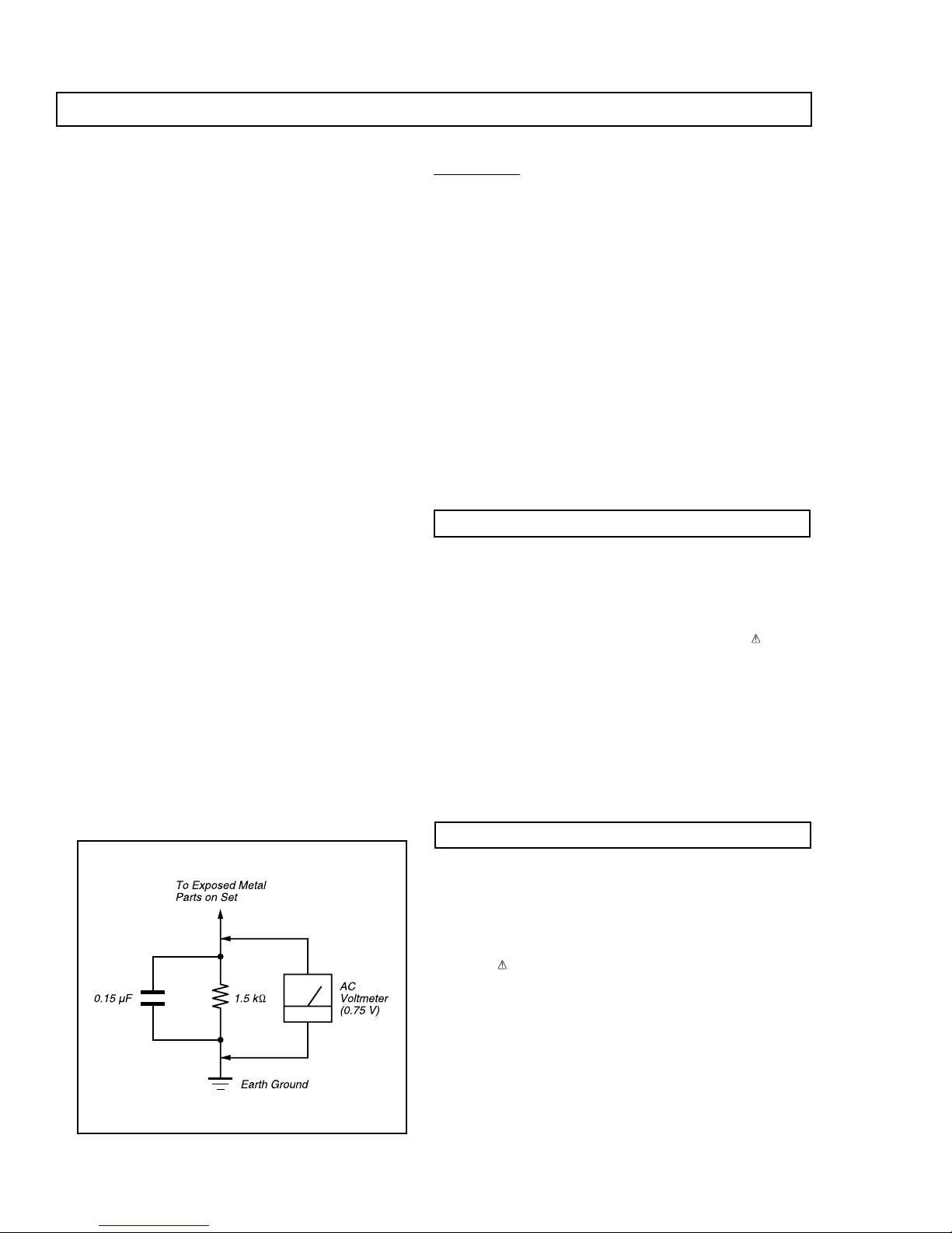
Leakage Test
The AC leakage from any exposed metal part to earth ground
and from all exposed metal parts to any exposed metal part
having a return to chassis, must not exceed 0.5 mA (500
microampere). Leakage current can be measured by any one
of three methods.
1. A commercial leakage tester, such as the Simpson 229 or
RCA WT-540A. Follow the manufacturers' instructions to use
these instructions.
2. A battery-operated AC milliammeter. The Data Precision
245 digital multimeter is suitable for this job.
3. Measuring the voltage drop across a resistor by means of
a VOM or battery-operated AC voltmeter. The "limit"
indication is 0.75 V, so analog meters must have an accurat e
low voltage scale. The Simpson's 250 and Sanwa SH-63T rd
are examples of passive VOMs that are suitable. Nearly
all battery operated digital multimeters that have a 2V AC
range are suitable. (See Figure A)
WARNING!!
NEVER TURN ON THE POWER IN A CONDITION IN WHICH THE
DEGAUSS COIL HAS BEEN REMOVED.
SAFETY-RELA TED COMPONENT W ARNING!!
COMPONENTS IDENTIFIED BY SHADING AND MARK ON THE
SCHEMA TIC DIAGRAMS, EXPLODED VIEWS AND IN THE PARTS
LIST ARE CRITICAL FOR SAFE OPERATION. REPLACE THESE
COMPONENTS WITH SONY PARTS WHOSE PART NUMBERS
APPEAR AS SHOWN IN THIS MANUAL OR IN SUPPLEMENTS
PUBLISHED BY SONY. CIRCUIT ADJUSTMENTS THAT ARE
CRITICAL FOR SAFE OPERATION ARE IDENTIFIED IN THIS
MANUAL. FOLLO W THESE PROCEDURES WHENEVER CRITICAL
COMPONENTS ARE REPLACED OR IMPROPER OPERATION IS
SUSPECTED.
Figure A
AVER TISSEMENT!!
NE JAMAIS METTRE SOUS TENSION QUAND LA BOBINE DE
DEMAGNETISA TION EST ENLEVEE.
ATTENTION AUX COMPOSANTS RELA TIFS A LA SECURITE!!
LES COMPOSANTS IDENTIFIES PAR UNE TRAME ET PAR UNE
MARQUE SUR LES SCHEMAS DE PRINCIPE, LES VUES
EXPLOSEES ET LES LISTES DE PIECES SONT D'UNE
IMPORTANCE CRITIQUE POUR LA SECURITE DU
FONCTIONNEMENT. NE LES REMPLACER QUE PAR DES
COMPOSANTS SONY DONT LE NUMERO DE PIECE EST
INDIQUE DANS LE PRESENT MANUEL OU DANS DES
SUPPLEMENTS PUBLIES PAR SONY. LES REGLAGES DE
CIRCUIT DONT L'IMPORTANCE EST CRITIQUE POUR LA
SECURITE DU FONCTIONNEMENT SONT IDENTIFIES DANS LE
PRESENT MANUEL. SUIVRE CES PROCEDURES LORS DE
CHAQUE REMPLACEMENT DE COMPOSANTS CRITIQUES, OU
LORSQU'UN MAUVAIS FONTIONNEMENT SUSPECTE.
— 4 —
CPD-E210
5
US
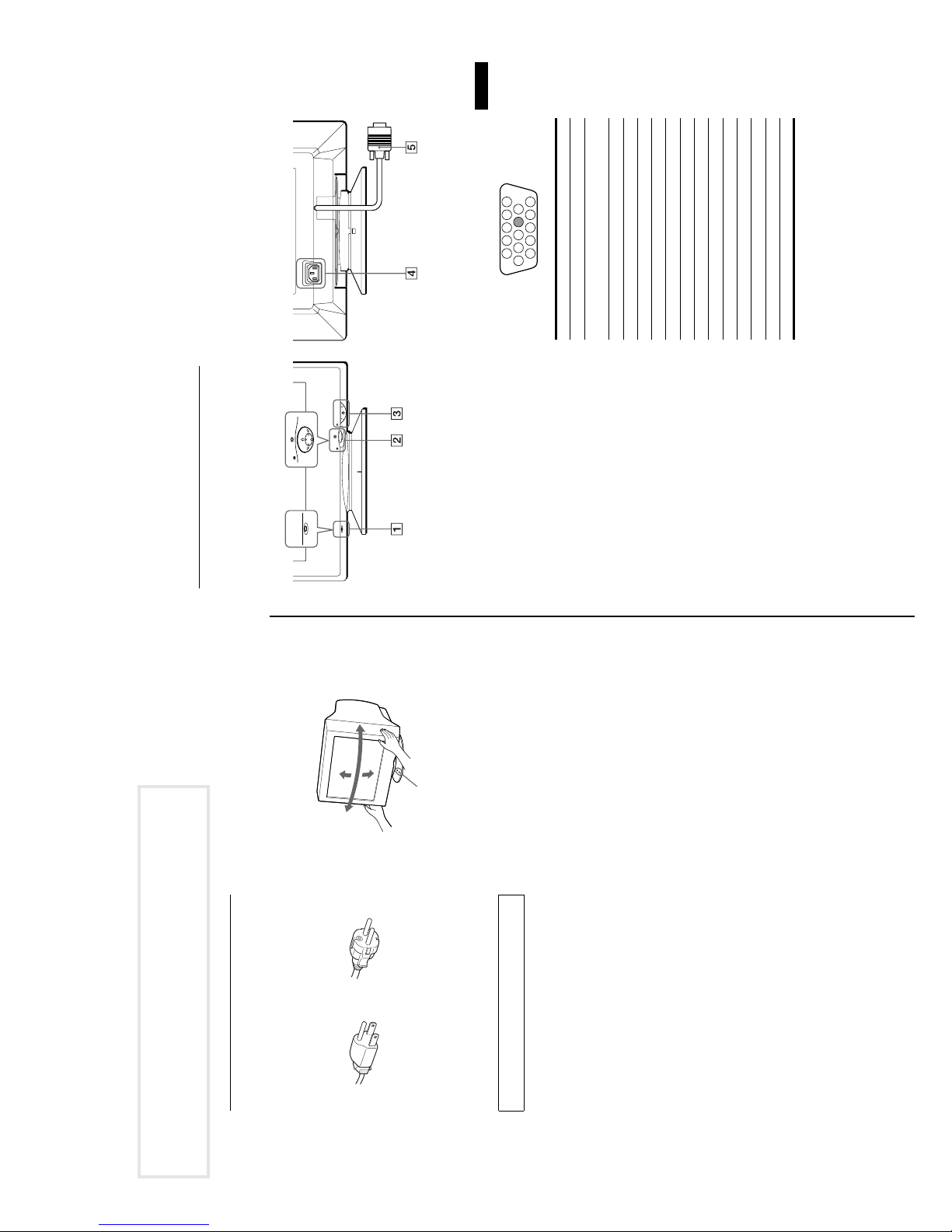
Identifying parts and controls
See the pages in parentheses for further details.
1
RESET button (page 12)
This button resets the adjustments to the factory settings.2Control button (page 9)
The control button is used to display the menu and make
adjustments to the monitor, including brightness and contrast
adjustments.
3 1
(power) switch and indicator (pages7, 13, 16)
This button turns the monitor on and off. The power indicator
lights up in green when the monitor is turned on, and either
flashes in green and orange, or lights up in orange when the
monitor is in power saving mode.
4
AC IN connector (page 6)
This connector provides AC power to the monitor.5Video input connector (HD15) (page 6)
This connector inputs RGB video signals (0.700 Vp-p,
positive) and sync signals.
* DDC (Display Data Channel) is a standard of VESA.
AC IN
MENU
RESET
MENU
RESET
RearFront
Pin No. Signal
1Red
2 Green
(Sync on Green)
3Blue
4 ID (Ground)
5 DDC Ground*
6 Red Ground
7 Green Ground
8 Blue Ground
9–
10 Ground
11 ID (Ground)
12 Bi-Directional Data (SDA)*
13 H. Sync
14 V. Sync
15 Data Clock (SCL)*
5
10
9
876
1 2 3 4
11 12 13 14 15
GENERAL
SECTION 1
90°
15°
5°
for 200 to 240 V AC
for 100 to 120 V AC
• Before disconnecting the power cord, wait at least 30 seconds
Centering dots
after turning off the power to allow the static electricity on the
screen’s surface to discharge.
(degaussed) for about 5 seconds. This generates a strong
• After the power is turned on, the screen is demagnetized
magnetic field around the screen which may affect data stored
on magnetic tapes and disks placed near the monitor. Be sure to
keep magnetic recording equipment, t a pes, and disks away
from the monitor.
The equipment should be installed near an ea sily accessible
outlet.
Installation
draperies, etc.) that may block the ventilation holes
subject to direct sunlight
Do not install the monitor in the following places:
• on surfaces (rugs, blankets, etc.) or near materials (curtains,
• near heat sources such as radiators or air ducts, or in a place
transformer or high voltage power lines
• in a place subject to severe temperature changes
• in a place subject to mechanical vibrati on or shock
• on an unstable surface
• near equipment which generates magnetism, such as a
• near or on an electrically charged metal surface
Maintenance
90°
Use of the tilt-swivel
This monitor can be adjusted within the angles shown below. To
find the center of the monitor’s turning radi us, alig n the center o f
the monitor’s screen with the centering dots on the stand.
Hold the monitor at the bottom with both hand s whe n yo u tu rn it
horizontally or vertically. Be careful not to pinch your fingers at
the back of the monitor when you tilt the monitor up vertically.
Precautions
Warning on power connections
• Use the supplied power cord. If you use a different power cord,
be sure that it is compatible with your local power supply.
For the customers in the U.S.A.
If you do not use the appropriate cord, this monitor will not
conform to mandatory FCC standards.
Example of plug types
liquid, do not use any type of cleaner containing an anti-static
solution or similar additive as this may scratch the screen’s
coating.
abrasive items such as a ballpoin t pen or screwdri ver. This type
of contact may result in a scratched picture tube.
moistened with a mild detergent solution. Do not use any type
of abrasive pad, scou ring po wder o r solve nt, such a s alc ohol or
• Clean the screen with a soft cloth. If you use a glass cleani ng
• Do not rub, touch, or tap the surface of the screen with sharp or
benzene.
• Clean the cabinet, panel and controls with a soft cloth lightly
Transportation
When you transport this monitor for repair or shipment, use the
original carton and packing materials.
4
The following are partial abstracts from the Operating Instruction
Manual. The page numbers shown reflect those of the Operating
Instruction Manual.
— 5 —

CPD-E210
MENU
OK
MENU
CONV
CENTER
COLOR
HELP
EXIT
GEOM
OPTION
SIZE
LANG
US
7
ITALIANO
LANGUAGE
FRANÇA I S
ENGL I SH
ESPAÑOL
SVENSKA
DEUTSCH
NEDERLANDS
to select a language.
M
/
m
Selecting the on-screen menu
Step 3:Turn on the monitor and
language (LANG)
English, French, German, Spanish, Italian, Dutch, Swedish,
computer
First turn on the monitor, then turn on the computer.
Russian and Japanese versions of the on-screen menus are
MENU
Press the center of the control button.
See page 9 for more information on using the control button.
available. The default setting is English.
1
video signal cable is properly connected and all plugs are firmly
The installation of your monitor is complete.
If necessary, use the monitor’s controls to adjust the picture.
seated in their sockets.
If no picture appears on your screen
• Check that the monitor is correct ly connected to the computer.
• If NO INPUT SIGNAL appears on the screen, confirm that the
MENU
Move the control button to highlight LANG and
press the center of the control button again.
2
screen, try pressing any ke y on the computer keyboard.
OF SCAN RANGE appears on the screen, reconnect the old
monitor. Then adjust the computer’s graphic board so t hat the
horizontal frequency is between 30 – 85 kHz, and the vertical
• If you are replacing an old monitor with this model and OUT
frequency is between 48 – 120 Hz.
For more information about the on-screen messages, see “Trouble
• If MONITOR IS IN POWER SAVE MODE appeared on the
Move the control button
• ENGLISH
• FRANÇAIS: French
• DEUTSCH: German
• ESPAÑOL: Spanish
• ITALIANO: Italian
• NEDERLANDS: Dutch
• SVENSKA: Swedish
• : Russian
3
symptoms and remedies” on page 14.
For customers using Windows 95/98
To maximize the potential of your monitor, install the new model
information file from the supplied Wind ows Monitor Information Disk
onto your PC.
This monitor complies with the “VESA DDC” Plug & Play standard. If
your PC/graphics board complies with DDC, select “Plug & Play Monitor
(VESA DDC)” or this monitor’s model name as the monit or type in the
• : Japanese
To close the menu
Press the center of the control button once to ret urn to the main MENU,
and twice to return to normal viewing. If no buttons are pressed, the menu
closes automatically after about 30 seconds.
To reset to English
Press the RESET button while the LANGUAGE menu is displayed on the
screen.
“Control Panel” of Windows 95/98. If your PC/graphics board has
difficulty communicating with this monitor, load the Windows Monitor
Information Disk and select this monitor’s model name as the monitor
type.
For customers using Windows NT4.0
Monitor setup in Windows NT4.0 is different from Wi ndows 95/98 and
does not involve the selection of mon itor type. Refer to the Windows
NT4.0 instruction manual for furthe r details on adjusting the resolution,
refresh rate, and number of colors.
Adjusting the monitor’s resolution and color number
Adjust the monitor’s resolution and color number by referring to your
computer’s instruction manual. The color number may vary according to
your computer or video board. The color palette setting and the actual
number of colors are as follows:
• High Color (16 bit) t 65,536 colors
• True Color (24 bit) t about 16.77 million colors
In true color mode (24 bit), speed may be slower.
Macintosh adapter (not supplied)
AC IN
computer
You will need a Macintosh adapter (not supplied).
x Connecting to a Macintosh or compatible
your computer
Setup
Before using your monitor, check that the following accessories
are included in your carton:
• Power cord (1)
• Windows Monitor Information Disk (1)
• Warranty card (1)
• Notes on cleaning the screen’s surface (1)
• This instructio n manual (1)
• Information sheet for Macintosh users (1)
Step 1:Connect your monitor to
Turn off the monitor and computer before connecting.
Note
Do not touch the pins of the video cable connector as this might bend the
pins.
to video
output
x Connecting to an IBM PC/AT or compatible
AC IN
Macintosh or
compatible computer
Step 2:Connect the power cord
With the monitor and computer switched off, first connect the
power cord to the monitor, then connect it to a power outlet.
AC IN
to video output
to AC IN
power cord (supplied)
to a power outlet
computer
IBM PC/AT or
compatible computer
6
— 6 —
CPD-E210
9
US
x Using the control button
1
Display the main MENU.
Press the center of the control button to display the main
MENU on your screen.
2
Select the menu you want to adjust.
Highlight the desired menu by moving the control button
towards the rear to go up (
M
), towards the front to go down
(
m
), and left (
<
) or right (
,
) to move sideways.
3
Adjust the menu.
Move the control button left (
<
) or right (
,
) to make the
adjustment.
4
Close the menu.
Press the center of the control button once to return to the
main MENU, and twice to return to normal viewing. If no
buttons are pressed, the menu closes automatically after about
30 seconds.
x Resetting the adjustments
Press the RESET button. See page 12 for more information on
resetting the adjustments.
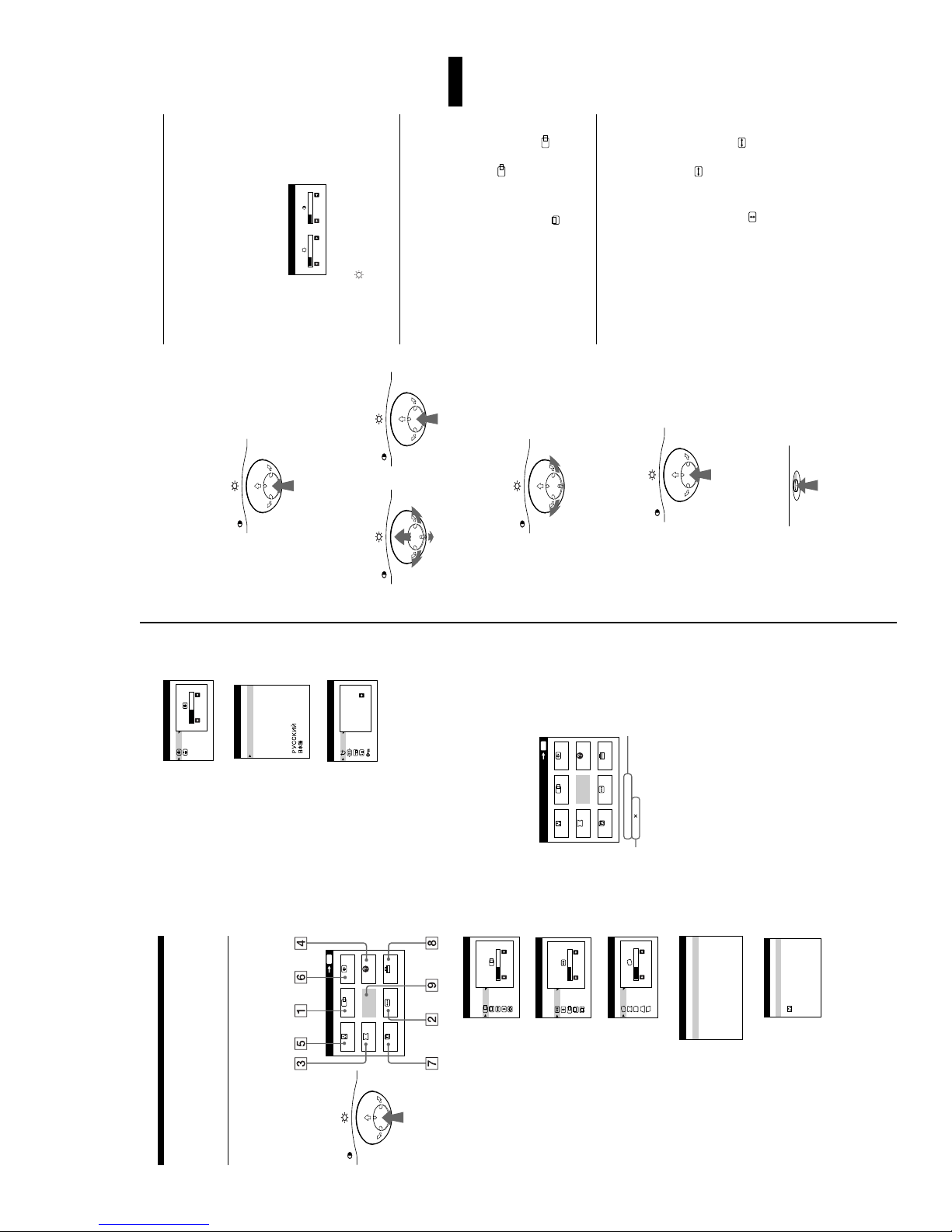
Adjusting the brightness and
contrast
Brightness and contrast adjustments are made using a separate
BRIGHTNESS/CONTRAST menu.
These settings are stored in memory for all input signals.
1
Move the control button in any direction.
The BRIGHTNESS/CONTRAST menu appears on the
screen.
2
Move the control button
m
/
M
to adjust the
brightness ( ), and
<
/
,
to adjust the contrast
(
6
).
The menu automatically disappears after about 3 seconds.
Adjusting the centering of the
picture (CENTER)
This setting is stored in memory for the current input signal.
1
Press the center of the control button.
The main MENU appears on the screen.2Move the control button to highlight CENTER
and press the center of the control button again.
The SIZE/CENTER menu appears on the screen.3First move the control button
m
/
M
to select for
horizontal adjustment, or for vertical adjustment.
Then move the control button
<
/
,
to adjust the
centering.
Adjusting the size of the picture
(SIZE)
This setting is stored in memory for the current input signal.
1
Press the center of the control button.
The main MENU appears on the screen.2Move the control button to highlight SIZE and
press the center of the control button again.
The SIZE/CENTER menu appears on the screen.3First move the control button
m
/
M
to select for
horizontal adjustment, or for vertical
adjustment. Then move the control button
<
/
,
to
adjust the size.
MENU
MENU MENU
REAR
FRONT
MENU
MENU
RESET
26 26
BRI GHTNESS / CONTRAST
FLI CKER
TH I N HOR I Z ON TA L L I NE
information about this
DI STORTED SHAPE
D I SCOLORAT I ON
OUT OF FOCUS
monitor.5COLOR (page 10)
9300K
5000K
COLOR
Select the COLOR menu to adjust
the picture’s color temperature. You
can use this to match the monitor’s
colors to a printed picture’s colors.
8
OPTION
SIZE
LANG
GEOMETRY
GEOM (page 10)
Select the GEOM menu to adjust the
3
the horizontal
and vertical
frequencies of
the current
input signal
768
68.7kHz / 85Hz
1024
nt
nal
esolution
the r
of the curre
input sig
26
picture’s rotation and shape.
HELP
HELP (page 12)
4
RETURN TO MA I N MENU
RECOMMENDED RESOL U T I ON
Select the HELP menu to
display helpful hints and
26
DEGAUSS
ON
The horizontal and vertical frequencies of the current input signal
are displayed in the main MENU. If the signal matches one of t his
26
zoom.
MENU
HELP
CONV
OK
EXIT
CENTER
GEOM
COLOR
MENU
monitor’s factory preset modes, the resolution is also displayed.
26
S I ZE / CENTER
SIZE (page 9)
Selects the SIZE menu to adjust the
picture’s size, centering or zoom.
2
ITALIANO
LANGUAGE
FRANÇA I S
ENGL I SH
ESPAÑOL
SVENSKA
DEUTSCH
LANG (page 7)
Select LANG to choose the on-
7
Navigating the menu
NEDERLANDS
screen menu’s language.
Press the center of the control button to display the main MENU
on your screen. See page 9 for more information on using the
control button.
OPT I ON
monitor’s options. The options
include:
• degaussing the screen
• adjusting the moire cancellation
HELP
CONV
EXIT
CENTER
GEOM
COLOR
level
OPTION
SIZE
LANG
OPTION (page 11)
Select OPTION to adjust the
8
MENU
OK
MENU
MENU
position
• changing the on-screen menu
• locking the controls9EXIT
Select EXIT to close the menu.
CENTER (page 9)
Use the control button to select one of the following menus.
1
x Displaying the current input signal
S I ZE / CENTER
Selects the CENTER menu to adjust
the picture’s centering, size or
CONVERGENCE
CONV (page 10)
Select the CONV menu to adjust the
picture’s horizontal and vertical
convergence.
6
Customizing Your Monitor
You can make numerous adjustments to your monitor using the
on-screen menu.
— 7 —
CPD-E210
Changing the menu’s position
Additional settings (OPTION)
US
11
, to select ON.
,
to select (CONTROL
M
/
to select (OSD H POSITION)
M
/
m
to shift the on-screen menu.
,
Change the menu’s position if it is blocking an image on the
screen.
You can manually degauss (demagnetize) the monitor, adjust the
/
To change the menu’s on-screen position, first move
the control button
for horizontal adjustment, or (OSD V POSITION) for
vertical adjustment. Then move the control button
<
Press the center of the control button.
The main MENU appears on the screen.2Move the control button to highlight OPTION and
moire cancellation level, change the menu position, and lock the
controls.
1
m
Locking the controls
To protect adjustment data by lockin g the controls, first
move the control button
press the center of the control button again.
The OPTION menu appears on the screen.3Move the control button
LOCK). Then move the control button
to select the desired
M
/
m
To cancel the control lock
Only the 1 (power) switch, EXIT, and (CONTROL LOCK)
of the OPTION menu will operate. If any other items are
selected, the mark appears on the screen.
adjustment item.
Adjust the selected item according to the following
instructions.
Repeat the procedure above and set (CONTROL LOCK) to OFF.
Degaussing the screen
The monitor is automatically demagnetized (degaussed) when the
power is turned on.
To manually degauss the monitor, first move the
to select (DEGAUSS). Then move
M
/
m
control button
.
,
the control button
until the moire
,
/
<
to select (MOIRE ADJUST).
M
/
m
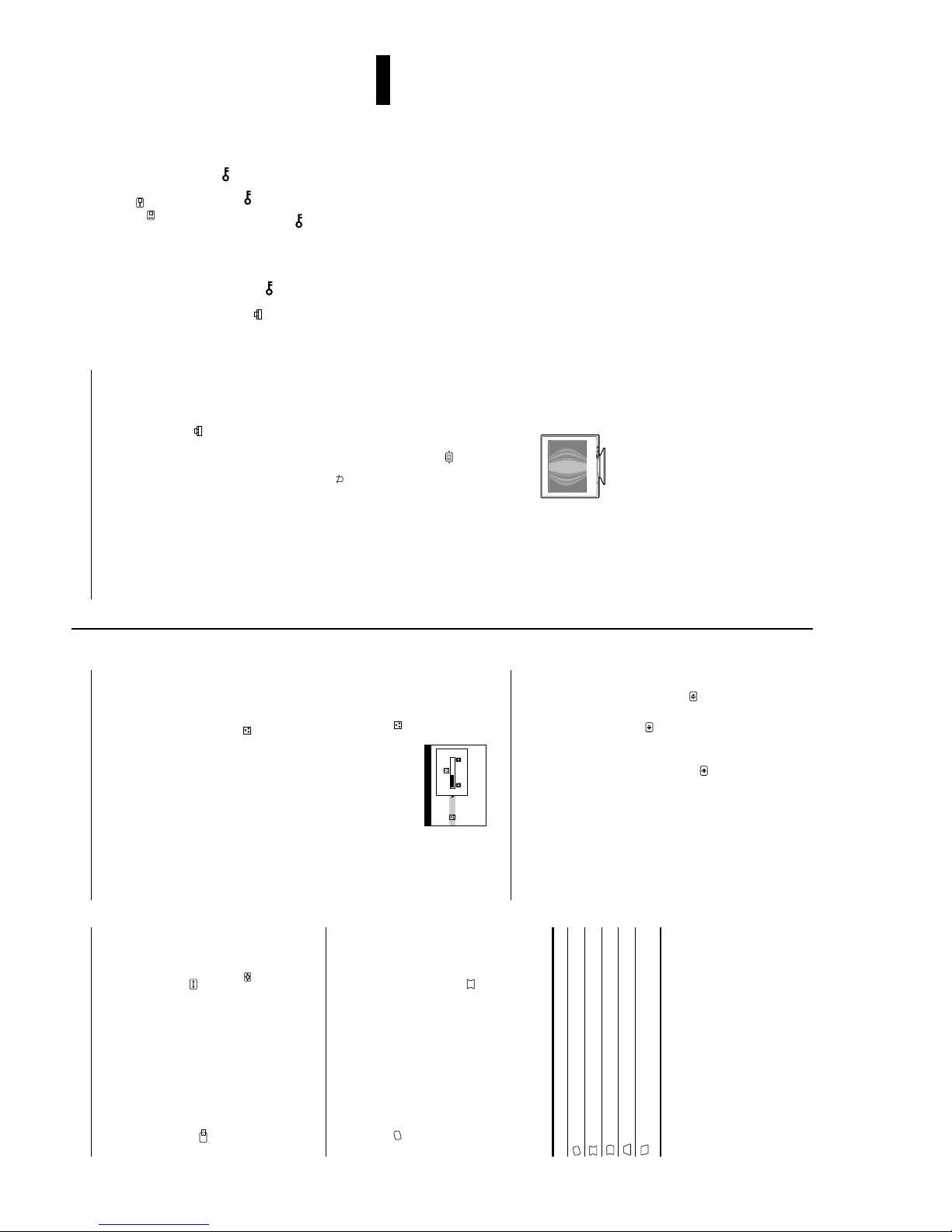
Example of moire
on your screen. It may appear due to interfere nce between the pattern
of the picture on the screen and the phosphor pitch pattern of the
The screen is deg a us se d for about 5 seconds . I f a s econd degauss
cycle is needed, allow a minimum interval of 20 minutes for the
best result.
Adjusting the moire*
If elliptical or wavy patterns appear on the screen, adjust the
moire cancellation level.
To adjust the amount of moire cancellation, first move
the control button
Then move the control button
effect is at a minimum.
monitor.
* Moire is a type of natural interference which produces soft, wavy lines
Adjusting the color of the picture
(COLOR)
Enlarging or reducing the picture
(ZOOM)
to
,
/
<
to select for
M
/
You can select your own color temperature between 9300K
and 5000K.
(GEOM)
The GEOM settings allow you to adjust the rotatio n and sh ape of
the picture.
to select . Then move
M
/
m
to adjust the color temperature.
,
/
<
First move the control button
the control button
The (rotation ) setting is stored in memory for all in put signals.
All other settings are stored in memory for the current input
26
9300K
5000K
COLOR
Press the center of the control button.
Adjusting the convergence (CONV)
The CONV settings allow you to adjust the quality of the picture
by controlling the convergence. The convergence refers to the
alignment of the red, green, and blue color signal s.
If you see red or blue shadows around letters or lines, adjust the
to select the
M
/
m
to make the adjustment.
,
/
rotate the picture
<
Press the center of the control button.
The main MENU appears on the screen.2Move the control button to highlight GEOM and
press the center of the control button again.
The GEOMETRY menu appears on the screen.3First move the control button
desired adjustment item. Then move the control
button
signal.
1
Select To
The main MENU appears on the screen.2Move the control button to highlight CONV and
convergence.
These settings are stored in memory for all input signals.
1
expand or contract the pi c ture sides
shift the picture sides to the left or right
adjust the picture width at the top of the screen
shift the picture to the left or right at the top of the
to select a color
M
/
m
Press the center of the control button.
The main MENU appears on the screen.2Move the control button to highlight COLOR and
press the center of the control button again.
The COLOR menu appears on the screen.3Move the control button
temperature.
The preset color temperatures are 5000K an d 9300K. Since
the default setting is 9300K, the whites will change from a
bluish hue to a reddish hue as the temperature is lowered to
The COLOR settings allow you to adjust the picture’s color
temperature by changing the color level of the white color field.
Colors appear reddish if the temperature is low, and bluish if the
temperature is high. This adjustment is useful for matching the
monitor’s colors to a printed picture’s colors.
This setting is stored in memory for all input signals.
1
to select (zoom),
M
/
m
to enlarge or reduce the picture.
,
/
<
CENTER and press the center of the control
Press the center of the control button.
The main MENU appears on the screen.2Move the control button to highlight SIZE or
button again.
The SIZE/CENTER menu appears on the screen.3Move the control button
and move
This setting is stored in memory for the current input signal.
1
maximum or minimum value.
Notes
• Adjustment stops when either the horizontal or vertical size reaches its
5000K.4If necessary, fine tune the color temperature.
• The horizontal adjustment value is not displaye d in the menu.
Adjusting the shape of the picture
press the center of the control button again.
screen
m
The CONVERGENCE menu appears on the screen.3First move the control button
horizontal adjustment, or for vertical
adjust the convergence.
adjustment. Then move the control button
10
— 8 —
US
Input signal
condition
CPD-E210
13
Troubleshooting
Before contacting technical support, refer to this section.
If thin lines appear on your screen
(damper wires)
The lines you are experiencing on your screen are normal for the
Trinitron monitor and are not a malfunction. These are shadows
from the damper wires used to stabilize the aperture grille and are
most noticeable when the screen’s background is light (usually
white). The aperture grille is the essential element that makes a
Trinitron picture tube unique by a llo wi ng m ore lig ht to reach the
(See Appendix for a list of the factory preset modes.)
Technical Features
Preset and user modes
When the monitor receives an input signal, it automatically
matches the signal to one of the factory preset modes stored in the
monitor’s memory to provide a high quality picture at the center of
the screen.
For input signals that do not match one of the factory preset modes,
the digital Multiscan technology of this monitor ensures that a
clear picture appears on the screen for any timing in the monitor’s
frequency range (horizontal: 30 – 85 kHz, vertical: 48 – 120 Hz).
If the picture is adjusted, the adjustment data is stored as a user
to jump directly to the
,
screen, resulting in a brighter, more detailed picture.
mode and automatically recalled whenever the same input signal
is received.
Damper wires
OUT OF SCAN RANGE
INFORMATION
On-screen messages
If no picture appears on the screen, one of the following messages
appears on the screen. To solve the problem, see “Trouble
symptoms and remedies” on page 14.
.
TAR, and NUTEK. If the monitor is connected to a
S
NERGY
computer or video graphics board that is DPMS (Display Power
Management Signaling) compliant, the monitor will automatically
Note for Windows users
For Windows users, check your vide o boa rd man ual or the utility
program which comes with your graphic board and select the
highest available refresh rate to maximize monitor performance.
Power saving function
reduce power consumption in three stages as shown below
This monitor meets the power-saving guidelines set by VESA,
E
(power)
1
indicator
Power mode Power consumption
120 W green
≤
normal
The input signal condition
OUT OF SCAN RANGE
indicates that the input signal is not supported by the monitor’s
specifications.
NO INPUT SIGNAL
indicates that no signal is input.
MONITOR IS IN POWER SAVE MODE
indicates that the computer is in power saving mode. This
message is displayed only when your computer is in a power
saving mode and you press an y one of th e buttons on the monito r.
alternate
alternate
15 W green and orange
15 W green and orange
≤
1 standby
operation
3 W orange
≤
≤
Environmental Protection Agency.
2 suspend
power off 0 W off
(sleep)*
3 active off**
(deep sleep)*
* “Sleep” and “de ep sleep” are power saving modes defined by the
** When your computer is in a power saving mode, MONITOR IS IN
(CONTROL LOCK)
cord from the power outlet.
POWER SAVE MODE appears on the screen if you press any button
on the monitor. After a few seconds, the monitor enters the power
saving mode again.
∗∗∗ Power consumption of 0 W is acheivable by disconnecting the power
RESET
to jump directly to the CONVERGENCE
,
OUT OF FOCUS
The picture may seem to be out of focus when the red and blue
color signals are not aligned properly, causing red or blue
shadows to appear around letters and lines. Try adjusting the
picture’s convergence to make the shadows disappear. Move the
control button
menu. When the CONVERGNECE menu is displayed, the
contrast, brightness and moire ad justment settings are
automatically reset for all input signals.
DISCOLORATION
If the picture’s color appears abnormal in certain areas of the
screen, first check for any loose signal cables. After you have
checked the cables, try degaussing (demagnetizing) the screen
Press the center of the control button.
Helpful hints and information
(HELP)
The HELP menu contains helpful h ints and inform ation about thi s
monitor. If your monitor is displaying symptoms that match those
listed in the HELP menu, follow the on-screen instructions to
resolve the problem. If the symptoms do not matc h those listed in
The main MENU appears on the screen.2Move the control button to highlight HELP and
the HELP menu or if the problem persists, see “Trouble
symptoms and remedies” on page 14.
1
OPTION menu, then select (DEGAUSS).
manually. Move the control button
Resetting the adjustments
RETURN TO MA I N MENU
RECOMMENDED RESOL U T I ON
HELP
press the center of the control button again.
The following HELP menu appears on the screen.
This monitor has the following three reset methods. Use the
RESET button to reset the adjustments.
FLI CKER
TH I N HOR I Z ON TA L L I NE
DI STORTED SHAPE
D I SCOLORAT I ON
OUT OF FOCUS
to select a HELP menu
M
/
m
Move the control button
3
item and press the center of the control button
again.
Instructions or information to resolv e the pro blem appears on
Resetting a single adjustment item
Use the control button to select the adjustment item you want to
reset, and press the RESET button.
the screen. An explanation of each menu item is given below.
RECOMMENDED RESOLUTION
If the picture does not fill the screen to th e edge s o r if th e pi ctu re
Resetting all of the adjustment data for the
current input signal
Press the RESET button when no men u is displayed on the screen.
Note that the following items are not reset by this method:
• on-screen menu language (page 7)
• on-screen menu position (page 11)
• control lock (page 11)
Resetting all of the adjustment data for all input
signals
Press and hold the RESET button for more than two seconds.
Note
The RESET button does not function when
is set to ON.
to
,
1024X768 AT 85Hz USING PC.
1280X1024 AT 75Hz.
SET RESOLUT I ON TO
CURRENT SE TT I NG I S
RECOMMENDED RESOL UT ION
appears too large for the screen, adjust the resolution to the fig ures
shown in the menu using your computer. If the input signal
matches one of this monitor’s factory preset modes, the resolution
and refresh rate of the current input signal are displayed.
FLICKER
If the picture is flickering, adjust the refresh rate to figures shown
in the menu. If the input signal matches one of this monitor’s
factory preset modes, the refresh rate of the current input signal is
75Hz OR 85Hz USING PC.
FLI CKER
SET REFRESH RATE TO
CURRENT SE TT I NG I S 6 0H z .
displayed.
THIN HORIZONTAL LINE
The lines that appear on your screen are damper wires. See
page 13 for more information about the damper wires.
DISTORTED SHAPE
If the shape of the picture on the screen seems distorted, try
adjusting the picture’s geometry. Move the co ntrol bu tton
jump directly to the GEOMETRY menu.
12
— 9 —
CPD-E210
15
US
* If a second dega uss cycle is needed, allow a minimum interval of 20 mi nut es for the best result. A humming noise may be heard, but this is not a
malfunction.
Displaying this monitor’s name, serial number,
and date of manufacture.
While the monitor is receiving a video signal, press and hold the
center of the control button for more than five seconds to display
this monitor’s information box.
If the problem persists, call your authorized Sony dealer and give
the following information.
• Model name: CPD-E200
• Serial number
• Name and specifications of your computer and graphics board.
Picture is ghosting
• Eliminate the use of video cable extensions and/or video switch boxes.
• Check that all plugs are firmly seated in t heir sockets.
Picture is not centered or sized
properly
• Adjust the size (page 9) or centering (page 9). Note that some video modes do not fill the
screen to the edges.
Edges of the image are curved
• Adjust the geometry (page 10).
Wavy or elliptical pattern (moire)
is visible
• Select MOIRE ADJUST and adjust the moire cancellation effect (page 11).
x
Problems caused by the connected compute r or other equipment
• Change your desktop pattern.
Color is not uniform
• Degauss the monitor* (page 11). If you place equipment that generates a magnetic field,
such as a speaker, near the monitor , or if you chang e the direction th e monitor fa ces, color
may lose uniformity.
White does not look white
• Adjust the color temperatu r e (page 10).
Letters and lines show red or blue
shadows at the edges
• Adjust the convergence (page 10).
Monitor buttons do not operate
• If the control lock is set to ON, set it to OFF (page 11).
A hum is heard right after the
power is turned on
• This is the sound of the auto-degauss cycle. W hen the power is turned on, the monitor is
automatically degaussed for five seconds.
Symptom Check these items
MENU
MODEL : CPD - E 20 0
SER NO:1234567
MANUFACTURED: 1 9 9
INFORMATION
9-52
Example
b
to the left or right.
°
their sockets (page 6).
Problems caused by the connected computer or other equipment
• Check that the 1 (power) switch is in the “on” position.
• Check that the video signa l cable is properly connected and all plugs are firmly seated in
• Check that the HD15 video input connector’s pins are not bent or pushed in.
Problems caused by the connected computer or other equipment
x
• Check that the computer’s power is “on.”
• Check that the graphic board is completely seated in the proper bus slot.
x
• The computer is in power saving mo de. Try pressing any key on the computer keyboard.
• Check that the computer’s power is “on.”
• Check that the graphic board is completely seated in the proper bus slot.
replaced an old monitor with this monitor, reconnect the old monitor and adjust the
frequency range to the following.
Problems caused by the connected computer or other equipment
x
• Check that the video frequency range is within that specified for the monitor. If you
Horizontal: 30 – 85 kHz
V e rtic a l: 48 – 120 H z
• Use the Self-diagnosis function (page 16).
following. Install the Win dows Monitor Information Disk (page 7) and select this monitor
(“CPD-E200”) from among the Sony monitors in the Windows 95/98 monitor selection
screen.
connected (page 6).
monitors, laser printers, electric fans, fluorescent lighting, or televisions.
• Isolate and eliminate any potential sources of electric or magnetic fields such as other
• Move the monitor away from power lines or place a magnetic shield near the monitor.
• Try plugging the monitor into a different AC outlet, preferably on a different circuit.
• Try turning the monitor 90
the input signal are supported by this monitor (Appendix). Even if the freq uen cy is within
the proper range, some video boards may have a sync pulse that is too narrow for the
Problems caused by the connected computer or other equipment
x
monitor to sync correctly.
• Check your graphics board manual for the proper monitor setting.
• Confirm that the graphics mode (VESA, Macintosh 16" Color, etc.) and the frequency of
• Adjust the computer’s refresh rate (vertical frequenc y) to obta in the be st possible pict ure.
• Adjust the brigh tness and contrast (page 9).
• Degauss the monitor* (page 11).
• Select MOIRE ADJUST and adjust the moire cancellation effect (page 11).
If the 1 (power) indicator is not lit • Check that the power cord is properly connected.
If the NO INPUT SIGNAL message
appears on the screen, or if the 1
(power) indicator is either orange or
alternating between green and
orange
If the MONITOR IS IN POWER
SAVE MODE message appeared on
the screen, or if the 1 (power)
indicator is either orange or
alternating between green and
Symptom Check these items
Trouble symptoms and remedies
If the problem is caused by the connected compu ter or other equipment, please refer to the connected equipment’s instruction manual.
No picture
Use the self-diagnosis function (page16) if the following recommendations do not resolve the problem.
orange
If the OUT OF SCAN RANGE
message appears on the screen
If no message is displayed and the 1
(power) indicator is green or flashing
orange
If using Windows 95/98 • If you replaced an old monitor with this monitor, reconnect the old monitor and do the
If using a Macintosh system • Check that the Macintosh adapter (not supplied) and the video signal cable are properly
Picture flickers, bounces,
oscillates, or is scrambled
Picture is fuzzy
14
— 10 —

CPD-E210
Specifications
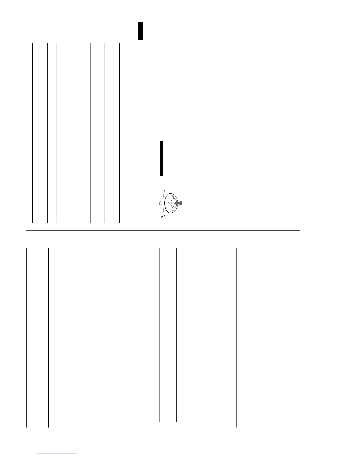
Self-diagnosis function
This monitor is equipped with a self-diagnosis fun ction. If there is
inches)
8
419.5 mm (w/h/
/
×
5
16
Vertical: 48 to 120 Hz
AC input voltage/current 100 to 240 V, 50 – 60 Hz, Max. 1.7 A
Disconnect the video input cable or turn off the
1
Power consumption 120 W
connected computer.2Press the
×
413.5
8
/
×
3
16
×
(16
d)
Approx. 404
Mass Approx. 20 kg (44 lb 1 oz)
Dimensions
(power) button twice to turn the monitor
1
off and then on.
• Horizontal sync width should be more than 1.0 µsec.
Supplied accessories See page 6
for 2 seconds before the
,
Move the control button
monitor enters power saving mode.
* Recommended horizontal and vertical timing condition
MENU
• Horizontal blanking width should be more than 3.0 µsec.
Plug and Play DDC1/DDC2B/DDC2Bi
3
• Vertical blanking width should be more than 500 µsec.
Design and specifications are subject to change without notice.
(power) button twice to turn the monitor off
1
(power) indicator is flashing orange
1
If all four color bars appear (white, red, green, blue), the monitor
is working properly. Reconnect the video input cable and check
the condition of your compute r .
If the color bars do not appear, there is a potentia l monitor failure.
Inform your authorized Sony dealer of the monitor’s condition.
If the
Press the
and then on.
If the 1 (power) indicator lights up green , the monitor is wo rking
properly.
If the 1 (power) indicator is still flashing, there is a potential
monitor failure. Count the number of seconds between orange
flashes of the 1 (power) indicator and inform your authorized
Sony dealer of the monitor’s conditio n. Be sure to n ote the m odel
name and serial number of your monitor. Also note the make and
model of your computer an d video board.
16
243 mm (w/h)
inches)
8
×
/
5
9
×
4
/
3
17 inches measured diagonally
90-degree deflection
FD Trinitron
(14
16.0" viewing image
CRT 0.24 mm a perture grille pitch (cent er)
Viewable image size Approx. 327
Resolution
MENU
RESET
a problem with your monitor or computer, the screen will go
blank and the 1 (power) indicator will either light up green or
flash orange. If the 1 (power) indicator is lit in orange, the
computer is in power saving mode. Try pressing any key on the
keyboard.
234 mm (w/h)
inches)
4
×
/
1
9
×
8
/
3
Vertical: 1200 lines
Vertical: 768 lines
(12
Maximum Horizontal: 1600 dots
Recommended Horizontal: 1024 dots
Standard image area Approx. 312
Deflection frequency* Horizontal: 30 to 85 kHz
(power) indicator
1
(power) indicator is green
1
If the
— 11 —
CPD-E210
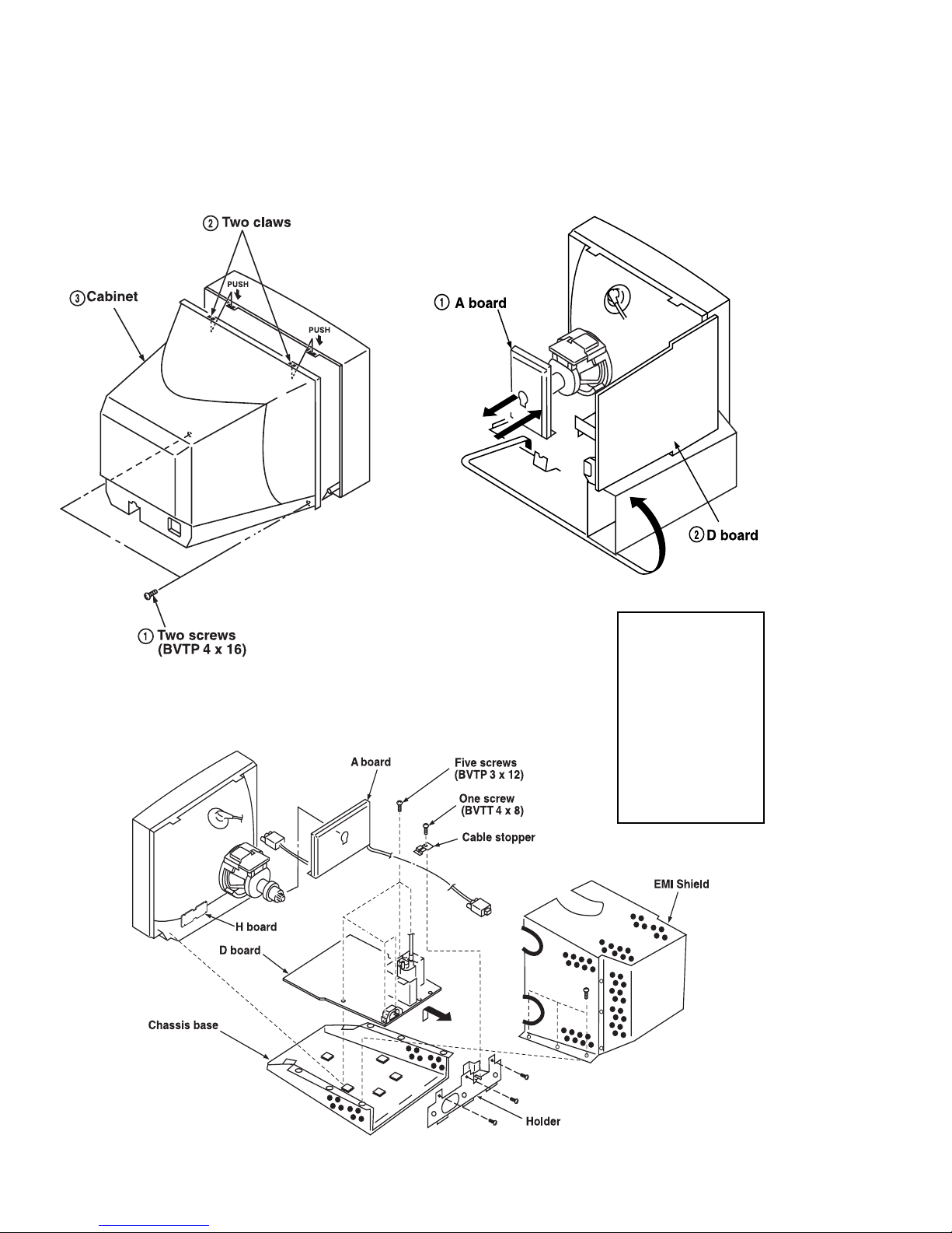
SECTION 2
DISASSEMBLY
2-1. CABINET REMOVAL 2-2. SERVICE POSITION
2-3. A, D & H BOARD REMOVAL
1 When the D board is
placed in service
position, the Safety Earth
Wire (green and yellow
wire) is disconnected.
2 After service is
completed and the
D-board reinstalled, the
Safety Earth Wire must
be reattached to the
chassis with the proper
screw. This must be
confirmed before any
subsequent procedures
are attempted.
— 12 —
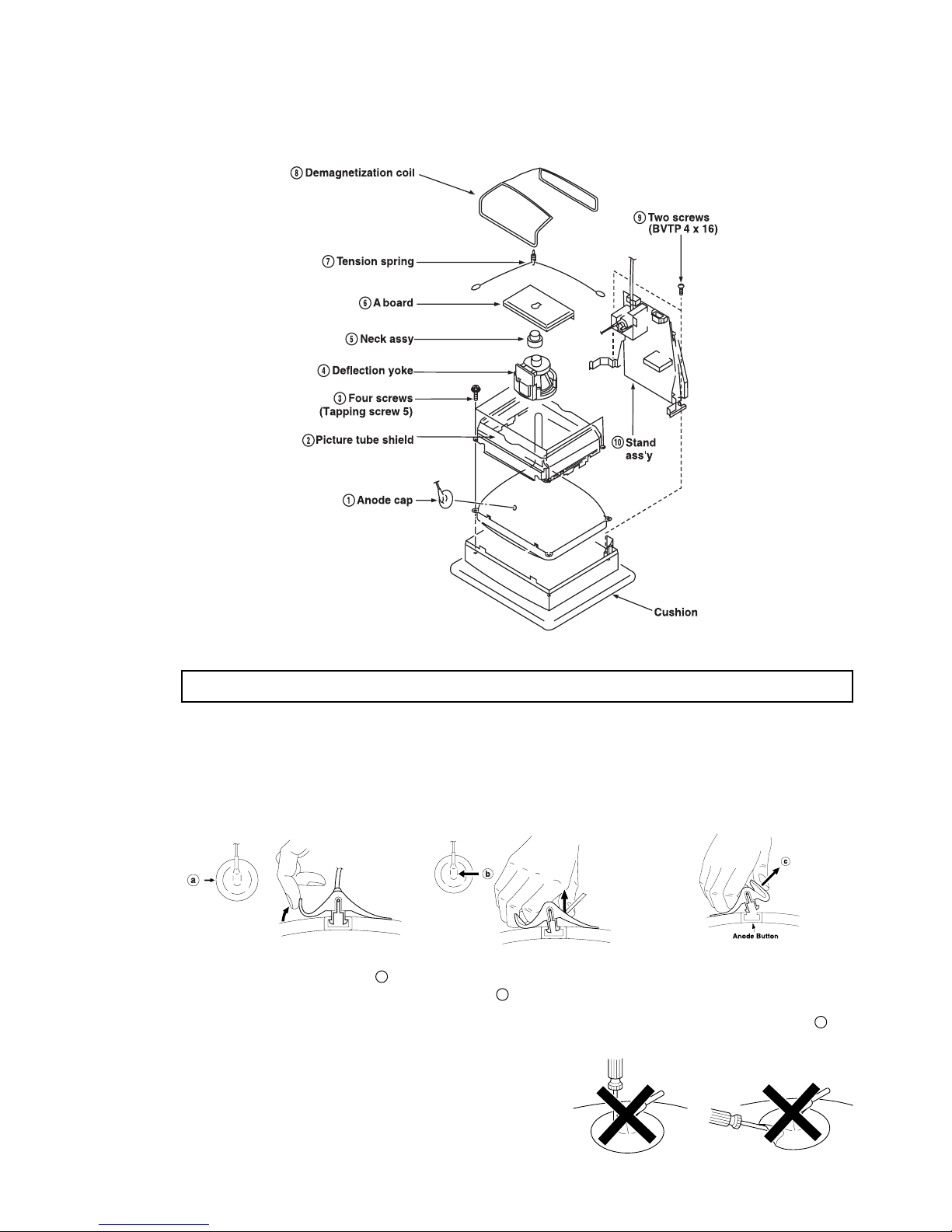
2-4. PICTURE TUBE REMOVAL
CPD-E210
ANODE CAP REMOVAL
WARNING: High voltage remains in the CR T e v en after the power is disconnected. To avoid electric shock, discharge CRT
NOTE: After removing the anode, short circuit the anode of the picture tube and the anode cap to either the metal
before attempting to remove the anode cap. Short between anode and CRT coated earth ground strap.
chassis, CRT shield, or carbon painted on the CRT.
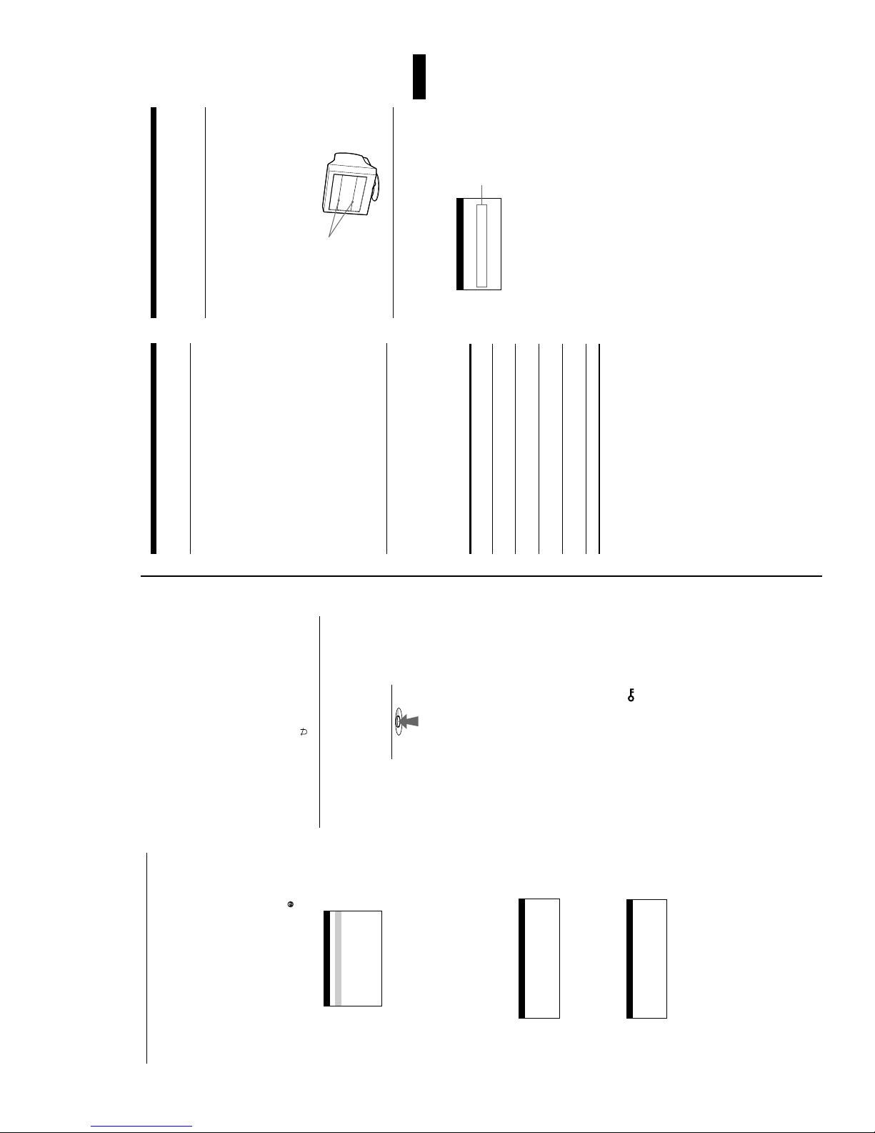
REMOVAL PROCEDURES
1 Turn up one side of the rubber cap in
the direction indicated by arrow a .
HOW TO HANDLE AN ANODE CAP
1 Do not use sharp objects which may cause damage to the
surface of the anode cap.
2 Do not squeeze the rubber covering too hard to avoid damag-
ing the anode cap. A material fitting called a shatter-hook terminal is built into the rubber.
3 Do not force turn the foot of the rubber cover. This may cause
the shatter-hook terminal to protrude and damage the rubber.
2 Use your thumb to pull the rubber
cap firmly in the direction indicated
by arrow b .
— 13 —
3 When one side of the rubber cap
separates from the anode button,
the anode cap can be removed by
turning the rubber cap and pulling
it in the direction of arrow c .
CPD-E210
SECTION 3
SAFETY RELATED ADJUSTMENTS
When replacing parts shown in the table below, the
following operational checks must be performed as a
safety precaution against X-ray emissions from the unit.
Part Replaced ( )
HV ADJ
HV Regulator
Circuit
HV HOLD
DOWN Circuit
Beam Current
Protector Circuit
Allow the unit to warm up for one minute prior to checking
the following conditions:
D board T501, IC501, RV501, R540,
D board T501, R510, R543, R547, R549,
D board T501, R545, R546, R548, R550,
RV501
Part Replaced ( )
R541, R542, R544, R564, R567,
R568, C532, C534, C539, C553,
C554, C555, C556, C558, C561
R552, R595, D515, D517, C540,
C542, C544, IC607, IC901
R596, R934, C535, C541,
IC605, IC607, IC901
a) HV Regulator Check
1) Input white cross hatch signal. (fH = 80 kHz)
2) CONT maximum and BRT center
3) Cut off Screen VR (G2).
4) Input voltage: 120 ± 2 V AC.
5) Confirm that the voltage is within the voltag e ran ge
shown below.
Standard voltage: 26.9 KV ± 0.4 KV
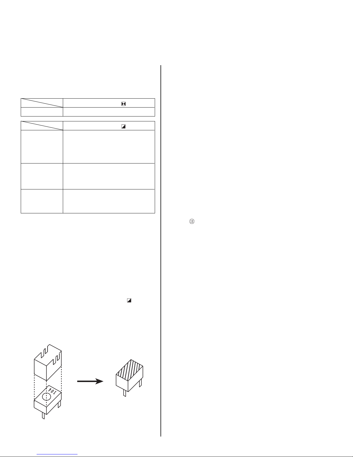
6) When replacing components identified by
sure to recheck the High Voltage.
7) V erify the High Voltage as shown above (26.9 KV ± 0.4 KV)
is within specification. If not, adjust R V501 on
D board.
, make
8) After adjusting the High V oltag e within specification,
put the R V cover on R V501 as shown in Figure 1 and apply
sufficient amount of R TV around RV501.
b) HV Protector Circuit Check
1) Confirm that the voltage between cathode of D517 and
GND is more than 27.5 VDC.
2) Using an external DC Power supply, apply the voltage
shown below between cathode of D517 on "D" and GND,
and confirm that the HV Hold-Down circuit works. (Raster
disappears) Apply DC Voltage: Less than 35.5 VDC.
Check Condition
• Input voltage: 100-120 V AC
• Input signal: (fH =80 kHz), White Cross Hatch
• Controls: CONT (max) & BR T (center)
c) Beam Protector Check (Software logic)
1) Using an external current source, apply < 1.55mA between
of FBT (T501) and GND, and confirm that the
pin
raster fades out.
Check Condition
• Input voltage: 100-120 V AC
• Input signal : (fH = 80 kHz), White Cross Hatch
• Controls: CONT (max) & BR T (center)
d) B+ V oltage Check
1) Input white cross hatch (fH = 80 kHz) signal.
2) CONT (max) & BRT (center).
3) Input voltage: 100-120 VAC.
Note: Use NF power supply or make sure that
distortion factor is 3% or less.
4) Confirm that the voltage is within the voltage
range shown below.
Standard voltage: 180 ± 3.0 VDC
Figure 1
RV501
— 14 —
 Loading...