

Page 1
3-864-132-41 (1)
Trinitron Color
Computer Display
Operating Instructions
Mode d’emploi
Bedienungsanleitung
Manual de instrucciones
Instruzioni per l’uso
GB
FR
DE
ES
IT
CPD-520GST
© 1998 by Sony Corporation
Page 2
Owner’s Record
The model and serial numbers are located at the rear of the unit.
Record the serial number in the space provided below. Refer to
these numbers whenever you call upon your dealer regarding this
product.
Model No. Serial No.
WARNING
To prevent fire or shock hazard, do not expose
the unit to rain or moisture.
Dangerously high voltages are present inside
the unit. Do not open the cabinet. Refer servicing
to qualified personnel only.
FCC Notice
This equipment has been tested and found to comply with the
limits for a Class B digital device, pursuant to Part 15 of the FCC
Rules. These limits are designed to provide reasonable protection
against harmful interference in a residential installation. This
equipment generates, uses, and can radiate radio frequency energy
and, if not installed and used in accordance with the instructions,
may cause harmful interference to radio communications.
However, there is no guarantee that interference will not occur in a
particular installation. If this equipment does cause harmful
interference to radio or television reception, which can be
determined by turning the equipment off and on, the user is
encouraged to try to correct the interference by one or more of the
following measures:
– Reorient or relocate the receiving antenna.
– Increase the separation between the equipment and receiver.
– Connect the equipment into an outlet on a circuit different from that
to which the receiver is connected.
– Consult the dealer or an experienced radio/TV technician for help.
You are cautioned that any changes or modifications not expressly
approved in this manual could void your authority to operate this
equipment.
Hinweise
• Aus ergonomischen Gründen wird empfohlen, die
Grundfarbe Blau nicht auf dunklem Untergrund zu
verwenden (schlechte Erkennbarkeit, Augenbelastung bei zu
geringem Zeichenkontrast).
• Aus ergonomischen Gründen (flimmern) sollten nur
Darstellungen bei Vertikalfrequenzen ab 70 Hz (ohne
Zeilensprung) verwendet werden.
• Die Konvergenz des Bildes kann sich auf Grund des
Magnetfeldes am Ort der Aufstellung aus der korrekten
Grundeinstellung verändern. Zur Korrektur empfiehlt es sich
deshalb, die Regler an der Frontseite für Konvergenz so
einzustellen, daß die getrennt sichtbaren Farblinien für Rot,
Grün und Blau bei z.B. der Darstellung eines Buchstabens zur
Deckung (Konvergenz) gelangen.
Siehe hierzu auch die Erklärungen zu Konvergenz.
NOTICE
This notice is applicable for USA/Canada only.
If shipped to USA/Canada, install only a UL LISTED/CSA
LABELLED power supply cord meeting the following
specifications:
SPECIFICATIONS
Plug Type Nema-Plug 5-15p
Cord Type SVT or SJT, minimum 3 × 18 AWG
Length Maximum 15 feet
Rating Minimum 7 A, 125 V
NOTICE
Cette notice s’applique aux Etats-Unis et au Canada
uniquement.
Si cet appareil est exporté aux Etats-Unis ou au Canada,
utiliser le cordon d’alimentation portant la mention UL
LISTED/CSA LABELLED et remplissant les conditions
suivantes:
SPECIFICATIONS
Type de fiche Fiche Nema 5-15 broches
Cordon Type SVT ou SJT, minimum 3 × 18 AWG
Longueur Maximum 15 pieds
Tension Minimum 7 A, 125 V
INFORMATION
This product complies with Swedish National Council for
Metrology (MPR) standards issued in December 1990 (MPR II) for
very low frequency (VLF) and extremely low frequency (ELF).
INFORMATION
Ce produit est conforme aux normes du Swedish National Council
for Metrology de décembre 1990 (MPR II) en ce qui concerne les
fréquences très basses (VLF) et extrêmement basses (ELF).
Hinweis
Dieses Gerät erfüllt bezüglich tieffrequenter (very low frequency)
und tiefstfrequenter (extremely low frequency) Strahlung die
Vorschriften des „Swedish National Council for Metrology (MPR)“
vom Dezember 1990 (MPR II).
INFORMACIÓN
Este producto cumple las normas del Consejo Nacional Sueco para
Metrología (MPR) emitidas en diciembre de 1990 (MPR II) para
frecuencias muy bajas (VLF) y frecuencias extremadamente bajas
(ELF).
Dieses Garät entspricht den folgenden europäischen EMVVorschriften für Betrieb in Wohngebieten, gewerblicher Gebleten
und Leichtindustriegebieten.
EN55022/1994 Klasse B
EN50082-1/1992
EN61000-3-2/1995
As an ENERGY STAR Partner, Sony
Corporation has determined that this
product meets the ENERGY STAR
guidelines for energy efficiency.
This monitor complies with the
TCO‘95 guidelines.
2
Page 3

Getting Started
TABLE OF CONTENTS
Getting Started
Precautions ........................................................................................................................... 4
Identifying Parts and Controls .......................................................................................... 5
Setup ...................................................................................................................................... 6
Automatically Adjusting the Size and Centering of the Picture................................... 7
Selecting the On-screen Display Language ..................................................................... 7
Selecting the Input Signal ................................................................................................... 8
Customizing Your Monitor
Adjusting the Picture Brightness and Contrast ............................................................... 9
Introducing the On-screen Display System ..................................................................... 9
Using the CENTER On-screen Display .......................................................................... 10
Using the SIZE On-screen Display .................................................................................. 10
Using the GEOM (Geometry) On-screen Display......................................................... 11
Using the ZOOM On-screen Display .............................................................................. 12
Using the COLOR On-screen Display ............................................................................ 12
Using the SCREEN On-screen Display........................................................................... 13
Using the OPTION On-screen Display........................................................................... 15
Using the LANG (Language) On-screen Display ......................................................... 17
Resetting the Adjustments ............................................................................................... 17
GB
FR
Technical Features
Preset and User Modes ..................................................................................................... 18
Power Saving Function ..................................................................................................... 19
Displaying the Monitor’s Information Box .................................................................... 19
Damper Wires .................................................................................................................... 19
Plug & Play ......................................................................................................................... 19
Additional Information
Warning Messages ............................................................................................................. 20
Troubleshooting ................................................................................................................. 20
Self-diagnosis Function ..................................................................................................... 22
Specifications ...................................................................................................................... 22
Appendix
TCO’95 Eco-document ......................................................................................................... i
“Blue Angel” Environmental Statement ......................................................................... iii
• Macintosh is a trademark licensed to Apple Computer, Inc., registered
in the U.S.A. and other countries.
• Windows® and MS-DOS are registered trademarks of Microsoft
Corporation in the United States and other countries.
• IBM PC/AT and VGA are registered trademarks of IBM Corporation of
the U.S.A.
• VESA is a trademark of Video Electronics Standard Association.
• ENERGY STAR is U.S. registered mark.
• All other product names mentioned herein may be the trademarks or
registered trademarks of their respective companies.
• Furthermore, “™” and “®" are not mentioned in each case in this
manual.
DE
ES
IT
3
Page 4
Getting Started
Getting Started
Precautions
Installation
• Prevent internal heat build-up by allowing adequate air
circulation. Do not place the monitor on surfaces (rugs,
blankets, etc.) or near materials (curtains, draperies) that
may block the ventilation holes.
• Do not install the monitor near heat sources such as
radiators or air ducts, or in a place subject to direct
sunlight, excessive dust, mechanical vibration or shock.
• Do not place the monitor near equipment which generates
magnetism, such as a transformer or high voltage power
lines.
Maintenance
• Clean the cabinet, panel and controls with a soft cloth
lightly moistened with a mild detergent solution. Do not
use any type of abrasive pad, scouring powder or solvent,
such as alcohol or benzine.
• Do not rub, touch, or tap the surface of the screen with
sharp or abrasive items such as a ballpoint pen or
screwdriver. This type of contact may result in a scratched
picture tube.
• Clean the screen with a soft cloth. If you use a glass
cleaning liquid, do not use any type of cleaner containing
an anti-static solution or similar additive as this may
scratch the screen’s coating.
Warning on power connection
• Use an appropriate power cord for your local power
supply.
For the customers in the UK
If you use the monitor in the UK, please use the supplied
UK cable with the UK plug.
Examples of plug types
for 100 to 120 V AC for 200 to 240 V AC
• Before disconnecting the power cord, wait at least 30
seconds after turning off the power to allow the static
electricity on the CRT display surface to discharge.
• After the power has been turned on, the CRT is
demagnetized (degaussed) for about 3 seconds. This
generates a strong magnetic field around the metal frame,
which may affect the data stored on magnetic tapes and
disks near the bezel. Place magnetic recording equipment,
tapes and disks away from this monitor.
The outlet should be installed near the equipment
and be easily accessible.
for 240 V AC only
Transportation
When you transport this monitor for repair or shipment, use
the original carton and packing materials.
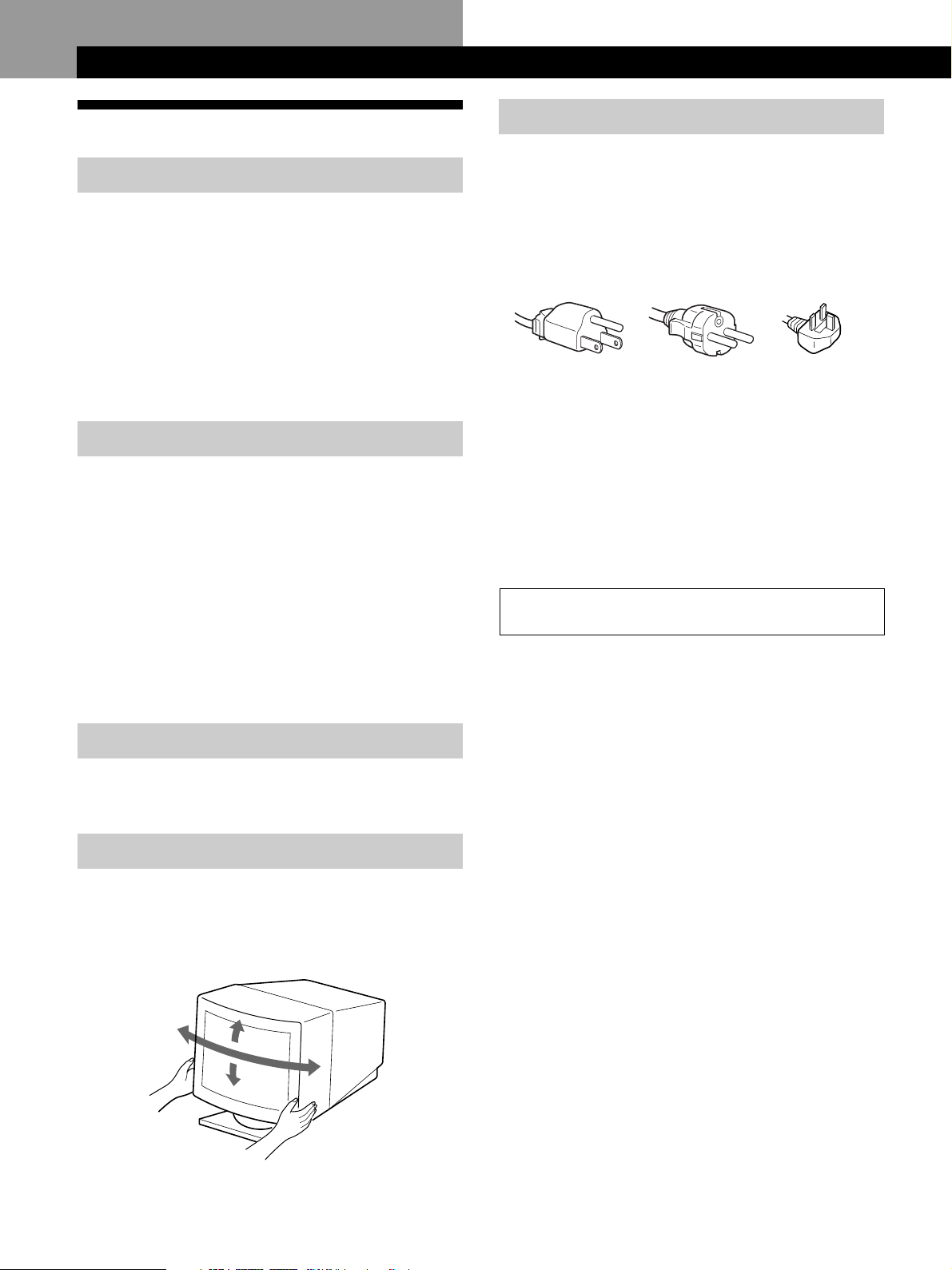
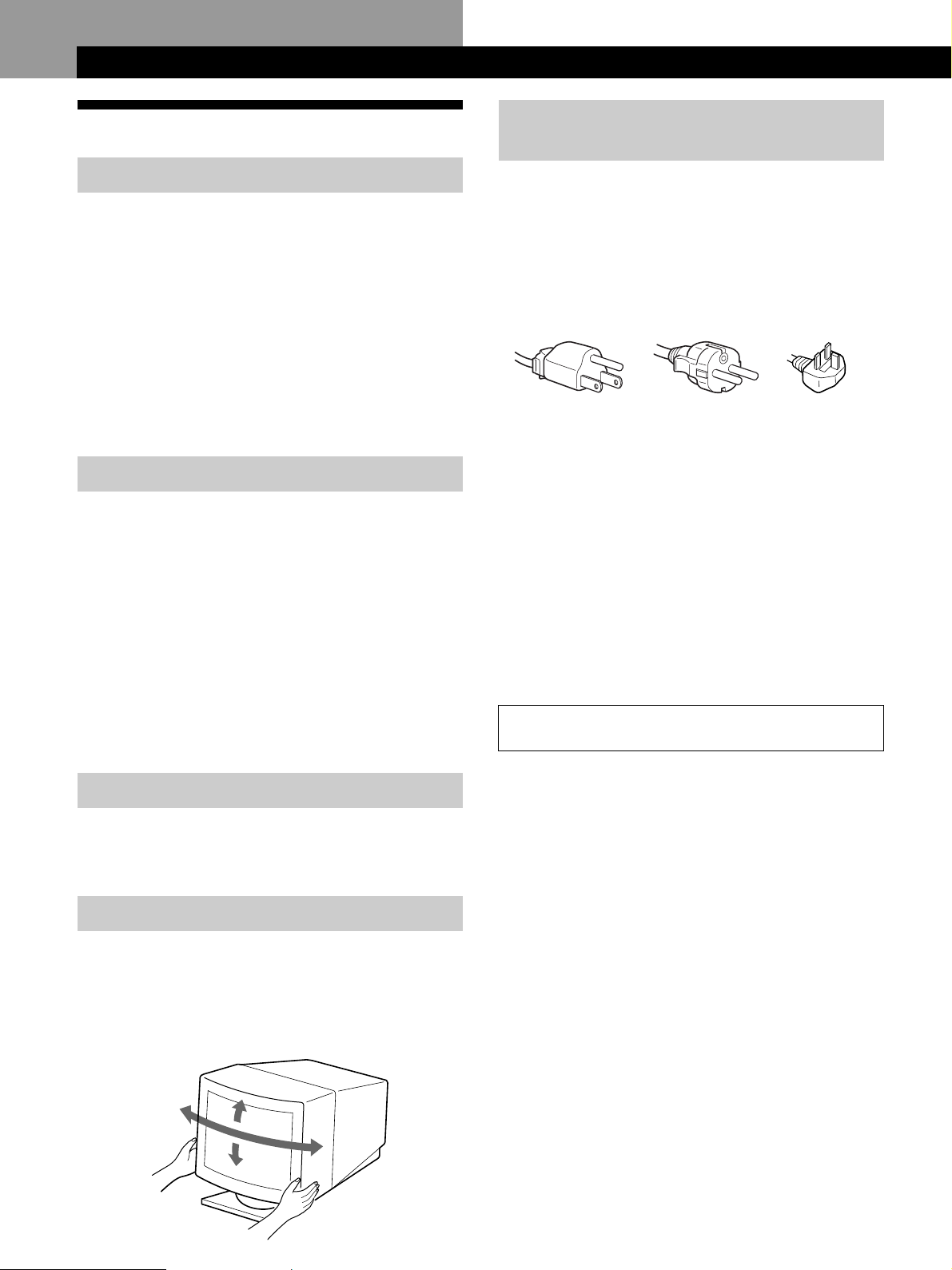
Use of the Tilt-Swivel
With the tilt-swivel, this monitor can be adjusted to the
desired angle within 180° horizontally and 20° vertically.
To turn the monitor vertically and horizontally, hold it at
the bottom with both hands as illustrated below.
15°
90°
90°
5°
4
Page 5
Identifying Parts and Controls
See the pages in parentheses for further details.
Getting Started
Getting Started
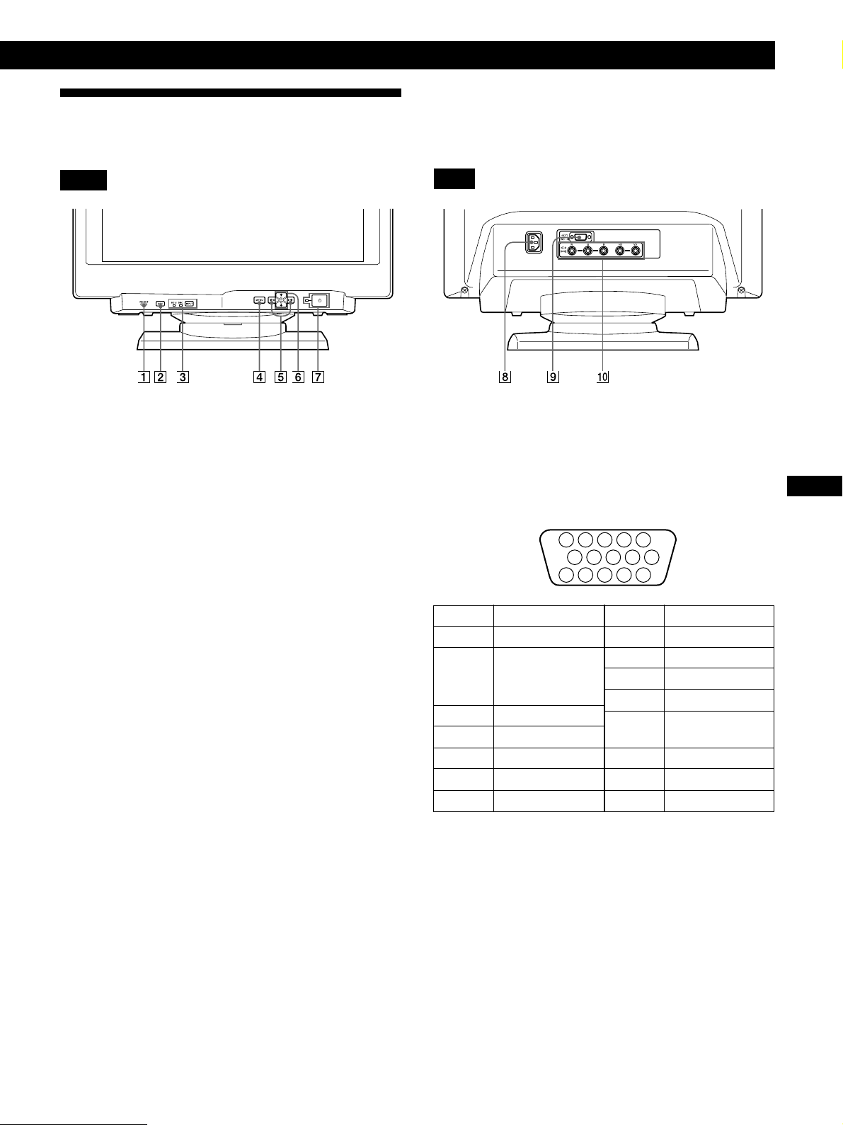
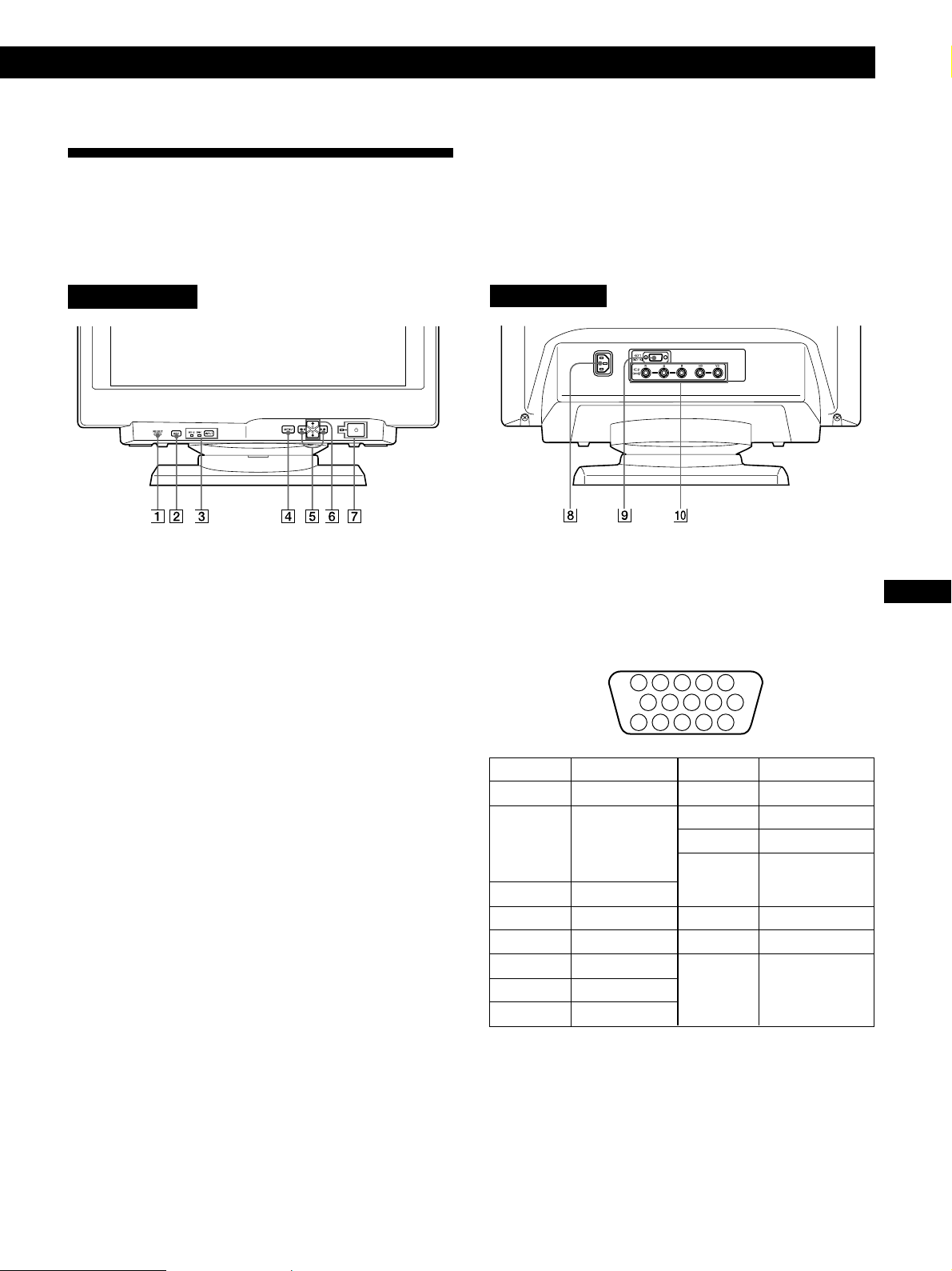
Front
1 RESET (reset) button (page 17)
Resets the adjustments to the factory settings.
2 ASC (auto sizing and centering) button
(page 7)
Automatically adjusts the size and centering of the
images.
3 INPUT (input) button and HD15/BNC
indicators (page 8)
Selects the HD15 or 5BNC video input signal. Each time
you press this button, the input signal and
corresponding indicator alternate.
4 MENU (menu) button (pages 8 -17, 19)
Displays the MENU OSD.
5 > (contrast) (?//) buttons (pages 8 – 17,
22)
Adjust the contrast.
Function as the (?//) buttons when adjusting other
items.
6 ¨ (brightness) (./>) buttons (pages 8 –
17)
Adjust the picture brightness.
Rear
8 AC IN connector
Provides AC power to the monitor.
9 Video input 1 connector (HD15)
Inputs RGB video signals (0.700 Vp-p, positive) and
SYNC signals.
5 4 3 2
Pin No.
1
2
3
4
5
6
7
* Display Data Channel (DDC) Standard of VESA
Signal
Red
Green
(Composite
Sync on Green)
Blue
ID (Ground)
DDC Ground*
Red Ground
Green Ground
1
1112131415
Pin No.
8
9
10
11
12
13
14
15
678910
Signal
Blue Ground
DDC + 5V*
Ground
ID (Ground)
Bi-Directional
Data (SDA)*
H. Sync
V. Sync
Data Clock(SCL)*
GB
FR
DE
ES
Function as the (./>) buttons when adjusting other
items.
7 u (power) switch and indicator (pages 19,
22)
Turns the monitor on or off.
The indicator lights up in green when the monitor is
turned on, and either flashes in green and orange or
lights up in orange when the monitor is in power
saving mode.
!º Video input 2 connector (5 BNC)
Inputs RGB video signals (0.700 Vp-p, positive) and
SYNC signals.
5
Page 6
Getting Started
Setup
Before using this monitor, check that the following items are
included in your carton:
• Monitor (1)
• Power cord (1)
• HD15 video signal cable (1)
• Macintosh adapter (1)
• Windows Monitor Information Disk (1)
• Warranty card (1)
• Notes on cleaning the screen’s surface (1)
• These operating instructions (1)
This monitor works with any IBM or compatible system
equipped with VGA or greater graphics capability.
Although this monitor works with other platforms running
at horizontal frequencies between 30 and 96 kHz, including
Macintosh and Power Macintosh systems, a cable adapter is
required. Please consult your dealer for advice on which
adapter is suitable for your needs.
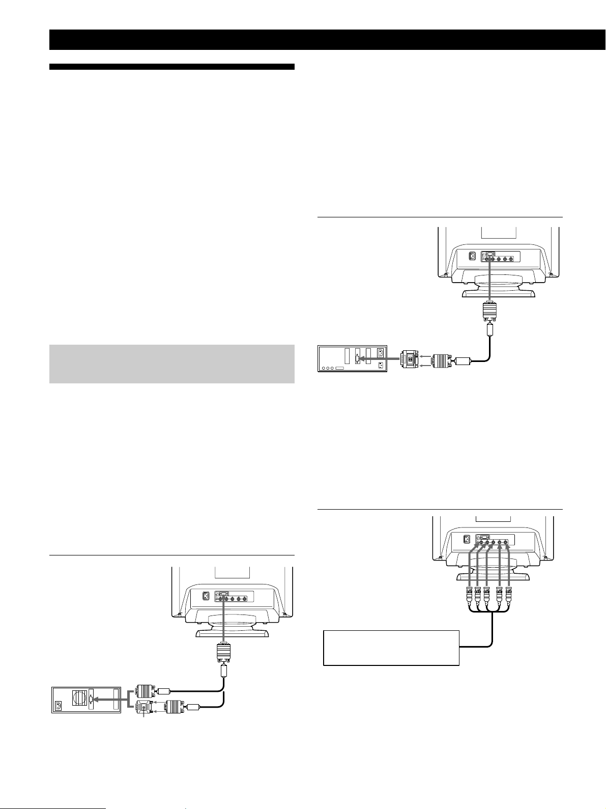
Step 1: Connect the monitor to the
computer
With the computer switched off, connect the video signal
cable to the monitor using the supplied HD15 video signal
cable.
• If you are using an IBM PC/AT or compatible computer,
refer to the section below.
• If you are using a Macintosh or compatible computer,
refer to the following section, “Connecting to a Macintosh
or compatible computer.”
• If you want to use the 5 BNC connectors, refer to the
section, “Connecting to the 5 BNC connectors.”
If your PC system is not compatible with DDC2AB
and DDC2B+
This monitor uses the No. 9 pin in the video signal connector for
DDC2AB and DDC2B+ compatibility.
Some PC systems which are not compatible with either DDC2AB or
DDC2B+ may not accept the No. 9 pin. If you are not sure whether
your PC system accepts the No. 9 pin or not, use the HD15 (Female)
- HD15 (Male without the No. 9 pin) adapter (not supplied). Make
sure the male side (without the No. 9 pin) is connected to the
computer.
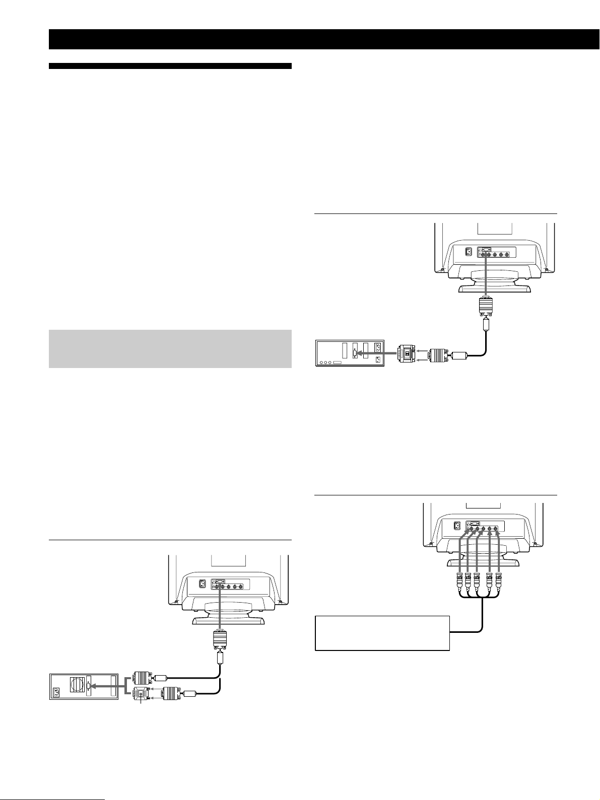
Connecting to a Macintosh or compatible
computer
to HD15
Macintosh or
compatible
computer
to video output
Macintosh adapter
(supplied)
HD15 video
signal cable
(supplied)
About the supplied Macintosh adapter
The supplied Macintosh adapter is compatible with Macintosh LC,
Performa, Quadra, Power Macintosh and Power Macintosh G3
series computers.
Macintosh II series and some older versions of Power Book models
may need an adapter with micro switches (not supplied).
Connecting to the 5 BNC connectors
Connecting to an IBM PC/AT or compatible
computer
to HD15
IBM PC/AT or
compatible
computer
* The HD15 - HD15 adapter may be needed for some models.
to video output
HD15 - HD15 adapter
(not supplied)∗
HD15 video
signal cable
(supplied)
6
to VIDEO IN R/G/B
Connect to the computer in
the same way as for the HD15
connector.
to SYNC IN HD/VD
To connect the 5 BNC connectors, use the SMF-400 video
signal cable (sold separately). Connect the cables from left to
right in the following order: Red–Green–Blue–HD–VD.
Notes
• Do not short the pins of the video signal cable.
• The DDC standard does not apply to the 5 BNC connectors. If
you use the DDC standard, connect the HD15 connector to the
computer with the supplied video signal cable.
Page 7
Getting Started
Getting Started
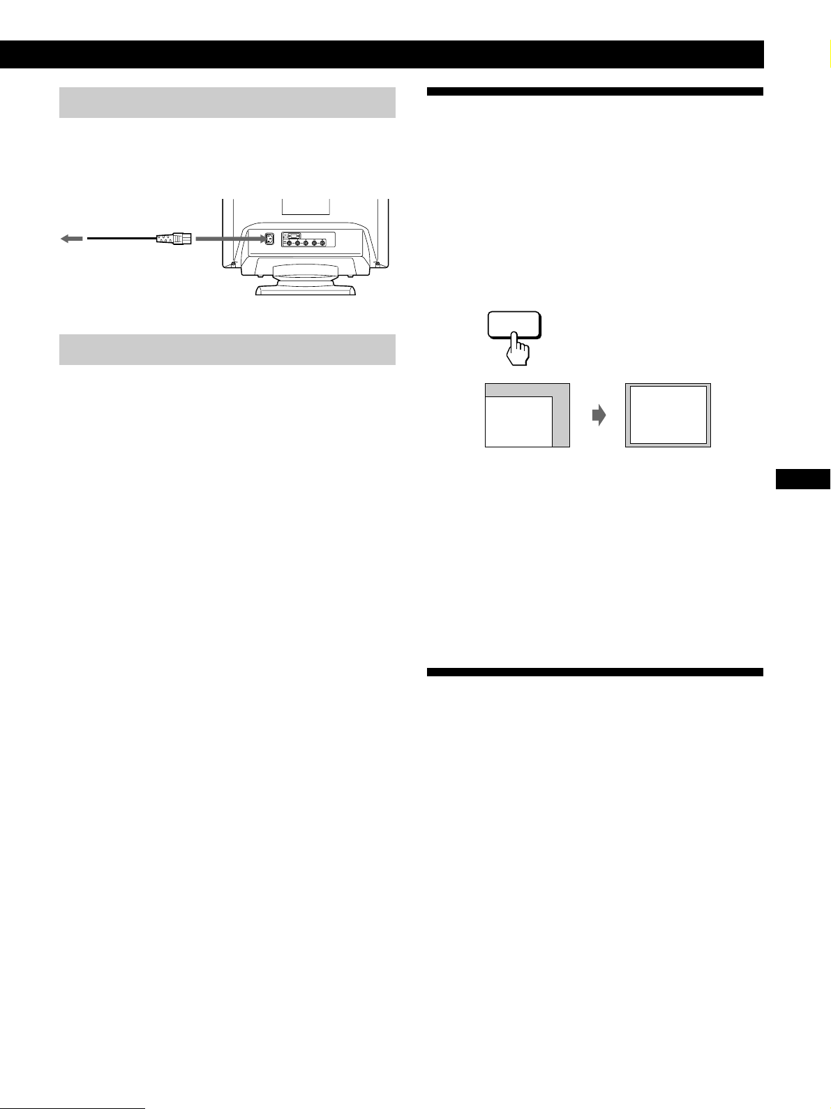
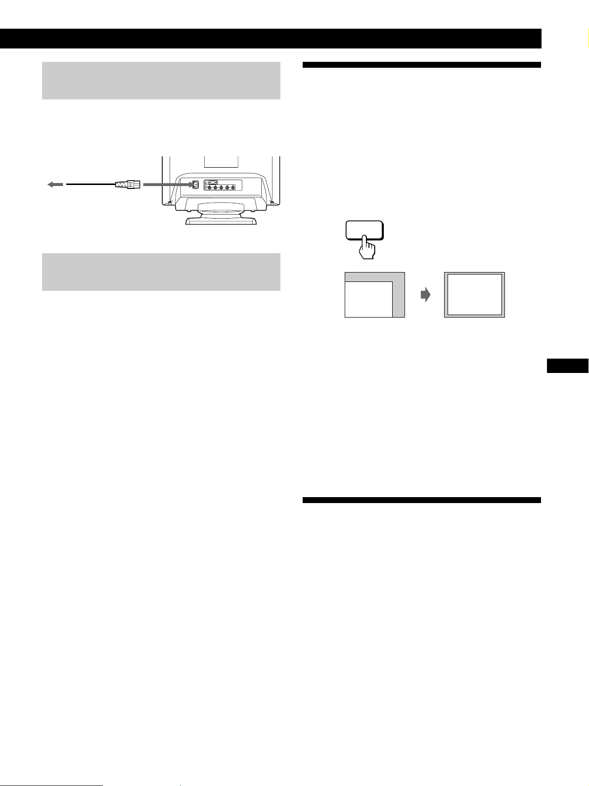
Step 2: Connect the power cord
With the monitor switched off, connect one end of the
power cord to the monitor and the other end to a power
outlet.
to a power outlet
Power cord (supplied)
to AC IN
Step 3: Turn on the monitor and computer
The installation of your monitor is complete.
Note
If “OUT OF SCAN RANGE” or “NO INPUT SIGNAL” appears on
the screen, see “Warning Messages” on page 20.
For customers using Windows 95/98
To maximize the potential of your monitor, install the new model
information file from the supplied Windows Monitor Information
Disk onto your PC.
This monitor complies with the “VESA DDC” Plug & Play
standard. If your PC/graphics board complies with DDC, select
“Plug & Play Monitor (VESA DDC)” or this monitor’s model name
as the monitor type in the “Control Panel” of Windows 95/98.
If your PC/graphics board has difficulty communicating with this
monitor, load the Windows Monitor Information Disk and select
this monitor’s model name as the monitor type.
Automatically Adjusting the Size
and Centering of the Picture
By pressing the auto sizing and centering (ASC) button, the
size and centering of the picture are automatically adjusted
to fit the screen.
1 Turn on the monitor and computer.
2 Press the ASC button.
The picture is adjusted to fit the center of the screen.
ASC
Notes
• This function is intended for use with a computer running
Windows or similar graphic user interface software that
provides a full-screen picture. It may not work properly if the
background color is dark or if the input picture does not fill the
screen to the edges (such as an MS-DOS prompt).
• The screen may go blank for a few seconds while performing the
auto-sizing function. This is not a malfunction.
• Although the signals for picture aspect ratio 5:4 (resolution: 1280
× 1024) do not fill the screen to the edges, the picture is
accurately displayed.
GB
FR
DE
ES
For customers using Windows NT4.0
Monitor setup in Windows NT4.0 is different from Windows 95/98
and does not involve the selection of monitor type. Refer to the
Windows NT4.0 instruction manual for further details on adjusting
the resolution, refresh rate, and number of colors.
Selecting the On-screen Display
Language
If you need to change the OSD language, see “Using the
LANG (Language) On-screen Display” on page 17.
The default setting is English.
7
Page 8
Getting Started
AUTO
ZZ...
INPUT
1 MIN
OPTION
UNLOCK
MANUAL
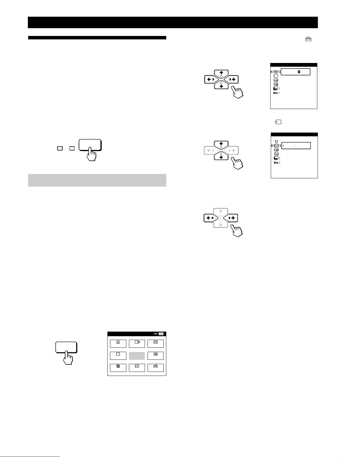
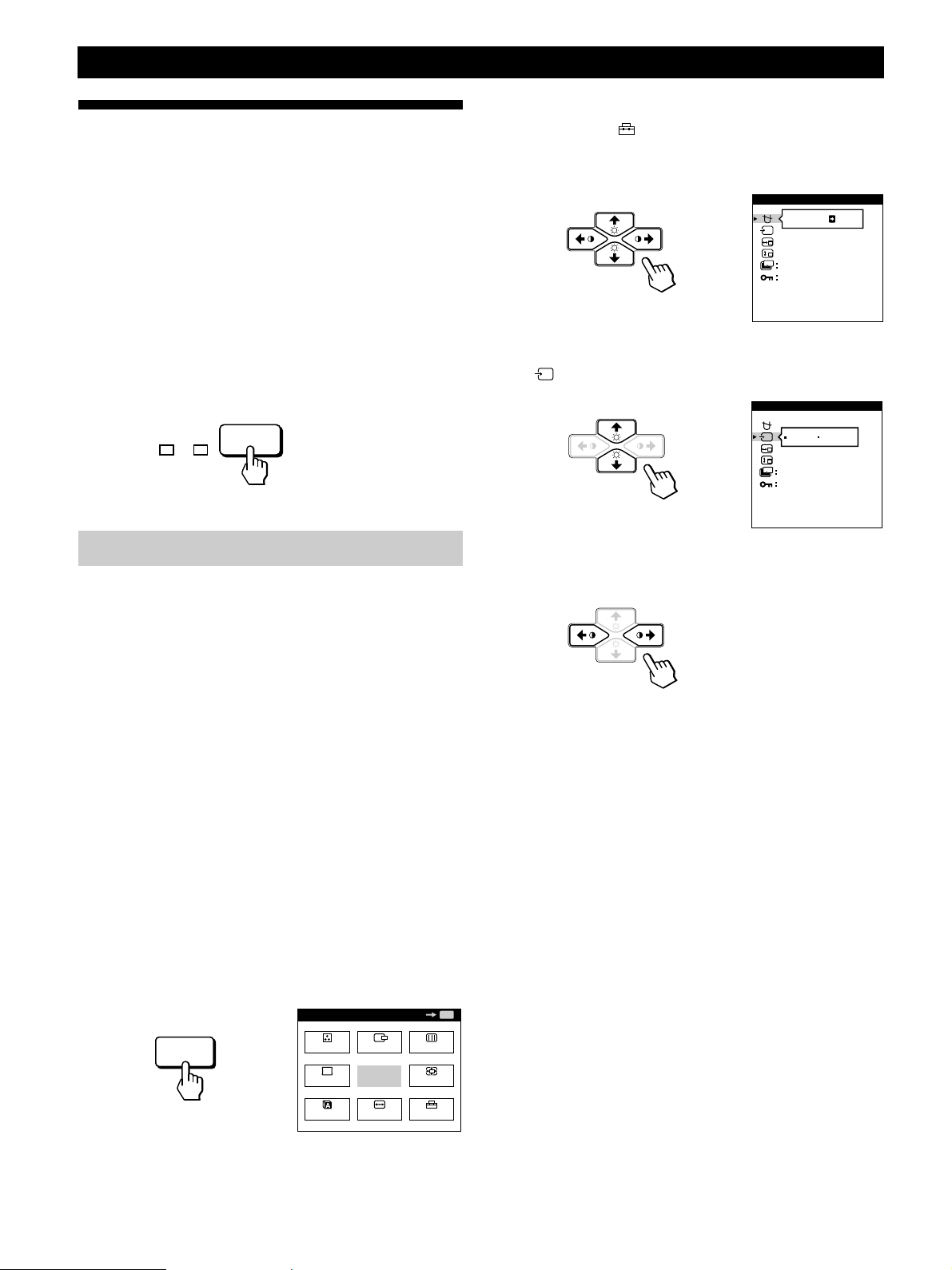
Selecting the Input Signal
This monitor has two signal input connectors (HD15 and
5BNC) and can be connected to two computers. When the
power of both computers is on, select the input signal you
want to view as follows.
1 Turn on the monitor and both computers.
2 Press the INPUT button to select the HD15 or 5BNC
input signal.
Each time you press the INPUT button, the input signal
and corresponding indicator alternate.
2 Press the ¨./> and >?// buttons to select “
OPTION,” and press the MENU button again.
The OPTION OSD appears.
OPTION
ON
ZZ...
1 MIN
UNLOCK
MANUAL DEGAUSS
3 Press the ¨./> buttons to select “ (INPUT).”
HD15 BNC
INPUT
Selecting the INPUT signal mode
This monitor has two modes of input signal selection,
“AUTO” and “MANUAL.”
When “AUTO” is selected
If no signal is input from the selected connector, the monitor
automatically selects the other connector’s signal. When you
restart the computer you want to view, or that computer is
in power saving mode, the monitor may automatically
select the other connector’s signal. This is because the
monitor switches from the interrupted signal to the constant
signal. If this happens, manually select the desired signal
using the INPUT button.
When “MANUAL” is selected
Even if no signal is input from the selected connector, the
monitor does not select the other connector’s signal.
4 Press the >?// buttons to select “AUTO” or
“MANUAL.”
The OPTION OSD automatically disappears after about 30
seconds.
To close the OSD, press the MENU button again.
For more information on using the OSD, see “Introducing
the On-screen Display System” on page 9.
1 Press the MENU button.
The MENU OSD appears.
MENU
8
MENU
COLOR
GEOM
LANG
CENTER
EXIT
SIZE
OK
SCREEN
ZOOM
OPTION
MENU
Page 9
Customizing Your Monitor
MENU
Before adjusting
• Connect the monitor and the computer, and turn them on.
• Select “
“ENGLISH” (see page 17).
LANG” in the MENU OSD, then select
Getting Started
Customizing Your Monitor
Introducing the On-screen
Display System
Most adjustments are made using the MENU OSD.
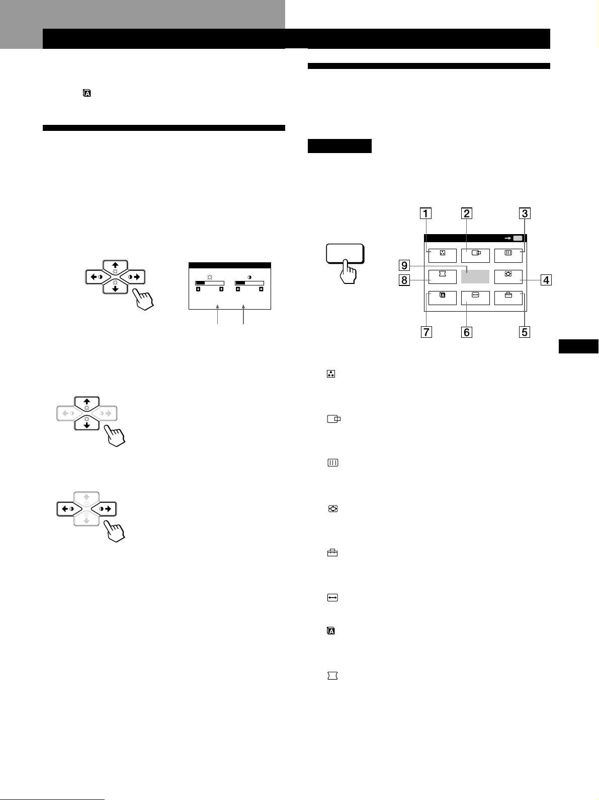
Adjusting the Picture Brightness
and Contrast
Once the setting is adjusted, it will be stored in memory for
all input signals received.
1 Press the ¨ (brightness) ./> or > (contrast) ?//
buttons.
The BRIGHTNESS/CONTRAST OSD appears.
BRIGHTNESS/CONTRAST
26 26
80.0kHz/ 75Hz
Horizontal
Frequency*
2 For brightness adjustment
Press the ¨./> buttons.
> . . . for more brightness
. . . . for less brightness
Vertical
Frequency*
MENU OSD
Press the MENU button to display the MENU OSD.
This MENU OSD contains links to the other OSDs described
below.
MENU
GEOM
LANG
CENTER
EXIT
SIZE
COLOR
1 COLOR
Displays the COLOR OSD for adjusting the color
temperature.
2 CENTER
Displays the CENTER OSD for adjusting the centering
of the picture.
OK
SCREEN
ZOOM
OPTION
MENU
GB
FR
DE
ES
For contrast adjustment
Press the >?// buttons.
/ . . . for more contrast
? . . . for less contrast
The OSD automatically disappears after about 3 seconds.
To reset, press the RESET button while the OSD is on. The
brightness and contrast are both reset to the factory settings.
* The horizontal and vertical frequencies for the received input
signal appear in the BRIGHTNESS/CONTRAST OSD.
3 SCREEN
Displays the SCREEN OSD for adjusting the vertical
and horizontal convergence, etc.
4 ZOOM
Displays the ZOOM OSD for enlarging and reducing
the picture.
5 OPTION
Displays the OPTION OSD for adjusting the OSD
position and degaussing the screen, etc.
6 SIZE
Displays the SIZE OSD for adjusting the picture size.
7 LANG
Displays the LANGUAGE OSD for selecting the
language.
8 GEOM
Displays the GEOMETRY OSD for adjusting the picture
rotation and pincushion, etc.
9 EXIT
Closes the MENU OSD.
9
Page 10
Customizing Your Monitor
Using the CENTER On-screen
Display
The CENTER settings allow you to adjust the centering of
the picture.
Once the setting is adjusted, it will be stored in memory for
the current input signal.
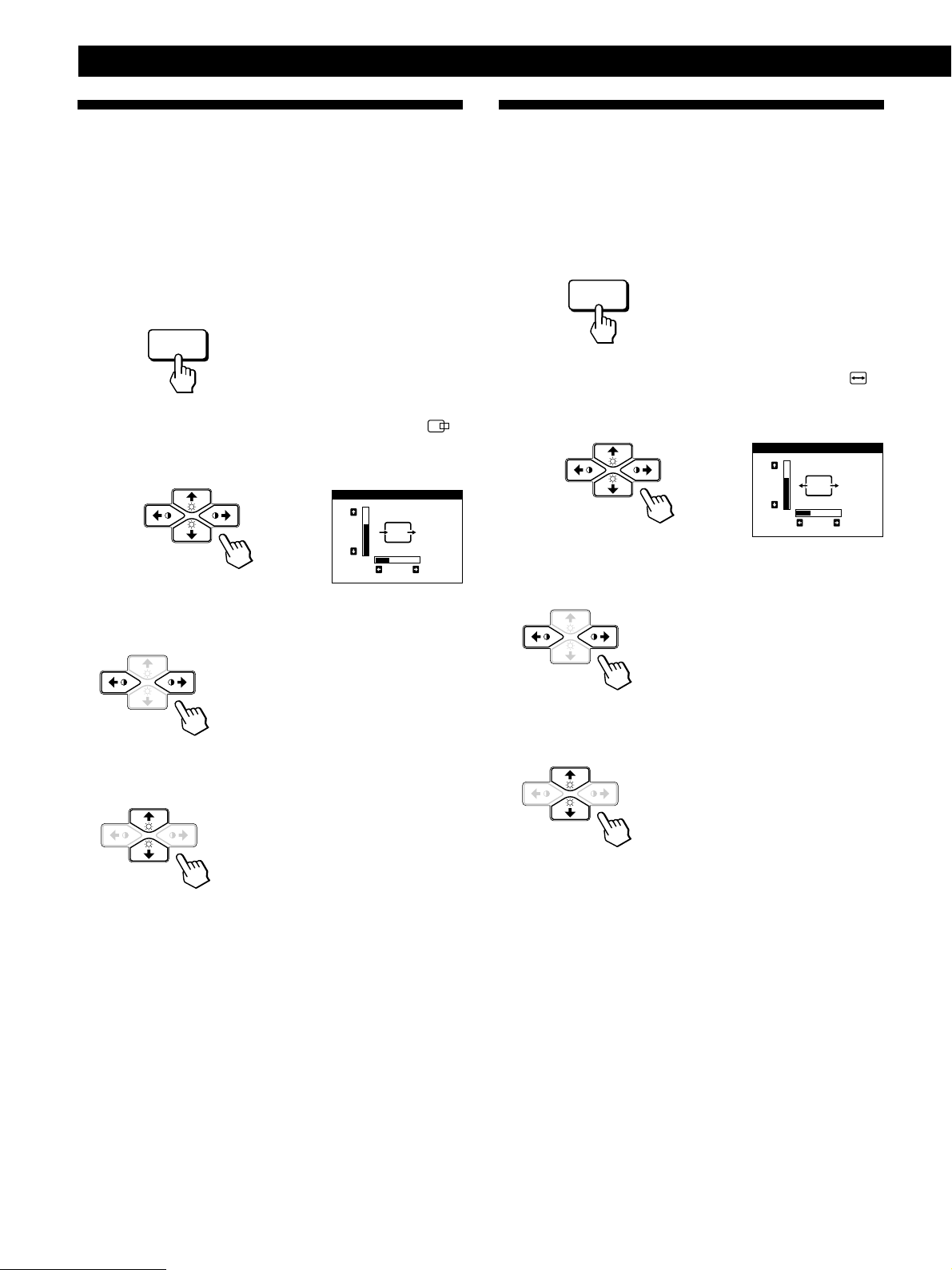
1 Press the MENU button.
The MENU OSD appears.
MENU
2 Press the ¨./> and >?// buttons to select “
CENTER,” and press the MENU button again.
The CENTER OSD appears.
CENTER
73
26
Using the SIZE On-screen Display
The SIZE settings allow you to adjust the size of the picture.
Once the setting is adjusted, it will be stored in memory for
the current input signal.
1 Press the MENU button.
The MENU OSD appears.
MENU
2 Press the ¨./> and >?// buttons to select “
SIZE,” and press the MENU button again.
The SIZE OSD appears.
SIZE
73
26
3 For horizontal adjustment
Press the >?// buttons.
3 For horizontal adjustment
Press the >?// buttons.
/ . . . to move the picture right
? . . . to move the picture left
For vertical adjustment
Press the ¨./> buttons.
> . . . to move the picture up
. . . . to move the picture down
The OSD automatically disappears after about 30 seconds.
To close the OSD, press the MENU button again.
To reset, press the RESET button while the OSD is on.
The horizontal and vertical centerings are both reset to the
factory settings.
/ . . . to increase picture size
? . . . to decrease picture size
For vertical adjustment
Press the ¨./> buttons.
> . . . to increase picture size
. . . . to decrease picture size
The OSD automatically disappears after about 30 seconds.
To close the OSD, press the MENU button again.
To reset, press the RESET button while the OSD is on.
The horizontal and vertical sizes are both reset to the factory
settings.
10
Page 11
Using the GEOM (Geometry) Onscreen Display
The GEOM (geometry) settings allow you to adjust the
shape and orientation of the picture.
Once the rotation is adjusted, it will be stored in memory for
all input signals received. All other adjustments will be
stored in memory for the current input signal.
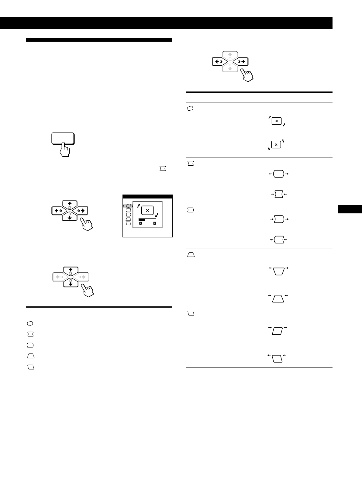
1 Press the MENU button.
The MENU OSD appears.
MENU
Getting Started
Customizing Your Monitor
4 Press the >?// buttons to adjust the settings.
For
ROTATION
Press
/ . . . to rotate the picture clockwise
? . . . to rotate the picture counterclockwise
2 Press the ¨./> and >?// buttons to select “
GEOM,” and press the MENU button again.
The GEOMETRY OSD appears.
GEOMETRY
26
ROTATION
3 Press the ¨./> buttons to select the item you want
to adjust.
Select
ROTATION
PINCUSHION
PIN BALANCE
KEYSTONE
To
adjust the picture rotation
adjust the picture sides
adjust the picture side balance
adjust the picture width
PINCUSHION
PIN BALANCE
KEYSTONE
KEY BALANCE
/ . . . to expand the picture sides
? . . . to contract the picture sides
/ . . . to move the picture sides to the right
? . . . to move the picture sides to the left
/ . . . to increase the picture width at the
top
? . . . to decrease the picture width at the
top
/ . . . to move the top of the picture to
the right
? . . . to move the top of the picture to
the left
GB
FR
DE
ES
KEY BALANCE
adjust the picture shape balance
The OSD automatically disappears after about 30 seconds.
To close the OSD, press the MENU button again.
To reset, press the RESET button while the OSD is on.
The selected item is reset to the factory setting.
11
Page 12
Customizing Your Monitor
MENU
Using the ZOOM On-screen
Display
The ZOOM settings allow you to enlarge or reduce the
picture.
Once the setting is adjusted, it will be stored in memory for
the current input signal.
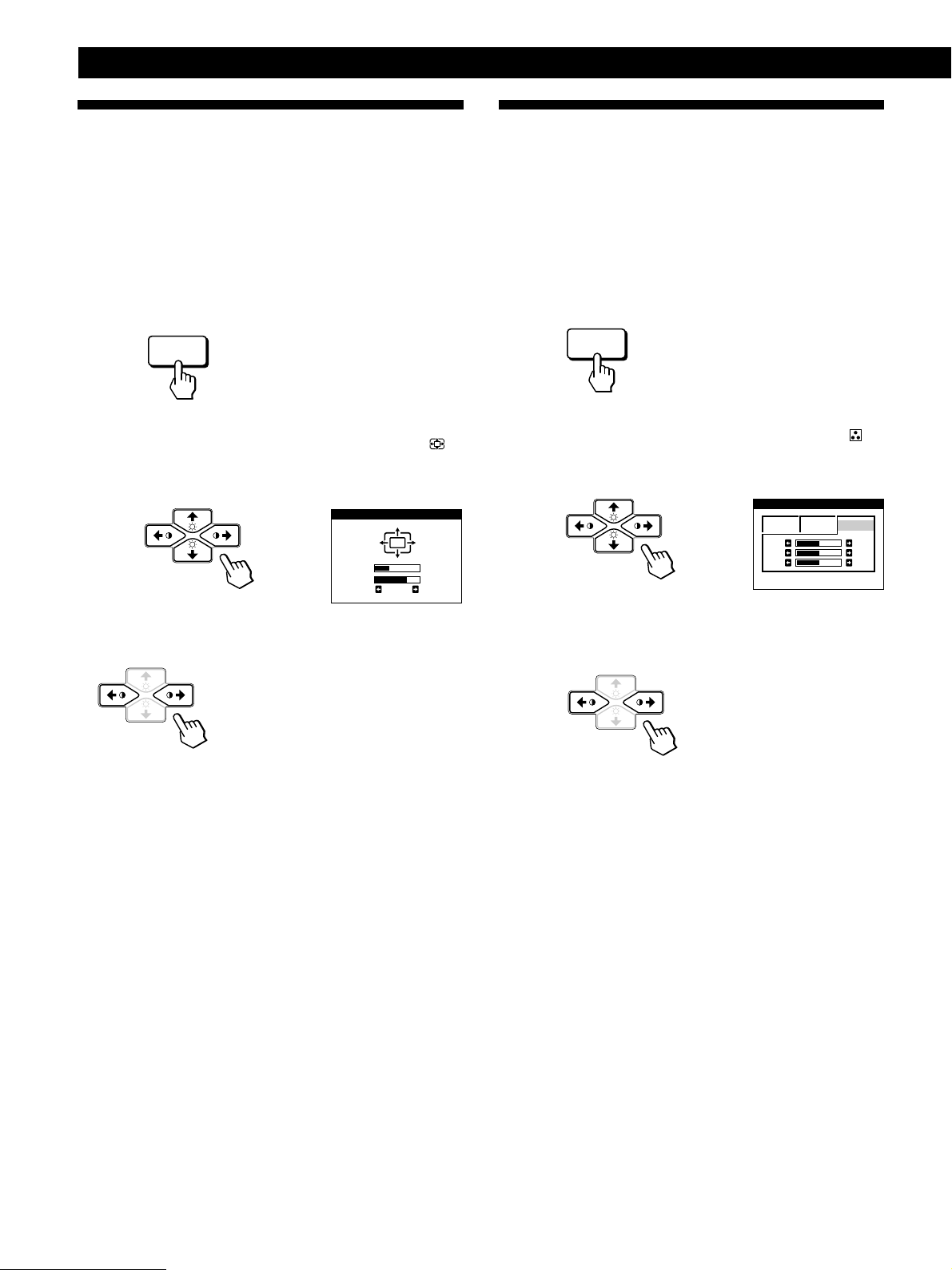
1 Press the MENU button.
The MENU OSD appears.
MENU
2 Press the ¨./> and >?// buttons to select “
ZOOM,” and press the MENU button again.
The ZOOM OSD appears.
ZOOM
26H
73V
Using the COLOR On-screen Display
You can change the monitor’s color temperature. For
example, you can adjust or change the colors of a picture on
the screen to match the actual colors of the printed picture.
Once the setting is adjusted, it will be stored in memory for
all input signals received.
1 Press the MENU button.
The MENU OSD appears.
2 Press the ¨./> and >?// buttons to select “
COLOR,” and press the MENU button again.
The COLOR OSD appears.
COLOR
5000K 6500K 9300K
R
G
B
50
50
50
3 Press the >?//buttons to adjust the picture zoom.
/ . . . to enlarge the picture
? . . . to reduce the picture
The OSD automatically disappears after about 30 seconds.
To close the OSD, press the MENU button again.
To reset, press the RESET button while the OSD is on.
Note
The picture zoom adjustment will stop as soon as either the
horizontal or vertical size reaches its maximum or minimum value.
3 Press the >?// buttons to select the color
temperature.
There are three color temperature modes in the OSD.
The preset adjustments are:
5000K, 6500K, 9300K
12
Page 13
MENU
4 Fine tuning the color temperature
Press the ¨./> buttons to select R (red), G (green), or B
(blue) and adjust by pressing the >?// buttons.
COLOR
1 6500K 9300K
R
G
B
The “5000K,” “6500K” or “9300K” disappears and the
new color settings are memorized for each of the three
color modes.
The color temperature modes change as follows:
5000Kn 1, 6500Kn 2, 9300Kn 3
Getting Started
Customizing Your Monitor
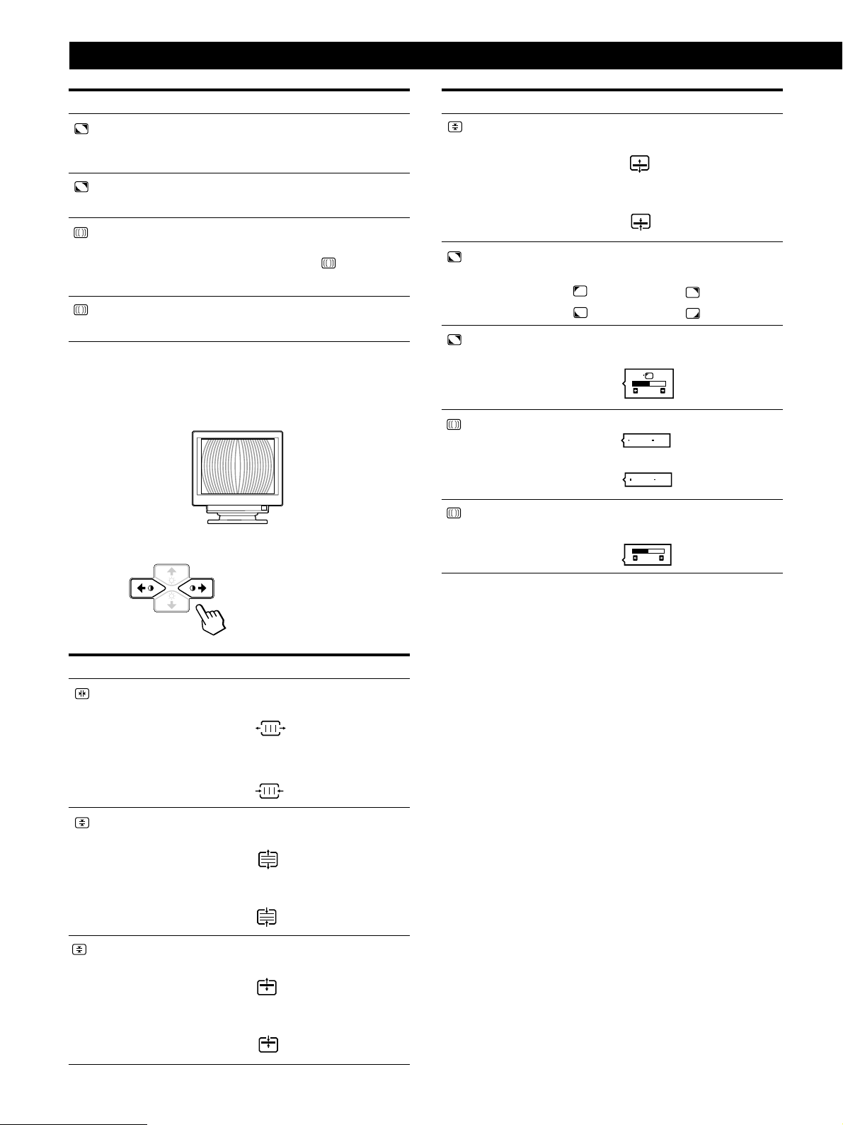
Using the SCREEN On-screen
Display
You can adjust convergence settings to eliminate red or blue
76
50
50
shadows that may appear around objects on the screen.
Adjust the CANCEL MOIRE function to eliminate wavy or
elliptical patterns that may appear on the screen.
Adjust the LANDING function to correct color imbalances
at the four corners of the screen due to influence from the
earth’s magnetism.
Once CANCEL MOIRE is adjusted, it will be stored in
memory for the current input signal. All other adjustments
will be stored in memory for all input signals received.
The OSD automatically disappears after about 30 seconds.
To close the OSD, press the MENU button again.
To reset, press the RESET button while the OSD is on. The
selected item is reset to the factory settings.
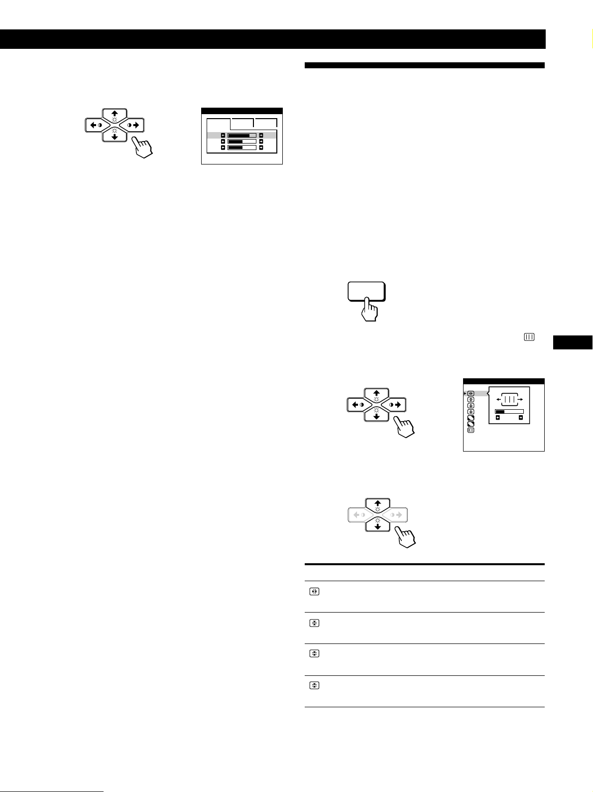
1 Press the MENU button.
The MENU OSD appears.
2 Press the ¨./> and >?// buttons to select “
SCREEN,” and press the MENU button again.
The SCREEN OSD appears.
SCREEN
TOP
BOT
ADJ
H CONVERGENCE
26
3 Press the ¨./> buttons to select the item you want
to adjust.
GB
FR
DE
ES
Select
H CONVERGENCE
V CONVERGENCE
TOP
V CONVER TOP
BOT
V CONVER BOTTOM
To
adjust the horizontal convergence
adjust the vertical convergence
adjust the screen’s upper vertical
convergence
adjust the screen’s lower vertical
convergence
(continued)
13
Page 14
Customizing Your Monitor
ON
OFF
Select
LANDING
ADJ
LANDING ADJUST
CANCEL MOIRE *
ADJ
MOIRE ADJUST
* Moire is a type of natural interference which produces soft or
wavy lines on your screen. It may appear due to interference
between the regulated pattern of the picture from the input
signal and the phosphor pitch pattern of the CRT.
Example of moire:
To
select one of the four corners that
needs color correction due to
influence from the earth’s magnetism
correct the color at one of the four
corners of the screen
turn the moire cancellation function
“ON” or “OFF.” CANCEL MOIRE
must be “ON” for “ ADJ (MOIRE
ADJUST)” to appear on the screen.
adjust the degree of moire
cancellation
For
BOT
V CONVER BOTTOM
LANDING
ADJ
LANDING ADJUST
CANCEL MOIRE
Press
/ . . . to shift red shadows up and blue
shadows down
? . . . to shift red shadows down and
blue shadows up
/ or ? . . . to select the corner of the
screen you want to adjust
: top left : top right
: bottom left : bottom right
/ or ? . . . to reduce any irregularities in
the color to a minimum
50
/ . . . to turn CANCEL MOIRE “ON”
ON
OFF
? . . . to turn CANCEL MOIRE “OFF”
4 Press the >?// buttons to adjust the settings.
For
H CONVERGENCE
V CONVERGENCE
Press
/ . . . to shift red shadows to the right
and blue shadows to the left
? . . . to shift red shadows to the left
and blue shadows to the right
/ . . . to shift red shadows up and blue
shadows down
? . . . to shift red shadows down and
blue shadows up
ADJ
MOIRE ADJUST
/ or ? . . . to adjust the screen until the
moire is at a minimum
50
Note
The picture may become fuzzy when CANCEL MOIRE is set to
“ON.”
The OSD automatically disappears after about 30 seconds.
To close the OSD, press the MENU button again.
To reset, press the RESET button while the OSD is on.
The selected item is reset to the factory setting.
14
TOP
V CONVER TOP
/ . . . to shift red shadows up and blue
shadows down
? . . . to shift red shadows down and
blue shadows up
Page 15
Getting Started
MENU
Customizing Your Monitor
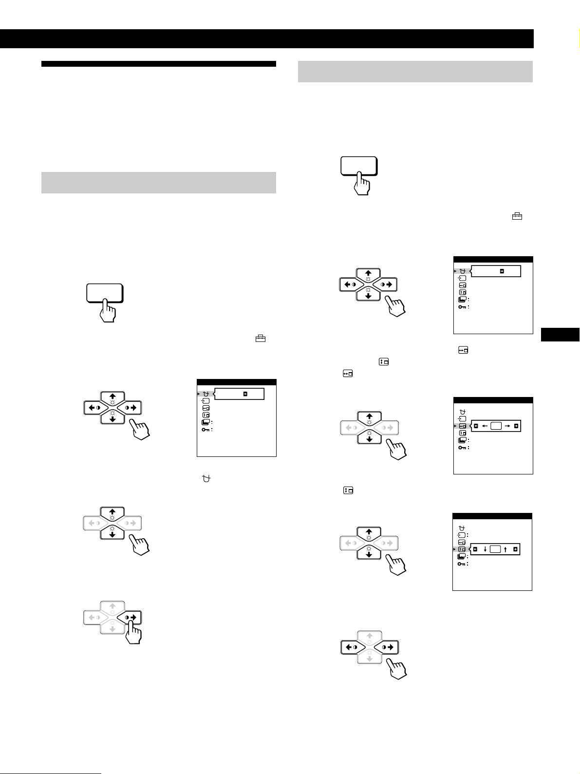
Using the OPTION On-screen
Display
The OPTION OSD allows you to manually degauss the
screen and adjust settings such as the OSD position and
power saving delay time. It also allows you to lock the
controls.
Degaussing the screen
The monitor screen is automatically degaussed
(demagnetized) when the power is turned on.
You can also manually degauss the monitor.
1 Press the MENU button.
The MENU OSD appears.
MENU
2 Press the ¨./> and >?// buttons to select “
OPTION,” and press the MENU button again.
The OPTION OSD appears.
OPTION
ON
ZZ...
1 MIN
UNLOCK
MANUAL DEGAUSS
Changing the on-screen display position
You can change the OSD position (for example, when you
want to adjust the picture behind the OSD).
1 Press the MENU button.
The MENU OSD appears.
2 Press the ¨./> and >?// buttons to select “
OPTION,” and press the MENU button again.
The OPTION OSD appears.
OPTION
ON
ZZ...
1 MIN
UNLOCK
MANUAL DEGAUSS
3 Press the ¨./> buttons to select “ (OSD H
POSITION)” or “
Select “
(OSD H POSITION)” to adjust the horizontal
position.
(OSD V POSITION).”
OPTION
ZZ...
1 MIN
UNLOCK
GB
FR
DE
ES
3 Press the ¨./> buttons to select “ (MANUAL
DEGAUSS).”
4 Press the > / button.
The screen is degaussed for about 3 seconds.
If you need to degauss the screen a second time, wait for at
least 20 minutes before repeating the steps above.
The OPTION OSD automatically disappears after about 30
seconds.
To close the OSD, press the MENU button again.
OSD H POSITION
Select “
(OSD V POSITION)” to adjust the vertical
position.
OPTION
AUTO
ZZ...
UNLOCK
OSD V POSITION
4 Press the >?// buttons to move the OSD to the
desired position.
The OPTION OSD automatically disappears after about 30
seconds.
To close the OSD, press the MENU button again.
To reset, press the RESET button while the OSD is on.
15
Page 16
Customizing Your Monitor
MENU
ZZ...
CONTROL LOCK
OPTION
UNLOCK LOCK
AUTO
Setting the power saving delay time
You can set the delay time before the monitor enters the
power saving mode. See page 19 for more information on
this monitor’s power saving capabilities.
1 Press the MENU button.
The MENU OSD appears.
MENU
2 Press the ¨./> and >?// buttons to select “
OPTION,” and press the MENU button again.
The OPTION OSD appears.
OPTION
ON
ZZ...
1 MIN
UNLOCK
MANUAL DEGAUSS
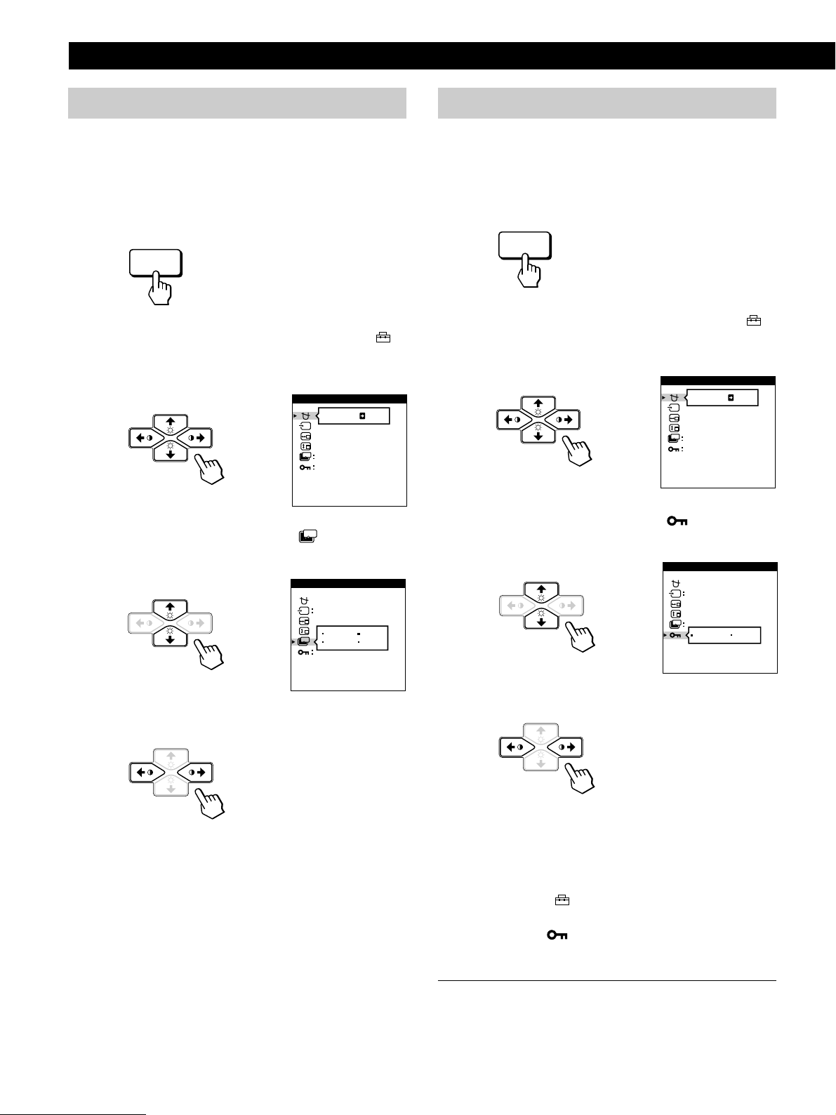
Locking the controls
The control lock function disables all of the buttons on the
front panel except the u (power) switch and MENU button.
1 Press the MENU button.
The MENU OSD appears.
2 Press the ¨./> and >?// buttons to select “
OPTION,” and press the MENU button again.
The OPTION OSD appears.
OPTION
ON
ZZ...
1 MIN
UNLOCK
MANUAL DEGAUSS
3 Press the ¨./> buttons to select “
ZZ...
(PWR SAVE
DELAY).”
OPTION
AUTO
5 SEC
60 MIN
1 MIN
OFF
ZZ...
PWR SAVE DELAY
4 Press the >?// buttons to select the desired time.
When PWR SAVE DELAY is set to “OFF,” the monitor
does not go into power saving mode.
The OPTION OSD automatically disappears after about 30
seconds.
To close the OSD, press the MENU button again.
3 Press the ¨./> buttons to select “ (CONTROL
LOCK).”
4 Press the >?// buttons to select “LOCK.”
The OPTION OSD automatically disappears after about 30
seconds.
To close the OSD, press the MENU button again.
Once you select “LOCK,” you cannot select any items
except “EXIT” and “
If you press any button other than the u (power) switch and
MENU button, the
OPTION” in the MENU OSD.
mark appears on the screen.
To reset, press the RESET button while the OSD is on.
16
To cancel the control lock
Repeat steps 1 through 3 above and press the >?//
buttons to select “UNLOCK.”
Page 17
Getting Started
MENU
RESET
RESET
RESET
Customizing Your Monitor
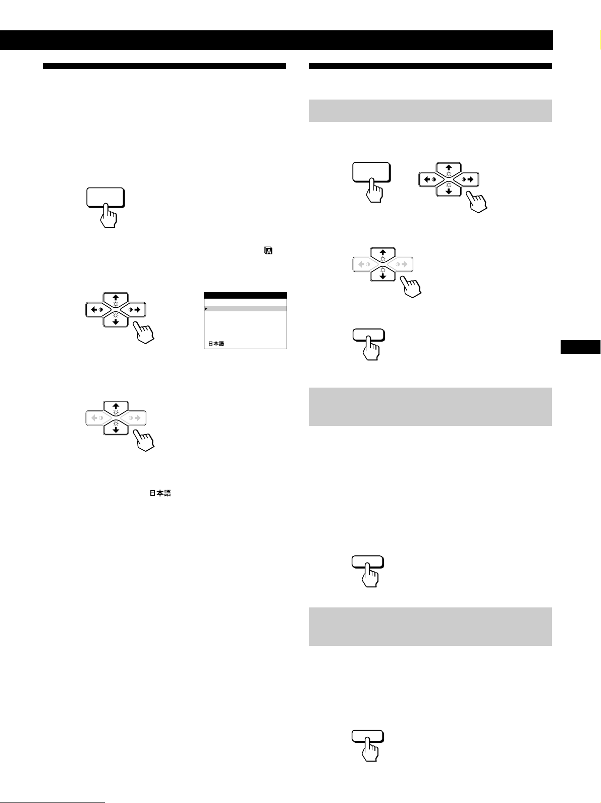
Using the LANG (Language) Onscreen Display
English, French, German, Spanish, Italian and Japanese
versions of the OSDs are available.
1 Press the MENU button.
The MENU OSD appears.
MENU
2 Press the ¨./> and >?// buttons to select “
LANG,” and press the MENU button again.
The LANGUAGE OSD appears.
LANGUAGE
ENGLISH
FRANÇAIS
DEUTSCH
ESPAÑOL
ITALIANO
3 Press the ¨./> buttons to select the desired
language.
ENGLISH: English, FRANÇAIS: French,
DEUTSCH: German, ESPAÑOL: Spanish,
ITALIANO: Italian, or
The OSD automatically disappears after about 30 seconds.
To close the OSD, press the MENU button again.
: Japanese.
Resetting the Adjustments
Resetting an adjustment item
1 Press the MENU, ¨./> and >?//buttons to select
the OSD containing the item you want to reset.
2 Press the ¨./> buttons to select the item you want
to reset.
3 Press the RESET button.
Resetting all of the adjustment data for
the current input signal
When there is no OSD displayed, press the RESET
button.
All of the adjustments data for the current input signal is
reset to the factory settings.
Note that adjustment data not affected by changes in input
signal (OSD language, OSD position, input signal selection,
power saving delay time and the control lock function) is
not reset to the factory settings.
GB
FR
DE
ES
To reset to English, press the RESET button while the OSD
is on.
Resetting all of the adjustment data for all
input signals
Press and hold the RESET button for more than two
seconds.
All of the adjustment data, including the brightness and
contrast, is reset to the factory settings.
17
Page 18

Technical Features
Technical Features
Preset and User Modes
This monitor has factory preset modes for the most popular
industry standards for true “plug and play” compatibility.
When a new input signal is entered, the monitor selects the
appropriate factory preset mode and momentarily adjusts
the phase calibration to provide a high quality picture to the
center of the screen. The calibration is stored in memory
and is immediately recalled whenever the same input signal
is received.
Resolution
(dots × lines)
No.
640 × 350
1
640 × 480
2
3
640 × 480
4
640 × 480
5
720 × 400
720 × 400
6
800 × 600
7
8
800 × 600
9
800 × 600
10
832 × 624
11
1024 × 768
1024 × 768
12
1024 × 768
13
1024 × 768
14
Horizontal
Frequency
31.5 kHz
31.5 kHz
37.5 kHz
43.3 kHz
31.5 kHz
37.9 kHz
37.9 kHz
46.9 kHz
53.7 kHz
49.7 kHz
48.4 kHz
56.5 kHz
60.0 kHz
60.2 kHz
Vertical
Frequency
70 Hz
60 Hz
75 Hz
85 Hz
70 Hz
85 Hz
60 Hz
75 Hz
85 Hz
75 Hz
60 Hz
70 Hz
75 Hz
75 Hz
Graphics Mode
MCGA
VGA-G
EVGA
VESA
VGA-Text
VESA
SVGA
ESVGA
VESA
Macintosh
16” Color
VESA
VESA
EUVGA
Macintosh
19” Color
For input signals that do not match one of the factory preset
modes, the digital Multiscan technology of this monitor
performs all of the adjustments necessary to ensure that a
clear picture appears on the screen for any timing in the
monitor’s frequency range. However, it may be necessary
to fine tune the vertical/horizontal size and centering.
Simply press the ASC button or adjust the monitor
according to the adjustment instructions. The adjustments
are stored automatically as a user mode and recalled
whenever the corresponding input signal is received.
Recommended horizontal and vertical timing
conditions
Horizontal sync width duty should be: >4.8% of total horizontal
time.
Horizontal blanking width should be: >2.8 µsec.
Vertical blanking width should be: > 450 µsec.
Note for Windows users
For Windows users, check your video board manual or the utility
program which comes with your graphic board and select the
highest available refresh rate to maximize monitor performance.
Adjusting the monitor’s resolution and color
number
Adjust the monitor’s resolution and color number by referring to
your computer’s instruction manual. The color number may vary
according to your computer or video board. The color palette
setting and the actual number of colors are as follows:
• High Color (16 bit) n 65,536 colors
• True Color (24 bit) n about 16.77 million colors
In true color mode (24 bit), speed may be slower.
15
16
17
18
19
20
21
22
23
24
25
26
18
1024 × 768
1152 × 864
1152 × 870
1280 × 960
1280 × 960
1280 × 1024
1280 × 1024
1280 × 1024
1600 × 1200
1600 × 1200
1600 × 1200
1600 × 1200
68.7 kHz
67.5 kHz
68.7 kHz
60.0 kHz
85.9 kHz
64.0 kHz
80.0 kHz
91.1 kHz
75.0 kHz
81.3 kHz
87.5 kHz
93.8 kHz
85 Hz
75 Hz
75 Hz
60 Hz
85 Hz
60 Hz
75 Hz
85 Hz
60 Hz
65 Hz
70 Hz
75 Hz
VESA
VESA
Macintosh
21” Color
VESA
VESA
VESA
VESA
VESA
VESA
VESA
VESA
VESA
Page 19
Power Saving Function
This monitor meets the power-saving guidelines set by
VESA and
NUTEK .
If the monitor is connected to a computer or video graphics
board that is VESA DPMS (Display Power Management
Signaling) compliant, the monitor will automatically reduce
power consumption in three stages as shown below.
ENERGY STAR, as well as the more stringent
Getting Started
Technical Features
You can set the delay time before the monitor enters the
power saving mode using the OSD. Set the time according
to “Setting the power saving delay time” on page 16.
Note
If no video signal is input to the monitor, the “NO INPUT
SIGNAL” message (page 20) appears. After the delay time has
passed, the power saving function automatically puts the monitor
into the active-off mode and the u indicator lights up orange. Once
the horizontal and vertical sync signals are detected, the monitor
automatically resumes its normal operation mode.
Power consumption
mode
Normal operation
1
Standby (1st mode)
2
Suspend (2nd mode)
3
Active-off (3rd mode)
4
Power-off
5
Screen
active
blank
blank
blank
—
Horizontal
sync signal
present
absent
present
absent
—
Vertical
sync signal
present
present
absent
absent
—
Displaying the Monitor’s
Information Box
You can display the model name, serial number and year of
manufacture using the monitor‘s INFORMATION OSD.
Press and hold the MENU button for 5 seconds.
The INFORMATION OSD appears.
Example:
MENU
INFORMATION
MODEL : CPD 520GST
SER NO : 1234567
MANUFACTURED
:1998 52
The INFORMATION OSD includes the model name, serial
number, manufactured year, and manufactured week.
The OSD automatically disappears after about 30 seconds.
Damper Wires
Power consumption
≤ 145 W
Approx. 72 W
Approx. 7 W
Approx. 3 W
0 W
Recovery time
—
Approx. 3 sec.
Approx. 3 sec.
Approx. 10 sec.
—
u indicator
Green
Green and orange
alternate
Green and orange
alternate
Orange
Off
Plug & Play
This monitor complies with the DDC1, DDC2B, DDC2AB
and DDC2B+ Display Data Channel (DDC) standards of
VESA.
When a DDC1 host system is connected, the monitor
synchronizes with the V. CLK in accordance with the VESA
standards and outputs the EDID (Extended Display
Identification Data) to the data line.
When a DDC2B, DDC2AB or DDC2B+ host system is
connected, the monitor automatically switches to the
appropriate standard.
DDC is a trademark of the Video Electronics Standard
Association.
Note
When using Windows 95/98, the DDC standard does not apply to
the 5 BNC connectors. If you use the DDC standard, connect the
HD15 connector to the computer with the supplied video signal
cable.
GB
FR
DE
ES
When viewing a white background, very thin horizontal lines
may be visible on the screen as shown below. These lines are
the shadows of the damper wires and are characteristic of
CRTs that use aperture grilles. The wires are attached to the
aperture grille on the inside of the Trinitron tube and prevent
the vibration of the aperture grille.
Damper wires
19
Page 20
Additional Information
Additional Information
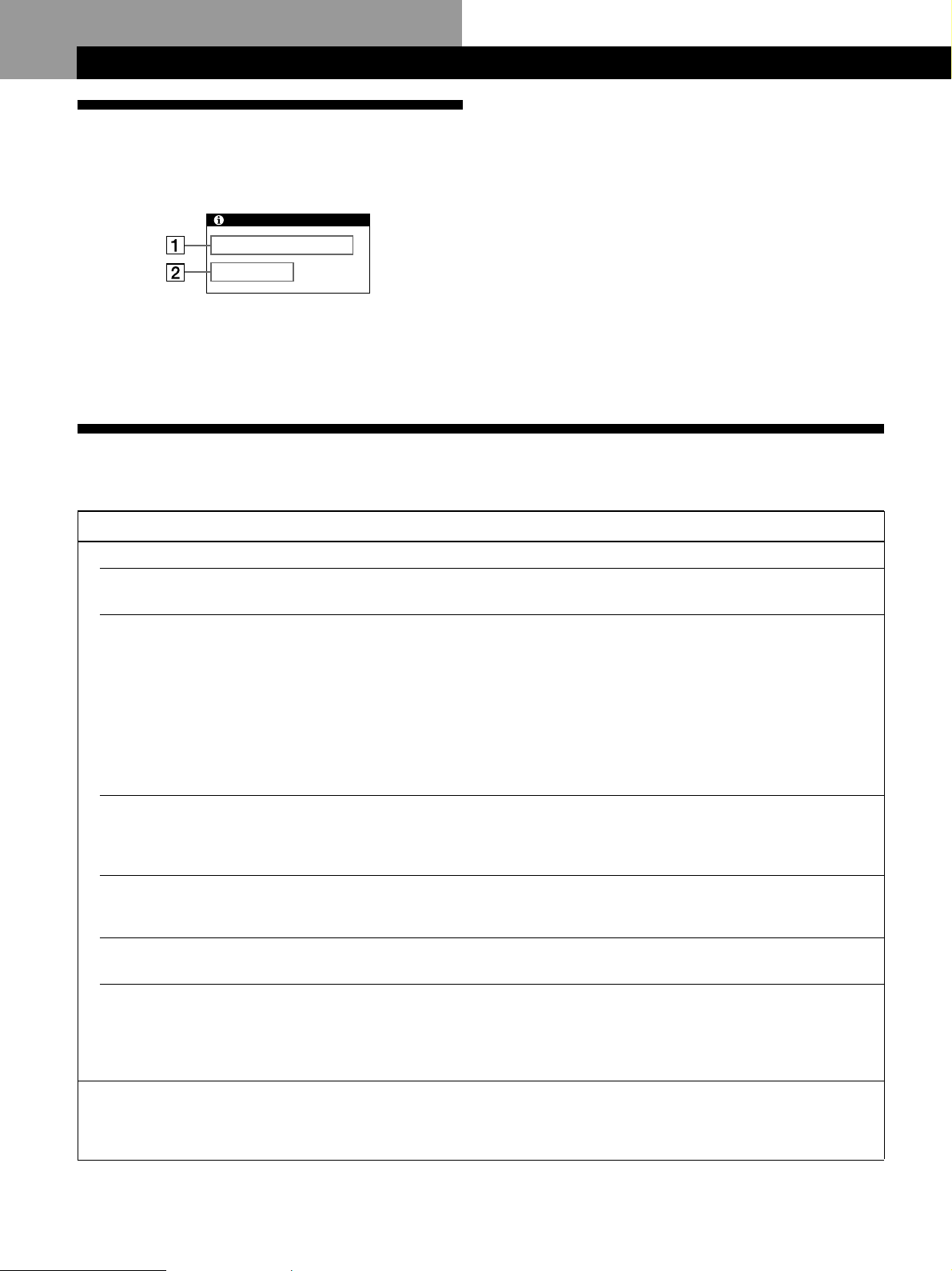
1 The input signal condition
Warning Messages
If there is something wrong with the input signal, one of the
following messages appears.
INFORMATION
OUT OF SCAN RANGE
“OUT OF SCAN RANGE” indicates that the input signal
is not supported by the monitor’s specifications.
“NO INPUT SIGNAL” indicates that no signal is input, or
the input signal from the selected input connector is not
received.
2 The selected input connector
INPUT : HD15
Indicates which input connector is receiving the wrong
signal. If there is something wrong with the signal from
both input connectors, “HD15” and “BNC” are
displayed alternately.
To solve these problems, see “Troubleshooting” below.
Troubleshooting
This section may help you isolate the cause of a problem and as a result, eliminate the need to contact technical support.
Symptom Check these items
No picture
If the u indicator is not lit
If the “NO INPUT SIGNAL”
message appears on the screen,
or if the u indicator is either
orange or alternating between
green and orange
If the “OUT OF SCAN RANGE”
message appears on the screen
If no message is displayed and
the u indicator is green or
flashing orange
If using a Macintosh system
• Check that the power cord is properly connected.
• Check that the u (power) switch is in the “on” position.
• The screen is blank when the monitor is in power saving mode. Try pressing any key on the
computer keyboard.
• Check that your computer power switch is in the “on” position.
• Check that the input select setting is correct.
• Check that the video signal cable is properly connected and all plugs are firmly seated in
their sockets.
• Check that the 5 BNCs are connected in the correct order (from left to right: Red–Green–
Blue–HD–VD) (page 6).
• Ensure that no pins are bent or pushed in the HD15 video input connector.
• Check that the video board is completely seated in the proper bus slot.
• Check that the video frequency range is within that specified for the monitor.
Horizontal: 30 – 96 kHz, Vertical: 48 – 160 Hz
Refer to your computer’s instruction manual to adjust the video frequency range.
• If you are using a video signal cable adapter, check that it is correct.
• See “Self-diagnosis Function” (page 22).
• Check that the Macintosh adapter and the video signal cable are properly connected (page
6).
If using Windows 95/98
Picture is scrambled
20
• If you replaced an old monitor with this monitor, reconnect the old monitor and do the
following. Install the Windows Monitor Information Disk (page 7) and select “CPD520GST” from among the Sony monitors in the Windows 95/98 monitor selection screen. If
you choose to select “Plug and Play,” connect the monitor to the computer with the HD15
video signal. You cannot use the five BNC connectors.
• Check your graphics board manual for the proper monitor setting.
• Check this manual and confirm that the graphics mode and the frequency you are trying to
operate at is supported. Even if the frequency is within the proper range, some video
boards may have a sync pulse that is too narrow for the monitor to sync correctly.
Page 21
Symptom Check these items
Color is not uniform
• Degauss the monitor (page 15).
If you place equipment which generates a magnetic field, such as a loudspeaker, near the
monitor, or you change the direction of the monitor, color may lose uniformity.
The degauss function demagnetizes the metal frame of the CRT to obtain a neutral field for
uniform color reproduction. If a second degauss cycle is needed, allow a minimum interval
of 20 minutes for the best result.
• Adjust the landing (pages 13 – 14).
Getting Started
Additional Information
You cannot adjust the monitor
with the buttons on the front
panel
White does not look white
Screen image is not centered or
sized properly
Edges of the image are curved
White lines show red or blue
shadows at edges
Picture is fuzzy
• If the control lock function is set to on, set it to off using the OPTION OSD (page 16).
• Adjust the color temperature (pages 12 – 13).
• Check that the 5 BNCs are connected in the correct order (from left to right: Red–Green–
Blue–HD–VD) (page 6).
• Press the ASC button (page 7).
• Adjust the size or centering (page 10).
• Some video modes do not fill the screen to the edges. This problem tends to occur with
certain video boards.
• Adjust the geometry (page 11).
• Adjust the convergence (pages 13 – 14).
• Adjust the contrast and brightness (page 9).
• Degauss the monitor (page 15).
If you place equipment which generates a magnetic field, such as a loudspeaker, near the
monitor, or you change the direction of the monitor, color may lose uniformity.
The degauss function demagnetizes the metal frame of the CRT to obtain a neutral field for
uniform color reproduction. If a second degauss cycle is needed, allow a minimum interval
of 20 minutes for the best result.
• If red or blue shadows appear along the edges of images, adjust the convergence
(pages 13 – 14).
• If the moire is cancelled, the picture may become fuzzy. Decrease the moire cancellation
effect (pages 13 – 14).
GB
FR
DE
ES
IT
Picture bounces or has wavy
oscillations
Picture is flickering
Picture appears to be ghosting
Wavy or elliptical (moire)
pattern is visible
Two fine horizontal lines
(wires) are visible
Hum is heard right after the
power is turned on
• Isolate and eliminate any potential sources of electric or magnetic fields. Common causes
for this symptom are electric fans, fluorescent lighting or laser printers.
• If you have another monitor close to this monitor, increase the distance between them to
reduce the interference.
• Try plugging the monitor into a different AC outlet, preferably on a different circuit.
• Try the monitor on a different computer in a different room.
• Set the refresh rate on the computer to obtain the best possible picture by referring to the
computer’s manual.
• Eliminate the use of video cable extensions and/or video switch boxes if this symptom
occurs. Excessive cable length or a weak connection can produce this symptom.
• Cancel the moire (pages 13 – 14).
The moire may be modified depending on the connected computer.
• Due to the relationship between resolution, monitor dot pitch and the pitch of some image
patterns, certain screen backgrounds sometimes show moire. Change your desktop pattern.
• These wires stabilize the vertically striped aperture grille (page 19). This aperture grille
allows more light to pass through to the screen giving the Trinitron CRT more color and
brightness.
• When the power is turned on, the auto-degauss cycle is activated. While the auto-degauss
cycle is activated (3 seconds), a hum may be heard. The same hum is heard when the
monitor is manually degaussed. This is not a malfunction.
21
Page 22
Additional Information
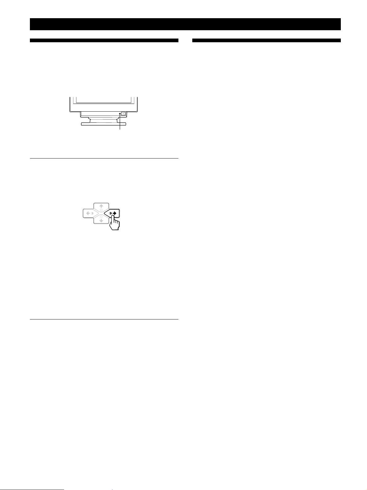
Self-diagnosis Function
This monitor is equipped with a self-diagnosis function. If
there is a problem with your monitor or computer(s), the
screen will go blank and the u indicator will either light up
green or flash orange.
u indicator
If the
1 Remove any plugs from the video input 1 and 2
2 Press and hold the >/ button for 2 seconds.
uu
u indicator is green
uu
connectors, or turn off the connected computer(s).
Specifications
Picture tube 0.25 – 0.27 mm aperture grille pitch
21 inches measured diagonally
90-degree deflection
Viewable image size Approx. 403.8 × 302.2 mm (w/h)
(16 × 12
19.8” viewing image
Resolution Horizontal: Max. 1600 dots
Vertical: Max. 1200 lines
Standard image area Approx. 388 × 291 mm (w/h)
(15
or
Approx. 364 × 291 mm (w/h)
(14
Deflection frequency Horizontal: 30 to 96 kHz
Vertical: 48 to 160 Hz
AC input voltage/current
100 to 240 V, 50 – 60 Hz, 2.0 – 1.0 A
Power consumption Max. 145 W
Dimensions 498 × 505 × 474 mm (w/h/d)
(19
Mass Approx. 31 kg (68 lb 5 oz)
Supplied accessories See page 6
inches)
3
/8 × 11 1/2 inches)
3
/8 × 11 1/2 inches)
5
/8 × 20 × 18 3/4 inches)
If all four color bars appear (white, red, green, blue), the
monitor is working properly. Reconnect the video input
cables and check the condition of your computer(s).
If the color bars do not appear, there is a potential
monitor failure. Inform your authorized Sony dealer of
the monitor’s condition.
If the
uu
u indicator is flashing orange
uu
Press the
If the u indicator lights up green, the monitor is
working properly.
If the u indicator is still flashing, there is a potential
monitor failure. Count the number of seconds between
orange flashes of the u indicator and inform your
authorized Sony dealer of the monitor’s condition. Be
sure to note the model name and serial number of your
monitor. Also note the make and model of your
computer and video board.
uu
u button to turn the monitor off and on.
uu
Design and specifications are subject to change without
notice.
22
Page 23

TABLE DES MATIERES
Préparation
Précautions ........................................................................................................................... 4
Identification des composants et des commandes.......................................................... 5
Installation ............................................................................................................................ 6
Réglage automatique de la taille et du centrage de l’image .......................................... 7
Sélection de la langue d’affichage des menus ................................................................. 7
Sélection du signal d’entrée ............................................................................................... 8
Personnalisation de l’affichage
Réglage de la luminosité et du contraste de l’image ...................................................... 9
Présentation du système d’écrans de menu..................................................................... 9
Utilisation de l’écran de menu CENTRE (centrage) ..................................................... 10
Utilisation de l’écran de menu TAILLE.......................................................................... 10
Utilisation de l’écran de menu GEOM (géométrie) ...................................................... 11
Utilisation de l’écran de menu ZOOM ........................................................................... 12
Utilisation de l’écran de menu COUL. (couleur) .......................................................... 12
Utilisation de l’écran de menu ECRAN ......................................................................... 13
Utilisation de l’écran de menu OPTION ........................................................................ 15
Utilisation de l’écran de menu LANG (langue d’affichage)........................................ 17
Réinitialisation des réglages............................................................................................. 17
FR
Caractéristiques techniques
Modes présélectionné et utilisateur ................................................................................ 18
Fonction d’économie d’énergie........................................................................................ 19
Affichage des informations sur le moniteur .................................................................. 19
Fils d’amortissement ......................................................................................................... 19
Un moniteur prêt à l’emploi (“Plug & Play”) ................................................................ 19
Informations complémentaires
Messages d’avertissement ................................................................................................ 20
Guide de dépannage ......................................................................................................... 20
Fonction d’autodiagnostic ................................................................................................ 22
Spécifications ...................................................................................................................... 22
Appendix
TCO’95 Eco-document ......................................................................................................... i
“Blue Angel” Environmental Statement ......................................................................... iii
• Macintosh est une marque de commerce de Apple Computer, Inc., déposée aux
Etats-Unis et dans d’autres pays.
• Windows et MS-DOS sont des marques de commerce de Microsoft Corporation
déposées aux Etats-Unis et dans d’autres pays.
• IBM PC/AT et VGA sont des marques de commerce de IBM Corporation déposées
aux Etats-Unis.
• VESA est une marque de commerce de Video Electronics Standard Association.
• ENERGY STAR est une marque déposée aux Etats-Unis.
• Tous les autres noms de produits mentionnés dans ce mode d’emploi sont des
marques de commerce ou des marques déposées de leur détenteurs respectifs.
• Par ailleurs, “” et “” ne sont pas repris à chaque fois dans le mode d’emploi.
3
Page 24
Préparation
Préparation
Précautions
Installation
• Veillez à assurer une circulation d’air adéquate pour
éviter une surchauffe interne de l’appareil. Ne placez pas
le moniteur sur des surfaces textiles (tapis, couvertures,
etc.) ni à proximité de rideaux ou de draperies
susceptibles d’obstruer les orifices de ventilation.
• N’installez pas le moniteur à proximité de sources de
chaleur comme un radiateur ou une bouche d’air chaud,
ni dans un endroit exposé au rayonnement solaire direct,
à des poussières en excès, à des vibrations ou à des chocs
mécaniques.
• N’installez pas le moniteur à proximité d’équipements qui
génèrent un champ magnétique tels qu’un convertisseur
ou des lignes à haute tension.
Entretien
• Nettoyez le châssis, le panneau et les commandes à l’aide
d’un chiffon doux légèrement imprégné d’une solution
détergente neutre. N’utilisez jamais de tampons abrasifs,
de poudre à récurer ou de solvants tels que de l’alcool ou
du benzine.
• Ne frottez pas, ne touchez pas et ne tapotez pas la surface
de l’écran avec des objets abrasifs ou aux arêtes vives
comme un stylo à bille ou un tournevis. Ce type de
contact risque en effet de rayer le tube image.
• Nettoyez l’écran à l’aide d’un chiffon doux. Si vous
utilisez un nettoyant liquide pour vitres, veillez à
n’utiliser aucun type de produit contenant une solution
antistatique ni d’additifs similaires, car ils risqueraient de
rayer la couche de revêtement de l’écran.
Avertissement sur le raccordement à la
source d’alimentation
• Utilisez un cordon d’alimentation convenant à votre
alimentation secteur locale.
Pour les clients au Royaume-Uni
Si vous utilisez ce moniteur au Royaume-Uni, utilisez le
cordon et la fiche pour le Royaume-Uni, utilisez le cordon
et la fiche pour le Royaume-Uni fournis.
Modèles de fiches :
pour 100 à 120 V CA pour 200 à 240 V CA pour 240 V CA
uniquement
• Avant de débrancher le cordon d’alimentation, attendez
au moins 30 secondes après avoir actionné le
commutateur d’alimentation de manière à permettre la
décharge de l’électricité statique à la surface de l’écran à
tube cathodique (CRT).
• Après que le courant a été branché, le CRT est
démagnétisé pendant environ 3 secondes. Cela génère un
puissant champ magnétique autour de l’encadrement
métallique qui peut affecter les données mémorisées sur
une bande magnétique ou des disquettes situées à
proximité. Placez ces systèmes d’enregistrement
magnétique et ces bandes/disquettes à l’écart de ce
moniteur.
La prise murale doit être installée à proximité de
l’équipement et être aisément accessible.
Transport
Pour transporter ce moniteur en vue de réparations ou de
son expédition, utilisez le carton d’emballage et les
matériaux de conditionnement d’origine.
Utilisation du support pivotant
Le support pivotant permet de régler ce moniteur suivant
l’angle de vision de votre préférence dans une plage de 180°
horizontalement et 20° verticalement.
Pour faire pivoter le moniteur verticalement et
horizontalement, maintenez-le des deux mains par la base
comme illustré ci-dessous.
15°
90°
90°
5°
4
Page 25
Identification des composants et
des commandes
Pour plus de détails, reportez-vous aux pages indiquées
entre parenthèses.
Préparation
Partie frontale
1 Touche RESET (réinitialisation) (page 17)
Réinitialise les réglages aux valeurs par défaut.
2 Touche ASC (taille et centrage
automatiques) (page 7)
Ajuste automatiquement la taille et le centrage des
images.
3 Touche INPUT (entrée) et indicateurs HD15/
BNC (page 8)
Sélectionne le signal d’entrée vidéo HD15 ou 5BNC.
Chaque fois que vous appuyez sur cette touche, le
signal d’entrée et l’indicateur correspondant alternent.
4 Touche MENU (menu) (pages 8 – 17, 19)
Affiche l’écran MENU.
5 Touches > (contraste) (?//) (pages 8 – 17,
22)
Règlent le contraste de l’image.
Servent de touches (?//) pour le réglage d’autres
paramètres.
6 Touches ¨ (luminosité) (./>) (pages 8 – 17)
Règlent la luminosité de l’image.
Servent de touches (./>) pour le réglage d’autres
paramètres.
Partie arrière
8 Connecteur AC IN
Assure l’alimentation du moniteur.
9 Connecteur d’entrée vidéo 1 (HD15)
Entrée des signaux vidéo RVB (0,700 Vcc, positif) et des
signaux SYNC.
5 4 3 2
Broche n°
1
2
3
4
5
6
7
8
* Norme Display Data Channel (DDC) de VESA
Signal
Rouge
Vert
(synchronisation
composite
sur le vert)
Bleu
ID (Masse)
Masse DDC*
Masse rouge
Masse vert
Masse bleu
1
678910
1112131415
Broche n°
9
10
11
12
13
14
15
Signal
DDC + 5V*
Masse
ID (Masse)
Données
bidirectionnelles
(SDA)*
Sync H
Sync V
Données
d’horloge
(SCL)*
FR
7 Commutateur et indicateur d’alimentation
u (pages 19, 22)
Met le moniteur sous et hors tension.
L’indicateur s’allume en vert lorsque le moniteur est
sous tension et clignote en vert et orange ou s’allume en
orange lorsque le moniteur se trouve en mode
d’économie d’énergie.
!º Connecteur d’entrée vidéo 2 (5 BNC)
Entrée des signaux vidéo RVB (0,700 Vcc, positif) et des
signaux SYNC.
5
Page 26
Préparation
Installation
Avant de mettre ce moniteur en service, vérifiez si tous les
accessoires suivants se trouvent bien dans le carton :
• Moniteur (1)
• Cordon d’alimentation (1)
• Câble de signal vidéo HD15 (1)
• Adaptateur Macintosh (1)
• Windows Monitor Information Disk (1)
• Carte de garantie (1)
• Remarques sur l’entretien de la surface de l’écran (1)
• Ce mode d’emploi (1)
Ce moniteur fonctionne avec n’importe quel système IBM
ou compatible doté d’une capacité graphique VGA ou
supérieure. Bien que ce moniteur fonctionne avec d’autres
plates-formes tournant à des fréquences horizontales
comprises entre 30 et 96 kHz, y compris des systèmes
Macintosh et Power Macintosh, un adaptateur de câble est
nécessaire. Veuillez consulter votre revendeur pour des
conseils sur l’adaptateur correspondant à vos besoins.
1re étape: Raccordez le moniteur à
l’ordinateur
L’ordinateur étant hors tension, raccordez le câble de signal
vidéo HD15 fourni au moniteur.
• Si vous utilisez un PC/AT IBM ou un ordinateur
compatible, reportez-vous à la section ci-dessous.
• Si vous utilisez un Macintosh ou un ordinateur
compatible, reportez-vous à la section “Raccordement à
un Macintosh ou un ordinateur compatible” ci-après.
• Si vous voulez utiliser les 5 connecteurs BNC, reportezvous à la section “Raccordement aux 5 connecteurs BNC”
ci-après.
Si votre système PC n’est pas compatible avec
DDC2AB et DDC2B+
Ce moniteur utilise la broche n° 9 du connecteur de signal vidéo
pour la compatibilité avec DDC2AB et DDC2B+.
Il se peut que certains systèmes PC, qui ne sont pas compatibles
avec DDC2AB ou DDC2B+, n’acceptent pas la broche n° 9. Si vous
n’êtes pas sûr que votre système PC accepte la broche n° 9, utilisez
un adaptateur HD15 (femelle) - HD15 (mâle sans la broche n° 9)
(non fourni). Branchez le côté mâle (sans la broche n° 9) sur
l’ordinateur.
Raccordement à un Macintosh ou un ordinateur
compatible
vers HD15
Macintosh ou
ordinateur
compatible
vers la sortie vidéo
Adaptateur
Macintosh (fourni)
Câble de
signal vidéo
HD15 (fourni)
A propos de l’adaptateur Macintosh fourni
L’adaptateur Macintosh fourni est compatible avec les ordinateurs
Macintosh LC, Performa, Quadra, Power Macintosh et Power
Macintosh G3.
Il se peut que les ordinateurs Macintosh II et certaines anciennes
versions de Power Book requièrent un adaptateur doté de
microcommutateurs (non fourni).
Raccordement aux 5 connecteurs BNC
Raccordement à un PC/AT IBM ou à un
ordinateur compatible
vers HD15
PC/AT IBM ou
ordinateur
compatible
* L’adaptateur HD15 - HD15 peut être nécessaire pour certains
modèles.
vers la sortie vidéo
Adaptateur HD15 HD15 (non fourni)*
Câble de
signal vidéo
HD15 (fourni)
6
vers VIDEO IN R/G/B vers SYNC IN
Raccordez-le à l’ordinateur
comme pour le connecteur
HD15.
HD/VD
Pour raccorder les 5 connecteurs BNC, utilisez le câble de
signal vidéo SMF-400 (vendu séparément). Raccordez les
câbles de la gauche vers la droite dans l’ordre suivant :
Rouge-Vert-Bleu-HD-VD.
Remarques
• Ne court-circuitez pas les broches du câble de signal vidéo.
• La norme DDC ne s’applique pas aux 5 connecteurs BNC. Si
vous utilisez la norme DDC, raccordez le connecteur HD15 à
l’ordinateur à l’aide du câble de signal vidéo fourni.
Page 27
Préparation
2e étape: Branchez le cordon
d’alimentation
Le moniteur étant hors tension, branchez le cordon
d’alimentation au moniteur et l’autre extrémité à une prise
murale.
vers une prise
murale
Cordon d’alimentation (fourni)
vers AC IN
3e étape: Mettez le moniteur et
l’ordinateur sous tension
L’installation de votre moniteur est à présent terminée.
Remarque
Si le message “HORS PLAGE DE BALAYAGE” ou “PAS ENTREE
VIDEO” apparaît à l’écran, voir “Messages d’avertissement” à la
page 20.
Pour les clients utilisant Windows 95/98
Pour maximaliser le potentiel de votre moniteur, installez sur votre
ordinateur le nouveau fichier d’informations modèle depuis la
disquette “Windows Monitor Information Disk”.
Ce moniteur est conforme à la norme Plug & Play “VESA DDC”. Si
votre PC/carte graphique est conforme à la norme DDC,
sélectionnez “Plug & Play Monitor (VESA DDC)” ou la désignation
de ce moniteur comme type de moniteur dans le “Control Panel”
sous Windows 95/98. Si votre PC/carte graphique a des difficultés
à communiquer avec ce moniteur, chargez la disquette “Windows
Monitor Information Disk” et sélectionnez la désignation de ce
moniteur comme type de moniteur.
Pour les utilisateurs de Windows NT4.0
L’installation du moniteur sous Windows NT4.0 est différente de
celle sous Windows 95/98 et n’implique pas la sélection du type de
moniteur. Reportez-vous au mode d’emploi de Windows NT4.0
pour plus de détails sur le réglage de la résolution, le taux de
régénération et le nombre de couleurs.
Réglage automatique de la taille
et du centrage de l’image
Une pression sur la touche (ASC) permet de régler
automatiquement la taille et le centrage de l’image pour
l’adapter à l’écran.
1 Mettez le moniteur et l’ordinateur sous tension.
2 Appuyez sur la touche ASC.
L’image est ajustée pour s’adapter au centre de l’écran.
ASC
Remarques
• Cette fonction est prévue pour une utilisation sous Windows ou
avec un logiciel à interface graphique similaire qui fournit une
image plein écran. Il se peut qu’elle ne fonctionne pas
correctement si la couleur d’arrière-plan est sombre ou si l’image
d’entrée ne remplit pas l’écran jusqu’aux bords (telle que l’invite
du MS-DOS).
• Il se peut que l’écran devienne blanc pendant quelques secondes
lorsque vous exécutez la fonction de réglage automatique de la
taille. Il ne s’agit pas d’un dysfonctionnement.
• Bien que les signaux du rapport d’image 5:4 (résolution:
1280␣ ×␣ 1024) ne remplissent pas l’écran jusqu’aux bords, l’image
est affichée de manière précise.
Sélection de la langue
d’affichage des menus
Pour changer la langue d’affichage des écrans de menu, voir
la section “Utilisation de l’écran de menu LANG (langue
d’affichage)” à la page 17.
Le réglage par défaut est l’anglais.
FR
7
Page 28
Préparation
OUI
DEGAUSS MANUEL
DEVERR
1 MIN
OPTION
ZZ...
AUTO
ZZ...
ENTREE
1 MIN
OPTION
DEVERR
MANUEL
Sélection du signal d’entrée
Ce moniteur est doté de deux connecteurs d’entrée de signal
(HD15 et 5BNC) et peut être raccordé à deux ordinateurs.
Lorsque les deux ordinateurs sont sous tension, sélectionnez
le signal que vous voulez visualiser selon la procédure
suivante.
1 Mettez le moniteur et les deux ordinateurs sous
tension.
2 Appuyez sur les touches ¨./> et >?// pour
sélectionner “
la touche MENU.
L’écran OPTION apparaît.
OPTION” et appuyez à nouveau sur
2 Appuyez sur la touche INPUT pour sélectionner le
signal d’entrée HD15 ou 5BNC.
Chaque fois que vous appuyez sur la touche INPUT, le
signal d’entrée et l’indicateur correspondant alternent.
HD15 BNC
INPUT
Sélection du mode de signal d’entrée
Ce moniteur a deux modes de sélection du signal d’entrée,
“AUTO” et “MANUEL”.
Si “AUTO” est sélectionné
Si aucun signal n’est entré via le connecteur sélectionné, le
moniteur sélectionne automatiquement le signal de l’autre
connecteur. Si vous redémarrez l’ordinateur que vous
voulez utiliser ou si cet ordinateur se trouve en mode
d’économie d’énergie, il se peut que le moniteur sélectionne
automatiquement le signal de l’autre connecteur. La raison
en est que le moniteur est passé du signal interrompu au
signal constant. Si cela se produit, sélectionnez
manuellement le signal voulu à l’aide de la touche INPUT.
3 Appuyez sur les touches ¨./> pour sélectionner
“
(ENTREE)”.
4 Appuyez sur les touches >?// pour sélectionner
“AUTO” ou “MANUEL”.
L’écran OPTION disparaît automatiquement au bout
d’environ 30 secondes.
Pour désactiver l’écran de menu, appuyez à nouveau sur la
touche MENU.
Pour plus de détails sur l’utilisation des écrans de menu, voir
“Présentation du système d’écrans de menu” à la page 9.
Si “MANUEL” est sélectionné
Même si aucun signal n’est entré via le connecteur
sélectionné, le moniteur ne sélectionne pas le signal de
l’autre connecteur.
1 Appuyez sur la touche MENU.
L’écran MENU apparaît.
MENU
LANG
CENTRE
QUITTE
TAILLE
MENU
COUL.
GEOM
8
OK
ECRAN
ZOOM
OPTION
MENU
Page 29
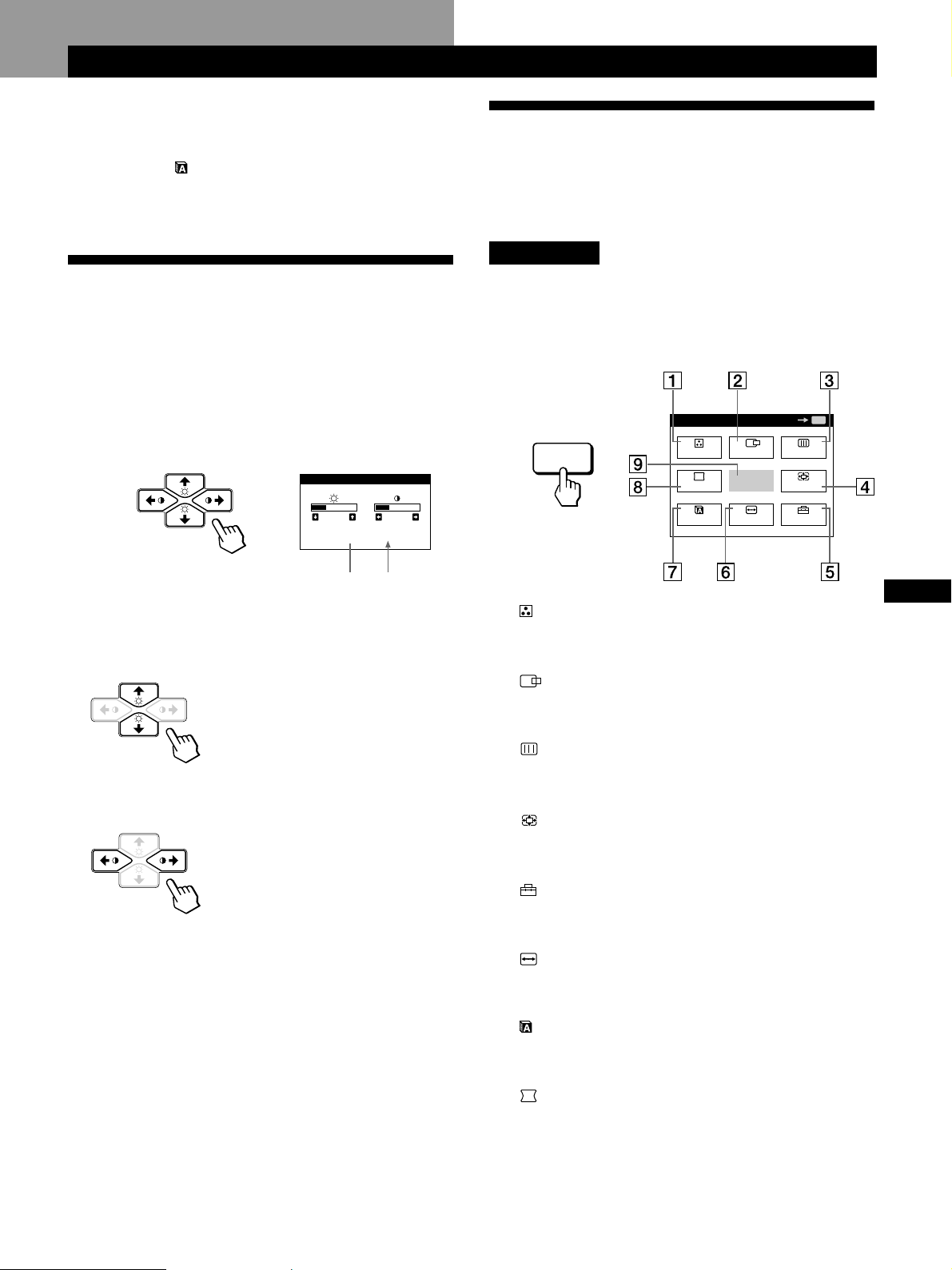
MENU
MENU
QUITTE
CENTRE
TAILLE
GEOM
COUL.
LANG
ZOOM
ECRAN
OPTION
OK
MENU
Personnalisation de l’affichage
Avant le réglage
• Raccordez le moniteur et l’ordinateur et mettez-les sous
tension.
• Sélectionnez “
sélectionnez ensuite “FRANÇAIS” (voir page 17).
LANG” dans l’écran MENU et
Personnalisation de l’affichage
Présentation du système d’écrans
de menu
La plupart des réglages sont effectués à l’aide de l’écran de
menu MENU.
Ecran MENU
Réglage de la luminosité et du
contraste de l’image
Une fois le réglage effectué, il sera conservé en mémoire
pour tous les signaux d’entrée reçus.
1 Appuyez sur les touches ¨ (luminosité) ./> ou
> (contraste) ?//.
L’écran LUMINOSITE/CONTRASTE apparaît.
LUMINOSITE/CONTRASTE
26 26
80.0kHz/ 75Hz
Fréquence
horizontale*
2 Pour le réglage de la luminosité
Appuyez sur les touches ¨./>.
> . . . pour augmenter la luminosité
. . . . pour diminuer la luminosité
Pour le réglage du contraste
Appuyez sur les touches >?// .
/ . . . pour augmenter le contraste
? . . . pour diminuer le contraste
L’écran de menu disparaît automatiquement au bout
d’environ 3 secondes.
Pour réinitialiser les valeurs de réglage, appuyez sur la
touche RESET pendant que l’écran est affiché.
La luminosité et le contraste sont tous deux ramenés aux
valeurs de réglage par défaut.
* Les fréquences horizontale et verticale pour le signal d’entrée
reçu apparaissent dans l’écran de menu LUMINOSITE/
CONTRASTE.
Fréquence
verticale*
Appuyez sur la touche MENU pour afficher l’écran
MENU.
Cet écran MENU contient des liens avec les autres écrans de
menu décrits ci-dessous.
FR
1 COUL.
Affiche l’écran de menu COULEUR pour le réglage de
la température des couleurs.
2 CENTRE
Affiche l’écran de menu CENTRAGE pour le réglage du
centrage de l’image.
3 ECRAN
Affiche l’écran de menu ECRAN pour le réglage de la
convergence verticale et horizontale, etc.
4 ZOOM
Affiche l’écran de menu ZOOM pour agrandir et
réduire la taille de l’image.
5 OPTION
Affiche l’écran de menu OPTION pour ajuster la
position de l’écran de menu et démagnétiser l’écran, etc.
6 TAILLE
Affiche l’écran de menu TAILLE pour le réglage de la
taille de l’image.
7 LANG
Affiche l’écran de menu LANGUAGE pour sélectionner
la langue d’affichage.
8 GEOM
Affiche l’écran de menu GEOMETRIE pour régler la
rotation et la distorsion en coussin de l’image, etc.
9 QUITTE
Referme l’écran MENU.
9
Page 30
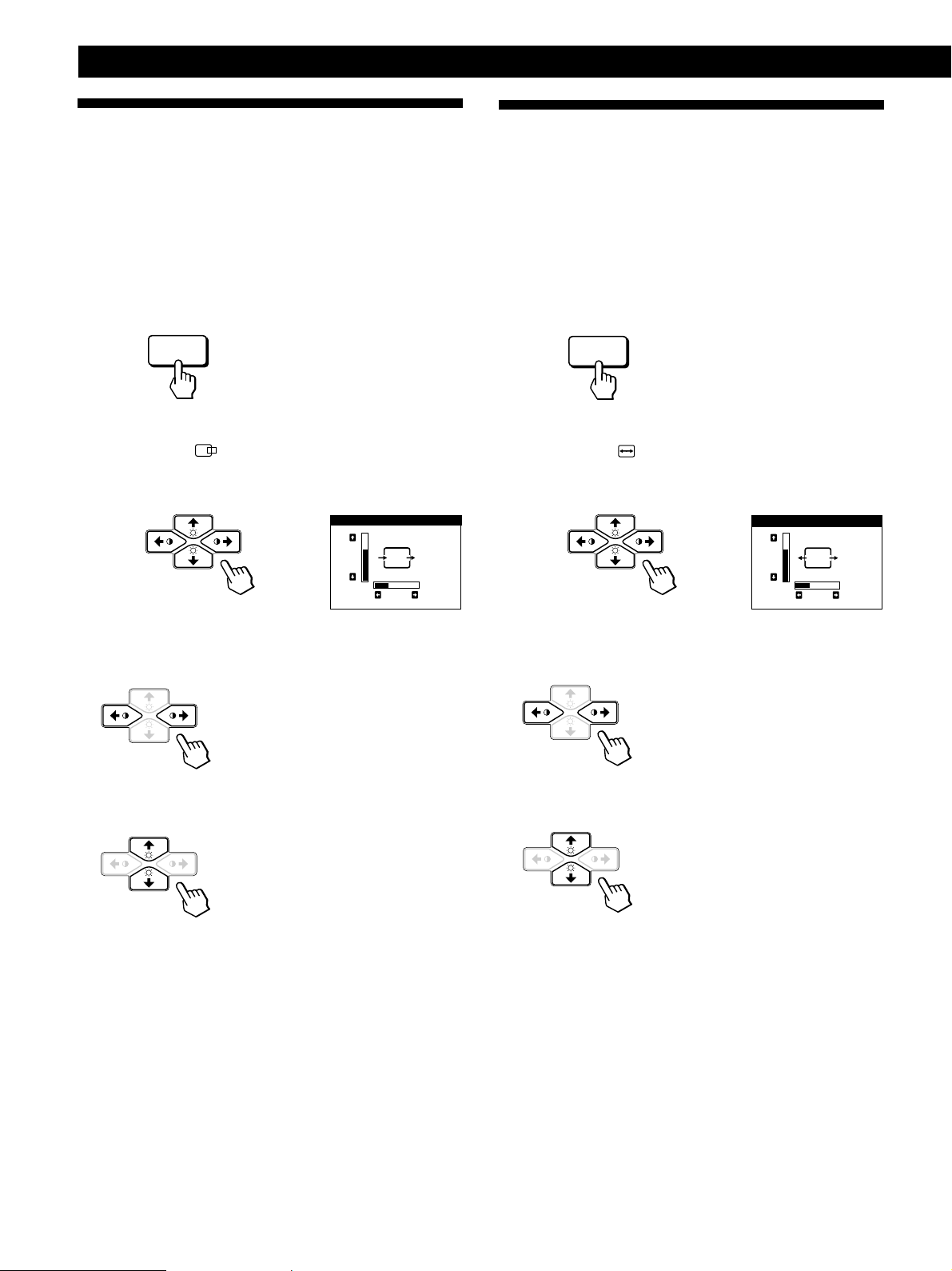
Personnalisation de l’affichage
Utilisation de l’écran de menu
CENTRE (centrage)
Les réglages CENTRE vous permettent d’ajuster le centrage
de l’image.
Une fois que le réglage est effectué, il sera conservé en
mémoire pour le signal d’entrée en cours.
1 Appuyez sur la touche MENU.
L’écran MENU apparaît.
MENU
2 Appuyez sur les touches ¨./> et >?// pour
sélectionner “
nouveau sur la touche MENU.
L’écran de menu CENTRAGE apparaît.
CENTRE” et appuyez ensuite à
CENTRAGE
73
Utilisation de l’écran de menu
TAILLE
Les réglages TAILLE vous permettent d’ajuster la taille de
l’image.
Une fois que le réglage est effectué, il sera conservé en
mémoire pour le signal d’entrée en cours.
1 Appuyez sur la touche MENU.
L’écran MENU apparaît.
MENU
2 Appuyez sur les touches ¨./> et >?// pour
sélectionner “
nouveau sur la touche MENU.
L’écran de menu TAILLE apparaît.
TAILLE” et appuyez ensuite à
TAILLE
73
26
3 Pour le réglage horizontal
Appuyez sur les touches >?//.
/ . . . pour déplacer l’image vers la
droite
? . . . pour déplacer l’image vers la
gauche
Pour le réglage vertical
Appuyez sur les touches ¨./>.
> . . . pour déplacer l’image vers le
haut
. . . . pour déplacer l’image vers le
bas
L’écran de menu disparaît automatiquement au bout
d’environ 30 secondes.
Pour refermer l’écran de menu, appuyez à nouveau sur la
touche MENU.
Pour réinitialiser les valeurs de réglage, appuyez sur la
touche RESET pendant que l’écran est affiché.
Les centrages horizontal et vertical sont tous deux ramenés
aux valeurs de réglage par défaut.
26
3 Pour le réglage horizontal
Appuyez sur les touches >?//.
/ . . . pour augmenter la taille de
l’image
? . . . pour réduire la taille de l’image
Pour le réglage vertical
Appuyez sur les touches ¨./>.
> . . . pour augmenter la taille de
l’image
. . . . pour réduire la taille de l’image
L’écran de menu disparaît automatiquement au bout
d’environ 30 secondes.
Pour refermer l’écran de menu, appuyez à nouveau sur la
touche MENU.
Pour réinitialiser les valeurs de réglage, appuyez sur la
touche RESET pendant que l’écran est affiché.
Les tailles horizontale et verticale sont toutes deux ramenées
aux valeurs de réglage par défaut.
10
Page 31

Utilisation de l’écran de menu
GEOM (géométrie)
Les réglages GEOM (géométrie) vous permettent d’ajuster
la forme et l’orientation de l’image.
Une fois que la rotation est réglée, elle sera conservée en
mémoire pour tous les signaux d’entrée reçus. Tous les
autres réglages seront mémorisés pour le signal d’entrée en
cours.
1 Appuyez sur la touche MENU.
L’écran MENU apparaît.
MENU
Personnalisation de l’affichage
4
Appuyez sur les touches >?// pour ajuster les
réglages.
Pour
ROTATION
Appuyez sur
/ . . . pour faire pivoter l’image dans le
sens horaire
? . . . pour faire pivoter l’image dans le sens
antihoraire
2 Appuyez sur les touches ¨./> et >?// pour
sélectionner “
nouveau sur la touche MENU.
L’écran GEOMETRIE apparaît.
GEOM” et appuyez ensuite à
GEOMETRIE
26
ROTATION
3 Appuyez sur les touches ¨./> pour sélectionner le
paramètre que vous voulez régler.
Sélectionnez
ROTATION
COUSSIN
CORR CYL
Pour
régler la rotation de l’image
régler les côtés de l’image
régler la correction cylindrique de
l’image
COUSSIN
CORR CYL
TRAPEZE
CORR PARAL
/ . . . pour élargir les côtés de l’image
? . . . pour resserrer les côtés de l’image
/ . . . pour déplacer les côtés de l’image
vers la droite
? . . . pour déplacer les côtés de l’image
vers la gauche
/ . . . pour augmenter la largeur de
l’image dans le haut
? . . . pour diminuer la largeur de l’image
dans le haut
/ . . . pour déplacer le haut de l’image
vers la droite
? . . . pour déplacer le haut de l’image vers
la gauche
FR
TRAPEZE
CORR PARAL
régler la largeur de l’image
régler l’inclinaison de l’image
L’écran de menu disparaît automatiquement au bout
d’environ 30 secondes.
Pour refermer l’écran de menu, appuyez à nouveau sur la
touche MENU.
Pour réinitialiser les valeurs de réglage, appuyez sur la
touche RESET pendant que l’écran est affiché.
Le paramètre sélectionné est ramené à la valeur de réglage
par défaut.
11
Page 32

Personnalisation de l’affichage
MENU
5000K 6500K 9300K
V
COULEUR
50
R
50
B
50
Utilisation de l’écran de menu
ZOOM
Les réglages ZOOM vous permettent d’agrandir ou de
réduire l’image.
Une fois que le réglage est effectué, il sera conservé en
mémoire pour le signal d’entrée en cours.
1 Appuyez sur la touche MENU.
L’écran MENU apparaît.
MENU
2 Appuyez sur les touches ¨./> et >?// pour
sélectionner “
nouveau sur la touche MENU.
L’écran de menu ZOOM apparaît.
ZOOM” et appuyez ensuite à
ZOOM
Utilisation de l’écran de menu
COUL. (couleur)
Vous pouvez modifier la température de couleur du
moniteur. Par exemple, vous pouvez régler ou modifier les
couleurs d’une image à l’écran pour qu’elles correspondent
aux couleurs réelles de l’image imprimée.
Une fois le réglage effectué, il sera conservé en mémoire
pour tous les signaux d’entrée reçus.
1 Appuyez sur la touche MENU.
L’écran MENU apparaît.
2 Appuyez sur les touches ¨./> et >?// pour
sélectionner “
nouveau sur la touche MENU.
L’écran de menu COULEUR apparaît.
26H
73V
COUL.” et appuyez ensuite à
3 Appuyez sur les touches >?// pour régler le zoom
sur l’image.
/ . . . pour agrandir l’image
? . . . pour réduire l’image
L’écran de menu disparaît automatiquement au bout
d’environ 30 secondes.
Pour refermer l’écran de menu, appuyez à nouveau sur la
touche MENU.
Pour réinitialiser les valeurs de réglage, appuyez sur la
touche RESET pendant que l’écran est affiché.
Remarque
Le zoom sur l’image s’arrête dès que la taille horizontale ou
verticale atteint sa valeur maximum ou minimum.
3 Appuyez sur les touches >?// pour sélectionner la
température des couleurs.
L’écran de menu propose trois modes de température
des couleurs.
Les réglages par défaut sont :
5000K, 6500K, 9300K
12
Page 33

MENU
4 Réglage fin de la température de couleur
Appuyez sur les touches ¨./> pour sélectionner R
(rouge), V (vert) ou B (bleu) et procédez au réglage en
appuyant sur les touches >?//.
Personnalisation de l’affichage
Utilisation de l’écran de menu
ECRAN
COULEUR
1 6500K 9300K
R
V
B
76
50
50
L’indication “5000K”, “6500K” ou “9300K” disparaît et
les nouveaux réglages des couleurs sont mémorisés pour
chacun des trois modes de couleur.
Les modes de température changent comme suit:
5000Kn 1, 6500Kn 2, 9300Kn 3
L’écran de menu disparaît automatiquement après environ
30 secondes.
Pour faire disparaître l’écran de menu, appuyez de nouveau
sur la touche MENU.
Pour réinitialiser, appuyez sur la touche RESET lorsque
l’écran de menu apparaît. Le paramètre sélectionné est
réinitialisé aux valeurs par défaut définies en usine.
Vous pouvez régler les valeurs de convergence pour
éliminer les ombres rouge et bleue qui pourraient apparaître
autour des objets de l’écran. Réglez la fonction ELIM
MOIRAGE pour éliminer les motifs ondulatoires ou
elliptiques qui pourraient apparaître à l’écran.
Réglez la fonction PURETE COULEUR pour corriger les
irrégularités de couleurs dans les quatre coins de l’écran
dues à l’influence du magnétisme terrestre.
Une fois que ELIM MOIRAGE est réglé, il sera mémorisé
pour le signal d’entrée en cours. Tous les autres réglages
seront mémorisés pour tous les signaux d’entrée reçus.
1 Appuyez sur la touche MENU.
L’écran de menu MENU apparaît.
2 Appuyez sur les touches ¨./> et >?// pour
sélectionner “
nouveau sur la touche MENU.
L’écran de menu ECRAN apparaît.
ECRAN” et appuyez ensuite à
FR
ECRAN
TOP
BOT
ADJ
26
CONVERGENCE H
3 Appuyez sur les touches ¨./> pour sélectionner le
paramètre à régler.
Sélectionnez
CONVERGENCE H
CONVERGENCE V
TOP
CONVER V HAUT
Pour
régler la convergence horizontale
régler la convergence verticale
régler la convergence verticale dans
le haut de l’écran
BOT
CONVER V BAS
régler la convergence verticale dans
le bas de l’écran
(suite)
13
Page 34

Personnalisation de l’affichage
Sélectionnez
PURETE COULEUR
ADJ
PURETE COULEUR
ELIM MOIRAGE*
ADJ
REGLAGE MOIRE
* Le moiré est un type d’interférence naturelle qui produit des
lignes douces ou ondulatoires sur votre écran. Il peut apparaître
en raison des interférences entre le motif régulé du signal
d’entrée et le motif phosphorisé du TRC.
Exemple de moiré:
Pour
sélectionner l’un des quatre coins
nécessitant la correction de couleur
en raison de l’influence du
magnétisme terrestre.
corriger la couleur dans l’un des
quatre coins de l’écran
activer (“OUI”) ou désactiver
(“NON”) l’annulation de moiré.
ELIM MOIRAGE doit être réglé sur
“OUI” pour que “ ADJ
(REGLAGE MOIRE)” apparaisse à
l’écran.
régler le degré d’annulation de moiré
Pour
TOP
CONVER V HAUT
BOT
CONVER V BAS
PURETE COULEUR
ADJ
PURETE COULEUR
Appuyez sur
/ . . . pour décaler les ombres rouges vers le
haut et les ombres bleues vers le bas
? . . . pour décaler les ombres rouges vers le
bas et les ombres bleues vers le haut
/ . . . pour décaler les ombres rouges vers le
haut et les ombres bleues vers le bas
? . . . pour décaler les ombres rouges vers le
bas et les ombres bleues vers le haut
/ ou ? . . . pour sélectionner le coin de
l’écran que vous désirez régler
: en haut à gauche : en haut à droite
: en bas à gauche : en bas à droite
/ ou ? . . .pour réduire au minimum les
irrégularités dans la couleur
4 Appuyez sur les touches >?// pour ajuster les
réglages.
Pour
CONVERGENCE H
CONVERGENCE V
Appuyez sur
/ . . .pour décaler les ombres rouges vers la
droite et les ombres bleues vers la
gauche
? . . .pour décaler les ombres rouges vers la
gauche et les ombres bleues vers la
droite
/ . . . pour décaler les ombres rouges vers le
haut et les ombres bleues vers le bas
? . . . pour décaler les ombres rouges vers le
bas et les ombres bleues vers le haut
50
/ . . . pour activer ELIM MOIRAGE (“OUI”)
ELIM MOIRAGE
ADJ
REGLAGE MOIRE
? . . . pour désactiver ELIM MOIRAGE
(“NON”)
/ ou ? . . .pour régler l’écran jusqu’à ce
OUI
NON
OUI
NON
que le moiré est au minimum
50
Remarque
Il se peut que l’image devienne floue lorsque ELIM MOIRAGE est
réglé sur “OUI”.
L’écran de menu disparaît automatiquement au bout
d’environ 30 secondes.
Pour refermer l’écran de menu, appuyez à nouveau sur la
touche MENU.
Pour réinitialiser les valeurs de réglage, appuyez sur la
touche RESET pendant que l’écran est affiché.
Le paramètre sélectionné est ramené à la valeur de réglage
par défaut.
14
Page 35

Personnalisation de l’affichage
MENU
Utilisation de l’écran de menu
OPTION
L’écran de menu OPTION vous permet de démagnétiser
manuellement l’écran et d’ajuster les réglages tels que la
position des écrans de menu et le délai d’activation du
mode d’économie d’énergie. Il vous permet également de
verrouiller la commande.
Démagnétisation de l’écran
L’écran du moniteur est automatiquement démagnétisé à la
mise sous tension.
Vous pouvez aussi démagnétiser manuellement l’écran.
1 Appuyez sur la touche MENU.
L’écran MENU apparaît.
MENU
2 Appuyez sur les touches ¨./> et >?// pour
sélectionner “
nouveau sur la touche MENU.
L’écran de menu OPTION apparaît.
3 Appuyez sur les touches ¨./> pour sélectionner
“
(DEGAUSS MANUEL)”.
OPTION” et appuyez ensuite à
OPTION
OUI
ZZ...
1 MIN
DEVERR
DEGAUSS MANUEL
Changement de la position d’affichage des
écrans de menu
Vous pouvez changer la position d’affichage des écrans de
menu (par exemple, lorsque vous voulez régler l’image
derrière un écran de menu).
1 Appuyez sur la touche MENU.
L’écran MENU apparaît.
2 Appuyez sur les touches ¨./> et >?// pour
sélectionner “
nouveau sur la touche MENU.
L’écran de menu OPTION apparaît.
OPTION” et appuyez ensuite à
OPTION
OUI
ZZ...
1 MIN
DEVERR
DEGAUSS MANUEL
3 Appuyez sur les touches ¨./> pour sélectionner
“
(POSITION OSD H)” ou “ (POSITION OSD V)”.
Sélectionnez “
position horizontale.
(POSITION OSD H)” pour ajuster la
OPTION
ZZ...
1 MIN
DEVERR
POSITION OSD H
GB
FR
DE
ES
IT
4 Appuyez sur la touche > /.
L’écran est démagnétisé pendant environ 3 secondes.
Si vous devez démagnétiser l’écran une seconde fois,
attendez au moins 20 minutes avant de répéter cette
procédure.
L’écran de menu OPTION disparaît automatiquement au
bout d’environ 30 secondes.
Pour refermer l’écran de menu, appuyez à nouveau sur la
touche MENU.
Sélectionnez “
(POSITION OSD V)” pour ajuster la
position verticale.
OPTION
AUTO
ZZ...
DEVERR
POSITION OSD V
4 Appuyez sur les touches >?// pour amener l’écran
de menu à la position voulue.
L’écran de menu OPTION disparaît automatiquement au
bout d’environ 30 secondes.
Pour refermer l’écran de menu, appuyez à nouveau sur la
touche MENU.
Pour réinitialiser les valeurs de réglage, appuyez sur la
touche RESET pendant que l’écran est affiché.
15
Page 36

Personnalisation de l’affichage
MENU
Réglage du délai d’activation du mode
d’économie d’énergie
Vous pouvez définir le délai au terme duquel le moniteur
passe en mode d’économie d’énergie. Voir page 19 pour des
informations plus détaillées sur les capacités d’économie
d’énergie de ce moniteur.
1 Appuyez sur la touche MENU.
L’écran MENU apparaît.
MENU
2 Appuyez sur les touches ¨./> et >?// pour
sélectionner “
nouveau sur la touche MENU.
L’écran de menu OPTION apparaît.
OPTION” et appuyez ensuite à
OPTION
OUI
ZZ...
1 MIN
DEVERR
DEGAUSS MANUEL
Verrouillage des commandes
La fonction de verrouillage des commandes désactive toutes
les touches du panneau frontal à l’exception du
commutateur d’alimentation u et la touche MENU.
1 Appuyez sur la touche MENU.
L’écran MENU apparaît.
2 Appuyez sur les touches ¨./> et >?// pour
sélectionner “
nouveau sur la touche MENU.
L’écran de menu OPTION apparaît.
OPTION” et appuyez ensuite à
OPTION
OUI
ZZ...
1 MIN
DEVERR
DEGAUSS MANUEL
3 Appuyez sur les touches ¨./> pour sélectionner
(VERROU REGLAGES)”.
“
OPTION
3 Appuyez sur les touches ¨./> pour sélectionner
ZZ...
“
(ECONOMIE TEMPO)”.
OPTION
AUTO
5 SEC
60 MIN
1 MIN
NON
ZZ...
ECONOMIE TEMPO
4 Appuyez sur les touches >?// pour sélectionner le
délai voulu.
Lorsque ECONOMIE TEMPO est réglé sur “NON”, le
moniteur ne passe pas en mode d’économie d’énergie.
L’écran de menu OPTION disparaît automatiquement au
bout d’environ 30 secondes.
Pour refermer l’écran de menu, appuyez à nouveau sur la
touche MENU.
Pour réinitialiser les valeurs de réglage, appuyez sur la
touche RESET pendant que l’écran est affiché.
AUTO
ZZ...
DEVERR VERR
VERROU REGLAGES
4 Appuyez sur les touches >?// pour sélectionner
“VERR”.
L’écran de menu OPTION disparaît automatiquement au
bout d’environ 30 secondes.
Pour refermer l’écran de menu, appuyez à nouveau sur la
touche MENU.
Lorsque vous avez sélectionné “VERR”, vous ne pouvez
plus sélectionner aucun paramètre à l’exception de
“QUITTE” et “
Si vous appuyez sur une touche autre que le commutateur
d’alimentation u ou la touche MENU, l’indication
apparaît à l’écran.
Pour désactiver le verrouillage des commandes
Répétez les étapes 1 à 3 ci-dessus et appuyez sur les touches
>?// pour sélectionner “DEVERR”.
OPTION” dans l’écran MENU.
16
Page 37

Personnalisation de l’affichage
MENU
RESET
RESET
RESET
Utilisation de l’écran de menu
LANG (langue d’affichage)
Vous avez le choix entre l’allemand, l’anglais, l’espagnol, le
français, l’italien et le japonais pour l’affichage des menus.
1 Appuyez sur la touche MENU.
L’écran MENU apparaît.
MENU
2 Appuyez sur les touches ¨./> et >?// pour
sélectionner “
nouveau sur la touche MENU.
L’écran de menu LANGUAGE apparaît.
LANG” et appuyez ensuite à
LANGUAGE
ENGLISH
FRANÇAIS
DEUTSCH
ESPAÑOL
ITALIANO
Réinitialisation des réglages
Réinitialisation d’un paramètre
1 Appuyez sur les touches MENU, ¨./> et >?//
pour sélectionner l’écran de menu contenant le
paramètre que vous voulez réinitialiser.
2 Appuyez sur les touches ¨./> pour sélectionner le
paramètre que vous voulez réinitialiser.
3 Appuyez sur la touche RESET.
GB
3 Appuyez sur les touches ¨./> pour sélectionner la
langue d’affichage de votre choix.
ENGLISH : anglais, FRANÇAIS : français,
DEUTSCH : allemand, ESPAÑOL : espagnol,
ITALIANO: italien, ou :
L’écran de menu disparaît automatiquement au bout
d’environ 30 secondes. Pour refermer l’écran de menu,
appuyez à nouveau sur la touche MENU.
Pour réinitialiser les valeurs de réglage, appuyez sur la
touche RESET pendant que l’écran est affiché.
japonais.
Réinitialisation de toutes les données de
réglage pour le signal d’entrée en cours
Alors qu’aucun écran de menu n’est affiché, appuyez sur
la touche RESET.
Toutes les données de réglage pour le signal d’entrée en
cours sont ramenées aux valeurs de réglage par défaut.
Attention que les données de réglage qui ne sont pas
affectées par les changements du signal d’entrée (langue et
position d’affichage des écrans de menu, sélection du signal
d’entrée, délai d’activation du mode d’économie d’énergie
et fonction de verrouillage des commandes) ne sont pas
ramenées aux valeurs de réglage par défaut.
Réinitialisation de toutes les données de
réglage pour tous les signaux d’entrée
FR
DE
ES
IT
Maintenez la touche RESET enfoncée pendant au moins
deux secondes.
Toutes les données de réglage, y compris la luminosité et le
contraste, sont ramenées aux valeurs de réglage par défaut.
17
Page 38

Caractéristiques techniques
Caractéristiques techniques
Modes présélectionné et
utilisateur
Ce moniteur est présélectionné pour les modes de
fonctionnement les plus fréquemment utilisés de manière à
garantir une vraie compatibilité “Plug & Play”.
Lorsqu’un nouveau signal d’entrée est reçu, le moniteur
sélectionne le mode de présélection d’usine et ajuste
momentanément le calibrage de phase pour fournir une
image de haute qualité au centre de l’image. Le calibrage est
mémorisé et est immédiatement rappelé chaque fois que le
même signal d’entrée est reçu.
Résolution
(points × lignes)
N°
1
640 × 350
2
640 × 480
3
640 × 480
4
640 × 480
5
720 × 400
6
720 × 400
7
800 × 600
8
800 × 600
9
800 × 600
10
832 × 624
11
1024 × 768
12
1024 × 768
13
1024 × 768
14
1024 × 768
15
1024 × 768
16
1152 × 864
17
1152 × 870
18
1280 × 960
19
1280 × 960
20
1280 × 1024
21
1280 × 1024
22
1280 × 1024
23
1600 × 1200
24
1600 × 1200
25
1600 × 1200
26
1600 × 1200
Fréquence
horizontale
31,5 kHz
31,5 kHz
37,5 kHz
43,3 kHz
31,5 kHz
37,9 kHz
37,9 kHz
46,9 kHz
53,7 kHz
49,7 kHz
48,4 kHz
56,5 kHz
60,0 kHz
60,2 kHz
68,7 kHz
67,5 kHz
68,7 kHz
60,0 kHz
85,9 kHz
64,0 kHz
80,0 kHz
91,1 kHz
75,0 kHz
81,3 kHz
87,5 kHz
93,8 kHz
Fréquence
verticale
70 Hz
60 Hz
75 Hz
85 Hz
70 Hz
85 Hz
60 Hz
75 Hz
85 Hz
75 Hz
60 Hz
70 Hz
75 Hz
75 Hz
85 Hz
75 Hz
75 Hz
60 Hz
85 Hz
60 Hz
75 Hz
85 Hz
60 Hz
65 Hz
70 Hz
75 Hz
Mode graphique
MCGA
VGA-G
EVGA
VESA
VGA-Text
VESA
SVGA
ESVGA
VESA
Macintosh
16” couleur
VESA
VESA
EUVGA
Macintosh
19” couleur
VESA
VESA
Macintosh
21” couleur
VESA
VESA
VESA
VESA
VESA
VESA
VESA
VESA
VESA
Pour les signaux d’entrée qui ne correspondent pas à l’un
des modes présélectionnés, la technologie numérique
Multiscan de ce moniteur effectue tous les réglages
nécessaires pour veiller à ce qu’une image claire apparaisse
à l’écran pour n’importe quelle synchronisation dans sa
plage de fréquences. Toutefois, il se peut que vous deviez
effectuer le réglage fin de la taille horizontale/verticale et le
centrage. Appuyez simplement sur la touche ASC ou réglez
le moniteur en fonction des instructions de réglage. Les
réglages sont conservés automatiquement comme mode
utilisateur et sont rappelés chaque fois qu’un signal
correspondant est reçu.
Conditions de synchronisation horizontale et
verticale préconisées
La largeur de synchronisation horizontale doit être de : > 4,8% de la
durée horizontale totale.
La largeur de neutralisation horizontale doit être de : > 2,8 µs.
La largeur de neutralisation verticale doit être de : > 450 µs.
Remarque pour les utilisateurs Windows
Vérifiez le mode d’emploi de votre carte vidéo ou le programme
utilitaire fourni avec la carte graphique et sélectionnez le taux de
régénération le plus élevé de manière à maximiser les performances
du moniteur.
Réglage de la résolution du moniteur et du nombre
de couleurs
Ajustez la résolution du moniteur et le nombre de couleurs en vous
référant au mode d’emploi de votre ordinateur. Le nombre de
couleurs peut varier selon votre ordinateur ou votre carte vidéo. Le
réglage de la palette de couleurs et le nombre réel de couleurs se
présentent comme suit:
• High Color (16 bit) n 65.536 couleurs
• True Color (24 bit) n environ 16,77 millions de couleurs
En mode True Color (24 bit), la vitesse peut être inférieure.
18
Page 39

Fonction d’économie d’énergie
Ce moniteur répond aux directives d’économie d’énergie
établies par VESA et
sévères de NUTEK.
Si le moniteur est raccordé à un ordinateur ou à une carte
graphique vidéo compatible VESA DPMS (Display Power
Management Signaling), le moniteur réduira automatiquement
la consommation de courant en trois étapes, comme indiqué cidessous.
ENERGY STAR, ainsi qu’aux normes plus
Caractéristiques techniques
Vous pouvez définir le délai au terme duquel le moniteur passe
en mode d’économie d’énergie à l’aide des écrans de menu.
Définissez cette durée conformément à la procédure de
“Réglage du délai d’activation du mode d’économie d’énergie”
à la page 16.
Remarque
Si aucun signal vidéo n’est entré sur le moniteur, le message “PAS
ENTREE VIDEO” (page 20) apparaît. Lorsque le délai est écoulé, la
fonction d’économie d’énergie fait automatiquement passer le
moniteur en mode inactif et l’indicateur u s’allume en orange.
Lorsque les signaux de synchronisation horizontale et verticale sont
détectés, le moniteur repasse automatiquement en mode de
fonctionnement normal.
Mode de
consommation
d’énergie
1
Fonctionnement
normal
2
Veille
(1er mode)
3
Interruption
(2e␣ mode)
4
Inactif
(3e mode)
5
Hors tension
Ecran
actif
inactif
inactif
inactif
—
Horizontal signal de
synchro
présent
absent
présent
absent
—
Vertical
signal de synchro
présent
présent
absent
absent
—
Affichage des informations sur le
moniteur
Vous pouvez afficher la désignation du modèle, le numéro de
série et l’année de fabrication à l’aide de l’écran
INFORMATIONS du moniteur.
Maintenez la touche MENU enfoncée pendant 5 secondes.
L’écran INFORMATIONS apparaît.
Exemple:
MENU
L’écran INFORMATIONS mentionne la désignation du modèle,
le numéro de série et l’année et la semaìne de fabrication.
L’écran disparaît automatiquement au bout de 30 secondes.
INFORMATIONS
MODEL : CPD 520GST
SER NO : 1234567
MANUFACTURED
:1998 52
Consommation
électrique
≤ 145 W
Approx. 72 W
Approx. 7 W
Approx. 3 W
0 W
Temps de
reprise
—
Approx.
3 s
Approx.
3 s
Approx.
10 s
—
Indicateur u
Vert
Vert et orange en
alternance
Vert et orange en
alternance
Orange
Désactivé
Un moniteur prêt à l’emploi
(“Plug & Play”)
Ce moniteur satisfait aux normes Display Data Channel (DDC)
DDC1, DDC2B, DDC2AB et DDC2B+ de VESA.
Si un serveur DDC1 est raccordé, le moniteur se synchronise
sur V. CLK conformément aux normes VESA et sort l’EDID
(Extended Display Identification Data) vers la ligne de données.
Si un serveur DDC2B, DDC2AB ou DDC2B+ est raccordé, le
moniteur commute automatiquement sur la norme appropriée.
DDC est une marque déposée de Video Electronics Standard
Association.
Remarque
Si vous utilisez Windows 95/98, la norme DDC ne s’applique pas
aux 5 connecteurs BNC. Si vous utilisez la norme DDC, raccordez le
connecteur HD15 à l’ordinateur au moyen du câble de signal vidéo
fourni.
FR
Fils d’amortissement
Sur un fond blanc, il se peut que vous observiez sur l’écran de
très fines lignes horizontales comme illustré ci-dessous. Il s’agit
des ombres des fils d’amortissement. Ce phénomène est
typique pour les tubes cathodiques, qui utilisent des grilles
d’ouverture. Les fils d’amortissement sont fixés à la grille
d’ouverture à l’intérieur du tube Trinitron de façon à amortir
les vibrations de la grille d’ouverture.
Fils d’amortissement
19
Page 40

Informations complémentaires
Informations complémentaires
1 Condition du signal d’entrée
Messages d’avertissement
Lorsqu’une anomalie du signal d’entrée est détectée, l’un
des messages suivants apparaît.
INFORMATIONS
HORS PLAGE DE BALAYAGE
ENTREE : HD15
”HORS PLAGE DE BALAYAGE” indique que le signal
d’entrée n’est pas supporté par les spécifications du
moniteur.
”PAS ENTREE VIDEO” indique qu’aucun signal n’est
entré ou que le signal entré via le connecteur d’entrée
sélectionné n’est pas reçu.
2 Le connecteur d’entrée sélectionné
Indique quel connecteur d’entrée reçoit le signal erroné.
Si une anomalie se produit avec le signal transmis via
les deux connecteurs d’entrée, “HD15” et “BNC”
s’affichent alternativement.
Pour remédier à ces problèmes, reportez-vous à la section
de “Guide de dépannage” ci-dessous.
Guide de dépannage
Cette section peut vous aider à localiser un problème et, par conséquent, vous éviter de consulter un service technique.
Symptôme Vérifiez
Pas d’image
Si l’indicateur u n’est pas
allumé
Si le message “PAS ENTREE
VIDEO” apparaît à l’écran ou
si l’indicateur u est orange ou
passe alternativement de
l’orange au vert
Si le message “HORS PLAGE
DE BALAYAGE” apparaît à
l’écran
Si aucun message n’est affiché
et si l’indicateur u est vert ou
clignote en orange
Si vous utilisez un système
Macintosh.
Si vous utilisez Windows 95/
98
L’image est brouillée.
• Vérifiez si le cordon d’alimentation est correctement branché.
• Vérifiez que l’interrupteur u (alimentation) est réglé sur la position “on”.
• L’écran est vide lorsque le moniteur est en mode d’économie d’énergie. Appuyez sur
une touche quelconque du clavier de l’ordinateur.
• Vérifiez si l’interrupteur d’alimentation de votre ordinateur est réglé sur la position “on”.
• Vérifiez si le réglage de la sélection d’entrée est correct.
• Vérifiez si le câble de signal vidéo est correctement branché et si toutes les fiches sont
fermement enfoncées dans les prises.
• Vérifiez si les 5 BNC sont connectés dans le bon ordre (de gauche à droite : Rouge–
Vert–Bleu–HD–VD) (page 6).
• Assurez-vous qu’aucune broche n’est pliée ou enfoncée dans le connecteur d’entrée
vidéo HD15.
• Vérifiez si la carte vidéo est correctement enfoncée dans la fente de bus adéquate.
• Vérifiez si la plage de fréquence vidéo correspond à la plage spécifiée pour le moniteur.
Horizontale : 30 – 96 kHz, Verticale : 48 – 160 Hz
Reportez-vous au mode d’emploi de votre ordinateur pour régler la plage de fréquence
vidéo.
• Si vous utilisez un adaptateur de câble de signal vidéo, vérifiez s’il est correct.
• Voir “Fonction d’autodiagnostic” (page 22).
• Vérifiez si l’adaptateur Macintosh et le câble de signal vidéo sont correctement branchés
(page 6).
• Si vous remplacez un ancien moniteur par ce moniteur, reconnectez l’ancien moniteur
et procédez comme suit. Installez la disquette “Windows Monitor Information Disk”
(page 7) et sélectionnez “CPD-520GST” parmi les moniteurs Sony dans l’écran de
sélection de moniteur de Windows 95/98. Si vous choisissez de sélectionner “Plug &
Play”, connectez le moniteur à l’ordinateur à l’aide du câble de signal vidéo HD15.
Vous ne pouvez pas utiliser les cinq connecteurs BNC.
• Consultez le mode d’emploi de votre carte graphique pour le réglage approprié du
moniteur.
• Consultez ce mode d’emploi et vérifiez si le mode graphique et la fréquence que vous
essayez d’utiliser sont supportés. Même si la fréquence est comprise dans la plage
requise, certaines cartes vidéo peuvent avoir une impulsion de synchronisation trop
étroite pour une synchronisation correcte du moniteur.
20
Page 41

Symptôme Vérifiez
Les couleurs ne sont pas
uniformes
Vous ne parvenez pas à régler
le moniteur à l’aide des
touches du panneau frontal
Le blanc n’est pas blanc
L’image à l’écran n’est pas
centrée ou dimensionnée
correctement
Les bords de l’image sont
incurvés
Le rebord des lignes blanches
est ombré de rouge ou de
bleu
L’image est floue
L’image sautille ou oscille
fortement
• Démagnétisez le moniteur (page 15).
Si vous placez près du moniteur un appareil qui génère un champ magnétique comme
un haut-parleur ou si vous changez l’orientation du moniteur, il est possible que les
couleurs perdent leur uniformité. Cette fonction sert à démagnétiser le cadre
métallique du tube cathodique de façon à obtenir un champ neutre pour une
reproduction uniforme des couleurs. Si un second cycle de démagnétisation est
nécessaire, laissez s’écouler un intervalle d’au moins 20 minutes pour obtenir les
meilleurs résultats.
• Réglez “Pureté couleur” (pages 13 – 14 ).
• Si la fonction de verrouillage des commandes est activée, désactivez-la dans le menu
OPTION (page 16).
• Réglez la température des couleurs (pages 12 - 13).
• Vérifiez si les 5 BNC sont connectés dans le bon ordre (de gauche à droite : Rouge–
Vert–Bleu–HD–VD) (page 6).
• Appuyez sur la touche ASC (page 7).
• Réglez le centrage ou la taille de l’image (page 10).
• Certains modes vidéo ne remplissent pas l’écran jusqu’aux bords. Ce problème a
tendance à se manifester avec certaines cartes vidéo.
• Réglez la géométrie (page 11).
• Réglez la convergence (pages 13 – 14).
• Réglez le contraste et la luminosité (page 9).
• Démagnétisez le moniteur (page 15).
Si vous placez près du moniteur un appareil qui génère un champ magnétique comme
un haut-parleur ou si vous changez l’orientation du moniteur, il est possible que les
couleurs perdent leur uniformité.
Cette fonction sert à démagnétiser le cadre métallique du tube cathodique de façon à
obtenir un champ neutre pour une reproduction uniforme des couleurs. Si un second
cycle de démagnétisation est nécessaire, laissez s’écouler un intervalle d’au moins 20
minutes pour obtenir les meilleurs résultats.
• Si le contour des images est ombré de bleu ou de rouge, procédez au réglage de la
convergence (pages 13 – 14).
• Lorsque le moiré a été supprimé, il arrive que l’image devienne floue. Réduisez l’effet
de suppression du moiré (pages 13 – 14).
• Isolez et éliminez toute source potentielle de champs électriques ou magnétiques. C’est
généralement le cas des ventilateurs électriques, des éclairages fluorescents, des
imprimantes laser.
• Si un autre moniteur se trouve à proximité de celui-ci, éloignez-les de façon à réduire
les interférences.
• Branchez le moniteur sur une autre prise d’alimentation, de préférence sur un circuit
différent.
• Essayez le moniteur sur un ordinateur différent dans une autre pièce.
Informations complémentaires
FR
L’image scintille
Apparition d’images
fantômes
Apparition d’un motif
ondulatoire ou elliptique
(moiré)
Deux fines lignes horizontales
(fils) sont visibles
Un souffle est audible juste
après la mise sous tension
• Réglez le taux de régénération de l’ordinateur pour obtenir la meilleure image possible
en vous référant au mode d’emploi de l’ordinateur.
• Si ce symptôme se manifeste, débranchez les câbles prolongateurs vidéo et/ou les
boîtiers de commutation vidéo. Une longueur de câble excessive ou des connexions
lâches peuvent être à l’origine de l’apparition de ce symptôme.
• Supprimez le moiré (pages 13 – 14).
Le moiré peut varier suivant l’ordinateur connecté.
• Suivant le rapport entre la résolution, le pas des points du moniteur et le pas de
certaines trames d’image, il arrive que des arrière-plans présentent un effet de moiré.
Cet effet de moiré ne peut être éliminé qu’en changeant le motif de votre bureau.
• Ces fils stabilisent la grille d’ouverture rayée verticalement (page 19). Cette grille
permet le passage d’une plus grande quantité de lumière dans l’écran, assurant ainsi
au tube cathodique Trinitron des couleurs et une luminosité plus éclatantes.
• Le cycle de démagnétisation est activé à la mise sous tension. Pendant que le cycle de
démagnétisation est activé, un souffle peut se faire entendre. Ce même souffle est
audible lors de la démagnétisation manuelle. Il ne s’agit pas d’un dysfonctionnement.
21
Page 42

Informations complémentaires
Fonction d’autodiagnostic
Ce moniteur est doté d’une fonction d’autodiagnostic. S’il y
a un problème avec votre moniteur ou ordinateur(s), l’écran
devient blanc et l’indicateur u s’allume en vert ou clignote
en orange.
Indicateur u
Si l’indicateur
1 Débranchez les fiches des connecteurs d’entrée vidéo
1 et 2 ou mettez l’ordinateur raccordé hors tension.
2 Appuyez sur la touche >/ et maintenez-la enfoncée
pendant 2 secondes.
uu
u est vert
uu
Spécifications
Tube image Pas d’ouverture de grille de
0,25 – 0,27 mm
21 pouces mesurés en diagonale
Déflexion de 90 degrés
Taille de l’image affichée
Approx. 403,8 × 302,2 mm (l/h)
Zone de visualisation de 19,8”
Résolution Horizontale : Max. 1600 points
Verticale : Max. 1200 lignes
Zone d’image standard Approx. 388 × 291 mm (l/h)
ou
Approx. 364 × 291 mm (l/h)
Fréquence de déflexion Horizontale : 30 à 96 kHz
Verticale : 48 à 160 Hz
Tension/courant CA d’entrée
100 à 240 V, 50 – 60 Hz, 2,0 – 1,0 A
Consommation électrique
Max. 145 W
Dimensions 498 × 505 × 474 mm (l/h/p)
Masse Approx. 31 kg
Accessoires fournis Voir page 6
La conception et les spécifications sont sujettes à
modifications sans préavis.
Si les quatre barres de couleur apparaissent (blanc,
rouge, vert et bleu), c’est que le moniteur fonctionne
correctement. Rebranchez les câbles d’entrée vidéo et
vérifiez l’état de votre (vos) ordinateur(s).
Si les barres de couleur n’apparaissent pas, c’est qu’il y a
une défaillance potentielle du moniteur. Informez votre
revendeur Sony agréé de l’état du moniteur.
Si l’indicateur
Appuyez sur la touche
hors et puis à nouveau sous tension.
Si l’indicateur u apparaît en vert, c’est que le moniteur
fonctionne correctement.
Si l’indicateur u clignote toujours, c’est qu’il y a une
défaillance potentielle du moniteur. Comptez le nombre
de secondes entre les clignotements oranges de
l’indicateur u et informez votre revendeur Sony agréé
de l’état du moniteur. N’oubliez pas de relever la
désignation de modèle et le numéro de série de votre
moniteur. Notez également la marque et le modèle de
votre ordinateur et de votre carte vidéo.
uu
u clignote en orange
uu
uu
u pour mettre le moniteur
uu
22
Page 43

INHALT
Vorbereitungen
Sicherheitsmaßnahmen ....................................................................................................... 4
Lage und Funktion der Teile und Bedienelemente ........................................................ 5
Anschließen des Geräts ....................................................................................................... 6
Automatisches Einstellen der Größe und Zentrierung des Bildes ............................... 7
Auswählen der Sprache für die Bildschirmanzeigen ..................................................... 7
Auswählen des Eingangssignals ....................................................................................... 8
Einstellen des Monitors
Einstellen von Bildhelligkeit und Kontrast ...................................................................... 9
Das Bildschirmmenüsystem............................................................................................... 9
Die Bildschirmanzeige BILDLG (Bildlage) .................................................................... 10
Die Bildschirmanzeige GRÖSSE...................................................................................... 10
Die Bildschirmanzeige GEOM (Geometrie)................................................................... 11
Die Bildschirmanzeige ZOOM ........................................................................................ 12
Die Bildschirmanzeige FARBE ........................................................................................ 12
Die Bildschirmanzeige BILD ............................................................................................ 13
Die Bildschirmanzeige OPTION ..................................................................................... 15
Die Bildschirmanzeige LANG (Sprache)........................................................................ 17
Zurücksetzen der Einstellungen...................................................................................... 17
Technische Merkmale
Vordefinierte Modi und Benutzermodi.......................................................................... 18
Energiesparfunktion.......................................................................................................... 19
Anzeigen der Monitorinformationen ............................................................................. 19
Dämpfungsdrähte.............................................................................................................. 19
Plug & Play ......................................................................................................................... 19
Weitere Informationen
Warnmeldungen ................................................................................................................ 20
Störungsbehebung ............................................................................................................. 20
Selbstdiagnosefunktion ..................................................................................................... 22
Technische Daten ............................................................................................................... 22
Appendix
TCO’95 Eco-document ......................................................................................................... i
Erläuterungen zum Umweltschutz (“Blauer Engel”).................................................... iv
• Macintosh ist ein Warenzeichen der Apple Computer, Inc., in den USA und
anderen Ländern.
• Windows® und MS-DOS sind eingetragene Warenzeichen der Microsoft
Corporation in den USA und anderen Ländern.
• IBM PC/AT und VGA sind eingetragene Warenzeichen der IBM Corporation in
den USA.
• VESA ist ein Warenzeichen der Video Electronics Standard Association.
• ENERGY STAR ist ein eingetragenes Warenzeichen in den USA.
• Alle anderen in diesem Handbuch erwähnten Produktnamen können
Warenzeichen oder eingetragene Warenzeichen der jeweiligen Eigentümer sein.
• Im Handbuch sind die Warenzeichen und eingetragenen Warenzeichen nicht
ausdrücklich durch „™“ bzw. „®“ gekennzeichnet.
DE
3
Page 44

Vorbereitungen
Vorbereitungen
Sicherheitsmaßnahmen
Aufstellung
• Achten Sie auf ausreichende Luftzufuhr, damit sich im
Monitor kein Wärmestau bildet. Stellen Sie den Monitor
nicht auf Oberflächen wie Teppichen oder Decken oder in
der Nähe von Materialien wie Gardinen und
Wandbehängen auf, die die Lüftungsöffnungen
blockieren könnten.
• Stellen Sie den Monitor nicht in der Nähe von
Wärmequellen wie Heizkörpern oder Warmluftauslässen
oder an Orten auf, an denen er direktem Sonnenlicht,
außergewöhnlich viel Staub, mechanischen Vibrationen
oder Stößen ausgesetzt ist.
• Stellen Sie den Monitor nicht in der Nähe anderer Geräte
auf, die ein starkes Magnetfeld generieren, wie zum
Beispiel ein Transformator oder eine
Hochspannungsleitung.
Wartung
• Reinigen Sie Gehäuse, Bedienfeld und Bedienelemente
mit einem weichen Tuch, das Sie leicht mit einem milden
Reinigungsmittel angefeuchtet haben. Verwenden Sie
keine Scheuermittel, Scheuerschwämme oder
Lösungsmittel wie Alkohol oder Benzin.
• Berühren Sie die Bildschirmoberfläche nicht mit scharfen,
rauhen oder spitzen Gegenständen wie zum Beispiel
Kugelschreibern oder Schraubenziehern. Andernfalls
könnte die Bildschirmoberfläche zerkratzt werden.
• Reinigen Sie den Bildschirm mit einem weichen Tuch.
Wenn Sie ein Glasreinigungsmittel verwenden, achten Sie
darauf, daß es keine Antistatik-Lösung oder ähnliche
Zusätze enthält, da diese zu Kratzern auf der
Beschichtung des Bildschirms führen könnten.
Warnhinweis zum Netzanschluß
• Verwenden Sie das für die Stromversorgung in Ihrem
Land geeignete Netzkabel.
Für Kunden in Großbritannien
Wenn Sie den Monitor in Großbritannien verwenden,
benutzen Sie bitte das mitgelieferte Kabel mit dem für
Großbritannien geeigneten Stecker.
Beispiele für Steckertypen
für 100 bis 120 V
Wechselstrom
• Warten Sie nach dem Ausschalten des Geräts mindestens
30 Sekunden, bevor Sie das Netzkabel lösen. In dieser Zeit
kann sich die statische Elektrizität auf der Oberfläche der
Kathodenstrahlröhre entladen.
• Wenn Sie das Gerät einschalten, wird die
Kathodenstrahlröhre etwa 3 Sekunden lang
entmagnetisiert. Dadurch entsteht um den Metallrand der
Röhre ein starkes magnetisches Feld, das Daten auf
Magnetbändern oder anderen Datenträgern in der Nähe
beschädigen kann. Legen Sie magnetische Datenträger
und Bänder/Disketten daher nicht zu nahe bei diesem
Monitor ab.
Die Netzsteckdose sollte sich in der Nähe des Geräts
befinden und leicht zugänglich sein.
für 200 bis 240 V
Wechselstrom
nur für 240 V
Wechselstrom
Transport
Wenn Sie den Monitor einmal transportieren müssen,
verpacken Sie ihn wieder mit Hilfe der
Originalverpackungsmaterialien im Originalkarton.
Der dreh- und neigbare Ständer
Mit dem dreh- und neigbaren Ständer können Sie den
Monitor so einstellen, wie es Ihnen angenehm ist. Dabei
können Sie ihn horizontal um bis zu 180° drehen und
vertikal um bis zu 20° neigen.
Wenn Sie den Monitor drehen oder neigen, stützen Sie ihn
bitte mit beiden Händen unten ab, wie auf der Abbildung
unten gezeigt.
15°
90°
90°
5°
4
Page 45

Lage und Funktion der Teile und
Bedienelemente
Weitere Informationen finden Sie auf den in Klammern
angegebenen Seiten.
Vorbereitungen
Vorderseite
1 Rücksetztaste RESET (Seite 17)
Zum Zurücksetzen der Werte auf die werkseitigen
Einstellungen.
2 Taste ASC (Größe/Zentrierung automatisch
einstellen) (Seite 7)
Zum automatischen Einstellen der Größe und
Zentrierung der Bilder.
3 Taste INPUT (Eingang) und HD15/BNC-
Anzeigen (Seite 8)
Zum Auswählen des HD15- oder 5BNCVideoeingangssignals. Mit jedem Tastendruck wechseln
das Eingangssignal und die entsprechende Anzeige.
4 Taste MENU (Menü) (Seite 8 – 17, 19)
Zum Aufrufen der Bildschirmanzeige MENU.
5 Tasten > (Kontrast) (?//) (Seite 8 – 17,
22)
Zum Einstellen des Kontrasts.
Darüber hinaus werden auch andere Optionen mit den
Tasten (?//) eingestellt.
6 Tasten ¨ (Helligkeit) (./>) (Seite 8 – 17)
Zum Einstellen der Bildhelligkeit.
Rückseite
8 Netzeingang AC IN
Zur Stromversorgung des Monitors.
9 Videoeingang 1 (HD15)
Zum Einspeisen von RGB-Videosignalen (0,700 Vp-p,
positiv) und SYNC-Signalen.
5 4 3 2
Stift Nr.
1
2
3
4
5
6
7
* DDC-Standard (DDC = Display Data Channel) nach VESA
Signal
Rot
Grün
zusammengesetztes
(
Grünsignal mit
Synchronisation)
Blau
ID (Masse)
DDC-Masse*
Masse Rot
Masse Grün
1
1112131415
Stift Nr.
8
9
10
11
12
13
14
15
678910
Signal
Masse Blau
DDC + 5V*
Masse
ID (Masse)
Bidirektionale
Daten (SDA)*
H. Sync
V. Sync
Datentakt (SCL)*
DE
Darüber hinaus werden auch andere Optionen mit den
Tasten (./>) eingestellt.
7 Netzschalter und -anzeige u (Seite 19, 22)
Zum Ein- und Ausschalten des Monitors.
Die Anzeige leuchtet grün, wenn der Monitor
eingeschaltet ist, und blinkt grün und orange bzw.
leuchtet orange, wenn der Monitor sich im
Energiesparmodus befindet.
!º Videoeingang 2 (5 BNC)
Zum Einspeisen von RGB-Videosignalen (0,700 Vp-p,
positiv) und SYNC-Signalen.
5
Page 46

Vorbereitungen
Anschließen des Geräts
Bevor Sie mit dem Monitor arbeiten, überprüfen Sie bitte, ob
folgende Teile mitgeliefert wurden:
• Monitor (1)
• Netzkabel (1)
• HD15-Videosignalkabel (1)
• Macintosh-Adapter (1)
• Windows Monitor Information Disk (1)
• Garantiekarte (1)
• Hinweise zum Reinigen der Bildschirmoberfläche (1)
• Diese Bedienungsanleitung (1)
Dieser Monitor arbeitet mit allen IBM- oder kompatiblen
Systemen mit VGA oder höheren Grafikfunktionen. Sie
können diesen Monitor mit Geräten anderer Plattformen
einsetzen, die mit Horizontalfrequenzen zwischen 30 und
96 kHz arbeiten, einschließlich Macintosh- und Power
Macintosh-Systemen. In diesem Fall ist jedoch ein
Kabeladapter erforderlich. Bei Ihrem Händler können Sie
erfahren, welchen Adapter Sie gegebenenfalls benötigen.
Schritt 1: Schließen Sie den Monitor an
den Computer an
Schließen Sie bei ausgeschaltetem Computer den Monitor
mit dem mitgelieferten HD15-Videosignalkabel an den
Computer an.
• Wenn Sie mit einem IBM PC/AT oder Kompatiblen
arbeiten, fahren Sie mit dem Abschnitt unten fort.
• Wenn Sie mit einem Macintosh- oder einem kompatiblen
Computer arbeiten, fahren Sie mit dem folgenden
Abschnitt, „Anschließen an einen Macintosh- oder
kompatiblen Computer“, fort.
• Wenn Sie den 5-BNC-Anschluß verwenden wollen, fahren
Sie mit dem Abschnitt „Verbinden über den 5-BNCAnschluß“ fort.
Wenn Ihr PC nicht mit DDC2AB und DDC2B+
kompatibel ist
Dieser Monitor verwendet Stift Nr. 9 im Videosignalanschluß für
DDC2AB- und DDC2B+-Kompatibilität.
An einige PC-Systeme, die mit DDC2AB oder DDC2B+ nicht
kompatibel sind, können Sie Stift Nr. 9 möglicherweise nicht
anschließen. Wenn Sie nicht sicher sind, ob Ihr PC-System den Stift
Nr. 9 unterstützt, verwenden Sie den Adapter HD15 (weiblich) HD15 (männlich, ohne Stift Nr. 9) (nicht mitgeliefert). Achten Sie
darauf, den männlichen Stecker (ohne Stift Nr. 9) an den Computer
anzuschließen.
Anschließen an einen Macintosh- oder
kompatiblen Computer
an HD15
Macintosh- oder
kompatibler
Computer
an Videoausgang
Macintosh-Adapter
(mitgeliefert)
HD15Videosignalkabel
(mitgeliefert)
Der mitgelieferte Macintosh-Adapter
Der mitgelieferte Macintosh-Adapter ist kompatibel mit Macintosh
LC, Performa, Quadra, Power Macintosh und der Power Macintosh
G3-Serie.
Bei Modellen der Serie Macintosh II und älteren Power BookVersionen ist möglicherweise ein Adapter mit Mikroschaltern (nicht
mitgeliefert) erforderlich.
Verbinden über den 5-BNC-Anschluß
Anschließen an einen IBM PC/AT oder
Kompatiblen
IBM PC/AT oder
kompatibler
Computer
* Bei einigen Modellen ist möglicherweise ein HD15-HD15-
Adapter erforderlich.
an Videoausgang
HD15-HD15-Adapter (nicht mitgeliefert)*
an HD15
HD15Videosignalkabel
(mitgeliefert)
6
an VIDEO IN R/G/B an SYNC IN HD/VD
Die Verbindung mit dem
Computer erfolgt wie beim
HD15-Anschluß.
Für den 5-BNC-Anschluß verwenden Sie das
Videosignalkabel SMF-400 (gesondert erhältlich). Schließen
Sie die Kabel von links nach rechts in der folgenden
Reihenfolge an: Rot–Grün–Blau–HD–VD.
Hinweise
• Schließen Sie die Stifte des Videosignalkabels nicht kurz.
• Der DDC-Standard gilt nicht für den 5-BNC-Anschluß. Wenn
Sie mit dem DDC-Standard arbeiten wollen, verbinden Sie den
HD15-Anschluß und den Computer über das mitgelieferte
Videosignalkabel.
Page 47

Vorbereitungen
Schritt 2: Schließen Sie das Netzkabel an
Schließen Sie bei ausgeschaltetem Monitor das Netzkabel an
den Monitor an, und stecken Sie den Netzstecker in die
Netzsteckdose.
an eine
Netzsteckdose
Netzkabel (mitgeliefert)
an AC IN
Schritt 3: Schalten Sie Monitor und
Computer ein
Die Installation des Monitors ist damit abgeschlossen.
Hinweis
Wird „NICHT IM ABTASTBEREICH“ oder „KEIN EING SIGNAL“
auf dem Bildschirm angezeigt, schlagen Sie unter
„Warnmeldungen“ auf Seite 20 nach.
Für Benutzer von Windows 95/98
Damit Sie den Monitor optimal nutzen können, installieren Sie die
Datei mit den neuen Modellinformationen von der mitgelieferten
Diskette „Windows Monitor Information Disk“ auf Ihrem PC.
Dieser Monitor entspricht dem Plug-and-Play-Standard „VESA
DDC“. Wenn Ihr PC bzw. Ihre Grafikkarte dem DDC-Standard
entspricht, geben Sie bitte „Plug & Play Monitor (VESA DDC)“ oder
den Modellnamen dieses Monitors als Monitortyp in der „Control
Panel“ von Windows 95/98 an. Wenn bei der Kommunikation
zwischen Ihrem PC bzw. Ihrer Grafikkarte und dem Monitor
Probleme auftreten, legen Sie die Diskette „Windows Monitor
Information Disk“ ein, und wählen Sie den Modellnamen dieses
Monitors als Monitortyp aus.
Automatisches Einstellen der
Größe und Zentrierung des Bildes
Wenn Sie die Taste ASC drücken, werden Größe und
Zentrierung des Bildes automatisch so eingestellt, daß es auf
den Bildschirm paßt.
1 Schalten Sie Monitor und Computer ein.
2 Drücken Sie die Taste ASC.
Das Bild wird an die Bildschirmmitte angepaßt.
ASC
Hinweise
• Diese Funktion ist speziell für Computer unter Windows oder
einer Software mit einer ähnlichen grafischen
Benutzeroberfläche konzipiert, bei der das Bild den ganzen
Bildschirm ausfüllt. Die Funktion arbeitet möglicherweise nicht
korrekt, wenn die Hintergrundfarbe dunkel ist oder das
eingespeiste Bild den Bildschirm nicht ganz ausfüllt, wie z. B.
die MS-DOS-Eingabeaufforderung.
• Während der automatischen Größeneinstellung wird
möglicherweise einige Sekunden lang ein leerer Bildschirm
angezeigt. Dies ist keine Fehlfunktion.
• Bei Signalen für ein Bildseitenverhältnis von 5:4 (Auflösung:
1280 × 1024) wird das Bild richtig angezeigt, füllt aber nicht den
ganzen Bildschirm.
DE
Für Benutzer von Windows NT 4.0
Die Installation des Monitors unter Windows NT 4.0 ist anders als
unter Windows 95/98. So brauchen Sie z.B. den Monitortyp nicht
auszuwählen. Näheres zum Einstellen der Auflösung, der
Bildwiederholrate und der Anzahl der Farben finden Sie im
Benutzerhandbuch zu Windows NT 4.0.
Auswählen der Sprache für die
Bildschirmanzeigen
Wenn Sie die Sprache für die Bildschirmanzeigen ändern
wollen, schlagen Sie unter „Die Bildschirmanzeige LANG
(Sprache)“ auf Seite 17 nach.
Die Standardeinstellung ist Englisch.
7
Page 48

Vorbereitungen
AUTO
ZZ...
EINGANG
1 MIN
OPTION
FREIGB
MANU
Auswählen des Eingangssignals
Dieser Monitor ist mit zwei Signaleingängen (HD15 und
5BNC) ausgestattet und kann an zwei Computer
angeschlossen werden. Wenn beide Computer eingeschaltet
sind, wählen Sie das anzuzeigende Eingangssignal
folgendermaßen aus.
1 Schalten Sie den Monitor und beide Computer ein.
2 Wählen Sie mit der Taste INPUT das HD15- oder
5BNC-Eingangssignal aus.
Mit jedem Tastendruck auf die Taste INPUT wechseln
das Eingangssignal und die entsprechende Anzeige.
2
Wählen Sie mit den Tasten ¨./> und >?// den
Befehl „
OPTION“ aus, und drücken Sie die Taste
MENU erneut.
Die Bildschirmanzeige OPTION erscheint.
OPTION
EIN
ZZ...
1 MIN
FREIGB
MAN ENTMAGNET
3 Wählen Sie mit den Tasten ¨./> die Option
„
(EINGANG)“ aus.
HD15 BNC
INPUT
Auswählen des Eingangssignalmodus
Dieser Monitor verfügt über zwei Modi zur
Eingangssignalwahl, „AUTO“ (automatisch) und „MANU“
(manuell).
Wenn „AUTO“ ausgewählt ist
Wenn am ausgewählten Anschluß kein Signal eingeht,
wählt der Monitor automatisch das Signal des anderen
Anschlusses aus. Wenn Sie den Computer, dessen Signal
angezeigt werden soll, neu starten oder wenn sich der
Computer im Energiesparmodus befindet, wählt der
Monitor möglicherweise automatisch das Signal des
anderen Computers aus. Dies ist darauf zurückzuführen,
daß der Monitor vom unterbrochenen zum konstanten
Signal wechselt. Wählen Sie das gewünschte Signal in
einem solchen Fall manuell mit der Taste INPUT aus.
4 Wählen Sie mit den Tasten >?// die Einstellung
„AUTO“ oder „MANU“ aus.
Die Bildschirmanzeige OPTION wird nach etwa 30
Sekunden automatisch ausgeblendet.
Sie können die Bildschirmanzeige jedoch auch ausblenden,
indem Sie die Taste MENU erneut drücken.
Weitere Informationen zum Arbeiten mit den
Bildschirmanzeigen finden Sie unter „Das
Bildschirmmenüsystem“ auf Seite 9.
Wenn „MANU“ ausgewählt wird:
Auch wenn am ausgewählten Anschluß kein Signal eingeht,
wählt der Monitor nicht das Signal des anderen
Anschlusses aus.
1 Drücken Sie die Taste MENU.
Die Bildschirmanzeige MENU erscheint.
MENU
LANG
BILDLG
ENDE
GRÖSSE
MENU
FARBE
GEOM
8
OK
BILD
ZOOM
OPTION
MENU
Page 49

Einstellen des Monitors
MENU
MENU
ENDE
BILDLG
GRÖSSE
GEOM
FARBE
LANG
ZOOM
BILD
OPTION
OK
MENU
Vorbereitungen
• Verbinden Sie den Monitor mit dem Computer, und
schalten Sie beide Geräte ein.
• Wählen Sie in der Bildschirmanzeige MENU die Option
„
LANG“, und wählen Sie dann „DEUTSCH“ (siehe
Seite 17).
Einstellen des Monitors
Das Bildschirmmenüsystem
Die meisten Einstellungen nehmen Sie über die
Bildschirmanzeige MENU vor.
Bildschirmanzeige MENU
Einstellen von Bildhelligkeit und
Kontrast
Der Wert, den Sie hier einstellen, gilt für alle eingespeisten
Eingangssignale.
1 Drücken Sie die Tasten ¨ (Helligkeit) ./> oder >
(Kontrast) ?//.
Die Bildschirmanzeige „HELLIGKEIT/KONTRAST“
erscheint.
HELLIGKEIT/KONTRAST
26 26
80.0kHz/ 75Hz
Horizontalfrequenz* Vertikalfrequenz*
2 Zum Einstellen der Helligkeit
Drücken Sie die Tasten ¨./>.
> . . . Das Bild wird heller.
. . . . Das Bild wird dunkler.
Rufen Sie mit der Taste MENU die Bildschirmanzeige
MENU (das Menü) auf.
Die Bildschirmanzeige MENU enthält Befehle zum
Aufrufen weiterer Bildschirmanzeigen, die im folgenden
beschrieben werden.
1 FARBE
Zum Aufrufen der Bildschirmanzeige FARBE, mit der
Sie die Farbtemperatur einstellen können.
2 BILDLG
Zum Aufrufen der Bildschirmanzeige BILDLAGE, mit
der Sie die Zentrierung des Bildes einstellen können.
DE
Zum Einstellen des Kontrasts
Drücken Sie die Tasten >?//.
/ . . . Der Kontrast wird stärker.
? . . . Der Kontrast wird schwächer.
Die Bildschirmanzeige wird nach etwa 3 Sekunden
automatisch ausgeblendet.
Drücken Sie zum Zurücksetzen des Wertes die Taste
RESET, bevor die Bildschirmanzeige ausgeblendet wird.
Helligkeit und Kontrast werden damit auf die werkseitigen
Einstellungen zurückgesetzt.
* Die Horizontal- und Vertikalfrequenzen des gerade
eingespeisten Eingangssignals erscheinen in der
Bildschirmanzeige HELLIGKEIT/KONTRAST.
3 BILD
Zum Aufrufen der Bildschirmanzeige BILD, mit der Sie
die vertikale und horizontale Konvergenz usw.
einstellen können.
4 ZOOM
Zum Aufrufen der Bildschirmanzeige ZOOM, mit der
Sie das Bild vergrößern und verkleinern können.
5 OPTION
Zum Aufrufen der Bildschirmanzeige OPTION, mit der
Sie die Position der Bildschirmanzeigen einstellen und
den Bildschirm entmagnetisieren können usw.
6 GRÖSSE
Zum Aufrufen der Bildschirmanzeige GRÖSSE, mit der
Sie die Bildgröße einstellen können.
7 LANG
Zum Aufrufen der Bildschirmanzeige LANGUAGE, mit
der Sie die Sprache auswählen können.
8 GEOM
Zum Aufrufen der Bildschirmanzeige GEOMETRIE,
mit der Sie die Bildrotation und Kissenverzeichnung
usw. korrigieren können.
9 ENDE
Zum Schließen der Bildschirmanzeige MENU.
9
Page 50

Einstellen des Monitors
Die Bildschirmanzeige BILDLG
(Bildlage)
Mit der Bildschirmanzeige BILDLAGE können Sie die
Zentrierung des Bildes einstellen.
Der Wert, den Sie hier einstellen, wird nur für das gerade
eingespeiste Eingangssignal gespeichert.
1 Drücken Sie die Taste MENU.
Die Bildschirmanzeige MENU erscheint.
MENU
2 Wählen Sie mit den Tasten ¨./> und >?// den
Befehl „
MENU erneut.
Die Bildschirmanzeige BILDLAGE erscheint.
BILDLG“ aus, und drücken Sie die Taste
BILDLAGE
73
Die Bildschirmanzeige GRÖSSE
Mit der Bildschirmanzeige GRÖSSE können Sie die Größe
des Bildes einstellen.
Der Wert, den Sie hier einstellen, wird nur für das gerade
eingespeiste Eingangssignal gespeichert.
1 Drücken Sie die Taste MENU.
Die Bildschirmanzeige MENU erscheint.
MENU
2 Wählen Sie mit den Tasten ¨./> und >?// den
Befehl „
MENU erneut.
Die Bildschirmanzeige GRÖSSE erscheint.
GRÖSSE“ aus, und drücken Sie die Taste
GRÖSSE
73
26
26
3 Zum Einstellen der horizontalen Bildposition
Drücken Sie die Tasten >?//.
/ . . . Das Bild wird nach rechts
verschoben
? . . . Das Bild wird nach links
verschoben
Zum Einstellen der vertikalen Bildposition
Drücken Sie die Tasten ¨./>.
> . . . Das Bild wird nach oben
verschoben
. . . . Das Bild wird nach unten
verschoben
Die Bildschirmanzeige wird nach etwa 30 Sekunden
automatisch ausgeblendet.
Sie können die Bildschirmanzeige jedoch auch ausblenden,
indem Sie die Taste MENU erneut drücken.
Drücken Sie zum Zurücksetzen des Wertes die Taste RESET,
bevor die Bildschirmanzeige ausgeblendet wird.
Horizontale und vertikale Bildposition werden damit auf
die werkseitigen Einstellungen zurückgesetzt.
3 Zum Einstellen der Bildbreite
Drücken Sie die Tasten >?//.
/ . . . Das Bild wird breiter
? . . . Das Bild wird schmaler
Zum Einstellen der Bildhöhe
Drücken Sie die Tasten ¨./>.
> . . . Das Bild wird höher
. . . . Das Bild wird niedriger
Die Bildschirmanzeige wird nach etwa 30 Sekunden
automatisch ausgeblendet.
Sie können die Bildschirmanzeige jedoch auch ausblenden,
indem Sie die Taste MENU erneut drücken.
Drücken Sie zum Zurücksetzen des Wertes die Taste
RESET, bevor die Bildschirmanzeige ausgeblendet wird.
Bildbreite und -höhe werden damit auf die werkseitigen
Einstellungen zurückgesetzt.
10
Page 51

Die Bildschirmanzeige GEOM
(Geometrie)
Mit der Einstellung GEOM (Geometrie) können Sie Form
und Ausrichtung des Bildes festlegen.
Der Wert für die Bildrotation, den Sie hier einstellen, wird
für alle eingespeisten Eingangssignale gespeichert. Alle
anderen Einstellungen werden nur für das gerade
eingespeiste Eingangssignal gespeichert.
1 Drücken Sie die Taste MENU.
Die Bildschirmanzeige MENU erscheint.
MENU
Einstellen des Monitors
4 Stellen Sie mit den Tasten >?// die Option ein.
Einzustellende Option
ROTATION
Taste
/ . . . Das Bild wird im Uhrzeigersinn
gedreht
? . . . Das Bild wird gegen den
Uhrzeigersinn gedreht
2 Wählen Sie mit den Tasten ¨./> und >?// den
Befehl „
MENU erneut.
Die Bildschirmanzeige GEOMETRIE erscheint.
GEOM“ aus, und drücken Sie die Taste
GEOMETRIE
26
ROTATION
3 Wählen Sie mit den Tasten ¨./> die einzustellende
Option aus.
Option
ROTATION
Zum
Korrigieren der Bildrotation
KISSEN
KISSEN BALANCE
TRAPEZ
TRAPEZ BALANCE
/ . . . Das Bild wird an den Seiten
nach außen gewölbt
? . . . Das Bild wird an den Seiten
nach innen gewölbt
/ . . . Das Bild wird an den Seiten
nach rechts gewölbt
DE
? . . . Das Bild wird an den Seiten
nach links gewölbt
/ . . . Der obere Rand des Bildes wird
verlängert
? . . . Der obere Rand des Bildes wird
verkürzt
/ . . . Der obere Rand des Bildes wird
nach rechts verschoben
KISSEN
KISSEN BALANCE
TRAPEZ
TRAPEZ BALANCE
Einstellen der Bildränder
Einstellen der Balance der Bildränder
Einstellen der Bildform
Einstellen der Balance der Bildform
? . . . Der obere Rand des Bildes wird
nach links verschoben
Die Bildschirmanzeige wird nach etwa 30 Sekunden
automatisch ausgeblendet.
Sie können die Bildschirmanzeige jedoch auch ausblenden,
indem Sie die Taste MENU erneut drücken.
Drücken Sie zum Zurücksetzen des Wertes die Taste
RESET, bevor die Bildschirmanzeige ausgeblendet wird.
Die ausgewählte Option wird auf die werkseitige
Einstellung zurückgesetzt.
11
Page 52

Einstellen des Monitors
Die Bildschirmanzeige ZOOM
Mit der Bildschirmanzeige ZOOM können Sie das Bild
vergrößern bzw. verkleinern.
Der Wert, den Sie hier einstellen, wird nur für das gerade
eingespeiste Eingangssignal gespeichert.
1 Drücken Sie die Taste MENU.
Die Bildschirmanzeige MENU erscheint.
MENU
2 Wählen Sie mit den Tasten ¨./> und >?// den
Befehl „
MENU erneut.
Die Bildschirmanzeige ZOOM erscheint.
ZOOM“ aus, und drücken Sie die Taste
ZOOM
Die Bildschirmanzeige FARBE
Sie können die Farbtemperatur des Monitors ändern. So
lassen sich zum Beispiel die Farben eines Bildes auf dem
Bildschirm präzise auf die Farben eines gedruckten Bildes
abstimmen.
Der Wert, den Sie hier einstellen, wird für alle eingespeisten
Eingangssignale gespeichert.
1 Drücken Sie die Taste MENU.
Die Bildschirmanzeige MENU erscheint.
MENU
2 Wählen Sie mit den Tasten ¨./> und >?// den
Befehl „
MENU erneut.
Die Bildschirmanzeige FARBE erscheint.
26H
73V
FARBE“ aus, und drücken Sie die Taste
FARBE
5000K 6500K 9300K
R
G
B
50
50
50
3 Stellen Sie mit den Tasten >?// den Zoom für das
Bild ein.
/ . . . Das Bild wird vergrößert
? . . . Das Bild wird verkleinert
Die Bildschirmanzeige wird nach etwa 30 Sekunden
automatisch ausgeblendet.
Sie können die Bildschirmanzeige jedoch auch ausblenden,
indem Sie die Taste MENU erneut drücken.
Drücken Sie zum Zurücksetzen des Wertes die Taste RESET,
bevor die Bildschirmanzeige ausgeblendet wird.
Hinweis
Sobald die maximale bzw. minimale Höhe bzw. Breite des Bildes
erreicht ist, läßt sich der Zoom nicht weiter ändern.
3 Wählen Sie mit den Tasten >?// die
Farbtemperatur aus.
In der Bildschirmanzeige stehen drei
Farbtemperaturmodi zur Verfügung.
Folgende Werte sind voreingestellt:
5000K, 6500K, 9300K
12
Page 53

MENU
4 Feineinstellen der Farbtemperatur
Wählen Sie mit den Tasten ¨./> die Option R (rot),
G (grün), oder B (blau) aus, und nehmen Sie die
Einstellung mit den Tasten >?// vor.
FARBE
1 6500K 9300K
R
G
B
Der Wert „5000K”, „6500K” bzw. „9300K” wird
ausgeblendet, und die neuen Farbtemperaturwerte für
die drei Farbtemperaturmodi werden gespeichert.
Der Farbtemperaturmodus wechselt wie folgt:
5000Kn 1, 6500Kn 2, 9300Kn 3
Einstellen des Monitors
Die Bildschirmanzeige BILD
Unter Umständen erscheinen um Objekte auf dem
Bildschirm rote oder blaue Schatten. Sie können in diesem
Fall die Konvergenz einstellen, so daß die Schatten
76
50
50
verschwinden. Erscheinen auf dem Bildschirm
wellenförmige oder elliptische Muster, können Sie diese mit
der Funktion MOIREKORREKTUR eliminieren.
Wenn an den vier Ecken des Bildschirms durch den
Erdmagnetismus verursachte Farbunreinheiten auftreten,
korrigieren Sie diese mit der FARBREINHEIT-Funktion.
Der Wert für MOIREKORREKTUR, den Sie hier einstellen,
wird nur für das gerade eingespeiste Eingangssignal
gespeichert. Alle anderen Einstellungen werden für alle
eingespeisten Eingangssignale gespeichert.
Die Bildschirmanzeige wird nach etwa 30 Sekunden
automatisch ausgeblendet.
Sie können die Bildschirmanzeige jedoch auch ausblenden,
indem Sie die Taste MENU erneut drücken.
Drücken Sie zum Zurücksetzen des Wertes die Taste
RESET, bevor die Bildschirmanzeige ausgeblendet wird. Die
ausgewählte Option wird auf die werkseitigen
Einstellungen zurückgesetzt.
1 Drücken Sie die Taste MENU.
Die Bildschirmanzeige MENU erscheint.
2 Wählen Sie mit den Tasten ¨./> und >?// den
Befehl „
MENU erneut.
Die Bildschirmanzeige BILD erscheint.
BILD“ aus, und drücken Sie die Taste
BILD
TOP
BOT
ADJ
26
H KONVERGENZ
3 Wählen Sie mit den Tasten ¨./> die einzustellende
Option aus.
DE
Option
H KONVERGENZ
V KONVERGENZ
TOP
V KONVER OBEN
BOT
V KONVER UNTEN
Zum
Einstellen der horizontalen Konvergenz
Einstellen der vertikalen Konvergenz
Einstellen der vertikalen Konvergenz im
oberen Bildschirmbereich
Einstellen der vertikalen Konvergenz im
unteren Bildschirmbereich
(Fortsetzung)
13
Page 54

Einstellen des Monitors
50
Option
FARBREINHEIT
ADJ
FARBREINHEIT
MOIREKORREKTUR*
ADJ
MOIRE EINST
* Moiré ist eine natürliche Interferenz, die wellenförmige Linien
auf dem Bildschirm verursacht. Diese Linien können durch die
Interferenz zwischen dem geregelten Bildmuster des
Eingangssignals und dem Phosphor-Pitch-Muster der
Kathodenstrahlröhre verursacht werden.
Beispiel für Moiré-Effekt:
Zum
Auswählen einer der vier Ecken, bei
denen aufgrund des Erdmagnetismus
eine Farbkorrektur erforderlich ist
Korrigieren der Farbe in einer der
vier Ecken des Bildschirms
Ein- und Ausschalten der MoiréKorrektur („EIN“ oder „AUS“).
MOIREKORREKTUR muß auf „EIN“
eingestellt sein, damit
„ ADJ (MOIRE EINST)“ auf dem
Bildschirm angezeigt wird.
Einstellen des Grads der MoiréKorrektur
Einzustellende
Option
TOP
V KONVER OBEN
BOT
V KONVER UNTEN
FARBREINHEIT
ADJ
FARBREINHEIT
Taste
/ . . . Die Rotkomponente wird nach oben, die
Blaukomponente nach unten verschoben
? . . . Die Rotkomponente wird nach unten, die
Blaukomponente nach oben verschoben
/ . . . Die Rotkomponente wird nach oben, die
Blaukomponente nach unten verschoben
? . . . Die Rotkomponente wird nach unten, die
Blaukomponente nach oben verschoben
/ oder ? . . . Hiermit wählen Sie die Ecke
des Bildschirms aus, die korrigiert werden soll.
: oben links : oben rechts
: unten links : unten rechts
/ oder ? . . . Farbstörungen jeglicher Art
werden möglichst gering
gehalten.
4 Stellen Sie mit den Tasten >?// die Option ein.
Einzustellende
Option
H KONVERGENZ
V KONVERGENZ
Taste
/ . . . Die Rotkomponente wird nach rechts, die
Blaukomponente nach links verschoben
? . . . Die Rotkomponente wird nach links, die
Blaukomponente nach rechts verschoben
/ . . . Die Rotkomponente wird nach oben, die
Blaukomponente nach unten verschoben
? . . . Die Rotkomponente wird nach unten, die
Blaukomponente nach oben verschoben
50
MOIREKORREKTUR
ADJ
MOIRE EINST
/ . . . MOIREKORREKTUR wird auf „EIN“
eingestellt
EIN
AUS
? . . . MOIREKORREKTUR wird auf „AUS“
eingestellt
EIN
AUS
/ oder ? . . . Der Monitor wird so eingestellt,
daß der Moiré-Effekt möglichst
gering ausfällt.
Hinweis
Das Bild kann verschwommen sein, wenn MOIREKORREKTUR auf
„EIN“ gesetzt ist.
Die Bildschirmanzeige wird nach etwa 30 Sekunden
automatisch ausgeblendet.
Sie können die Bildschirmanzeige jedoch auch ausblenden,
indem Sie die Taste MENU erneut drücken.
Drücken Sie zum Zurücksetzen des Wertes die Taste
RESET, bevor die Bildschirmanzeige ausgeblendet wird.
Die ausgewählte Option wird auf die werkseitige
Einstellung zurückgesetzt.
14
Page 55

Einstellen des Monitors
MENU
EIN
MAN ENTMAGNET
FREIGB
1 MIN
OPTION
ZZ...
Die Bildschirmanzeige OPTION
Mit der Bildschirmanzeige OPTION können Sie den
Bildschirm von Hand entmagnetisieren sowie die Position
der Bildschirmanzeige und die Verzögerung für die
Energiesparfunktion einstellen. Außerdem können Sie die
Bedienelemente sperren.
Entmagnetisieren des Bildschirms
Der Monitorbildschirm wird automatisch entmagnetisiert,
wenn das Gerät eingeschaltet wird.
Sie können den Monitor aber auch von Hand
entmagnetisieren.
1 Drücken Sie die Taste MENU.
Die Bildschirmanzeige MENU erscheint.
MENU
2 Wählen Sie mit den Tasten ¨./> und >?// den
Befehl „
MENU erneut.
Die Bildschirmanzeige OPTION erscheint.
OPTION“ aus, und drücken Sie die Taste
OPTION
EIN
Ändern der Position der
Bildschirmanzeigen
Sie können die Bildschirmanzeigen verschieben, wenn Sie z. B.
den Bereich hinter einer Bildschirmanzeige einstellen wollen.
1 Drücken Sie die Taste MENU.
Die Bildschirmanzeige MENU erscheint.
2 Wählen Sie mit den Tasten ¨./> und >?// den
Befehl „
MENU erneut.
Die Bildschirmanzeige OPTION erscheint.
OPTION“ aus, und drücken Sie die Taste
3 Wählen Sie mit den Tasten ¨./> die Option
„
(POSITION H)“ oder „ (POSITION V)“.
Wählen Sie „
Horizontalen einzustellen.
(POSITION H)“, um die Position in der
OPTION
DE
ZZ...
1 MIN
FREIGB
MAN ENTMAGNET
3 Wählen Sie mit den Tasten ¨./> die Option
„
(MAN ENTMAGNET)“ aus.
4 Drücken Sie die Taste >/.
Der Bildschirm wird etwa 3 Sekunden lang
entmagnetisiert.
Wenn Sie den Bildschirm ein zweites Mal entmagnetisieren
wollen, warten Sie mindestens 20 Minuten, bevor Sie die
oben erläuterten Schritte erneut ausführen.
Die Bildschirmanzeige OPTION wird nach etwa 30
Sekunden automatisch ausgeblendet.
Sie können die Bildschirmanzeige jedoch auch ausblenden,
indem Sie die Taste MENU erneut drücken.
ZZ...
1 MIN
FREIGB
POSITION H
Wählen Sie „
(POSITION V)“, um die Position in der
Vertikalen einzustellen.
OPTION
AUTO
ZZ...
FREIGB
POSITION V
4 Verschieben Sie die Bildschirmanzeige mit den Tasten
>?// an die gewünschte Position.
Die Bildschirmanzeige OPTION wird nach etwa 30
Sekunden automatisch ausgeblendet.
Sie können die Bildschirmanzeige jedoch auch ausblenden,
indem Sie die Taste MENU erneut drücken.
Drücken Sie zum Zurücksetzen des Wertes die Taste
RESET, bevor die Bildschirmanzeige ausgeblendet
wird.
15
Page 56

Einstellen des Monitors
ZZ...
TASTATUR
OPTION
FREIGB SPER
AUTO
Einstellen der Verzögerung für die
Energiesparfunktion
Sie können eine Verzögerungszeit angeben, nach der der
Monitor in den Energiesparmodus wechselt. Weitere
Informationen zu der Energiesparfunktion dieses Monitors
finden Sie auf Seite 19.
1 Drücken Sie die Taste MENU.
Die Bildschirmanzeige MENU erscheint.
MENU
2 Wählen Sie mit den Tasten ¨./> und >?// den
Befehl „
MENU erneut.
Die Bildschirmanzeige OPTION erscheint.
OPTION“ aus, und drücken Sie die Taste
OPTION
EIN
ZZ...
1 MIN
FREIGB
MAN ENTMAGNET
Sperren der Bedienelemente
Mit der Tastensperrfunktion können Sie alle
Bedienelemente an der Vorderseite mit Ausnahme des
Netzschalters u und der Taste MENU sperren.
1 Drücken Sie die Taste MENU.
Die Bildschirmanzeige MENU erscheint.
MENU
2 Wählen Sie mit den Tasten ¨./> und >?// den
Befehl „
MENU erneut.
Die Bildschirmanzeige OPTION erscheint.
OPTION“ aus, und drücken Sie die Taste
OPTION
EIN
ZZ...
1 MIN
FREIGB
MAN ENTMAGNET
3 Wählen Sie mit den Tasten ¨./> die Option
„
(TASTATUR)“ aus.
3 Wählen Sie mit den Tasten ¨./> die Option
ZZ...
„
(STROMSPAREINST)“ aus.
OPTION
AUTO
5 SEC
60 MIN
1 MIN
AUS
ZZ...
STROMSPAREINST
4 Wählen Sie mit den Tasten >?// die gewünschte
Verzögerungszeit aus.
Wenn STROMSPAREINST auf „AUS“ eingestellt ist,
wechselt der Monitor nicht in den Energiesparmodus.
Die Bildschirmanzeige OPTION wird nach etwa 30
Sekunden automatisch ausgeblendet.
Sie können die Bildschirmanzeige jedoch auch ausblenden,
indem Sie die Taste MENU erneut drücken.
4 Wählen Sie mit den Tasten >?// die Option
„SPER“ aus.
Die Bildschirmanzeige OPTION wird nach etwa 30
Sekunden automatisch ausgeblendet.
Sie können die Bildschirmanzeige jedoch auch ausblenden,
indem Sie die Taste MENU erneut drücken.
Nachdem Sie „SPER“ ausgewählt haben, können Sie in der
Bildschirmanzeige MENU nur noch die Befehle „ENDE“
und „
Wenn Sie ein anderes Bedienelement als den Netzschalter u
und die Taste MENU betätigen, erscheint das Symbol
auf dem Bildschirm.
OPTION“ wählen.
Drücken Sie zum Zurücksetzen des Wertes die Taste
RESET, bevor die Bildschirmanzeige ausgeblendet wird.
16
So heben Sie die Tastensperre wieder auf
Gehen Sie wie in Schritt 1 bis 3 oben erläutert vor, und
wählen Sie mit den Tasten >?// die Option „FREIGB“ aus.
Page 57

Einstellen des Monitors
MENU
RESET
RESET
RESET
Die Bildschirmanzeige LANG
(Sprache)
Für die Bildschirmanzeigen stehen die Sprachen Englisch,
Französisch, Deutsch, Spanisch, Italienisch und Japanisch
zur Verfügung.
1 Drücken Sie die Taste MENU.
Die Bildschirmanzeige MENU erscheint.
MENU
2 Wählen Sie mit den Tasten ¨./> und >?// den
Befehl „
MENU erneut.
Die Bildschirmanzeige LANGUAGE erscheint.
LANG“ aus, und drücken Sie die Taste
LANGUAGE
ENGLISH
FRANÇAIS
DEUTSCH
ESPAÑOL
ITALIANO
Zurücksetzen der Einstellungen
Zurücksetzen einer einzelnen eingestellten
Option
Wählen Sie mit den Tasten MENU, ¨./> und
1
>?// die Bildschirmanzeige mit der
zurückzusetzenden Option aus.
2 Wählen Sie mit den Tasten ¨./> die
zurückzusetzende Option aus.
3 Drücken Sie die Taste RESET.
3 Wählen Sie mit den Tasten ¨./> die gewünschte
Sprache aus.
ENGLISH: Englisch, FRANÇAIS: Französisch
DEUTSCH: Deutsch, ESPAÑOL: Spanisch,
ITALIANO: Italienisch oder
Die Bildschirmanzeige wird nach etwa 30 Sekunden
automatisch ausgeblendet. Sie können die
Bildschirmanzeige jedoch auch ausblenden, indem Sie die
Taste MENU erneut drücken.
Drücken Sie zum Zurücksetzen des Wertes auf Englisch die
Taste RESET, bevor die Bildschirmanzeige ausgeblendet
wird.
: Japanisch
DE
Zurücksetzen aller Einstellungen für das
aktuelle Eingangssignal
Drücken Sie die Taste RESET, wenn keine
Bildschirmanzeige zu sehen ist.
Alle Einstellungen für das aktuelle Eingangssignal werden
auf die werkseitigen Einstellungen zurückgesetzt.
Beachten Sie bitte, daß Einstellungen, die von einem
Wechsel des Eingangssignals nicht beeinflußt werden
(Sprache der Bildschirmanzeigen, Bildlage,
Eingangssignalauswahl, Verzögerung für
Energiesparfunktion und Sperrung der Bedienelemente),
nicht auf die werkseitigen Einstellungen zurückgesetzt
werden.
Zurücksetzen aller Einstellungen für alle
Eingangssignale
Halten Sie die Taste RESET mehr als zwei Sekunden lang
gedrückt.
Alle Einstellungen einschließlich Helligkeit und Kontrast
werden auf die werkseitigen Werte zurückgesetzt.
17
Page 58

Technische Merkmale
Technische Merkmale
Vordefinierte Modi und
Benutzermodi
Dieser Monitor verfügt über werkseitig vordefinierte Modi
für die gängigsten Industriestandards und bietet somit
echte “Plug & Play”-Unterstützung.
Wenn ein neues Eingangssignal eingespeist wird, wählt der
Monitor den geeigneten werkseitig vordefinierten Modus
aus und nimmt eine Phasenkalibrierung in bezug auf die
Bildschirmmitte vor, so daß eine hohe Bildqualität erzielt
werden kann. Die Kalibrierungseinstellung wird
gespeichert und sofort abgerufen, wann immer dasselbe
Eingangssignal eingeht.
Auflösung
Nr.
1
2
3
4
5
6
7
8
9
10
11
12
13
14
15
16
17
18
19
20
21
22
23
24
25
26
(Punkte ×
Zeilen)
640 × 350
640 × 480
640 × 480
640 × 480
720 × 400
720 × 400
800 × 600
800 × 600
800 × 600
832 × 624
1024 × 768
1024 × 768
1024 × 768
1024 × 768
1024 × 768
1152 × 864
1152 × 870
1280 × 960
1280 × 960
1280 × 1024
1280 × 1024
1280 × 1024
1600 × 1200
1600 × 1200
1600 × 1200
1600 × 1200
Horizontalfrequenz
31,5 kHz
31,5 kHz
37,5 kHz
43,3 kHz
31,5 kHz
37,9 kHz
37,9 kHz
46,9 kHz
53,7 kHz
49,7 kHz
48,4 kHz
56,5 kHz
60,0 kHz
60,2 kHz
68,7 kHz
67,5 kHz
68,7 kHz
60,0 kHz
85,9 kHz
64,0 kHz
80,0 kHz
91,1 kHz
75,0 kHz
81,3 kHz
87,5 kHz
93,8 kHz
Vertikalfrequenz
70 Hz
60 Hz
75 Hz
85 Hz
70 Hz
85 Hz
60 Hz
75 Hz
85 Hz
75 Hz
60 Hz
70 Hz
75 Hz
75 Hz
85 Hz
75 Hz
75 Hz
60 Hz
85 Hz
60 Hz
75 Hz
85 Hz
60 Hz
65 Hz
70 Hz
75 Hz
Grafikmodus
MCGA
VGA-G
EVGA
VESA
VGA-Text
VESA
SVGA
ESVGA
VESA
Macintosh
16” Farbe
VESA
VESA
EUVGA
Macintosh
19” Farbe
VESA
VESA
Macintosh
21” Farbe
VESA
VESA
VESA
VESA
VESA
VESA
VESA
VESA
VESA
Bei Eingangssignalen, die keinem der werkseitig
voreingestellten Modi entsprechen, führt der Monitor mit
Hilfe seiner digitalen Multiscan-Technologie alle
Einstellungen durch, die bei einem beliebigen Timing
innerhalb des für den Monitor gültigen Frequenzbereichs
für ein scharfes Bild nötig sind. Es kann jedoch mitunter
erforderlich werden, die Bildhöhe und -breite sowie die
horizontale und vertikale Zentrierung feineinzustellen.
Drücken Sie dazu einfach die Taste ASC, oder stellen Sie
den Monitor wie in dieser Anleitung beschrieben ein. Die
Einstellungen werden automatisch als Benutzermodus
gespeichert und abgerufen, wann immer das betreffende
Eingangssignal eingeht.
Empfohlene Werte für das horizontale und
vertikale Timing
Empfohlenes horizontales Synchronbreitenverhältnis: >4,8 % des
horizontalen Gesamt-Timing.
Empfohlene horizontale Austastbreite: >2,8 µsek.
Empfohlene vertikale Austastbreite: >450 µsek.
Hinweis für Benutzer von Windows
Wenn Sie mit Windows arbeiten, sehen Sie in der Dokumentation
oder im Dienstprogramm zu Ihrer Grafikkarte nach, welches die
höchste Auffrischungsrate ist, und wählen Sie diese aus, um die
Leistung des Geräts zu optimieren.
Einstellen der Auflösung des Monitors und der
Anzahl der Farben
Stellen Sie die Auflösung des Monitors und die Anzahl der Farben
anhand der Anweisungen im Benutzerhandbuch zu Ihrem
Computer ein. Die Anzahl der Farben kann je nach Computer oder
Grafikkarte variieren. Je nach der Einstellung unter „Farbpalette“
werden unterschiedlich viele Farben dargestellt:
• High Color (16 Bit) n 65.536 Farben
• True Color (24 Bit) n ca. 16,77 Mio. Farben
Im True Color-Modus (24 Bit) kann sich die Geschwindigkeit
verringern.
18
Page 59

Energiesparfunktion
Dieser Monitor entspricht den Energiesparrichtlinien der VESA und
des ENERGY STAR-Programms sowie des enger gefaßten NUTEKStandards.
Wenn der Monitor an einen Computer oder eine Grafikkarte
angeschlossen ist, der bzw. die VESA DPMS unterstützt (Display
Power Management Signaling) wird der Stromverbrauch des
Geräts in drei Stufen, wie unten erläutert, reduziert.
Energiesparstufe
1
Normalbetrieb
2
Bereitschaft
(1. Stufe)
3
Unterbrechung
(2. Stufe)
4
Deaktiviert
(3. Stufe)
5
Ausgeschaltet
Bildschirm
aktiv
leer
leer
leer
—
Horizontales
Synchronisationssignal
vorhanden
nicht vorhanden
vorhanden
nicht vorhanden
—
Vertikales
Synchronisationssignal
vorhanden
vorhanden
nicht vorhanden
nicht vorhanden
—
Technische Merkmale
Sie können über die entsprechende Bildschirmanzeige eine
Verzögerungszeit angeben, nach der der Monitor in den
Energiesparmodus wechselt. Stellen Sie die Verzögerungszeit wie
unter „Einstellen der Verzögerung für die Energiesparfunktion“ auf
Seite 16 beschrieben ein.
Hinweis
Wird kein Videosignal in den Monitor eingespeist, erscheint die Meldung
„KEIN EING SIGNAL“ (siehe Seite 20). Wenn die Verzögerungszeit
verstrichen ist, schaltet die Energiesparfunktion den Monitor automatisch in
den deaktivierten Modus, und die Anzeige u leuchtet orange. Sobald jedoch
horizontale und vertikale Synchronisationssignale eingehen, schaltet der
Monitor automatisch wieder in den normalen Betriebsmodus.
Leistungsaufnahme
≤ 145 W
ca. 72 W
ca. 7 W
ca. 3 W
0 W
Zeit für
Reaktivierung
—
ca. 3 Sek.
ca. 3 Sek.
ca. 10 Sek.
—
Netzanzeige u
Grün
Abwechselnd
grün und orange
Abwechselnd
grün und orange
Orange
Aus
Anzeigen der Monitorinformationen
Auf der Bildschirmanzeige INFORMATION können Sie
Modellname, Seriennummer und Herstellungsjahr des Monitors
anzeigen lassen.
Halten Sie die Taste MENU 5 Sekunden lang gedrückt.
Die Bildschirmanzeige INFORMATION erscheint.
Beispiel:
MENU
Die Bildschirmanzeige “INFORMATION” enthält Modellname,
Seriennummer, Baujahr und Bauwoche des Monitors.
Die Bildschirmanzeige wird nach etwa 30 Sekunden automatisch
ausgeblendet.
INFORMATION
MODEL : CPD 520GST
SER NO : 1234567
MANUFACTURED
:1998 52
Dämpfungsdrähte
Bei einem weißen Hintergrund können, wie unten abgebildet, sehr
dünne, horizontale Linien auf dem Bildschirm zu sehen sein. Diese
Linien sind Schatten der Dämpfungsdrähte und eine Charakteristik
von Kathodenstrahlröhren mit Streifenmaske. Die Drähte befinden
sich an der Streifenmaske auf der Innenseite der Trinitron-Röhre
und dämpfen Vibrationen der Streifenmaske.
Dämpfungsdrähte
Plug & Play
Dieser Monitor entspricht den DDC-Standards (DDC = Display
Data Channel) DDC1, DDC2B, DDC2AB und DDC2B+ der VESA.
Ist der Monitor an ein DDC1-Host-System angeschlossen, wird er
gemäß dem VESA-Standard mit V.CLK synchronisiert und gibt
EDID-Signale (EDID = Extended Display Identification Data) an die
Datenleitung aus.
Ist der Monitor an ein DDC2B-, DDC2AB- oder DDC2B+-HostSystem angeschlossen, schaltet er automatisch auf den
entsprechenden Standard um.
DDC ist ein Warenzeichen der Video Electronics Standard
Association.
Hinweis
Wenn Sie mit Windows 95/98 arbeiten, gilt der DDC-Standard nicht für den
5-BNC-Anschluß. Wenn Sie mit dem DDC-Standard arbeiten wollen,
verbinden Sie den HD15-Anschluß und den Computer über das mitgelieferte
Videosignalkabel.
DE
19
Page 60

Weitere Informationen
Weitere Informationen
1 Status des Eingangssignals
Warnmeldungen
Wenn mit dem Eingangssignal etwas nicht in Ordnung ist,
erscheint eine der folgenden Meldungen.
INFORMATION
NICHT IM ABTASTBEREICH
EINGANG : HD15
„NICHT IM ABTASTBEREICH“ gibt an, daß das
Eingangssignal nicht den technischen Daten des
Monitors entspricht.
„KEIN EING SIGNAL“ gibt an, daß kein Signal
eingespeist wird oder daß das Eingangssignal vom
ausgewählten Eingang am Monitor nicht eingeht.
2 Ausgewählter Eingang
Zeigt an, an welchem Eingang das fehlerhafte Signal
eingespeist wird.
Wenn mit dem Eingangssignal von beiden Eingängen
etwas nicht in Ordnung ist, wird abwechselnd „HD15“
und „BNC“ angezeigt.
Hinweise zum Beheben solcher Probleme finden Sie im
folgenden unter „Störungsbehebung“.
Störungsbehebung
Sie können die Ursache eines Problems gegebenenfalls anhand dieses Abschnitts erkennen und beheben, ohne daß Sie sich an
den Kundendienst wenden müssen.
Symptom Überprüfen Sie bitte folgendes:
Kein Bild
Die Anzeige u leuchtet nicht
Die Meldung „KEIN EING
SIGNAL“ erscheint auf dem
Bildschirm, oder die Anzeige u
leuchtet orange bzw.
abwechselnd grün und orange
Die Meldung „NICHT IM
ABTASTBEREICH“ erscheint
auf dem Bildschirm
Es wird keine Meldung
angezeigt, und die Anzeige u
leuchtet grün oder blinkt orange
Sie arbeiten mit einem
Macintosh-System
Sie arbeiten mit einem
Windows 95/98-System
• Das Netzkabel muß korrekt angeschlossen sein.
• Der Netzschalter u muß sich in der Position „on“ befinden.
• Der Bildschirm ist leer, wenn sich der Monitor im Energiesparmodus befindet. Drücken Sie
eine beliebige Taste auf der Computer-Tastatur.
• Der Netzschalter des Computers muß sich in der Position „on“ befinden.
• Das Eingangssignal muß korrekt ausgewählt sein.
• Das Videosignalkabel muß korrekt angeschlossen sein, und alle Stecker müssen fest in den
Buchsen sitzen.
• Der 5-BNC-Anschluß muß in der richtigen Reihenfolge angeschlossen sein (von links nach
rechts: Rot–Grün–Blau–HD–VD) (Seite 6).
• Achten Sie darauf, daß am HD15-Videoeingangsanschluß keine Stifte verbogen oder
eingedrückt sind.
• Die Videokarte muß korrekt im richtigen Bus-Steckplatz sitzen.
• Die Videofrequenz muß im für den Monitor angegebenen Bereich liegen.
Horizontal: 30 – 96 kHz, Vertikal: 48 – 160 Hz
Schlagen Sie in der Bedienungsanleitung zum Computer nach, und stellen Sie den
Videofrequenzbereich ein.
• Wenn Sie einen Videosignalkabeladapter verwenden, überprüfen Sie, ob Sie den richtigen
Adapter angeschlossen haben.
• Siehe „Selbstdiagnosefunktion“ (Seite 22).
• Überprüfen Sie, ob der Macintosh-Adapter und das Videosignalkabel korrekt
angeschlossen sind (Seite 6).
• Wenn Sie einen älteren Monitor durch diesen Monitor ersetzt haben, schließen Sie den alten
Monitor wieder an, und gehen Sie folgendermaßen vor: Installieren Sie die Diskette
„Windows Monitor Information Disk“ (Seite 7), und wählen Sie aus den Sony-Monitoren
im Auswahlfenster für Monitore in Windows 95/98 den Eintrag „CPD-520GST“ aus. Wenn
Sie „Plug & Play“ wählen, schließen Sie den Monitor über das HD15-Videosignalkabel an
den Computer an. Den 5-BNC-Anschluß können Sie nicht verwenden.
Das Bild ist gestört
20
• Schlagen Sie in der Anleitung zur Grafikkarte die korrekte Monitoreinstellung nach.
• Lesen Sie in dieser Anleitung nach, ob der Grafikmodus und die Frequenz, mit der der
Monitor arbeitet, unterstützt werden. Auch wenn die Frequenz innerhalb des unterstützten
Bereichs liegt, arbeiten einige Grafikkarten möglicherweise mit einem
Synchronisationsimpuls, der für eine korrekte Synchronisation des Monitors zu kurz ist.
Page 61

Symptom Überprüfen Sie bitte folgendes:
Die Farbe ist nicht gleichmäßig
Der Monitor läßt sich mit den
Bedienelementen vorn nicht
einstellen
Weiß sieht nicht weiß aus
Die Bildschirmanzeige ist nicht
zentriert oder die Bildgröße ist
nicht korrekt
Die Bildränder sind gekrümmt
An den Rändern weißer Linien
sind rote oder blaue Schatten zu
sehen
Das Bild ist verschwommen
Das Bild springt oder oszilliert
Das Bild flimmert
Doppelbilder sind zu sehen
Wellenförmige oder elliptische
Moiré-Effekte sind sichtbar
Zwei dünne horizontale Linien
(Drähte) sind sichtbar
• Entmagnetisieren Sie den Monitor (Seite 15).
Wenn Sie ein Gerät, das ein Magnetfeld erzeugt (z. B. einen Lautsprecher), in der Nähe des
Monitors aufstellen oder wenn Sie die Richtung des Monitors ändern, sind die Farben
möglicherweise nicht mehr gleichmäßig.
Mit der Entmagnetisierungsfunktion wird der Metallrahmen der Kathodenstrahlröhre
entmagnetisiert, so daß ein neutrales Feld entsteht, in dem eine gleichmäßige Farbwiedergabe
möglich ist. Ist ein zweiter Entmagnetisierungszyklus erforderlich, warten Sie nach dem ersten
Zyklus mindestens 20 Minuten. Auf diese Weise erreichen Sie die besten Ergebnisse.
• Stellen Sie die Farbreinheit ein (Seite 13 – 14).
• Wenn die Tastensperrfunktion eingeschaltet ist, schalten Sie sie über die Bildschirmanzeige
OPTION aus (Seite 16).
• Stellen Sie die Farbtemperatur ein (Seite 12 – 13).
• Der 5-BNC-Anschluß muß in der richtigen Reihenfolge angeschlossen sein (von links nach rechts:
Rot-Grün-Blau-HD-VD) (Seite 6).
• Drücken Sie die Taste ASC (Seite 7).
• Stellen Sie die die Bildgröße bzw. Zentrierung ein (Seite 10).
• Bei bestimmten Videomodi füllt die Anzeige nicht den gesamten Bildschirm. Dieses Problem tritt in
der Regel bei bestimmten Videokarten auf.
• Stellen Sie die Geometrie ein (Seite 11).
• Stellen Sie die Konvergenz ein (Seite 13 – 14).
• Stellen Sie Kontrast und Helligkeit ein (Seite 9).
• Entmagnetisieren Sie den Monitor (Seite 15).
Wenn Sie ein Gerät, das ein Magnetfeld erzeugt (z. B. einen Lautsprecher), in der Nähe des
Monitors aufstellen oder wenn Sie die Richtung des Monitors ändern, sind die Farben
möglicherweise nicht mehr gleichmäßig.
Mit der Entmagnetisierungsfunktion wird der Metallrahmen der Kathodenstrahlröhre
entmagnetisiert, so daß ein neutrales Feld entsteht, in dem eine gleichmäßige Farbwiedergabe
möglich ist. Ist ein zweiter Entmagnetisierungszyklus erforderlich, warten Sie nach dem ersten
Zyklus mindestens 20 Minuten. Auf diese Weise erreichen Sie die besten Ergebnisse.
• Erscheinen entlang der Bildränder rote oder blaue Schatten, stellen Sie die Konvergenz ein (Seite 13 – 14).
• Wenn der Moiré-Effekt weitgehend eliminiert wurde, kann das Bild verschwommen sein.
Schwächen Sie in diesem Fall die Moiré-Korrektur ab (Seite 13 – 14).
• Stellen Sie elektrische bzw. magnetische Geräte, die aufgrund elektrischer oder magnetischer Felder
Interferenzen mit dem Monitor verursachen können, weiter vom Monitor entfernt auf, oder
entfernen Sie sie ganz. Typischerweise werden solche Störungen durch Geräte wie Ventilatoren,
Leuchtstoffröhren und Laser-Drucker verursacht.
• Steht sehr nahe bei diesem Gerät ein zweiter Monitor, vergrößern Sie den Abstand zwischen beiden
Geräten, um die Interferenzen zu verringern.
• Schließen Sie das Netzkabel des Monitors an eine andere Steckdose, möglichst an einem anderen
Stromkreis, an.
• Testen Sie den Monitor an einem anderen Computer in einem anderen Raum.
• Schlagen Sie in der Dokumentation zum Computer nach, und setzen Sie die Bildwiederholrate am
Computer auf den Wert, mit dem Sie die besten Bilder erzielen.
• Verwenden Sie keine Bildschirmverlängerungskabel und/oder Videoschaltboxen, wenn dieses
Phänomen auftritt. Zu lange Kabel oder eine störanfällige Verbindung können dieses Problem auslösen.
• Korrigieren Sie den Moiré-Effekt (Seite 13 – 14). Der Moiré-Effekt muß je nach angeschlossenem
Computer behoben werden.
• Wegen der Zusammenwirkung von Auflösung, Bildpunktdichte des Monitors und Bildpunktdichte
einiger Bildmuster kann es bei einigen Hintergrundeinstellungen zu einem Moiré-Effekt kommen.
Wählen Sie ein anderes Muster für Ihren Desktop.
• Bei diesen Linien handelt es sich um Dämpfungsdrähte zur Stabilisierung der vertikalen
Streifenmaske (Seite 19). Aufgrund dieser Streifenmaske gelangt mehr Licht auf den
Bildschirm, so daß Farben und Helligkeit bei der Trinitron-Kathodenstrahlröhre besonders
intensiv sind.
Unmittelbar nach dem
Einschalten ist ein Summgeräusch
zu hören
• Wenn Sie den Monitor einschalten, wird der Entmagnetisierungszyklus aktiviert. Ein
Summgeräusch ist zu hören, während der automatische Entmagnetisierungszyklus aktiviert wird
(3 Sekunden). Dasselbe Geräusch ist bei der manuellen Entmagnetisierung zu hören. Dies ist keine
Fehlfunktion.
Weitere Informationen
DE
21
Page 62

Weitere Informationen
Selbstdiagnosefunktion
Dieser Monitor verfügt über eine Selbstdiagnosefunktion.
Wenn an dem Monitor oder dem/den Computer(n) ein
Problem auftritt, erscheint ein leerer Bildschirm, und die
Anzeige u leuchtet grün auf oder blinkt orange.
Netzanzeige u
Wenn die Anzeige
1 Ziehen Sie alle Stecker aus den
Videoeingangsanschlüssen 1 und 2, oder schalten Sie
den/die angeschlossenen Computer aus.
2 Halten Sie die Taste >/ 2 Sekunden lang gedrückt.
uu
u grün leuchtet
uu
Technische Daten
Bildröhre Streifenabstand 0,25 – 0,27 mm
Bildschirmdiagonale 54 cm (21 Zoll)
Ablenkung 90 Grad
Effektive Bildgröße ca. 403,8 × 302,2 mm (B/H)
Sichtbares Bild 51 cm (19,8 Zoll)
Auflösung Horizontal: max. 1600 Punkte
Vertikal: max. 1200 Zeilen
Standardanzeigegröße ca. 388 × 291 mm (B/H)
oder
ca. 364 × 291 mm (B/H)
Ablenkfrequenz Horizontal: 30 bis 96 kHz
Vertikal: 48 bis 160 Hz
Betriebsspannung 100 bis 240 V Wechselstrom,
50 – 60 Hz, 2,0 – 1,0 A
Leistungsaufnahme max. 145 W
Abmessungen 498 × 505 × 474 mm (B/H/T)
Gewicht ca. 31 kg
Mitgeliefertes Zubehör Siehe Seite 6.
Änderungen, die dem technischen Fortschritt dienen,
bleiben vorbehalten.
Wenn alle vier Farbbalken (weiß, rot, grün, blau)
angezeigt werden, funktioniert der Monitor
ordnungsgemäß. Schließen Sie die Videoeingangskabel
wieder an, und überprüfen Sie den Zustand Ihres/Ihrer
Computer.
Wenn die Farbbalken nicht erscheinen, liegt
möglicherweise ein Fehler am Monitor vor. Wenden Sie
sich mit der Beschreibung des Problems an einen
autorisierten Sony-Händler.
Wenn die Anzeige
Schalten Sie den Monitor mit der Taste
wieder ein.
Wenn die Anzeige u jetzt grün leuchtet, funktioniert der
Monitor ordnungsgemäß.
Wenn die Anzeige u immer noch blinkt, liegt
möglicherweise ein Fehler am Monitor vor. Ermitteln Sie
das Intervall, in dem die Anzeige u orange blinkt (in
Sekunden), und wenden Sie sich mit der Beschreibung
des Problems an einen autorisierten Sony-Händler.
Notieren Sie sich unbedingt die Modellbezeichnung und
die Seriennummer des Monitors. Notieren Sie sich
außerdem das Fabrikat und Modell Ihres Computers
und der Grafikkarte.
uu
u orange blinkt
uu
uu
u aus und
uu
22
Page 63

INDICE
Procedimientos iniciales
Precauciones ......................................................................................................................... 4
Funciones de los controles.................................................................................................. 5
Instalación ............................................................................................................................. 6
Ajuste automático del tamaño y centrado de la imagen................................................ 7
Selección del idioma de la indicación en pantalla .......................................................... 7
Selección de la señal de entrada ........................................................................................ 8
Personalización del monitor
Ajuste del brillo y contraste de la imagen ........................................................................ 9
Introducción al sistema de indicación en pantalla.......................................................... 9
Uso de la indicación en pantalla CENTR (Centrado)................................................... 10
Uso de la indicación en pantalla TAMAÑO .................................................................. 10
Uso de la indicación en pantalla GEOM (Geometría) .................................................. 11
Uso de la indicación en pantalla ZOOM ........................................................................ 12
Uso de la indicación en pantalla COLOR....................................................................... 12
Uso de la indicación en pantalla PANTAL (Pantalla) .................................................. 13
Uso de la indicación en pantalla OPCION..................................................................... 15
Uso de la indicación en pantalla LANG (Idioma)......................................................... 17
Restauración de los ajustes de fábrica ............................................................................ 17
GB
FR
Funciones técnicas
Modos predefinidos y de usuario ................................................................................... 18
Función de ahorro de energía .......................................................................................... 19
Visualización del cuadro de información del monitor................................................. 19
Hilos de amortiguación .................................................................................................... 19
Función Plug & Play.......................................................................................................... 19
Información adicional
Solución de problemas ...................................................................................................... 20
Mensajes de aviso .............................................................................................................. 20
Función de autodiagnóstico ............................................................................................. 22
Especificaciones ................................................................................................................. 22
Appendix
TCO’95 Eco-document ......................................................................................................... i
“Blue Angel” Environmental Statement ......................................................................... iii
• Macintosh es una marca comercial de a Apple Computer, Inc., registrada en
EE.UU. y otros países.
• Windows y MS-DOS son marcas comerciales registradas de Microsoft
Corporation en Estados Unidos y otros países.
• IBM PC/AT y VGA son marcas comerciales registradas de IBM Corporation, de los
Estados Unidos.
• VESA es una marca comercial de Video Electronics Standard Association.
• ENERGY STAR es una marca registrada de EE.UU.
• El resto de los productos mencionados en este manual pueden ser marcas
comerciales o marcas comerciales registradas de sus respectivas compañías.
• Además, “™” y “” no se mencionan en cada caso en este manual.
DE
ES
IT
JP
3
Page 64

Procedimientos iniciales
Procedimientos iniciales
Precauciones
Instalación
• Coloque el monitor en un lugar debidamente ventilado
para evitar el recalentamiento interno. No lo sitúe sobre
superficies (alfombras, mantas, etc.) o cerca de materiales
(cortinas, tapices) que puedan bloquear los orificios de
ventilación.
• No instale el monitor cerca de fuentes de calor como
radiadores o tubos de ventilación, ni lo exponga a la luz
directa del sol, a polvo excesivo, o a vibraciones o
sacudidas mecánicas.
• Mantenga el monitor alejado de equipos que generan
campos magnéticos, como transformadores o líneas
eléctricas de alto voltaje.
Mantenimiento
• Limpie el exterior, el panel y los controles con un paño
suave ligeramente humedecido en una solución
detergente poco concentrada. No utilice ningún tipo de
estropajo, productos de limpieza en polvo ni disolventes,
como alcohol o bencina.
• Procure no friccionar, tocar ni golpear la superficie de la
pantalla con objetos puntiagudos o abrasivos, como un
bolígrafo o un destornillador. De lo contrario, este tipo de
contacto puede dañar el tubo de imagen.
• Limpie la pantalla con un paño suave. Si utiliza un
producto líquido limpiador de cristal, no emplee ningún
tipo de limpiador que contenga soluciones antiestáticas o
aditivos similares, ya que puede arañar la superficie de la
pantalla.
Aviso sobre la conexión de la alimentación
• Utilice un cable de alimentación adecuado al suministro
eléctrico local.
Para los clientes del Reino Unido
Si emplea el monitor en el Reino Unido, utilice el cable
con enchufe para dicho país suministrado.
Ejemplos de formas de enchufes
para 100 hasta
120 V CA
• Para desconectar el cable de alimentación, espere al
menos 30 segundos después de apagar la unidad para
permitir la descarga de la electricidad estática acumulada
en la superficie del TRC.
• Tras activar la alimentación, el TRC se desmagnetiza
durante 3 segundos aproximadamente. Este proceso
genera un intenso campo magnético alrededor del marco
metálico, que puede alterar los datos contenidos en las
cintas o discos magnéticos situados en las proximidades.
Por este motivo, es aconsejable mantener los equipos de
grabación magnéticos y las cintas y discos alejados de este
monitor.
La toma de corriente debe instalarse cerca de la
unidad en una zona accesible.
para 200 hasta
240 V CA
sólo para
240 V CA
Transporte
Al transportar este monitor para su reparación o traslado,
embálelo en la caja de cartón y con los materiales de
embalaje originales.
Uso del soporte basculante giratorio
El soporte basculante giratorio permite ajustar el ángulo de
visualización del monitor dentro de un rango de 180° en
sentido horizontal y 20° en sentido vertical.
Para girar el monitor en sentido vertical y horizontal,
sujételo por la parte inferior con ambas manos, tal como se
muestra en la ilustración.
15°
90°
90°
5°
4
Page 65

Funciones de los controles
Consulte las páginas que se indican entre paréntesis para
obtener descripciones más detalladas.
Procedimientos iniciales
Parte frontal
1 Botón RESET (restauración) (página 17)
Recupera los niveles predefinidos de fábrica.
2 Botón ASC (tamaño y centrado
automáticos) (página 7)
Ajusta automáticamente el tamaño y centrado de las
imágenes.
3 Botón INPUT (entrada) e indicadores
HD15/BNC (página 8)
Selecciona la señal de entrada de vídeo HD15 o 5BNC.
Cada vez que pulsa este botón, se alternan la señal de
entrada y el indicador correspondiente.
4 Botón MENU (menú) (páginas 8 – 17, 19)
Muestra la indicación en pantalla MENU.
5 Botones > (contraste) (?//) (páginas
8 – 17, 22)
Ajustan el contraste.
Funcionan como los botones (?//) al ajustar otras
opciones.
6 Botones ¨ (brillo) (./>) (páginas 8 – 17)
Ajustan el brillo de la imagen.
Funcionan como los botones (./>) al ajustar otras
opciones.
7 Interruptor e indicador de encendido u
(páginas 19, 22)
Enciende o apaga el monitor.
El indicador se ilumina en color verde cuando el
monitor está encendido, y parpadea en color verde y
naranja o bien se ilumina en color naranja cuando dicho
monitor se encuentra en el modo de ahorro de energía.
Parte posterior
8 Conector AC IN
Permite enchufar un cable de alimentación de CA al
monitor.
9 Conector de entrada de vídeo 1 (HD15)
Entrada de las señales de vídeo RVA (0,700 Vp-p,
positivo) y SYNC.
5 4 3 2
Nº de
terminal
1
2
3
4
5
6
7
8
9
* Norma Canal de Datos de Visualización (DDC) de VESA
Señal
Rojo
Verde
(sincronización
compuesta en
verde)
Azul
Identificación
(masa)
Masa de DDC*
Masa de rojo
Masa de verde
Masa de azul
DDC + 5V*
!º Conector de entrada de vídeo 2 (5 BNC)
Entrada de las señales de vídeo RVA (0,700 Vp-p,
positivo) y SYNC.
1
678910
1112131415
Nº de
terminal
10
11
12
13
14
15
Señal
Masa
Identificación
(masa)
Datos
bidireccionales
(SDA)*
Sincronización
horizontal
Sincronización
vertical
Reloj de datos
(SCL)*
GB
FR
DE
ES
IT
5
Page 66

Procedimientos iniciales
Instalación
Antes de utilizar este monitor, compruebe que en el paquete
se incluyen los siguientes artículos:
• Monitor (1)
• Cable de alimentación (1)
• Cable de señal de vídeo HD15 (1)
• Adaptador Macintosh (1)
• Windows Monitor Information Disk (1)
• Tarjeta de garantía (1)
• Notas sobre la limpieza de la superficie de la pantalla (1)
• Este manual de instrucciones (1)
Si el sistema de PC no es compatible con DDC2AB y
DDC2B+
Este monitor utiliza el terminal nº 9 en el conector de señal de vídeo
para asegurar la compatibilidad con DDC2AB y DDC2B+.
Algunos sistemas de PC que no son compatibles con DDC2AB o
DDC2B+ pueden no aceptar el terminal nº 9. Si no sabe con
seguridad si su sistema acepta este terminal, utilice el adaptador
HD15 (hembra) - HD15 (macho sin terminal nº 9) (no suministrado).
Asegúrese de que el lado macho (sin el terminal nº 9) está conectado
al ordenador.
Conexión a un ordenador Macintosh o
compatible
Este monitor funciona con cualquier sistema IBM o
compatible equipado con capacidad gráfica VGA o superior.
Aunque este monitor funciona con otras plataformas que
empleen frecuencias horizontales comprendidas entre 30 y
96 kHz, incluidos los sistemas Macintosh y Power
Macintosh, es preciso utilizar un adaptador de cable.
Póngase en contacto con su proveedor para obtener
información sobre el adaptador más apropiado para su
sistema.
Paso 1: Conecte el monitor al ordenador
Con el ordenador apagado, conecte al monitor el cable de
señal de vídeo HD15 suministrado.
• Si emplea un ordenador IBM PC/AT o compatible,
consulte la próxima sección.
• Si utiliza un ordenador Macintosh o compatible, consulte
la siguiente sección, “Conexión a un ordenador Macintosh
o compatible”.
• Si desea utilizar los conectores 5 BNC, consulte la sección
“Uso de los conectores 5 BNC”.
Conexión a un ordenador IBM PC/AT o
compatible
a HD 15
Ordenador
Macintosh o
compatible
a la salida de vídeo
Adaptador Macintosh
(suministrado)
Cable de señal
de vídeo HD15
(suministrado)
Acerca del adaptador Macintosh suministrado
El adaptador Macintosh suministrado es compatible con los
ordenadores de las series Macintosh LC, Performa, Quadra, Power
Macintosh y Power Macintosh G3.
Es posible que las series Macintosh II y algunas versiones anteriores
de Power Book puedan requerir un adaptador con
microinterruptores (no suministrado).
Uso de los conectores 5 BNC
a HD15
Ordenador IBM
PC/AT o
compatible
* Es posible que algunos modelos requieran el adaptador HD15 -
HD15.
a la salida de vídeo
Adaptador HD15 - HD15
(no suministrado)*
Cable de señal
de vídeo HD15
(suministrado)
6
a VIDEO IN R/G/B
Conéctelo al ordenador de la
misma manera que para el
conector HD15.
a SYNC IN HD/VD
Para enchufar los conectores 5 BNC, utilice el cable de señal
de vídeo SMF-400 (que se adquiere por separado). Conecte
los cables de izquierda a derecha en este orden: Rojo-VerdeAzul-HD-VD.
Notas
• No cortocircuite los terminales del cable de señal de vídeo.
• La norma DDC no se aplica a los conectores 5 BNC. Si utiliza la
norma DDC, enchufe el conector HD15 al ordenador mediante el
cable de señal de vídeo suministrado.
Page 67

Procedimientos iniciales
Paso 2: Conecte el cable de alimentación
Con el monitor apagado, conecte un extremo del cable de
alimentación al monitor y el otro a una toma de corriente.
a una toma de
corriente
Cable de alimentación
(suministrado)
a AC IN
Paso 3: Encienda el monitor y el ordenador
La instalación del monitor está finalizada.
Nota
Si aparece en pantalla el mensaje “FUERA DE RANGO
EXPLORACION” o “NO SEÑAL”, consulte “Mensajes de aviso” en
la página 20.
Para los usuarios que utilicen Windows 95/98
Para aumentar el potencial del monitor, instale en el PC el archivo
de información sobre el nuevo modelo del disquete Windows
Monitor Information Disk suministrado.
Este monitor cumple con el estándar Plug & Play “VESA DDC”. Si
su PC/tarjeta gráfica cumple con DDC, seleccione “Plug & Play
Monitor (VESA DDC)” o el nombre de modelo de este monitor
como tipo de monitor en “Control Panel” de Windows 95/98. Si su
PC/tarjeta gráfica presenta dificultades de comunicación con este
monitor, cargue el disquete Windows Monitor Information Disk y
seleccione el nombre de modelo de este monitor como tipo de
monitor.
Para usuarios que utilicen Windows NT4.0
La configuración del monitor en Windows NT4.0 es diferente a la
de Windows 95/98 y en ella no es necesario seleccionar el tipo de
monitor. Consulte el manual de instrucciones de Windows NT4.0
para obtener información detallada sobre el ajuste de la resolución,
la frecuencia de barrido y el número de colores.
Ajuste automático del tamaño y
centrado de la imagen
Al pulsar el botón de tamaño y centrado automático (ASC),
dichos elementos de la imagen se ajustan automáticamente
a la pantalla.
1 Encienda el monitor y el ordenador.
2 Pulse el botón ASC.
La imagen se ajusta de manera que quede centrada en la
pantalla.
ASC
Notas
• Esta función está diseñada para utilizarse con ordenadores que
empleen Windows o un software similar de interface gráfica de
usuario que proporcione imágenes de pantalla completa. Es
posible que no funcione correctamente si el color de fondo es
oscuro o si la imagen de entrada no llena la pantalla hasta los
bordes (como un indicativo de MS-DOS).
• Es posible que la pantalla aparezca en blanco momentáneamente
mientras se ajusta el tamaño. No se trata de un funcionamiento
defectuoso.
• Aunque las señales para la relación de aspecto 5:4 de la imagen
(resolución: 1280 × 1024) no llenan la pantalla por completo, la
imagen aparece con precisión.
Selección del idioma de la
indicación en pantalla
GB
FR
DE
ES
IT
Si necesita cambiar el idioma de la indicación en pantalla,
consulte “Uso de la indicación en pantalla LANG (Idioma)”
en la página 17.
El ajuste por omisión es el idioma inglés.
7
Page 68

Procedimientos iniciales
SI
DESMAGNET MANU
DESBLO
1 MIN
OPCION
ZZ...
Selección de la señal de entrada
Este monitor tiene dos conectores de entrada de señal
(HD15 y 5BNC) y puede conectarse a dos ordenadores.
Cuando esté encendida la alimentación de ambos
ordenadores, seleccione la señal de entrada que desee
visualizar de la siguiente manera.
1 Encienda el monitor y ambos ordenadores.
2 Pulse el botón INPUT para seleccionar la señal de
entrada HD15 o 5BNC.
Cada vez que pulse el botón INPUT, se alternan la señal
de entrada y el indicador correspondiente.
HD15 BNC
INPUT
2
Pulse los botones ¨./> y >?// para seleccionar
“
OPCION” y vuelva a pulsar el botón MENU.
Aparece la indicación en pantalla OPCION.
3 Pulse los botones ¨./> para seleccionar “
(ENTRADA)”.
OPCION
AUTO
ZZ...
1 MIN
DESBLO
ENTRADA
MANUAL
Selección de modo de la señal de entrada
Este monitor dispone de dos modos de selección de señal de
entrada: “AUTO” y “MANUAL”.
Si se selecciona “AUTO”
Si no se introduce ninguna señal del conector seleccionado,
el monitor selecciona automáticamente la señal del otro
conector. Al reiniciar el ordenador que desee visualizar, o el
que se encuentre en modo de ahorro de energía, es posible
que el monitor seleccione la señal del otro conector
automáticamente. Esto se debe a que el monitor pasa de la
señal interrumpida a la constante. En este caso, seleccione
manualmente la señal deseada utilizando el botón INPUT.
Cuando “MANUAL” está seleccionado
Incluso si no se recibe ninguna señal del conector
seleccionado, el monitor no selecciona la señal del otro
conector.
1 Pulse el botón MENU.
Aparece la indicación en pantalla MENU.
MENU
OK
MENU
4 Pulse los botones >?// para seleccionar “AUTO” o
“MANUAL”.
La indicación en pantalla OPCION desaparece
automáticamente pasados unos 30 segundos.
Para cerrar la indicación, vuelva a pulsar el botón MENU.
Para más información sobre el uso de las indicaciones en
pantalla, consulte “Introducción al sistema de indicación en
pantalla” en la página 9.
8
MENU
COLOR
GEOM
LANG
CENTR
SALIR
TAMAÑO
PANTAL
ZOOM
OPCION
Page 69

Personalización del monitor
MENU
MENU
SALIR
CENTR
TAMAÑO
GEOM
COLOR
LANG
ZOOM
PANTAL
OPCION
OK
MENU
Personalización del monitor
Antes de realizar los ajustes
• Conecte el monitor y el ordenador y enciéndalos.
• Seleccione “
MENU y, a continuación, seleccione “ESPAÑOL”
(consulte la página 17).
LANG” en la indicación en pantalla
Introducción al sistema de
indicación en pantalla
La mayoría de los ajustes se realizan con la indicación en
pantalla MENU.
Ajuste del brillo y contraste de la
imagen
Una vez realizado el ajuste, se almacenará en la memoria
para todas las señales de entrada recibidas.
1 Pulse los botones ¨ (brillo) ./> o > (contraste)
?//.
Aparece la indicación en pantalla BRILLO/
CONTRASTE.
BRILLO/CONTRASTE
26 26
80.0kHz/ 75Hz
Frecuencia
horizontal*
2 Para realizar el ajuste de brillo
Pulse los botones ¨./>.
> . . . para aumentar el brillo
. . . . para disminuir el brillo
Frecuencia
vertical*
Indicación MENU
Pulse el botón MENU para visualizar la indicación MENU.
Esta indicación MENU contiene vínculos con las otras
indicaciones en pantalla descritas a continuación.
1 COLOR
Muestra la indicación COLOR para ajustar la
temperatura de color.
2 CENTR
Muestra la indicación CENTRADO para ajustar el
centrado de la imagen.
3 PANTAL
Muestra la indicación PANTALLA para ajustar la
convergencia vertical y horizontal, etc.
GB
FR
DE
ES
IT
Para realizar el ajuste de contraste
Pulse los botones >?//.
/ . . . para aumentar el contraste
? . . . para disminuir el contraste
La indicación desaparece automáticamente después de unos
3 segundos.
Para reajustar, pulse el botón RESET mientras la indicación
en pantalla aún se encuentre activada. Se restauran los
valores de brillo y contraste predefinidos de fábrica.
* Las frecuencias horizontal y vertical para la señal de entrada
recibida aparecen en la indicación BRILLO/CONTRASTE.
4 ZOOM
Muestra la indicación ZOOM para ampliar y reducir la
imagen.
5 OPCION
Muestra la indicación OPCION para ajustar la posición
de la indicación en pantalla, desmagnetizar la pantalla,
etc.
6 TAMAÑO
Muestra la indicación TAMAÑO para ajustar el tamaño
de la imagen.
7 LANG
Muestra la indicación LANGUAGE para seleccionar un
idioma.
8 GEOM
Muestra la indicación GEOMETRIA para ajustar la
rotación y distorsión de la imagen, etc.
9 SALIR
Cierra la indicación MENU.
9
Page 70

Personalización del monitor
Uso de la indicación en pantalla
CENTR (Centrado)
Los parámetros de CENTRADO permiten ajustar el
centrado de la imagen.
Una vez realizado el ajuste, se almacenará en memoria para
la señal de entrada actual.
1 Pulse el botón MENU.
Aparece la indicación MENU.
MENU MENU
2 Pulse los botones ¨./> y >?// para seleccionar
“
CENTR” y vuelva a pulsar el botón MENU.
Aparece la indicación CENTRADO.
CENTRADO
73
26
Uso de la indicación en pantalla
TAMAÑO
Los ajustes de TAMAÑO permiten ajustar el tamaño de la
imagen.
Una vez realizado el ajuste, se almacenará en memoria para
la señal de entrada actual.
1 Pulse el botón MENU.
Aparece la indicación MENU.
2 Pulse los botones ¨./> y >?// para seleccionar
“
TAMAÑO” y vuelva a pulsar el botón MENU.
Aparece la indicación TAMAÑO.
TAMAÑO
73
26
3 Para el ajuste horizontal
Pulse los botones >?//.
/ . . . para desparazar la imagen
hacia la derecha
? . . . para desplazar la imagen hacia
la izquierda
Para el ajuste vertical
Pulse los botones ¨./>.
> . . . para desplazar la imagen hacia
arriba
. . . . para desplazar la imagen hacia
abajo
La indicación desaparece automáticamente después de unos
30 segundos.
Para cerrar la indicación en pantalla, vuelva a pulsar el
botón MENU.
Para reajustar, pulse el botón RESET mientras la indicación
aún esté activada.
Se restauran los valores predefinidos de fábrica de centrado
horizontal y vertical.
3 Para el ajuste horizontal
Pulse los botones >?//.
/ . . . para aumentar el tamaño de la
imagen
? . . . para reducir el tamaño de la
imagen
Para el ajuste vertical
Pulse los botones ¨./>.
> . . . para aumentar el tamaño de la
imagen
. . . . para reducir el tamaño de la
imagen
La indicación desaparece automáticamente después de unos
30 segundos.
Para cerrar la indicación en pantalla, vuelva a pulsar el
botón MENU.
Para reajustar, pulse el botón RESET mientras la indicación
aún esté activada.
Se restauran los valores predefinidos de fábrica de tamaño
horizontal y vertical.
10
Page 71

Uso de la indicación en pantalla
GEOM (Geometría)
Los ajustes de GEOM (geometría) permiten ajustar la forma
y orientación de la imagen.
Una vez ajustada la rotación, se almacenará en memoria
para todas las señales de entrada recibidas. El resto de
ajustes se almacenarán en memoria para la señal de entrada
actual.
1 Pulse el botón MENU.
Aparece la indicación MENU.
MENU
Personalización del monitor
4 Pulse los botones >?// para realizar los ajustes.
Para
ROTACION
Pulse
/ . . . para rotar la imagen en el sentido de
las agujas del reloj
? . . . para rotar la imagen en el sentido
contrario a las agujas del reloj
2 Pulse los botones ¨./> y >?// para seleccionar
“
GEOM” y vuelva a pulsar el botón MENU.
Aparece la indicación GEOMETRIA.
GEOMETRIA
26
ROTACION
3 Pulse los botones ¨./> para seleccionar la opción
que desee ajustar.
Seleccione
ROTACION
DIST COJIN
BAL COJIN
Para
ajustar la rotación de la imagen
ajustar los lados de la imagen
ajustar el balance lateral de la imagen
DIST COJIN
BAL COJIN
DIST TRAP
BAL TRAP
/ . . . para ampliar los lados de la imagen
? . . . para contraer los lados de la imagen
/ . . . para desplazar los lados de la
imagen hacia la derecha
? . . . para desplazar los lados de la
imagen hacia la izquierda
/ . . . para aumentar la anchura de la
imagen en la parte superior
? . . . para reducir la anchura de la imagen
en la parte superior
/ . . . para desplazar la parte superior de
la imagen hacia la derecha
GB
FR
DE
ES
IT
JP
DIST TRAP
BAL TRAP
ajustar la anchura de la imagen
ajustar el balance de la forma de la imagen
? . . . para desplazar la parte superior de
la imagen hacia la izquierda
La indicación desaparece automáticamente después de unos 30
segundos.
Para cerrar la indicación en pantalla, vuelva a pulsar el botón
MENU.
Para reajustar, pulse el botón RESET mientras la indicación aún
esté activada.
La opción seleccionada recupera el valor predefinido de fábrica.
11
Page 72

Personalización del monitor
MENU
Uso de la indicación en pantalla
ZOOM
Los ajustes de ZOOM permiten ampliar o reducir el tamaño
de la imagen.
Una vez realizado el ajuste, se almacenará en memoria para
la señal de entrada actual.
1 Pulse el botón MENU.
Aparece la indicación en pantalla MENU.
MENU
2 Pulse los botones ¨./> y >?// para seleccionar
“
ZOOM” y vuelva a pulsar el botón MENU.
Aparece la indicación en pantalla ZOOM.
ZOOM
26H
73V
Uso de la indicación en pantalla
COLOR
Puede cambiar la temperatura de color del monitor. Por
ejemplo, puede ajustar o cambiar los colores de una imagen
en pantalla para que coincidan con los colores de la imagen
impresa.
Una vez realizado el ajuste, se almacenará en memoria para
todas las señales de entrada recibidas.
1 Pulse el botón MENU.
Aparece la indicación MENU.
2 Pulse los botones ¨./> y >?// para seleccionar
“
COLOR” y vuelva a pulsar el botón MENU.
Aparece la indicación COLOR.
COLOR
5000K 6500K 9300K
R
V
A
50
50
50
3 Pulse los botones >?// para ajustar el zoom de la
imagen.
/ . . . para ampliar la imagen
? . . . para reducir la imagen
La indicación desaparece automáticamente después de unos
30 segundos.
Para cerrar la indicación en pantalla, vuelva a pulsar el
botón MENU.
Para reajustar, pulse el botón RESET mientras la indicación
aún se encuentre activada.
Nota
El ajuste de zoom de la imagen se detendrá en cuanto el tamaño
horizontal o vertical alcanza su valor máximo o mínimo.
3 Pulse los botones >?// para seleccionar la
temperatura de color.
Existen tres modos de temperatura de color en la
indicación en pantalla.
Los tres ajustes predefinidos son:
5000K, 6500K, 9300K
12
Page 73

4 Ajuste fino de la temperatura de color
MENU
Pulse los botones ¨./> para seleccionar R (rojo), V
(verde) o A (azul) y ajústelos con los botones >?//.
COLOR
1 6500K 9300K
R
V
A
“5000K”, “6500K” o “9300K” desaparecerá y se
memorizarán los nuevos valores de color de cada uno de
los tres modos de color.
Los modos de temperatura de color cambian de la
siguiente manera:
5000Kn 1, 6500Kn 2, 9300Kn 3
Personalización del monitor
Uso de la indicación en pantalla
PANTAL (Pantalla)
Puede ajustar los valores de convergencia para eliminar las
76
50
50
sombras rojas o azules que puedan aparecer alrededor de
los objetos en pantalla. Ajuste la función CANCELAR
MUARE para eliminar los patrones ondulados o elípticos
que puedan aparecer en pantalla.
Ajuste la función PUREZA para corregir los problemas de
desequilibrios de color en las cuatro esquinas de la pantalla
provocados por el magnetismo terrestre.
Una vez ajustado CANCELAR MUARE , dicho ajuste se
almacenará en memoria para la señal de entrada actual.
Todos los demás ajustes se almacenarán en memoria para
todas las señales de entrada recibidas.
La indicación en pantalla desaparece automáticamente
transcurridos unos 30 segundos.
Para cerrar la indicación en pantalla, pulse otra vez el botón
MENU.
Para restaurar, pulse el botón RESET mientras la indicación
en pantalla está activada. Se restaurarán los valores
predefinidos de fábrica del elemento seleccionado.
1 Pulse el botón MENU.
Aparece la indicación en pantalla MENU.
2 Pulse los botones ¨./> y >?// para seleccionar
“
PANTAL” y vuelva a pulsar el botón MENU.
Aparece la indicación PANTALLA.
PANTALLA
TOP
BOT
ADJ
CONVERGENCIA H
26
3 Pulse los botones ¨./> para seleccionar la opción
que desee ajustar.
GB
FR
DE
ES
IT
JP
Seleccione
CONVERGENCIA H
CONVERGENCIA V
TOP
CONVER V SUP
BOT
CONVER V INF
Para
ajustar la convergencia horizontal
ajustar la convergencia vertical
ajustar la convergencia vertical
superior de la pantalla
ajustar la convergencia vertical
inferior de la pantalla
(continúa)
13
Page 74

Personalización del monitor
Seleccione
PUREZA
ADJ
AJUS PUREZA
CANCELAR MUARE*
ADJ
AJUSTE MUARE
* El efecto muaré es un tipo de interferencia natural que produce
líneas suaves u onduladas en pantalla. Puede aparecer debido a
la interferencia entre el patrón regulado de la imagen de la señal
de entrada y el patrón de puntos fluorescentes del TRC.
Ejemplo de efecto
muaré:
Para
seleccionar una de las cuatro
esquinas en las que sea necesario
corregir el color debido a la
influencia del magnetismo terrestre
corregir el color en una de las cuatro
esquinas de la pantalla
activar (“SI”) o desactivar (“NO”) la
cancelación del efecto muaré.
CANCELAR MUARE debe estar
activado (“SI”) para que aparezca
“ ADJ (AJUSTE MUARE)” en la
pantalla.
ajustar el grado de cancelación del
efecto muaré
Para
TOP
CONVER V SUP
BOT
CONVER V INF
PUREZA
Pulse
/ . . . para desplazar las sombras rojas
hacia arriba y las azules hacia abajo
? . . . para desplazar las sombras rojas
hacia abajo y las azules hacia arriba
/ . . . para desplazar las sombras rojas
hacia arriba y las azules hacia abajo
? . . . para desplazar las sombras rojas
hacia abajo y las azules hacia arriba
/ o ? . . . para seleccionar la esquina de
la pantalla que desee ajustar
: superior izquierda
: superior derecha
: inferior izquierda
: inferior derecha
4 Pulse los botones >?// para realizar los ajustes.
Para
CONVERGENCIA H
CONVERGENCIA V
Pulse
/ . . .para desplazar las sombras rojas
hacia la derecha y las azules hacia la
izquierda
? . . .para desplazar las sombras rojas
hacia la izquierda y las azules hacia
la derecha
/ . . .para desplazar las sombras rojas
hacia arriba y las azules hacia abajo
ADJ
AJUS PUREZA
CANCELAR MUARE
ADJ
AJUSTE MUARE
/ o ? . . . para reducir al mínimo las
irregularidades del color
50
/ . . . para activar CANCELAR MUARE
SI
NO
? . . . para desactivar CANCELAR MUARE
SI
NO
/ o ? . . . para ajustar la pantalla hasta
que el efecto muaré se reduzca
al mínimo
50
Nota
Es posible que la imagen aparezca borrosa al ajustar CANCELAR
MUARE en “SI”.
La indicación desaparece automáticamente después de unos
30 segundos.
Para cerrar la indicación en pantalla, vuelva a pulsar el
botón MENU.
14
? . . .para desplazar las sombras rojas
hacia abajo y las azules hacia arriba
Para reajustar, pulse el botón RESET mientras la indicación
aún esté activada.
Se restaura el ajuste predefinido de fábrica de la opción
seleccionada.
Page 75

Personalización del monitor
MENU
SI
DESMAGNET MANU
DESBLO
1 MIN
OPCION
ZZ...
Uso de la indicación en pantalla
OPCION
La indicación OPCION permite desmagnetizar
manualmente la pantalla y ajustar parámetros como la
posición de la indicación en pantalla y el tiempo de retardo
del modo de ahorro de energía. También sirve para
bloquear los controles.
Desmagnetización de la pantalla
La pantalla del monitor se desmagnetiza automáticamente
cuando se enciende la unidad.
También es posible desmagnetizarla de forma manual.
1 Pulse el botón MENU.
Aparece la indicación MENU.
MENU
2 Pulse los botones ¨./> y >?// para seleccionar
“
OPCION” y vuelva a pulsar el botón MENU.
Aparece la indicación OPCION.
OPCION
SI
ZZ...
1 MIN
DESBLO
DESMAGNET MANU
3 Pulse los botones ¨./> para seleccionar “
(DESMAGNET MANU)”.
Cambio de la posición de la indicación en
pantalla
Es posible cambiar la posición de la indicación (por ejemplo,
si desea ajustar la imagen que se encuentra detrás de ella).
1 Pulse el botón MENU.
Aparece la indicación MENU.
2 Pulse los botones ¨./> y >?// para seleccionar
“
OPCION” y vuelva a pulsar el botón MENU.
Aparece la indicación OPCION.
3 Pulse los botones ¨./> para seleccionar “
(POSICION MENU H)” o “ (POSICION MENU V)”.
Seleccione “
posición horizontal.
Seleccione “ (POSICION MENU V)” para ajustar la
posición vertical.
(POSICION MENU H)” para ajustar la
OPCION
ZZ...
1 MIN
DESBLO
POSICION MENU H
OPCION
GB
FR
DE
ES
IT
JP
4 Pulse el botón > /.
Si necesita desmagnetizar la pantalla por segunda vez,
espero al menos 20 minutos antes de repetir los pasos
anteriores.
La indicación OPCION desaparece automáticamente
después de unos 30 segundos.
Para cerrar la indicación en pantalla, vuelva a pulsar el
botón MENU.
La pantalla se desmagnetiza durante unos 3 segundos.
AUTO
ZZ...
DESBLO
POSICION MENU V
4 Pulse los botones >?// para desplazar la
indicación en pantalla hasta la posición que desee.
La indicación OPCION desaparece automáticamente
después de unos 30 segundos.
Para cerrar la indicación en pantalla, vuelva a pulsar el
botón MENU.
Para reajustar, pulse el botón RESET mientras la indicación
aún se encuentre activada.
15
Page 76

Personalización del monitor
MENU
Ajuste del tiempo de retardo de ahorro de
energía
Puede ajustar el tiempo de retardo que debe transcurrir
antes de que el monitor entre en el modo de ahorro de
energía. Consulte la página 19 para más información sobre
las funciones de ahorro de energía de este monitor.
1 Pulse el botón MENU.
Aparece la indicación MENU.
MENU
2 Pulse los botones ¨./> y >?// para seleccionar
“
OPCION” y vuelva a pulsar el botón MENU.
Aparece la indicación OPCION.
OPCION
SI
ZZ...
1 MIN
DESBLO
DESMAGNET MANU
Bloqueo de los controles
La función de bloqueo de los controles desactiva todos los
botones del panel frontal, excepto el interruptor u (de
encendido) y el botón MENU.
1 Pulse el botón MENU.
Aparece la indicación MENU.
2 Pulse los botones ¨./> y >?// para seleccionar
“
OPCION” y vuelva a pulsar el botón MENU.
Aparece la indicación OPCION.
OPCION
SI
ZZ...
1 MIN
DESBLO
DESMAGNET MANU
3 Pulse los botones ¨./> para seleccionar “
(BLOQUEO DE AJUS)”.
OPCION
3 Pulse los botones ¨./> para seleccionar “
ZZ...
(RETARDO A.ENERG)”.
OPCION
AUTO
5 SEC
60 MIN
1 MIN
NO
ZZ...
RETARDO A.ENERG
4 Pulse los botones >?// para seleccionar el tiempo
que desee.
Cuando RETARDO A.ENERG se encuentra desactivado,
el monitor no entra en el modo de ahorro de energía.
La indicación OPCION desaparece automáticamente
después de unos 30 segundos.
Para cerrar la indicación en pantalla, vuelva a pulsar el
botón MENU.
Para reajustar, pulse el botón RESET mientras la indicación
aún esté activada.
AUTO
ZZ...
DESBLO BLOQ
BLOQUEO DE AJUS
4 Pulse los botones >?// para seleccionar “BLOQ”.
La indicación OPCION desaparece automáticamente
después de unos 30 segundos.
Para cerrar la indicación en pantalla, vuelva a pulsar el
botón MENU.
Tras seleccionar “BLOQ”, no podrá seleccionar más
opciones excepto “SALIR” y “
indicación MENU.
Si pulsa cualquier botón, excepto el interruptor u (de
encendido) y el botón MENU, la marca
pantalla.
Para cancelar el bloqueo de los controles
Repita los anteriores pasos 1 a 3 y pulse los botones
>?// para seleccionar “DESBLO”.
OPCION” en la
apparecerá en
16
Page 77

Personalización del monitor
MENU
RESET
RESET
RESET
Uso de la indicación en pantalla
LANG (Idioma)
Existen versiones de la indicación en pantalla en inglés,
francés, alemán, español, italiano y japonés.
1 Pulse el botón MENU.
Aparece la indicación MENU.
MENU
2 Pulse los botones ¨./> y >?// para seleccionar
“
LANG” y vuelva a pulsar el botón MENU.
Aparece la indicación en pantalla LANGUAGE.
LANGUAGE
ENGLISH
FRANÇAIS
DEUTSCH
ESPAÑOL
ITALIANO
3 Pulse los botones ¨./> para seleccionar el idioma
que desee.
Restauración de los ajustes de
fábrica
Reajuste de una opción
1 Pulse los botones MENU, ¨./> y >?// para
seleccionar la indicación que contiene la opción que
desee reajustar.
2 Pulse los botones ¨./> para seleccionar la opción
que desee reajustar.
3 Pulse el botón RESET.
GB
FR
ENGLISH: inglés, FRANÇAIS: francés,
DEUTSCH: alemán, ESPAÑOL: español,
ITALIANO: italiano, o
La indicación desaparece automáticamente después de unos
30 segundos. Para cerrar la indicación en pantalla, vuelva a
pulsar el botón MENU.
Para reajustar, pulse el botón RESET mientras la indicación
aún se encuentre activada.
: japonés.
Restauración de todos los datos de ajuste
para la señal de entrada actual
Sin ninguna indicación en pantalla, pulse el botón
RESET.
Se restauran los ajustes predefinidos de fábrica de todos los
datos de ajuste para la señal de entrada actual.
Tenga presente que los datos de ajuste que no se ven
afectados por los cambios de señal de entrada (idioma y
posición de la indicación en pantalla, selección de la señal
de entrada, tiempo de retardo del modo de ahorro de
energía y función de bloqueo de los controles) no recuperan
los valores predefinidos de fábrica.
Restauración de todos los datos de ajuste
para todas las señales de entrada
Pulse y mantenga pulsado el botón RESET durante más
de dos segundos.
Se restauran los ajustes predefinidos de fábrica de todos los
datos de ajuste, incluidos el brillo y contraste.
DE
ES
IT
JP
17
Page 78

Funciones técnicas
Funciones técnicas
Modos predefinidos y de usuario
Este monitor dispone de modos predefinidos de fábrica
correspondientes a las normas más utilizadas en el sector
para posibilitar la compatibilidad “plug and play”.
Al introducir una señal de entrada nueva, el monitor
selecciona el modo predefinido de fábrica apropiado y ajusta
momentáneamente la calibración de fase para proporcionar
imágenes de alta calidad en el centro de la pantalla. La
calibración se almacena en memoria y se recupera
inmediatamente al recibirse la misma señal de entrada.
Resolución
Nº
1
2
3
4
5
6
7
8
9
10
11
12
13
14
15
16
(puntos ×
líneas)
640 × 350
640 × 480
640 × 480
640 × 480
720 × 400
720 × 400
800 × 600
800 × 600
800 × 600
832 × 624
1024 × 768
1024 × 768
1024 × 768
1024 × 768
1024 × 768
1152 × 864
Frecuencia
horizontal
31,5 kHz
31,5 kHz
37,5 kHz
43,3 kHz
31,5 kHz
37,9 kHz
37,9 kHz
46,9 kHz
53,7 kHz
49,7 kHz
48,4 kHz
56,5 kHz
60,0 kHz
60,2 kHz
68,7 kHz
67,5 kHz
Frecuencia
vertical
70 Hz
60 Hz
75 Hz
85 Hz
70 Hz
85 Hz
60 Hz
75 Hz
85 Hz
75 Hz
60 Hz
70 Hz
75 Hz
75 Hz
85 Hz
75 Hz
Modo gráfico
MCGA
VGA-G
EVGA
VESA
VGA-Texto
VESA
SVGA
ESVGA
VESA
Macintosh
16” Color
VESA
VESA
EUVGA
Macintosh
19” Color
VESA
VESA
Con respecto a las señales de entrada que no coincidan con
uno de los modos predefinidos de fábrica, la tecnología
digital Multiscan de este monitor realiza todos los ajustes
necesarios para garantizar la presentación en pantalla de
imágenes nítidas de cualquier sincronización dentro del
margen de frecuencia del monitor. No obstante, es posible
que sea necesario realizar el ajuste con precisión del tamaño
y centrado vertical/horizontal. Basta con pulsar el botón
ASC o con ajustar el monitor según las instrucciones de
ajuste. Los ajustes se almacenan automáticamente como
modo de usuario y se recuperan al recibirse la
correspondiente señal de entrada.
Condiciones recomendadas de sincronización
horizontal y vertical
El rendimiento de anchura de sincronización horizontal debe ser:
> 4,8% del tiempo horizontal total.
La anchura de supresión horizontal debe ser: > 2,8 µseg.
La anchura de supresión vertical debe ser: > 450 µseg.
Nota para los usuarios de Windows
Consulte el manual de la tarjeta de vídeo o el programa de utilidad
suministrado con la tarjeta y seleccione el índice de barrido más alto
disponible para optimizar el rendimiento del monitor.
Ajuste de la resolución y número de colores del
monitor
Consulte el manual de instrucciones del ordenador para ajustar la
resolución y número de colores del monitor. El número de colores
puede variar en función del ordenador o de la tarjeta de vídeo. El
ajuste de la paleta de colores y el número real de colores es de la
siguiente forma:
• High Color (16 bits) n 65.536 colores
• True Color (24 bits) n aproximadamente 16,77 millones de
colores
En el modo True Color (24 bits), la velocidad puede ser menor.
17
18
19
20
21
22
23
24
25
26
18
1152 × 870
1280 × 960
1280 × 960
1280 × 1024
1280 × 1024
1280 × 1024
1600 × 1200
1600 × 1200
1600 × 1200
1600 × 1200
68,7 kHz
60,0 kHz
85,9 kHz
64,0 kHz
80,0 kHz
91,1 kHz
75,0 kHz
81,3 kHz
87,5 kHz
93,8 kHz
75 Hz
60 Hz
85 Hz
60 Hz
75 Hz
85 Hz
60 Hz
65 Hz
70 Hz
75 Hz
Macintosh
21” Color
VESA
VESA
VESA
VESA
VESA
VESA
VESA
VESA
VESA
Page 79

Función de ahorro de energía
Este monitor cumple las directrices de ahorro de energía
establecidas por VESA y
exigentes directrices de NUTEK.
Si el monitor está conectado a un ordenador o tarjeta gráfica de
vídeo que cumpla con VESA DPMS (Display Power
Management Signaling), dicho monitor reducirá
automáticamente el consumo de energía en tres fases, como se
muestra a continuación.
ENERGY STAR, así como las más
Funciones técnicas
Puede utilizar la indicación en pantalla para definir el tiempo
de retardo para que el monitor entre en el modo de ahorro de
energía. Ajuste este valor según las instrucciones del apartado
“Ajuste del tiempo de retardo de ahorro de energía” en la
página 16.
Nota
Si no se introduce ninguna señal de vídeo al monitor, aparece el
mensaje “NO SEÑAL” (página 20). Una vez transcurrido el tiempo
de retardo, la función de ahorro de energía hace que el monitor
pase automáticamente al modo activo - inactivo y se ilumina el
indicador u de color naranja. Cuando se han detectado las señales
de sincronización horizontal y vertical, el monitor reanuda
automáticamente el modo de funcionamiento normal.
Modo de ahorro de
energía
Funcionamiento
1
normal
2
Modo de espera
(1er estado)
Modo de reposo
3
(2º estado)
Activo-inactivo
4
(3er estado)
5
Apagado
Pantalla
activa
en blanco
en blanco
en blanco
—
Señal de
sincronización
horizontal
presente
ausente
presente
ausente
—
Señal de
sincronización
vertical
presente
presente
ausente
ausente
—
Visualización del cuadro de
información del monitor
Es posible visualizar el nombre del modelo, número de serie y
año de fabricación mediante la indicación en pantalla
INFORMACION del monitor.
Pulse y mantenga pulsado el botón MENU durante 5
segundos.
Aparece la indicación INFORMACION.
Ejemplo:
La indicación INFORMACION incluye el nombre del modelo,
número de serie y año y semana de fabricación.
La indicación desaparece automáticamente después de unos 30
segundos.
MENU
INFORMACI ON
MODEL : CPD 520GST
SER NO : 1234567
MANUFACTURED
:1998 52
Hilos de amortiguación
Al visualizar un fondo blanco, es posible que se vean en
pantalla líneas horizontales muy finas, como se muestra a
continuación. Dichas líneas son las sombras de los hilos de
amortiguación y son características de los TRC con rejillas de
apertura. Los hilos están unidos a la rejilla de apertura del
interior del tubo Trinitron y evitan la vibración de dicha rejilla.
Hilos de amortiguación
Consumo de energía
≤ 145 W
Aprox. 72 W
Aprox. 7 W
Aprox. 3 W
0 W
Tiempo de
recuperación
—
Aprox. 3 seg.
Aprox. 3 seg.
Aprox. 10 seg.
—
Indicador u
Verde
Verde/naranja
Verde/naranja
Naranja
Apagado
Función Plug & Play
Este monitor cumple, las normas de Canal de Datos de
Visualización (DDC) DDC1, DDC2B, DDC2AB y DDC2B+ de
VESA.
Cuando se conecta un sistema central DDC1, el monitor se
sincroniza con V. CLK de acuerdo con las normas VESA y
transmite los Datos de Identificación de Visualización
Extendidos (EDID) a la línea de datos.
Cuando se conecta con un sistema central DDC2B, DDC2AB o
DDC2B+, el monitor cambia automáticamente a la norma
adecuada.
DDC es una marca comercial de Video Electronics Standard
Association.
Nota
Al utilizar Windows 95/98, la norma DDC no se aplica a los
conectores 5 BNC. Si emplea la norma DDC, enchufe el conector
HD15 al ordenador mediante el cable de señal de vídeo
suministrado.
GB
FR
DE
ES
IT
JP
19
Page 80

Información adicional
Información adicional
1 El estado de la señal de entrada
Mensajes de aviso
Si existe algún problema con la señal de entrada, aparece
uno de los siguientes mensajes.
INFORMACION
FUERA DE RANGO EXPLORACION
ENTRADA : HD15
“FUERA DE RANGO EXPLORACION” indica que las
especificaciones del monitor no admiten la señal de
entrada.
“NO SEÑAL” indica que no se recibe ninguna señal, o
que no se recibe la señal procedente del conector de
entrada seleccionado.
2 El conector de entrada seleccionado
Indica qué conector de entrada está recibiendo la señal
incorrecta.
Si existe algún problema con la señal procedente de
ambos conectores de entrada, los mensajes “HD15” y
“BNC” aparecen de forma alterna.
Para resolver estos problemas, consulte “Solución de
problemas” a continuación.
Solución de problemas
Esta sección puede ayudarle a localizar un problema y, por consiguiente, eliminar la necesidad de llamar al soporte técnico.
Síntoma Compruebe lo siguiente
No aparece ninguna imagen
No está iluminado el
indicador u
Si el mensaje “NO SEÑAL”
aparece en la pantalla, o si el
indicador u se ilumina en
naranja o alterna entre el
verde y el naranja
Si el mensaje “FUERA DE
RANGO EXPLORACION”
aparece en pantalla
Si no aparece ningún mensaje
y el indicador u se ilumina en
color verde o parpadea en
color naranja
Si utiliza un sistema
Macintosh
Si trabaja con Windows 95/98
• Asegúrese de que el cable de alimentación está correctamente conectado.
• Compruebe que el interruptor u (de encendido) se encuentra en la posición “on”.
• Si el monitor se encuentra en modo de ahorro de energía, la pantalla aparece en
blanco. Pulse cualquier tecla del teclado del ordenador.
• Cerciórese de que el interruptor de encendido del ordenador está en la posición “on”.
• Compruebe que el ajuste de selección de entrada sea correcto.
• Asegúrese de que el cable de señal de vídeo está debidamente conectado y que todos
los enchufes están perfectamente encajados en las clavijas.
• Compruebe que los 5 BNC se han conectado en el orden correcto (de izquierda a
derecha: Rojo-Verde-Azul-HD-VD) (página 6).
• Asegúrese de que el conector de entrada de vídeo HD15 no tiene terminales torcidos o
arrancados.
• Compruebe que la tarjeta de vídeo está perfectamente encajada en la ranura de bus
apropiada.
• Verifique que el rango de frecuencia de vídeo está dentro de los límites especificados
para el monitor.
Horizontal: 30 – 96 kHz, Vertical: 48 – 160 Hz
Consulte el manual de instrucciones del ordenador para ajustar el rango de frecuencia
de vídeo.
• Si utiliza un adaptador de cable de señal de vídeo, compruebe que sea correcto.
• Consulte “Función de autodiagnóstico” (página 22).
• Compruebe que se han conectado correctamente el adaptador Macintosh y el cable de
señal de vídeo (página 6).
• Si ha sustituido un monitor antiguo por este, vuelva a conectar el antiguo y realice lo
siguiente. Instale el disquete Windows Monitor Information Disk (página 7) y
seleccione “CPD-520GST” entre los diferentes monitores de Sony en la pantalla de
selección de monitores de Windows 95/98. Si selecciona “Plug and Play”, conecte el
monitor al ordenador con la señal de vídeo HD15. No es posible utilizar los cinco
conectores BNC.
La imagen aparece codificada
20
• Consulte el ajuste de monitor apropiado en el manual de la tarjeta gráfica.
• Revise este manual y confirme que se admiten el modo gráfico y la frecuencia a la que
está operando. Incluso si la frecuencia está en el intervalo adecuado, algunas tarjetas
de vídeo pueden tener un impulso de sincronización demasiado estrecho para que el
monitor se sincronice correctamente.
Page 81

Síntoma Compruebe lo siguiente
El color no es uniforme
• Desmagnetice el monitor (página 15).
Si sitúa un equipo que genera un campo magnético, como un altavoz, cerca del monitor
o cambia la dirección de éste, el color puede dejar de ser uniforme.
Esta función permite desmagnetizar el armazón metálico del TRC a fin de obtener un
campo neutro en el que la reproducción de los colores es uniforme. Si necesita aplicar un
segundo ciclo de desmagnetización, deje que transcurran al menos 20 minutos para
obtener unos resultados óptimos.
• Ajuste la pureza (páginas 13 – 14 ).
Información adicional
No puede ajustar el monitor
con los botones del panel
frontal
El blanco no parece blanco
La imagen no está centrada
en pantalla o tiene un
tamaño incorrecto
Los bordes de la imagen son
curvos
Las líneas blancas muestran
sombras rojas o azules en los
bordes
La imagen aparece borrosa
La imagen salta o sufre
oscilaciones
• Si la función de bloqueo de los controles está activada, desactívela mediante la
indicación en pantalla OPCION (página 16).
• Ajuste la temperatura de color (páginas 12 - 13).
• Compruebe que los 5 BNC se han conectado en el orden correcto (de izquierda a
derecha: Rojo-Verde-Azul-HD-VD) (página 6).
• Pulse el botón ASC (página 7).
• Ajuste el tamaño o centrado (página 10).
• En algunos modos de vídeo la imagen no ocupa toda la pantalla hasta los bordes. Este
problema suele producirse con determinadas tarjetas de vídeo.
• Ajuste la geometría (página 11).
• Ajuste la convergencia (páginas 13 – 14).
• Ajuste el contraste y brillo (página 9).
• Desmagnetice el monitor (página 15).
Si sitúa un equipo que genera un campo magnético, como un altavoz, cerca del monitor
o cambia la dirección de éste, el color puede dejar de ser uniforme.
Esta función permite desmagnetizar el armazón metálico del TRC a fin de obtener un
campo neutro en el que la reproducción de los colores es uniforme. Si necesita aplicar un
segundo ciclo de desmagnetización, deje que transcurran al menos 20 minutos para
obtener unos resultados óptimos.
• Si aparecen sombras rojas o azules a lo largo de los bordes de las imágenes, ajuste la
convergencia (páginas 13 – 14).
• Si se cancela el efecto muaré, la imagen puede aparecer borrosa. Reduzca el efecto de
cancelación de muaré (páginas 13 – 14).
• Aísle y elimine las fuentes potenciales de campos eléctricos o magnéticos. Algunas
causas frecuentes de este síntoma son los ventiladores eléctricos, las lámparas
fluorescentes y las impresoras láser.
• Si ha instalado otro monitor en las inmediaciones, aumente la distancia entre ambos para
reducir la interferencia.
• Enchufe el monitor a una toma de CA diferente, a ser posible en un circuito distinto.
• Pruebe el monitor con otro ordenador y en una habitación distinta.
GB
FR
DE
ES
IT
JP
La imagen parpadea
Aparecen imágenes fantasma
Se observa en pantalla un
patrón ondulado o elíptico
(muaré)
Se observan dos líneas
horizontales finas
Se oye un zumbido tras
encender la unidad
• Defina el índice de barrido en el ordenador para obtener una imagen con la mayor
calidad posible; para ello, consulte el manual del ordenador.
• Si detecta este síntoma, evite el uso de cables prolongadores de vídeo y/o de cajas
conmutadoras. Puede deberse a la longitud excesiva de los cables o a una conexión débil.
• Cancele el efecto muaré (páginas 13 – 14).
El efecto muaré puede modificarse en función del ordenador conectado.
• Debido a la relación entre la resolución, el paso de puntos del monitor y el paso de
algunos patrones de imagen, determinados fondos de pantalla muestran ocasionalmente
efecto muaré. Cambie el patrón de escritorio.
• Estas líneas estabilizan la rejilla de apertura de disposición vertical (página 19). Esta
rejilla de apertura permite que pase mayor cantidad de luz a la pantalla proporcionando
el TRC Trinitron más color y brillo.
• Cuando se enciende el monitor, se activa el ciclo de desmagnetización. Es posible que
oiga un zumbido mientras este ciclo se encuentra activado (3 segundos). Se oye el mismo
zumbido al desmagnetizar el monitor manualmente. No se trata de un funcionamiento
defectuoso.
21
Page 82

Información adicional
Función de autodiagnóstico
El monitor está equipado con una función de
autodiagnóstico. Si el monitor o el ordenador u ordenadores
presentan algún problema, la pantalla se mostrará en blanco
y el indicador u se iluminará en verde o parpadeará en
naranja.
Indicador u
Si el indicador u se ilumina en color verde
1 Desconecte los enchufes de los conectores 1 y 2 de
entrada de vídeo o apague los ordenadores
conectados.
2 Pulse y mantenga pulsado el botón >/ durante 2
segundos.
Especificaciones
Tubo de imagen Paso de rejilla de apertura de
0,25 – 0,27 mm
21 pulgadas en diagonal
Deflexión, 90 grados
Tamaño de la imagen visualizable
Aprox. 403,8 × 302,2 mm (an/al)
Imagen de visualización de
19,8 pulgadas
Resolución Horizontal: Máx. 1600 puntos
Vertical: Máx. 1200 líneas
Area de la imagen estándar
Aprox. 388 × 291 mm (an/al)
o
Aprox. 364 × 291 mm (an/al)
Frecuencia de deflexión Horizontal: 30 a 96 kHz
Vertical: 48 a 160 Hz
Tensión/intensidad de entrada de CA
100 a 240 V, 50 – 60 Hz, 2,0 – 1,0 A
Consumo de energía Máx. 145 W
Dimensiones 498 × 505 × 474 mm (an/al/pf)
Peso Aprox. 31 kg
Accesorios suministrados
Consulte la página 6.
Diseño y especificaciones sujetos a cambios sin previo aviso.
Si aparecen las cuatro barras de color (blanco, rojo,
verde, azul), el monitor funciona correctamente. Vuelva
a conectar los cables de entrada de vídeo y compruebe el
estado de los ordenadores.
Si las barras de color no aparecen, es posible que se deba
a un fallo del monitor. Póngase en contacto con el
proveedor Sony más próximo.
Si el indicador u parpadea en color naranja
Pulse el botón u para apagar y encender el monitor.
Si el indicador u se ilumina en color verde, el monitor
está funcionando correctamente.
Si el indicador u sigue parpadeando, es posible que se
haya producido un fallo del monitor. Cuente los
segundos entre los parpadeos y póngase en contacto con
el proveedor Sony más próximo. No olvide anotar el
nombre de modelo y número de serie de la unidad, así
como la marca y modelo del ordenador y tarjeta de vídeo.
22
Page 83

INDICE
Operazioni preliminari
Precauzioni ........................................................................................................................... 4
Identificazione dei componenti e dei comandi ............................................................... 5
Installazione.......................................................................................................................... 6
Regolazione automatica della dimensione e centratura dell’immagine...................... 7
Selezione della lingua per l’indicazione a schermo (OSD) ............................................7
Selezione del segnale d’ingresso ....................................................................................... 8
Personalizzazione del monitor
Regolazione della luminosità e del contrasto dell’immagine ....................................... 9
Il sistema di indicazione a schermo .................................................................................. 9
Uso dell’indicazione a schermo CENTR (Centratura) ................................................ 10
Uso dell’indicazione a schermo DIMENS (Dimensione) ............................................ 10
Uso dell’indicazione a schermo GEOM (Geometria) .................................................. 11
Uso dell’indicazione a schermo ZOOM ........................................................................ 12
Uso dell’indicazione a schermo COLORE .................................................................... 12
Uso dell’indicazione a schermo SCHERM (Schermo)................................................. 13
Uso dell’indicazione a schermo OPZION (Opzioni) ................................................... 15
Uso dell’indicazione a schermo LANG (Lingua) ......................................................... 17
Reimpostazione dei dati preimpostati........................................................................... 17
Caratteristiche tecniche
Modo preimpostato e modo utente................................................................................ 18
Funzione di risparmio energetico .................................................................................. 19
Visualizzazione delle informazioni relative al monitor .............................................. 19
Cavi di smorzamento ....................................................................................................... 19
Uso immediato .................................................................................................................. 19
Informazioni aggiuntive
Funzione di avvertimento del segnale d’ingresso ....................................................... 20
Guida alla soluzione dei problemi ................................................................................. 20
Funzione di autodiagnostica ........................................................................................... 22
Caratteristiche tecniche .................................................................................................... 22
Appendix
TCO’95 Eco-document ......................................................................................................... i
“Blue Angel” Environmental Statement ......................................................................... iii
• Macintosh, é un marchio concesso in licenza a Apple Computer, Inc.
registrato negli USA e in altri paesi.
• Windows® e MS-DOS sono marchi registrati di Mircosoft Corporation
negli USA e in altri paesi.
• IBM PC/AT e VGA sono marchi registrati di IBM corporation degli
USA.
• VESA é un marchio di Video Electronics Standard Association.
• ENERGY STAR è un marchio di fabbrica registrato negli USA.
• Tutti i nomi degli altri prodotti citati in questo manuale potrebbero
essere marchi o marchi registrati delle rispettive compagnie.
• Inoltre “™” e “®” non sempre vengono riportati nel manuale.
IT
3
Page 84

Operazioni preliminari
Operazioni preliminari
Precauzioni
Installazione
• Evitare il surriscaldamento interno consentendo
un’adeguata circolazione dell’aria. Non collocare il
monitor su tappetini o coperte, né in prossimità di
tendaggi che potrebbero bloccarne le prese di
ventilazione.
• Non installare il monitor vicino a fonti di calore quali
radiatori o condotti d’aria calda, né in luoghi esposti alla
luce diretta del sole, a polvere eccessiva, a vibrazioni
meccaniche o urti.
• Non collocare il monitor accanto ad apparecchi generatori
di campi magnetici, quali convertitori o linee ad alta
tensione.
Manutenzione
• Pulire il rivestimento, il pannello ed i comandi con un
panno morbido leggermente inumidito con una soluzione
detergente. Non utilizzare alcun tipo di spugnetta o
polvere abrasiva, né solventi quali alcool o benzene.
• Non strofinare, toccare o tamburellare sulla superficie
dello schermo con oggetti appuntiti o abrasivi quali penne
a sfera o cacciaviti. Ciò potrebbe infatti graffiare il
cinescopio a colori.
• Pulire lo schermo con un panno morbido. Se si utilizza un
detergente per il vetro, assicurarsi di non utilizzare un
detergente che contenga una soluzione antistatica o un
additivo simile perché potrebbe graffiare il rivestimento
dello schermo.
Avvertenza per i collegamenti di
alimentazione
• Usare un cavo di alimentazione adeguato
all’alimentazione del paese in cui ci si trova.
Per i clienti nel Regno Unito
Se si utilizza il monitor nel Regno Unito, utilizzare il cavo
in dotazione con la spina per il Regno Unito.
Esempi di forme di spina
per CA da 100 a
120 V
• Prima di scollegare il cavo di alimentazione, attendere
almeno 30 secondi dallo spegnimento dell’apparecchio
per consentire la dispersione dell’elettricità statica sulla
superficie del tubo catodico.
• Non appena si accende l’apparecchio, il tubo catodico
viene smagnetizzato per circa 3 secondi. Questa
operazione crea un forte campo magnetico attorno al
telaio metallico, che potrebbe danneggiare i dati di dischi
o i nastri magnetici situati nelle immediate vicinanze.
Collocare eventuali apparecchiature di registrazione e
dischi o nastri lontano dal monitor.
La presa di rete dovrebbe essere situata in prossimità
dell’apparecchiatura ed essere facilmente accessibile.
per CA da 200 a
240 V
solo per CA da
240 V
Trasporto
Se si deve spedire il presente monitor o lo si deve inviare in
riparazione, imballarlo nella scatola originaria.
Uso del sistema orientabile
Grazie al sistema di orientamento il monitor può essere
regolato per consentire la visione all’inclinazione desiderata,
compresa fra 180° in orizzontale e 20° in verticale.
Per ruotare il monitor orizzontalmente e verticalmente,
afferrarlo alla base con entrambe le mani, come illustrato
nella figura.
15°
90°
90°
5°
4
Page 85

Identificazione dei componenti e
dei comandi
Per maggiori dettagli consultare le pagine indicate tra
parentesi.
Operazioni preliminari
Parte anteriore
1 Tasto RESET (ripristina) (pagina 17)
Per ripristinare le impostazioni effettuate in fabbrica.
2 Tasto ASC (centratura e dimensionamento
automatici) (pagina 7)
Per regolare automaticamente la dimensione e la
centratura delle immagini.
3 Tasto INPUT (ingresso) ed indicatori HD15/
BNC (pagina 8)
Per selezionare il segnale di ingresso video HD15 o
5BNC. Ogni volta che si preme questo tasto, il segnale
di ingresso e l’indicatore corrispondente si alternano.
4 Tasto MENU (menu) (pagine 8 – 17, 19)
Per visualizzare l’indicazione a schermo MENU.
5 Tasti > (contrasto) (?//) (pagine 8 – 17,
22)
Per regolare il contrasto.
Svolgono la stessa funzione dei tasti (?//) per la
regolazione di altre voci.
6 Tasti ¨ (luminosità) (./>) (pagine 8 – 17)
Per regolare la luminosità dell’immagine.
Svolgono la stessa funzione dei tasti (./>) per la
regolazione di altre voci.
7 Interruttore ed indicatore di accensione u
(pagine 19, 22)
Per accendere e spegnere il monitor.
L’indicatore si illumina in verde quando il monitor
viene acceso e lampeggia in verde e arancione o si
illumina in arancione quando il monitor è nel modo di
risparmio energetico.
Parte posteriore
8 Connettore AC IN
Collega un cavo di alimentazione CA al monitor.
9 Connettore di ingresso video 1 (HD15)
Il connettore accetta i segnali video RVB (0,700 Vp-p,
positivo) e i segnali SYNC.
5 4 3 2
N. piedino
1
2
3
4
5
6
7
8
* Standard del Display Data Channel (DDC) del marchio VESA
Segnale
Rosso
Verde
(Sinc. composito
sul verde)
Blu
ID (Terra)
Terra DDC*
Terra rosso
Terra verde
Terra blu
!º Connettore d’ingresso video 2 (5 BNC)
Il connettore accetta i segnali video RVB (0,700 Vp-p,
positivo) e i segnali SYNC.
1
678910
1112131415
N. piedino
9
10
11
12
13
14
15
Segnale
DDC + 5V*
Terra
ID (Terra)
Dati
bidirezionali
(SDA)*
Sinc O.
Sinc V.
Orologio dati
(SCL)*
IT
5
Page 86

Operazioni preliminari
Installazione
Prima di utilizzare il monitor, verificare che la confezione
contenga i seguenti elementi:
• Monitor (1)
• Cavo di alimentazione (1)
• Cavo del segnale video HD15 (1)
• Adattatore Macintosh (1)
• Windows Monitor Information Disk (1)
• Scheda di garanzia (1)
• Note sulla pulizia della superficie dello schermo (1)
• Il presente manuale di istruzioni (1)
Questo monitor funziona con qualsiasi sistema IBM o IBMcompatibile che disponga della funzionalità di grafica VGA
o successive. Sebbene questo monitor funzioni con altre
piattaforme funzionanti su frequenze orizzontali tra 30 e
96 kHz, sistemi Macintosh e Power Macintosh inclusi, è
necessario un adattatore per il cavo. Rivolgersi al proprio
rivenditore per l’acquisto dell’adattatore appropriato.
Punto 1: Collegare il monitor al computer
Se il PC non è compatibile con DDC2AB e DDC2B+
Per la compatibilità con DDC2AB e DDC2B+ questo monitor usa il
piedino N. 9 nel connettore del segnale video.
È possibile che alcuni PC che non sono compatibili con DDC2AB o
con DDC2B+ non accettino il piedino N. 9. Nel caso di dubbio,
utilizzare l’adattatore HD15 (femmina) - HD15 (maschio senza il
piedino N. 9) (non in dotazione). Accertarsi che il lato del maschio
(senza il piedino N. 9) sia collegato al computer.
Collegamento al computer Macintosh o
compatibile
all’HD15
Computer
Macintosh
o compatibile
all’uscita video
Adattatore Macintosh
(in dotazione)
Cavo di segnale
video HD15
(in dotazione)
Quando il computer è spento, collegare il cavo del segnale
video HD15 in dotazione al monitor.
• Nel caso in cui si utilizzi un computer IBM PC/AT o un
computer IBM compatibile, consultare la sezione riportata
di seguito.
• Nel caso in cui si utilizzi un computer Macintosh o un
computer compatibile, consultare la sezione,
“Collegamento al computer Macintosh o compatibile”.
• Se si desidera utilizzare i 5 connettori BNC, consultare la
sezione “Collegamento ai 5 connettori BNC”.
Collegamento al computer IBM PC/AT o IBMcompatibile
all’HD15
computer
IBM PC/AT o
IBM-compatibile
* È possibile che per alcuni modelli sia necessario l’adattatore
HD15 - HD15.
all’uscita video
adattatore HD15 - HD15
(non in dotazione)*
cavo di segnale
video HD15
(in dotazione)
Adattatore Macintosh in dotazione
L’adattatore Macintosh in dotazione è compatibile con i computer
della serie Macintosh LC, Performa, Quadra, Power Macintosh e
Power Macintosh G3.
Per la serie Macintosh II e per alcune versioni più vecchie dei
modelli Power Book è possibile che sia necessario un adattatore con
microcommutatori (non in dotazione).
Collegamento ai 5 connettori BNC
all’ingresso VIDEO IN R/G/B
Effettuare il collegamento al
computer seguendo la stessa
procedura adottata per il
connettore HD15.
Per collegare i 5 connettori BNC, utilizzare il cavo di segnale
video SMF-400 (venduto separatamente). Collegare i cavi da
sinistra a destra seguendo il seguente ordine: Rosso-VerdeBlu-HD-VD.
Note
• Non accorciare i piedini del cavo del segnale video.
• Lo standard DDC non è valido per i 5 connettori BNC. Nel caso
in cui si utilizzi lo standard DDC, collegare il connettore HD15
al computer utilizzando il cavo di segnale video in dotazione.
all’ingresso
SYNC IN HD/VD
6
Page 87

Operazioni preliminari
Punto 2: Collegare il cavo di alimentazione
Con il monitor spento, collegare un capo del cavo di
alimentazione al monitor e l’altro capo alla presa di rete.
all’ingresso
alla presa di rete
Cavo di alimentazione
(in dotazione)
AC IN
Punto 3: Accendere il monitor ed il
computer
L’installazione del monitor è completata.
Nota
Se sullo schermo appare il messaggio “FUORI GAMMA SCANS” o
“NO SEGNALE INGR”, consultare “Funzione di avvertimento del
segnale d’ingresso” a pagina 20.
Per gli utenti di Windows 95/98
Per potenziare al massimo il monitor, installare sul proprio
computer il nuovo file di informazioni sul modello dal disco
Windows Monitor Information Disk.
Questo monitor è conforme allo standard Plug & Play “VESA
DDC”. Se la scheda grafica/PC è conforme a DDC, selezionare
“Plug & Play Monitor (VESA DDC)” o il nome del modello di
questo monitor come tipo di monitor dal “Control Panel” di
Windows 95/98. Alcune schede grafiche/PC non sono conformi a
DDC. Se la scheda grafica/PC ha difficoltà a comunicare con questo
monitor, caricare il disco Windows Monitor Information Disk e
selezionare il nome del modello di questo monitor come tipo di
monitor.
Per gli utenti di Windows NT4.0
L’impostazione del monitor in Windows NT4.0 è differente da
Windows 95/98 e non occorre effettuare la selezione del tipo di
monitor. Per informazioni dettagliate sulla regolazione della
risoluzione, frequenza di refresh e numero di colore, consultare le
istruzioni per l’uso di Windows NT4.0.
Regolazione automatica della
dimensione e centratura
dell’immagine
Premendo il tasto per la regolazione della dimensione e
centratura automatica (ASC), la dimensione e la centratura
dell’immagine vengono automaticamente adattate allo
schermo.
1 Accendere il monitor ed il computer.
2 Premere il tasto ASC.
L’immagine viene centrata sullo schermo.
ASC
Note
• Questa funzione è stata ideata per computer su cui gira
Windows o un software di interfaccia grafica simile che fornisca
un’immagine a schermo pieno. Potrebbe non funzionare
correttamente se il colore di sfondo è scuro o se l’immagine di
input non riempie lo schermo fino ai bordi (quale il prompt di
MS-DOS).
• È possibile che lo schermo si oscuri per un attimo durante la
funzione di dimensione automatica. Non si tratta di un guasto.
• Nonostante i segnali del rapporto di formato dell’immagine 5:4
(risoluzione 1280 × 1024) non riempiano lo schermo fino ai
bordi, l’immagine viene visualizzata correttamente.
Selezione della lingua per
l’indicazione a schermo (OSD)
IT
Nel caso in cui occorre cambiare la lingua dell’OSD,
consultare “Uso dell’indicazione a schermo LANG
(Lingua)” a pagina 17.
La lingua inglese é la lingua preimpostata.
7
Page 88

Operazioni preliminari
Selezione del segnale d’ingresso
Questo monitor dispone di due connettori di ingresso del
segnale (HD15 e 5BNC) con capacità di collegamento a due
computer. Dopo aver acceso i due computer, selezionare il
segnale di ingresso desiderato nel modo descritto di seguito.
2 Premere i tasti ¨./> e >?// per selezionare
“
OPZION”, e premere nuovamente il tasto
MENU.
Appare l’indicazione a schermo OPZIONI.
OPZIONI
SI
1 Accendere il monitor ed i computer.
2 Premere il tasto INPUT per selezionare il segnale di
ingresso HD15 o 5BNC.
Ad ogni pressione del tasto INPUT, si alternano il
segnale di ingresso e l’indicatore corrispondente.
HD15 BNC
INPUT
Selezione del modo del segnale di
INGRESSO
Questo monitor dispone di due modi di selezione del
segnale d’ingresso, “AUTO” e “MANU”.
Quando viene selezionato “AUTO”
Se dal connettore selezionato non viene immesso alcun
segnale, il monitor seleziona automaticamente il segnale
dell’altro connettore. Quando viene riavviato il computer da
cui si desidera vedere le immagini oppure quando tale
computer è in modo di risparmio energetico, il monitor può
selezionare automaticamente il segnale dell’altro connettore.
Questo avviene perché il monitor non riceve più il segnale
interrotto ma il segnale costante. In questo caso selezionare
manualmente il segnale desiderato utilizzando il tasto
INPUT.
Quando è selezionato “MANU”
Anche se dal connettore selezionato non viene prodotto
alcun segnale, il monitor non seleziona il segnale dell’altro
connettore.
ZZ...
1 MIN
SBLOC
SMAGNET MANUALE
3 Per selezionare “ (INGRESSO)” premere i tasti
¨./>.
OPZIONI
MANU
AUTO
ZZ...
1 MIN
SBLOC
INGRESSO
4 Premere i tasti >?// per selezionare “AUTO” o
“MANU”.
Dopo circa 30 secondi l’indicazione a schermo OPZIONI
scompare automaticamente.
Per spegnere l’indicazione a schermo, premere nuovamente
il tasto MENU.
Per maggiori informazioni riguardanti l’uso delle
indicazioni a schermo (OSD), consultare “Il sistema di
indicazione a schermo” a pagina 9.
1 Premere il tasto MENU.
Appare l’indicazione a schermo MENU.
MENU
8
MENU
COLORE
GEOM
LANG
CENTR
USCITA
DIMENS
OK
SCHERM
ZOOM
OPZION
MENU
Page 89

Personalizzazione del monitor
MENU
MENU
USCITA
CENTR
DIMENS
GEOM
COLORE
LANG
ZOOM
SCHERM
OPZION
OK
MENU
Operazioni precedenti la regolazione
• Collegare il monitor e il computer, e poi accenderli.
• Selezionare “
MENU, poi selezionare “ITALIANO” (consultare
pagina 17).
LANG” nell’indicazione a schermo
Personalizzazione del monitor
Il sistema di indicazione a
schermo
La maggior parte delle regolazioni vengono effettuate
usando il sistema di indicazione a schermo MENU.
Regolazione della luminosità e
del contrasto dell’immagine
Dopo aver regolato l’impostazione, questa viene
memorizzata per tutti i segnali in entrata ricevuti.
1 Premere i tasti ¨ (luminosità) ./> o > (contrasto)
?//.
Appare l’indicazione a schermo LUMINOSITA/
CONTRASTO.
LUMINOSITA/CONTRASTO
26 26
80.0kHz/ 75Hz
Frequenza
orizzontale*
2 Per la regolazione della luminosità
Premere i tasti ¨./>.
> . . . per aumentare la luminosità
. . . . per diminuire la luminosità
Per la regolazione del contrasto
Premere i tasti >?//.
/ . . . aumentare il contrasto
? . . . per diminuire il contrasto
L’indicazione a schermo scompare automaticamente dopo
circa 3 secondi.
Per reimpostare i valori, premere il tasto RESET mentre
l’indicazione a schermo è attiva. Vengono ristabiliti i valori
preimpostati in fabbrica della luminosità e del contrasto.
* Nell’indicazione a schermo LUMINOSITA/CONTRASTO
appaiono le frequenze orizzontale e verticale per il segnale di
ingresso ricevuto.
Frequenza
verticale*
Indicazione a schermo MENU
Per visualizzare l’indicazione a schermo MENU premere
il tasto MENU.
Nell’indicazione a schermo MENU sono inclusi dei
collegamenti ad altre indicazioni a schermo descritte di
seguito.
1 COLORE
Visualizza l’indicazione a schermo COLORE per
regolare la temperatura di colore.
2 CENTR (centratura)
Visualizza l’indicazione a schermo CENTRATURA per
regolare la centratura dell’immagine.
3 SCHERM (schermo)
Visualizza l’indicazione a schermo SCHERMO per
regolare le convergenze orizzontale e verticale, ecc.
4 ZOOM
Visualizza l’indicazione a schermo ZOOM per allargare
o ridurre l’immagine.
5 OPZION (opzioni)
Visualizza l’indicazione a schermo OPZIONI per
regolare la posizione dell’OSD e per smagnetizzare lo
schermo, ecc.
6 DIMENS (dimensione)
Visualizza l’indicazione a schermo DIMENSIONE per
regolare la dimensione dell’immagine.
7 LANG (lingua)
Visualizza l’indicazione a schermo LANGUAGE per
selezionare la lingua.
8 GEOM (geometria)
Visualizza l’indicazione a schermo GEOMETRIA per
regolare la rotazione e la distorsione a cuscino
dell’immagine, ecc.
9 USCITA
Chiude l’indicazione a schermo MENU.
IT
9
Page 90

Personalizzazione del monitor
Uso dell’indicazione a schermo
CENTR (Centratura)
Grazie alle impostazioni di CENTR è possibile effettuare la
regolazione della centratura dell’immagine.
I dati della regolazione verranno memorizzati per il segnale
di ingresso corrente.
1 Premere il tasto MENU.
Appare l’indicazione a schermo MENU.
MENU MENU
2 Premere i tasti ¨./> e >?// per selezionare
“
CENTR”, e poi premere nuovamente il tasto
MENU.
Appare l’indicazione a schermo CENTRTURA.
CENTRATURA
73
Uso dell’indicazione a schermo
DIMENS (Dimensione)
Grazie alle impostazioni di DIMENS è possibile regolare la
dimensione dell’immagine.
I dati della regolazione verranno memorizzati per il segnale
di ingresso corrente.
1 Premere il tasto MENU.
Appare l’indicazione a schermo MENU.
2 Premere i tasti ¨./> e >?// per selezionare
“
DIMENS”, e poi premere nuovamente il tasto
MENU.
Appare l’indicazione a schermo DIMENSIONE.
DIMENSIONE
73
26
3 Per la regolazione orizzontale
Premere i tasti >?//.
/ . . . per spostare l’immagine a
destra
? . . . per spostare l’immagine a
sinistra
Per la regolazione verticale
Premere i tasti ¨./>.
> . . . per alzare l’immagine
. . . . per abbassare l’immagine
Dopo 30 secondi circa l’indicazione a schermo scompare
automaticamente.
Per spegnere l’indicazione a schermo, premere nuovamente
il tasto MENU.
Per reimpostare i valori, premere il tasto RESET mentre
l’indicazione a schermo è attiva.
Vengono ristabiliti i valori preimpostati in fabbrica della
centratura orizzontale e verticale.
26
3 Per la regolazione orizzontale
Premere i tasti >?//.
/ . . . per ingrandire l’immagine
? . . . per ridurre l’immagine
Per la regolazione verticale
Premere i tasti ¨./>.
> . . . per ingrandire l’immagine
. . . . per ridurre l’immagine
L’indicazione a schermo scompare automaticamente dopo
circa 30 secondi.
Per spegnere l’indicazione a schermo, premere nuovamente
il tasto MENU.
Per reimpostare i valori, premere il tasto RESET mentre
l’indicazione a schermo è attiva.
Vengono ristabiliti i valori preimpostati in fabbrica per le
dimensioni orizzontale e verticale.
10
Page 91

Uso dell’indicazione a schermo
GEOM (Geometria)
Le impostazioni GEOM (geometria) consentono la
regolazione della forma e dell’orientamento dell’immagine.
I dati della regolazione della rotazione verranno
memorizzati per tutti i segnali di ingresso ricevuti. Gli altri
dati verranno memorizzati per il segnale di ingresso
corrente.
1 Premere il tasto MENU.
Appare l’indicazione a schermo MENU.
MENU
Personalizzazione del monitor
4 Premere i tasti >?// per regolare le impostazioni.
Per
ROTAZIONE
Premere
/ . . . per ruotare l’immagine in senso
orario
? . . . per ruotare l’immagine in senso
antiorario
2 Premere i tasti ¨./> e >?// per selezionare
“
GEOM”, e premere nuovamente il tasto MENU.
Appare l’indicazione a schermo GEOMETRIA.
GEOMETRIA
26
ROTAZIONE
3 Premere i tasti ¨./> per selezionare la voce per cui
si desidera effettuare la regolazione.
Selezionare
ROTAZIONE
DIST A CUSCINO
Per
effettuare la regolazione della
rotazione dell’immagine
effettuare la regolazione dei lati
dell’immagine
DIST A CUSCINO
DISTORS SFERICA
DISTORS TRAP
BILANC ROMBOID
/ . . . per espandere i bordi
dell’immagine
? . . . per ridurre i bordi dell’immagine
/ . . . per spostare a destra i bordi
dell’immagine
? . . . per spostare a sinistra i bordi
dell’immagine
IT
/ . . . per aumentare l’ampiezza del
bordo superiore dell’immagine
? . . . per diminuire l’ampiezza del bordo
superiore dell’immagine
/ . . . per spostare a destra il bordo
superiore dell’immagine
DISTORS SFERICA
DISTORS TRAP
BILANC ROMBOID
effettuare la regolazione del
bilanciamento dell’immagine ai lati
effettuare la regolazione
dell’ampiezza dell’immagine
effettuare la regolazione del
bilanciamento dell’immagine
? . . . per spostare a sinistra il bordo
superiore dell’immagine
L’indicazione a schermo scompare automaticamente dopo
30 secondi.
Per spegnere l’indicazione a schermo, premere nuovamente
il tasto MENU.
Per reimpostare il valore, premere il tasto RESET mentre
l’indicazione a schermo è attiva.
Viene ristabilito il valore preimpostato in fabbrica.
11
Page 92

Personalizzazione del monitor
Uso dell’indicazione a schermo
ZOOM
Grazie alle impostazioni di ZOOM è possibile ingrandire o
ridurre l’immagine.
I dati della regolazione verranno memorizzati per il segnale
di ingresso corrente.
1 Premere il tasto MENU.
Appare l’indicazione a schermo MENU.
MENU
2 Premere i tasti ¨./> e >?// per selezionare
“
ZOOM”, e premere nuovamente il tasto MENU.
Appare l’indicazione a schermo ZOOM.
ZOOM
26O
73V
3 Premere i tasti >?// per effettuare la regolazione
dello zoom dell’immagine.
/ . . . per ingrandire l’immagine
? . . . per ridurre l’immagine
Uso dell’indicazione a schermo
COLORE
È possibile modificare la temperatura del colore del
monitor. Ad esempio, è possibile regolare o modificare i
colori di un’immagine sullo schermo per farli corrispondere
ai colori reali dell’immagine stampata.
I dati della regolazione una volta impostati verranno
memorizzati per tutti i segnali d’ingresso ricevuti.
1 Premere il tasto MENU.
Appare l’indicazione a schermo MENU.
MENU
2 Premere i tasti ¨./> e >?// per selezionare
“
COLORE”, e poi premere nuovamente il tasto
MENU.
Appare l’indicazione a schermo COLORE.
COLORE
5000K 6500K 9300K
R
V
B
3 Premere i tasti >?// per selezionare la
temperatura di colore.
50
50
50
L’indicazione a schermo scompare automaticamente dopo
circa 30 secondi.
Per spegnere l’indicazione a schermo, premere nuovamente
il tasto MENU.
Per reimpostare i valori, premere il tasto RESET mentre
l’indicazione a schermo è attiva.
Nota
La regolazione dello zoom dell’immagine termina non appena per il
bordo orizzontale o verticale viene raggiunto il valore massimo o
minimo.
12
Nell’indicazione a schermo ci sono tre modi di
temperatura di colore.
I valori predefiniti sono:
5000K, 6500K, 9300K
Page 93

4 Sintonizzazione fine della temperatura del colore
MENU
Premere i tasti ¨./> per selezionare R (rosso),
V (verde) o B (blu) e quindi effettuare la regolazione
premendo i tasti >?//.
Personalizzazione del monitor
Uso dell’indicazione a schermo
SCHERM (Schermo)
COLORE
1 6500K 9300K
R
V
B
L’indicazione “5000K”, “6500K” o “9300K” scompare e
le nuove impostazioni del colore vengono memorizzate
per ognuno dei tre modi di colore.
I modi di temperatura del colore cambiano come
indicato qui di seguito:
5000K n 1, 6500K n 2, 9300K n 3
L’indicazione a schermo scompare automaticamente dopo
circa 30 secondi.
Per chiudere l’indicazione a schermo, premere di nuovo il
tasto MENU.
Per reimpostare, premere il tasto RESET mentre
l’indicazione a schermo è attiva. La voce selezionata viene
reimpostata sulle impostazioni di fabbrica.
È possibile regolare le impostazioni della convergenza per
eliminare le ombre rosse o blu che potrebbero apparire
76
50
50
intorno agli oggetti sullo schermo. Regolare la funzione
ELIMINA MOIRE per eliminare i disturbi ondulati o ellittici
che potrebbero apparire sullo schermo.
Regolare la funzione LANDING per correggere gli
sbilanciamenti del colore ai quattro angoli dello schermo, a
causa dell’influenza del magnetismo terrestre.
Dopo che ELIMINA MOIRE è stato regolato, verrà
memorizzato per il segnale d’ingresso corrente. Tutte le
altre regolazioni verranno memorizzate per tutti i segnali
d’ingresso ricevuti.
1 Premere il tasto MENU.
Appare l’indicazione a schermo MENU.
2 Premere i tasti ¨./> e >?// per selezionare
“
SCHERM”, e poi premere nuovamente il tasto
MENU.
Appare l’indicazione a schermo SCHERMO.
SCHERMO
TOP
BOT
ADJ
26
CONVERG ORIZZ
3 Premere i tasti ¨./> per selezionare la voce per cui
si desidera effettuare la regolazione.
Selezionare
CONVERG ORIZZ
CONVERG VERT
TOP
CONV VERT SUP
BOT
CONV VERT INF
Per
effettuare la regolazione della
convergenza orizzontale
effettuare la regolazione della
convergenza verticale
effettuare la regolazione della
convergenza verticale superiore dello
schermo
effettuare la regolazione della
convergenza verticale inferiore dello
schermo
IT
(continua)
13
Page 94

Personalizzazione del monitor
SI
NO
SI
NO
Selezionare
LANDING
ADJ
REGOLAZ LANDING
ELIMINA MOIRE*
ADJ
REGOLAZ MOIRE
* L’effetto moiré è un tipo di interferenza naturale che produce
linee leggere o ondulate sullo schermo. Questo si verifica a causa
dell’interferenza tra il motivo regolato dell’immagine dal
segnale di ingresso e il motivo a punti di fosforo del tubo a raggi
catodici.
Esempio di effetto moiré:
Per
selezionare uno dei quattro angoli in
cui occorre effettuare una correzione
del colore a causa dell’influenza del
magnetismo terrestre
correggere il colore in uno dei quattro
angoli dello schermo
impostare l’eliminazione dell’effetto
moiré su “SI” o “NO”.
La voce ELIMINA MOIRE deve essere
impostata su “SI” per poter
visualizzare “ ADJ (REGOLAZ
MOIRE)”.
regolare il grado di eliminazione
dell’effetto moiré
Per
TOP
CONV VERT SUP
BOT
CONV VERT INF
LANDING
ADJ
REGOLAZ LANDING
Premere
/ . . . per spostare in alto le ombre del
rosso ed in basso le ombre del blu
? . . . per spostare in basso le ombre del
rosso ed in alto le ombre del blu
/ . . . per spostare in alto le ombre del
rosso ed in basso le ombre del blu
? . . . per spostare in basso le ombre del
rosso ed in basso le ombre del blu
/ o ? . . . per selezionare l’angolo dello
schermo che si desidera regolare
: superiore sinistro
: superiore destro
: inferiore sinistro
: inferiore destro
/ o ? . . . per ridurre al minimo qualsiasi
irregolarità del colore
4 Premere i tasti >?// per effettuare la regolazione
delle impostazioni.
Per
CONVERG ORIZZ
CONVERG VERT
Premere
/ . . . per spostare a destra le ombre del
rosso ed a sinistra le ombre del blu
? . . . per spostare a sinistra le ombre del
rosso ed a destra le ombre del blu
/ . . . per spostare in alto le ombre del
rosso ed in basso le ombre del blu
? . . . per spostare in basso le ombre del
rosso ed in alto le ombre del blu
50
ELIMINA MOIRE
ADJ
REGOLAZ MOIRE
/ . . . per attivare la funzione ELIMINA
MOIRE (“SI”)
? . . . per disattivare la funzione
ELIMINA MOIRE (“NO”)
/ o ? . . . per regolare lo schermo fino a
portare l’effetto moiré è al
minimo
50
Nota
L’immagine può apparire sfuocata quando la voce ELIMINA
MOIRE è impostata su “SI”.
L’indicazione a schermo scompare automaticamente dopo
30 secondi circa.
Per spegnere l’indicazione a schermo, premere nuovamente
il tasto MENU.
Per reimpostare il valore, premere il tasto RESET mentre
l’indicazione a schermo è attiva.
Per la voce selezionata viene ristabilito il valore
preimpostato in fabbrica.
14
Page 95

Personalizzazione del monitor
MENU
SI
SMAGNET MANUALE
SBLOC
1 MIN
OPZIONI
ZZ...
Uso dell’indicazione a schermo
OPZION (Opzioni)
Grazie all’indicazione a schermo OPZION è possibile
effettuare la smagnetizzazione manuale dello schermo ed
effettuare la regolazione delle impostazioni quali la
posizione dell’indicazione a schermo ed il tempo di ritardo
dell’attivazione del risparmio energetico. Inoltre consente di
attivare la funzione di bloccaggio dei comandi.
Smagnetizzazione dello schermo
Lo schermo del monitor viene smagnetizzato
automaticamente con l’attivazione dell’alimentazione.
È possibile effettuare anche manualmente la
smagnetizzazione dello schermo.
1 Premere il tasto MENU.
Appare l’indicazione a schermo MENU.
MENU
Modifica della posizione dell’indicazione a
schermo
È possibile modificare la posizione dell’indicazione a
schermo (per esempio, nel caso in cui si desideri effettuare
la regolazione dell’immagine dietro l’indicazione a
schermo).
1 Premere il tasto MENU.
Appare l’indicazione a schermo MENU.
2 Premere i tasti ¨./> e >?// per selezionare
“
OPZION”, e poi premere nuovamente il tasto
MENU.
Appare l’indicazione a schermo OPZIONI.
2 Premere i tasti ¨./> e >?// per selezionare
“
OPZION”, e poi premere nuovamente il tasto
MENU.
Appare l’indicazione a schermo OPZIONI.
OPZIONI
SI
ZZ...
1 MIN
SBLOC
SMAGNET MANUALE
3 Premere i tasti ¨./> per selezionare
“
(SMAGNET MANUALE)”.
4 Premere il tasto > /.
Lo schermo si smagnetizza per circa 3 secondi.
3 Premere i tasti ¨./> per selezionare “ (POSIZ
MENU ORIZ)” o “
Selezionare “
la regolazione della posizione orizzontale.
Selezionare “
la regolazione della posizione verticale.
(POSIZ MENU VERT)”.
(POSIZ MENU ORIZ)” per effettuare
OPZIONI
ZZ...
1 MIN
SBLOC
POSIZ MENU ORIZ
(POSIZ MENU VERT)” per effettuare
OPZIONI
AUTO
ZZ...
SBLOC
POSIZ MENU VERT
4 Premere i tasti >?// per spostare l’indicazione a
schermo nella posizione desiderata.
IT
Nel caso in cui sia necessario smagnetizzare una seconda
volta lo schermo, attendere almeno 20 minuti prima di
ripetere la procedura sopra indicata.
L’indicazione a schermo OPZIONI scompare
automaticamente dopo circa 30 secondi.
Per spegnere l’indicazione a schermo, premere nuovamente
il tasto MENU.
L’indicazione a schermo OPZIONI scompare automaticamente
dopo circa 30 secondi.
Per spegnere l’indicazione a schermo, premere nuovamente il
tasto MENU.
Per reimpostare i valori, premere il tasto RESET mentre
l’indicazione a schermo è attiva.
15
Page 96

Personalizzazione del monitor
MENU
Impostazione del tempo di ritardo
dell’attivazione del modo di risparmio
energetico
È possibile impostare il tempo di ritardo dell’attivazione del
modo di risparmio energetico. Per ulteriori informazioni
relative alle funzionalità di risparmio energetico di questo
monitor consultare pagina 19.
1 Premere il tasto MENU.
Appare l’indicazione a schermo MENU.
MENU
2 Premere i tasti ¨./> e >?// per selezionare
“
OPZION”, e poi premere nuovamente il tasto
MENU.
Appare l’indicazione a schermo OPZIONI.
OPZIONI
SI
ZZ...
1 MIN
SBLOC
Funzione di bloccaggio dei comandi
La funzione di bloccaggio dei comandi disabilita tutti i tasti
collocati sul pannello anteriore eccetto il tasto u
(accensione) e il tasto MENU.
1 Premere il tasto MENU.
Appare l’indicazione a schermo MENU.
2 Premere i tasti ¨./> e >?// per selezionare
“
OPZION”, e poi premere nuovamente il tasto
MENU.
Appare l’indicazione a schermo OPZIONI.
OPZIONI
SI
ZZ...
1 MIN
SBLOC
SMAGNET MANUALE
SMAGNET MANUALE
3 Premere i tasti ¨./> per selezionare
ZZ...
“
(RITARDO POW SAV)”.
OPZIONI
AUTO
5 SEC
60 MIN
1 MIN
NO
ZZ...
RITARDO POW SAV
4 Premere i tasti >?// per selezionare il tempo
desiderato.
Quando la voce RITARDO POW SAV è impostata su
“NO”, per il monitor non viene attivato il modo di
risparmio energetico.
L’indicazione a schermo OPZIONI scompare
automaticamente dopo 30 secondi circa.
Per spegnere l’indicazione a schermo, premere nuovamente
il tasto MENU.
3 Premere i tasti ¨./> per selezionare “ (BLOCC
MENU)”.
OPZIONI
AUTO
ZZ...
SBLOC BLOCC
BLOCC MENU
4 Premere i tasti >?// per selezionare “BLOCC”.
L’indicazione a schermo OPTION scompare
automaticamente dopo 30 secondi circa.
Per spegnere l’indicazione a schermo, premere nuovamente
il tasto MENU.
Dopo aver selezionato “BLOCC”, non è possibile
selezionare altre voci eccetto “USCITA” e “
nell’indicazione a schermo MENU.
Se si premono tasti diversi dal tasto u (accensione), e dal
tasto MENU, sullo schermo appare il contrassegno
OPZION”
.
Per reimpostare i valori, premere il tasto RESET mentre
l’indicazione a schermo è attiva.
16
Per annullare il bloccaggio dei comandi
Ripetere le procedure dal punto 1 al punto 3 descritti sopra
e premere i tasti >?// per selezionare “SBLOC”.
Page 97

Personalizzazione del monitor
RESET
RESET
RESET
MENU
Uso dell’indicazione a schermo
LANG (Lingua)
Per le indicazioni a schermo sono disponibili le versioni in
lingua inglese, francese, tedesca, spagnola, italiana e
giapponese.
1 Premere il tasto MENU.
Appare l’indicazione a schermo MENU.
MENU
2 Premere i tasti ¨./> e >?// per selezionare
“
LANG”, e poi premere nuovamente il tasto
MENU.
Appare l’indicazione a schermo LANGUAGE.
LANGUAGE
ENGLISH
FRANÇAIS
DEUTSCH
ESPAÑOL
ITALIANO
Reimpostazione dei dati
preimpostati
Reimpostazione dei dati di una regolazione
1 Premere i tasti MENU, ¨./> ed i tasti >?// per
selezionare l’indicazione a schermo contenente la
voce di cui si desidera reimpostare il valore.
2 Premere i tasti ¨./> per selezionare la voce il cui
valore si desidera reimpostare.
3 Premere il tasto RESET.
3 Premere i tasti ¨./> per selezionare la lingua
desiderata.
ENGLISH: inglese, FRANÇAIS: francese,
DEUTSCH: tedesco, ESPAÑOL: spagnolo,
ITALIANO: italiano oppure
L’indicazione a schermo scompare automaticamente dopo
30 secondi circa. Per spegnere l’indicazione a schermo,
premere nuovamente il tasto MENU.
Per reimpostare la lingua inglese, premere il tasto RESET
mentre l’indicazione a schermo é attiva.
: giapponese.
Reimpostazione di tutti i dati della
regolazione per il segnale di ingresso
corrente
Nel caso in cui non sia visualizzata alcuna indicazione a
schermo, premere il tasto RESET.
Sono ripristinati tutti i valori preimpostati in fabbrica per il
segnale di ingresso corrente.
Notare che non sono ripristinati i valori dei dati della
regolazione non influenzati dalle modifiche al segnale di
ingresso (lingua e posizione dell’indicazione a schermo,
selezione del segnale di ingresso, tempo di ritardo risparmio
energetico e funzione di bloccaggio dei comandi).
Reimpostazione di tutti i dati della
regolazione per tutti i segnali di ingresso
IT
Premere e tenere premuto il tasto RESET per oltre due
secondi.
Sono ristabiliti tutti i dati di regolazione inclusi quelli della
luminosità ed il contrasto preimpostati in fabbrica.
17
Page 98

Caratteristiche tecniche
Caratteristiche tecniche
Modo preimpostato e modo
utente
Questo monitor dispone di modi preimpostati in fabbrica
per i più noti standard d’industria per un’appropriata
compatibilità “plug and play”.
Quando viene immesso un nuovo segnale, il monitor
seleziona il modo preimpostato in fabbrica appropriato e
regola momentaneamente la calibrazione di fase in modo da
fornire un’immagine di alta qualità al centro dello schermo.
La calibrazione viene memorizzata e immediatamente
richiamata quando viene ricevuto lo stesso segnale
d’ingresso.
Risoluzione
No.
(punti × righe)
1
640 × 350
640 × 480
2
640 × 480
3
4
640 × 480
5
720 × 400
6
720 × 400
800 × 600
7
800 × 600
8
800 × 600
9
10
832 × 624
11
1024 × 768
12
1024 × 768
1024 × 768
13
1024 × 768
14
15
1024 × 768
16
1152 × 864
17
1152 × 870
1280 × 960
18
1280 × 960
19
20
1280 × 1024
21
1280 × 1024
22
1280 × 1024
1600 × 1200
23
1600 × 1200
24
25
1600 × 1200
26
1600 × 1200
Frequenza
orizzontale
31,5 kHz
31,5 kHz
37,5 kHz
43,3 kHz
31,5 kHz
37,9 kHz
37,9 kHz
46,9 kHz
53,7 kHz
49,7 kHz
48,4 kHz
56,5 kHz
60,0 kHz
60,2 kHz
68,7 kHz
67,5 kHz
68,7 kHz
60,0 kHz
85,9 kHz
64,0 kHz
80,0 kHz
91,1 kHz
75,0 kHz
81,3 kHz
87,5 kHz
93,8 kHz
Frequenza
verticale
70 Hz
60 Hz
75 Hz
85 Hz
70 Hz
85 Hz
60 Hz
75 Hz
85 Hz
75 Hz
60 Hz
70 Hz
75 Hz
75 Hz
85 Hz
75 Hz
75 Hz
60 Hz
85 Hz
60 Hz
75 Hz
85 Hz
60 Hz
65 Hz
70 Hz
75 Hz
Modo grafica
MCGA
VGA-G
EVGA
VESA
VGA-Testo
VESA
SVGA
ESVGA
VESA
Macintosh 16” a
colori
VESA
VESA
EUVGA
Macintosh 19” a
colori
VESA
VESA
Macintosh 21” a
colori
VESA
VESA
VESA
VESA
VESA
VESA
VESA
VESA
VESA
Per i segnali di ingresso che non corrispondono ai modi
preimpostati in fabbrica, la tecnologia Multiscan digitale di
questo monitor esegue tutte le regolazioni necessarie per
assicurare che sullo schermo appaia un’immagine chiara per
qualsiasi sincronizzazione nella gamma di frequenza del
monitor. Potrebbe comunque essere necessario effettuare
una sintonia fine della centratura e della dimensione
verticale/orizzontale. Premere semplicemente il tasto ASC o
regolare il monitor in base alle istruzioni di regolazione. Le
regolazioni vengono memorizzate automaticamente come
modo utente e richiamate quando viene ricevuto il segnale
d’ingresso corrispondente.
Condizioni di cadenza orizzontale e verticale
raccomandate
L’ampiezza del sincronismo orizzontale dovrebbe essere: > 4,8%
della durata orizzontale totale.
L’ampiezza di oscuramento orizzontale dovrebbe essere: > 2,8 µsec.
L’ampiezza di oscuramento verticale dovrebbe essere: > 450 µsec.
Nota per gli utenti di Windows
Occorre che gli utenti Windows, verifichino la frequenza sul
manuale della scheda video o sul programma della utility fornito
con la scheda grafica e selezionino quindi la massima frequenza di
refresh per massimizzare le prestazioni dello schermo.
Regolazione della risoluzione del monitor e del
numero di colore
Regolare la risoluzione del monitor e il numero di colore facendo
riferimento alle istruzioni per l’uso del proprio computer. Il numero
di colore può variare in base al computer o alla scheda video.
L’impostazione della tavolozza di colori e il numero reale dei colori
è descritto qui di seguito:
• High Color (16 bit) n 65.536 colori
• True Color (24 bit) n circa 16,77 milioni di colori
Nel modo True Color (24 bit), la velocità potrebbe essere inferiore.
18
Page 99

Funzione di risparmio energetico
Questo monitor è conforme alle direttive sul risparmio energetico
della VESA e ENERGY STAR, così come della più rigorosa NUTEK.
Nel caso in cui il monitor fosse collegato ad un computer o ad una
scheda grafica video conformi a VESA DPMS (Display Power
Management Signaling), il monitor ridurrà automaticamente il
consumo energetico in tre stadi come illustrato qui sotto.
Caratteristiche tecniche
Tramite l’indicazione a schermo è possibile impostare il tempo di
ritardo prima che il monitor entri nel modo di risparmio energetico.
Per maggiori dettagli consultare “Impostazione del tempo di ritardo
dell’attivazione del modo di risparmio energetico” a pagina 16.
Attenzione
Se non viene immesso alcun segnale video nel monitor, appare il messagio
“NO SEGNALE INGR” (pagina 20). Al termine della durata del ritardo, la
funzione di risparmio energetico attiva il modo attivo-spento del monitor e
l’indicatore u si illumina in arancio. Quando vengono rilevati nuovamente i
segnali di sincronismo orizzontale e verticale, il monitor riprende
automaticamente il modo di funzionamento normale.
Modo di consumo
energetico
1
Funzionamento
normale
2
Attesa (I modo)
3
Sospeso (II modo)
4
Attivo-spento
(III modo)
5
Spento
Schermo
attivo
vuoto
vuoto
vuoto
—
Segnale di
sincronizzazione
orizzontale
presente
assente
presente
assente
—
Visualizzazione delle
informazioni relative al monitor
È possibile visualizzare il nome del modello, il numero di serie e
l’anno di fabbricazione usando l’indicazione a schermo
INFORMAZIONE.
Premere e tenere premuto il tasto MENU per 5 secondi.
Appare l’indicazione a schermo INFORMAZIONE.
Esempio:
MENU
L’indicazione a schermo INFORMAZIONE include il nome del
modello, il numero di serie, l’anno e la settimana di fabbricazione.
L’indicazione a schermo scompare automaticamente dopo circa 30
secondi.
INFORMAZI ONE
MODEL : CPD 520GST
SER NO : 1234567
MANUFACTURED
:1998 52
Segnale di
sincronizzazione
verticale
presente
presente
assente
assente
—
Consumo
energetico
≤ 145 W
Circa. 72 W
Circa. 7 W
Circa. 3 W
0 W
Tempo di
recupero
—
3 sec. circa
3 sec. circa
10 sec. circa
—
Uso immediato
Il monitor è conforme con gli standard Display Data Channel
(DDC) DDC1, DDC2B, DDC2AB e DDC2B+ di VESA.
Quando è collegato un sistema ospite DDC1, il monitor si
sincronizza con il V. CLK conformemente con gli standard VESA ed
emette dati EDID (Extended Display Identification Data) nella linea
dati.
Quando è collegato un sistema ospite DDC2B, DDC2AB o DDC2B+,
il monitor passa automaticamente allo standard appropriato.
DDC è un marchio di fabbrica di Video Electronics Standard
Association.
Nota
Nel caso in cui si utilizzi Windows 95/98, lo standard DDC non è valido per i
5 connettori BNC. Nel caso in cui si utilizzi lo standard DDC, collegare il
connettore HD15 al computer con il cavo di segnale video in dotazione.
Indicatore u
Verde
Verde ed arancio
alternato
Verde ed arancio
alternato
Arancio
Spento
IT
Cavi di smorzamento
Quando si utilizza uno sfondo bianco, sullo schermo potrebbero
essere visibili delle righe orizzontali molto sottili. Queste righe sono
l’ombra dei cavi di smorzamento, caratteristiche dei tubi a raggi
catodici che utilizzano le griglie di apertura. I cavi sono collegati
alla griglia di apertura all’interno del tubo Trinitron e servono a
prevenire le vibrazioni della griglia di apertura.
Cavi di smorzamento
19
Page 100

Informazioni aggiuntive
Informazioni aggiuntive
1 Condizione del segnale di ingresso
Funzione di avvertimento del
segnale d’ingresso
In caso di problemi per il segnale d’ingresso, appare uno dei
seguenti messaggi.
INFORMAZIONE
FUORI GAMMA SCANS
INGRESSO : HD15
“FUORI GAMMA SCANS” indica che il segnale di
ingresso non è supportato dalle caratteristiche tecniche
del monitor.
“NO SEGNALE INGR” avverte che non viene immesso
alcun segnale, oppure che non viene ricevuto il segnale
di ingresso dal connettore selezionato.
2 Connettore di ingresso selezionato
Indica quale connettore di ingresso sta ricevendo il
segnale errato.
Nel caso in cui ci siano dei problemi con il segnale di
entrambi i connettori di ingresso, sono visualizzati
alternativamente “HD15” e “BNC”.
Per risolvere questi problemi, consultare “Guida alla
soluzione dei problemi”.
Guida alla soluzione dei problemi
Questa sezione può rivelarsi utile per identificare e risolvere un problema e di conseguenza eliminare la necessità di rivolgersi
ad un centro di assistenza tecnica.
Sintomo Controllare quanto segue
Assenza d’immagine
Se l’indicatore u non è
illuminato
Se sullo schermo appare il
messaggio “NO SEGNALE
INGR” o se l’indicatore u è di
colore arancione o si alterna
tra il verde e l’arancione
Se sullo schermo appare il
messaggio “FUORI GAMMA
SCANS”
Se non viene visualizzato alcun
messaggio e l’indicatore u è
illuminato in verde o
lampeggia nel colore arancione
Se si utilizza un sistema
Macintosh
Se si utilizza Windows 95/98
L’immagine non è chiara
• Controllare che il cavo di alimentazione sia collegato correttamente.
• Controllare che l’interruttore di accensione u sia sulla posizione “on”.
• Lo schermo è vuoto quando il monitor è nel modo di risparmio energetico. Provare a premere
un tasto qualsiasi sulla tastiera del computer.
• Controllare che l’interruttore di accensione del computer sia sulla pozione di “on”.
• Controllare che l’impostazione della selezione di ingresso sia corretta.
• Controllare che il cavo del segnale video sia collegato correttamente e che tutte le spine siano
saldamente inserite nelle prese.
• Controllare che i 5 connettori BNC siano collegati nel corretto ordine (da sinistra a destra:
Rosso–Verde–Blu–HD–VD) (pagina 6).
• Assicurarsi che non ci siano piedini piegati o che non siano stati spinti nel connettore di
ingresso video HD15.
• Controllare che la scheda video sia completamente inserita nell’apposito alloggiamento del bus.
• Controllare che il campo di frequenza video corrisponda a quello specificato per il monitor.
Orizzontale: 30 – 96 kHz, Verticale: 48 – 160 Hz
Fare riferimento al manuale delle istruzioni del computer per regolare il campo di frequenza
video.
• Se si sta utilizzando un adattatore del cavo del segnale video, controllare che sia corretto.
• Consultare “Funzione di autodiagnostica” (pagina 22).
• Controllare che l’adattatore Macintosh ed il cavo di segnale video siano collegati in modo
appropriato (pagina 6).
• Se con questo monitor è stato sostituito un vecchio monitor, ricollegare il vecchio monitor e
effettuare le seguenti operazioni. Installare il Windows Monitor Information Disk (pagina 7) e
selezionare “CPD-520GST” tra i monitor Sony nella schermata di selezione monitor Windows
95/98. Se si seleziona “Plug and Play,” collegare il monitor al computer con il segnale video
HD15. Non è possibile usare i cinque connettori BNC.
• Controllare il manuale della scheda grafica per la corretta impostazione del monitor.
• Controllare nel presente manuale che il modo grafico e la frequenza in cui si sta operando siano
supportati. Anche se la frequenza rientra nella gamma prevista, alcune schede video
potrebbero avere un impulso sincronico troppo piccolo per permettere al monitor di
sincronizzarsi correttamente.
20
 Loading...