

Sony Trinitron CPD-1302 Operating Instructions Manual
SONY
TRINITRON®
Character Display
CPD·1302
Operating Instructions
Mode d'emploi page 14
page
2
Owner's Record
The model and serial numbers are located at the rear. Record the serial
number in the space provided below. Refer to these numbers whenever
you
call upon your Sony dealer regarding this product.
Model No. CPD-1302 Serial No.
WARNING
To prevent fire
to
rain
or
or
shock hazard, do not expose the unit
moisture.
Dangerously high voltages are present inside the unit.
Do
not open the cabinet. Refer servicing
to
qualified
personnel only.
INFORMATION
This equipment generates and uses radio frequency energy and if not
installed and used properly, that is, in strict accordance with the
turer's instructions, may cause interference to radio and television reception. It has been type tested and found to comply with the
Class B computing device in accordance with the specifications in Subpart J
of
Part
15
of
FCC Rules, which are designed to provide reasona·
ble
protection against such interference
However, there is no guarantee that interference
ticular
installation. If this equipment does cause interference to radio or
be
television reception, which can
off
and on, the user is encouraged to try to correct the interference
one or more
Reorient the receiving antenna
Relocate the equipment with respect to the receiver
Move the equipment away from the receiver
Plug the equipment into a different outlet so that equipment and
receiver are on different branch circuits.
If necessary, the user should consult the dealer or an experienced
radio/television technician for additional suggestions. The user may find
the following
sion helpful:
"How
to identify and Resolve Radio·TV Interference Problems." This book·
is available from the
let
DC
20402, Stock No. 004·000-00345-4.
of
the following measures:
booklet prepared by the Federal Communications Commis·
U.S.
determined
Government Pri(1ting Office, Washington,
in
a residential installation.
will not occur in a par·
by
turning the equipment
manufac·
limits
for a
by
A shielded interface cable such as the SMF-series recommended on page
8 must be used with this equipment.
2
For the customers
This
apparatus
sions
set
out
The CPD-1302 is a high resolution character display designed for use with
microcomputers.
RGB
output.
in
Canada
complies
in
Radio
or
with
the
Class B limits
Interference
character generators having either analog or
Regulations.
for
radio
noise
emis-
digital
Features
• Super Fine Pitch Trinitron
screen.
• An RGB terminal which
tal RGB
•
Compatible
microcomputers
output
with
to be connected .
the
using
character
allows
equipment
IBM 3270
the
CGA, EGA, PGA,
display
and
IBM
with
an anti-glaring dark
with
either analog
PC, AT,
MDA
XT
and
and
VGA.
or
PS/2
digi-
Table of Contents
Precautions .......................................................................................... _ ...... 4
Location
Connections
Use
Specifications
Timing Charts ................................................ _ ...........................................
and Function
............................................................................................... 8
of
the Tirt-Swivel ................................................................................ 9
........................................................... _ ................................
of
Controls ......................................................... 5
10
12
3
Precautions
On
safety
• Operate the unit only on 120V
• Should any liquid or solid object fall into the cabinet, unplug the unit
and have it checked by qualified personnel before operating it any
further.
• Unplug the unit from the wall outlet if it is not to
days.
• To disconnect the
the cord itself.
On
installation
• Allow adequate air circulation to prevent internal heat build·up.
Do not place the unit on surfaces (rugs, blankets, etc.) or near materials (curtains, draperies) that may block the ventilation holes.
•
Do
not install the unit in a location near heat sources such as radiators or air ducts,
mechanical vibration or shock.
On
cleaning
To keep the unit looking brand-new, periodically clean it with a soft cloth.
Stubborn stains may
mild detergent solution. Never use strong solvents such as thinner or
zine, or abrasive cleansers since these will damage the cabinet. As a safe-
ty precaution, unplug the unti before cleaning it.
AC
power cord, pull it out by the plug. Never pull
or
in a place subject to direct sunlight, excessive dust,
be
removed with a cloth lightly dampened with a
AC,
60
Hz.
be
used for several
ben-
On
repacking
Do
not
throwaway
container in which to transport the unit. When shipping the unit to another
location, repack it as
If you have any questions-about this unit, contact your authorized Sony
dealer.
the carton and packing materials. They make
illustrated on the carton.
an
ideal
4
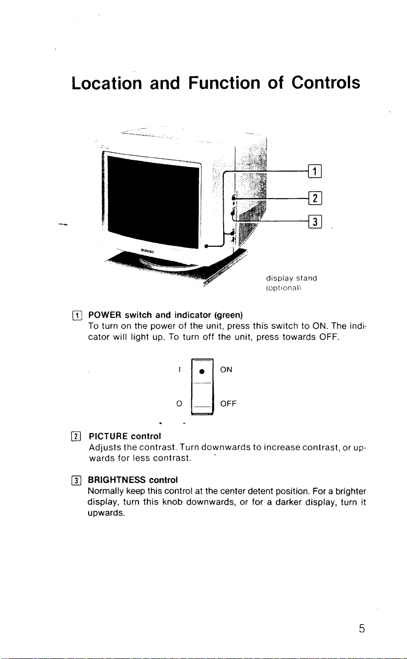
Location and Function
of
Controls
[II POWER switch and indicator (green)
To turn on the power
cator
will light up.
IT]
PICTURE control
Adjusts
wards
the
for
less
contrast.
of
To
turn
I
o
Turn
contrast.
the unit, press this
off
the unit, press towards OFF.
80N
ld
OFF
downwards
.
display
(optional)
to
increase
switch
stand
to ON. The
contrast,
[I] BRIGHTNESS control
Normally keep this control at the center detent position. For a brighter
display, turn this knob downwards,
upwards.
or
for a darker display, turn it
indio
or up·
5

Push upward
to
remove panel.
m H SHIFT (horizontal shift) control
Turn this control to center the displays of microcomputers, charac·
ter generators, etc. that are shifted toward the left or right side of
the screen.
m V SHIFT (vertical shift) control
Turn this control to eliminate any shifting in the vertical direction.
m H
SIZE
(horizontal size) control
Turn this control to adjust the horizontal
[]]
V SIZE (vertical size) control
Turn this control to adjust the vertical size.
size.
6
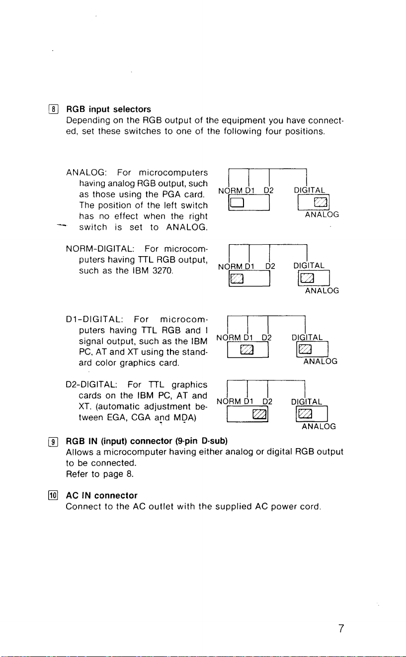
[!]
RGB input selectors
Depending on the RGB
ed, set these switches to one
output
of
the equipment you have connect-
of
the following four positions.
ANALOG: For
having analog
as those using the PGA card.
The position
has no effect when the right
switch
NORM-DIGITAL: For microcom-
puters having
such as the
microcomputers
RGB
of
the left switch
is
set
to
TIL
IBM
3270.
output, such
ANALOG.
RGB output,
I I I
NORM 01
10
I I
NORM
01
I~
D1-DIGITAL:
puters having
signal
PC,
AT and
ard color graphics card.
D2-DIGITAL: For
cards on the
XT.
(automatic adjustment
tween
111
RGB
IN
(input)
Allows a microcomputer having either analog or digital
be
connected.
to
Refer to page
For
microcom-
TIL
RGB and I
output, such as the IBM
XT
using the stand-
TIL
graphics
IBM
PC,
AT and
be-
EGA,
CGA
a[1d
MQA)
connector
8.
(9-pin D-sub)
I I I
NORM
01
I
~
I I I
NORM 01
1
02
I
I
02
I
02
I
02
~l
I
DIGITAL
101
ANALOG
I
DIGITAL
[g[J
ANALOG
I
DIGITAL
I~
ANALOG
I
DIGITAL
[g[J
ANALOG
RGB
output
1
[1QJ
AC
IN
connector
Connect to the AC
outlet
with
the
supplied
AC power cord.
7
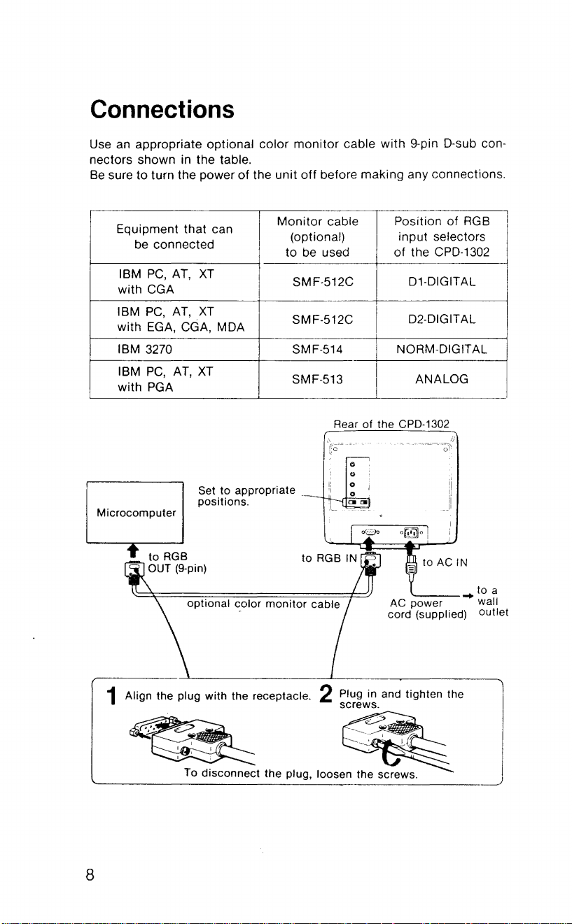
Connections
Use an appropriate optional color
monitor
cable
with
9-pin D-sub connectors shown in the table.
Be
sure to turn the power
Equipment that can
be
connected
PC,
IBM
AT,
with CGA
IBM
PC,
AT,
with EGA, CGA, MDA
XT
XT
of
the unit
off
before making any connections.
Monitor
cable Position of
(optional) input selectors
of
I
the CPD·1302
D1-DIGITAL
D2-DIGITAL
to
be
used
SMF·512C
SMF-512C
IBM 3270 SMF·514 NORM·DIGITAL
IBM
PC,
AT,
with
PGA
Microcomputer
XT
Set
to
appropriate .
positions.
SMF·513
Rear
'(;0=
..
.:
-~.
o
o
o
o
[]I'"
of
"
ANALOG
the CPD·1302
"
.'
",-,
-.
-""~--':-~---~
I;
RGB
!
I
'---
AC
optional
1 Align the plug with the receptacle. 2 Plug in and tighten the
-
~~
~
~
I
: To d:sconnect the plug, loosen the screws.
.
~olor
monitor
cable
screws.
----
..
__
~
power wall
cord (supplied) outlet
.
-~
' , I
8
___
to a
 Loading...