

Sony TRINITRON BVM-20M4DE, TRINITRON BVM-20M4E, TRINITRON BVM-14M4DE, TRINITRON BVM-14M4E Operation Manual

TRINITRON® COLOR VIDEO MONITOR
BVM-20M4DE
BVM-20M4E
BVM-14M4DE
BVM-14M4E
OPERATION MANUAL
1st Edition (Revised 1)
English/Italian

Owner’ s Recor d
The model and serial numbers are located at the rear.
Record these numbers in the spaces provided below.
Refer to these numbers whenever you call upon your
Sony dealer regarding this product.
Model No.
Serial No.
W ARNING
To prevent fire or shock hazard, do not
expose the unit to rain or moisture.
Dangerously high voltage are present
inside the unit.
Do not open the cabinet. Refer servicing
to qualified personnel only.
In the event of a malfunction or when maintenance is
necessary, consult an authorized Sony dealer.
V ORSICHT
WARNING
THIS APPARATUS MUST BE EARTHED
IMPORTANT
The wires in this mains lead are coloured in
accordance with the following code:
Green-and-yellow: Earth
Blue: Neutral
Brown: Live
As the colours of the wires in the mains lead of this
apparatus may not correspond with the coloured
markings identifying the terminals in your plug proceed
as follows:
The wire which is coloured green-and-yellow must be
connected to the terminal in the plug which is marked
by the letter E or by the safety earth symbol Y or
coloured green or green-and-yellow.
The wire which is coloured blue must be connected to
the terminal which is marked with the letter N or
coloured black.
The wire which is coloured brown must be connected
to the terminal which is marked with the letter L or
coloured red.
Ensure that your equipment is connected correctly - If
you are in any doubt consult a qualified electrician.
Um Feuergefahr und die Gefahr eines
elektrischen Schlages zu vermeiden, darf
das Gerät weder Regen noch Feuchtigkeit
ausgesetzt werden.
Im lnneren des Geräts liegt gefährliche
Hochspannung an. Öffnen Sie niemals das
Gehäuse, und überlassen Sie
Wartungsarbeiten stets nur qualifiziertem
Fachpersonal.
Sollten am Gerät Probleme auftreten oder
Wartungsarbeiten erforderlich werden, wenden Sie
sich an einen autorisierten Sony-Händler.

For the customers in Europe
This product with the CE marking complies with both
the EMC Directive (89/336/EEC) and the Low Voltage
Directive (73/23/EEC) issued by the Commission of
the European Community.
Compliance with these directives implies conformity to
the following European standards:
• EN60950: Product Safety
• EN55103-1: Electromagnetic Interference (Emission)
• EN55103-2: Electromagnetic Susceptibility
(Immunity)
This product is intended for use in the following
Electromagnetic Environment(s):
E1 (residential), E2 (commercial and light industrial),
E3 (urban outdoors) and E4 (controlled EMC
environment, ex. TV studio).
Pour les clients européens
Ce produit portant la marque CE est conforme à la fois
à la Directive sur la compatibilité électromagnétique
(EMC) (89/336/CEE) et à la Directive sur les basses
tensions (73/23/CEE) émises par la Commission de la
Communauté européenne.
La conformité à ces directives implique la conformité
aux normes européennes suivantes:
• EN60950: Sécurité des produits
• EN55103-1: Interférences électromagnétiques
(émission)
• EN55103-2: Sensibilité électromagnétique (immunité)
Ce produit est prévu pour être utilisé dans les
environnements électromagnétiques suivants:
E1 (résidentiel), E2 (commercial et industrie légère),
E3 (urbain extérieur) et E4 (environnement EMC
contrôlé ex. studio de télévision).
These products are designed for operation in the
environments E1 to E4. During EMC stress, the
performance (evaluated according to ITU/R 562-3 and
ITU/R 500-4) may degrade as shown in Table 1.
Without the EMC stress, all performance will recover to
full function.
Table 1
Frequency Level
14-inch Monitors 24-40 MHz 4-3
190-290, 360 and 4
420 MHz
20-inch Monitors 35-50 MHz 1
100 and 420 MHz 4
Ces produits sont conçus pour fonctionner dans les
environnements E1 à E4. Lors de contraintes EMC,
les performances (évaluées en fonction de ITU/R 5623 et ITU/R 500-4) risquent de chuter comme le montre
le tableau 1. Sans contrainte EMC, toutes les
performances reviennent à leur niveau maximum.
Tableau 1
Fréquence Niveau
Moniteurs 14 pouces 24-40 MHz 4-3
190-290, 360 et 4
420 MHz
Moniteurs 20 pouces 35-50 MHz 1
100 et 420 MHz 4
Für Kunden in Europa
Dieses Produkt besitzt die CE-Kennzeichnung und
erfüllt sowohl die EMV-Direktive (89/336/EEC) als
auch die Direktive Niederspannung (73/23/EEC) der
EG-Kommission.
Die Erfüllung dieser Direktiven bedeutet Konformität
für die folgenden Europäischen Normen:
• EN60950: Produktsicherheit
• EN55103-1: Elektromagnetische Interferenz
(Emission)
• EN55103-2: Elektromagnetische Empfindlichkeit
(Immunität)
Dieses Produkt ist für den Einsatz unter folgenden
elektromagnetischen Bedingungen ausgelegt:
E1 (Wohnbereich), E2 (kommerzieller und in
beschränktem Maße industrieller Bereich), E3
(Stadtbereich im Freien) und E4 (kontrollierter EMVBereich, z.B. Fernsehstudio)
Diese Produkte sind für den Einsatz in Umgebungen
vorgesehen, die den Normen E1 bis E4 entsprechen.
Bei EMV-Belastung kann die Leistung (bewertet nach
ITU/R 562-3 und ITU/R 500-4) wie in Tabelle 1
dargestellt abfallen. Bei Wegfall der EMV-Belastung
steigt die Leistung wieder auf den vollen Wert an.
Tabelle 1
Frequenz Stufe
14-Zoll-Monitore 24-40 MHz 4-3
190-290, 360 und 4
420 MHz
20-Zoll-Monitore 35-50 MHz 1
100 und 420 MHz 4


English
Precaution
Table of Contents
English
On safety
• Operate the unit only with a power source as
specified in “Specifications” section.
• The nameplate indicating operating voltage, power
consumption, etc., is located at the rear.
• Should any solid object or liquid fall into the cabinet,
unplug the unit and have it checked by qualified
personnel before operating it any further.
• Do not drop or place heavy objects on the power
cord. If the power cord is damaged, turn off the
power immediately. It is dangerous to use the unit
with a damaged power cord.
• Unplug the unit from the wall outlet if it is not to be
used for several days or more.
• Disconnect the power cord from the AC outlet by
grasping the plug, not by pulling the cord.
• The socket-outlet shall be installed near the
equipment and shall be easily accessible.
On installation
• Allow adequate air circulation to prevent internal
heat build-up.
Do not place the unit on surfaces (rugs, blankets,
etc.) or near materials (curtains, draperies) that may
block the ventilation holes.
• Do not install the unit in a location near heat sources
such as radiators or air ducts, or in a place subject to
direct sunlight, excessive dust, mechanical vibration
or shock.
Features ............................................................... 2(E)
Location and Function of Parts and Controls . 4(E)
Front ............................................................4(E)
Rear Panel ...................................................6(E)
Using On-Screen Menus..................................... 8(E)
On-Screen Menu Configuration ..................8(E)
Operation through On-Screen Menus .........9(E)
Functions of On-Screen Menus.................10(E)
Connections ....................................................... 12(E)
How to Connect the AC Power Cord ........12(E)
How to Connect a Cable to a
BNC Connector....................................12(E)
Specifications..................................................... 13(E)
About this manual
Before operating the unit, please read this manual
thoroughly and retain it for future reference.
The explanation given in this manual can be applied to
the following models unless noted otherwise.
When explanation differs among models, this is clearly
indicated in this manual.
• BVM-14M4DE/14M4E (14-inch monitor)
• BVM-20M4DE/20M4E (20-inch monitor)
Illustrations of the video monitor are of the BVM14M4DE.
On cleaning
To keep the unit looking brand-new, periodically clean
it with a mild detergent solution. Never use strong
solvents such as thinner or benzine, or abrasive
cleansers since they will damage the cabinet. As a
safety precaution, unplug the unit before cleaning it.
On repacking
Do not throw away the carton and packing materials.
They make an ideal container which to transport the
unit. When shipping the unit to another location,
repack it as illustrated on the carton.
If you have any questions about this unit, contact your
authorized Sony dealer.
1(E)

Features
Picture
HR (High Resolution) Trinitron 1) picture tube
HR Trinitron tube provides a high resolution picture.
Horizontal resolution is more than 800 TV lines at the
center of the picture.
Comb filter
When NTSC video signals are received, a comb filter
activates to make more accurate Y/C separation. This
contributes to less of a decrease in resolution, cross
color and cross luminance phenomena.
Beam current feedback circuit
The built-in beam current feedback circuit assures
stable white balance.
Four color system available
The monitor can display NTSC, PAL, SECAM and
NTSC
selected automatically.
Blue only mode
In the blue only mode, an apparent monochrome
display is obtained with all three cathodes driven with
a blue signal. This facilitates color saturation and
phase adjustments and observation of VCR noise.
2)
4.43
signals. The appropriate color system is
Input
COMPONENT SDI3) input/output connectors
for BVM-20M4DE/14M4DE
SMPTE 259M 4:2:2 serial digital signal from a digital
VCR can be input and output through these
connectors.
When you install a Sony Component SDI kit <Audio>
BKM-102 (not supplied), you can monitor the sound
from serial digital input signals with the picture.
Analog RGB/component input connectors
Analog RGB or component (Y, R-Y and B-Y) signals
from video equipment can be input through these
connectors.
Y/C input connectors
The video signal, split into the chrominance signal (C)
and the luminance signal (Y), can be input through this
connector, eliminating the interference between the
two signals, which tends to occur in a composite video
signal, ensuring video quality.
External sync input
When the EXT SYNC selector is in the on position,
the monitor can be operated on the sync signal
supplied from an external sync generator.
4)
Automatic termination
(connector with
mark only)
The input connector is terminated at 75 ohms inside
when no cable is connected to the loop-through output
connector. When a cable is connected to an output
connector, the 75-ohm termination is automatically
released.
.........................................................................................................................................................................................................
1) “Trinitron” is a registered trademark of Sony
Corporation.
2) The NTSC4.43 system refers to an NTSC color system in
which the subcarrier frequency is modified to 4.43MHz.
When an NTSC recorded video program is played back
with a Trident (PAL/SECAM/NTSC4.43) VTR, the
NTSC4.43 signal is output.
3) SDI: Serial Digital Interface
4) The Sony Component SDI Kit BKM-101C (for video) is
built in BVM-20M4DE/14M4DE.
2(E)
Functions
Underscan mode
The signal normally scanned outside of the screen can
be monitored in the underscan mode.
Note
When the monitor is in the underscan mode, the dark
RGB scanning lines may appear on the top edge of the
screen. These are caused by an internal test signal,
rather than the input signal.
Horizontal/vertical delay mode
The horizontal and vertical sync signals can be
checked simultaneously in the H/V delay mode.
Auto/manual degaussing
Degaussing of the screen can be performed
automatically when the power is turned on, or
manually by pressing the DEGAUSS button.
Five menu languages
You can select the menu language from among five
languages on the menu.
EIA 19-inch rack mount kit available
Use a suitable kit when rack mounting.
Europe MB-502C (14-inches) / SLR-103C (20-
inches
Any other area MB-502B (14-inches) /SLR-103A (20-
inches)
For details on mounting, refer to the instruction manuals
supplied with the mounting bracket kit or slide rail kit.
SDI (Serial Digital Interface) Kit (for audio) for
BVM-20M4DE/14M4DE
By using the Sony BKM-102 Component SDI Kit (for
audio, optional), you can monitor SMPTE 259M 4:2:2
serial digital audio signal from a digital VCR with the
picture.
On-screen menus
You can set color temperature, CHROMA SET UP,
and other settings by using the on-screen menus.
SDI (Serial Digital Interface) Kit for BVM20M4E/14M4E
By using the following optional SDI Kits, the monitor
can display SMPTE 259M 4:2:2 serial digital signal
from a digital VCR. (ex. Sony 4:2:2 VCR)
- BKM-101C: Component SDI Kit (for video)
- BKM-102: Component SDI Kit (for audio)
Note
When the serial number of the BKM-101C you want to
connect is less than 2,010,000, an optional connecting
harness (part no. 1-900-230-35) will be required.
Serial Remote Interface Kit
By using the Sony BKM-103 Serial Remote Interface
Kit (optional), the monitor can be controlled from
personal computers via the RS-422A serial interface.
3(E)

Location and Function of Parts and Controls
Front
1
!ª
LINE/
RGB
H/V
DELAY
!¢!∞!§
!•
EXT
SYNC
16:9
!£
MENU
EXIT
SELECT
ENTER
!¡!™
APERTURE
MIN
@º@¡@™
A/
RGB
COMPONENT
DEGAUSS UNDER
RESET
BLUE
ONLY
SDI
SCAN
C/
B/
!¶
1 Tally lamp
Lights up when the video camera connected to this
monitor is selected, indicating that the picture is being
recorded.
For details on how to light the tally lamp, see page 14(E).
2 POWER switch and indicator
Depress to turn on the monitor. The indicator will light
green.
CONTRAST
MAX
–+
MIN
PHASECHROMABRIGHT
MAX
PUR GRN MIN MAX MIN MAX
VOLUME
POWER
REMOTE
5 CONTRAST control
Turn this control clockwise to make the contrast higher
or counterclockwise to make it lower.
6 PHASE control
This control is effective only for the NTSC and
NTSC
4.43 color systems. Turn it clockwise to make the
skin tones greenish or counterclockwise to make them
purplish.
234 567890
3 REMOTE indicator
Lights up when you select ON on the USER PRESET
menu (see page 11(E)), or when you connect a
supplied cable to the REMOTE connector. The
controls on the front panel do not work when this
indicator lights up.
For details on how to connect the cable, see page 14(E).
4 VOLUME control
Turn this control clockwise or counterclockwise to
obtain the desired volume.
4(E)
7 CHROMA control
Turn this control clockwise to increase the color
intensity or counterclockwise to decrease it.
8 BRIGHT (brightness) control
Turn this control clockwise to increase the brightness
or counterclockwise to decrease it.
9 APERTURE control
Turn this control clockwise to increase sharpness or
counterclockwise to decrease sharpness.

Note
The PHASE (6), CHROMA (7) and APERTURE
(9) controls have no effect on the pictures of RGB
signals.
0 MENU/EXIT button
Press this button to display the main menu.
When a menu is on the display, you can return to the
previous menu by pressing this button.
!¡ ENTER/SELECT button
Press the button to confirm a selected item on the
menu.
!™ >/+ and ./– buttons
Press the buttons to move the cursor (z) or adjust
selected item on the menu.
!£ 16:9 selector
Press this selector (light on) to monitor the signals of
16:9 picture.
!¢ H (holizontal)/V (vertical) DELAY selector
Press this selector (light on) to observe the horizontal
and vertical sync signals at the same time.
The horizontal sync signal is displayed in the left
quarter of the screen; the vertical sync signal is
displayed near the center of the screen.
!∞ UNDER SCAN selector
Press this selector (light on) for underscanning.
The display size is reduced by approximately 5% so
that four corners of the raster are visible.
!§ BLUE ONLY selector and RESET button
• As the BLUE ONLY selector, press this selector
(light on) to eliminate the red and green signals.
Only blue signal is displayed as an apparent
monochrome picture on the screen. This facilitates
“chroma” and “phase” adjustments and observation
of VCR noise.
(“Phase” adjustment is effective only for the NTSC
signals.)
• As the RESET button, you can reset the menu
settings by pressing this button when a menu is on
the display.
!• EXT SYNC (external sync) selector
• Set this selector to the off position (light off) to
operate the monitor on the sync signal from the
displayed video signal.
• Set this selector to the on position (light on) to
operate the monitor on an external sync signal
through the EXT SYNC connector.
!ª LINE/RGB input selector
Press this selector to select the input to be monitored.
• Set this selector to the off position (light off) to
monitor the signal through the LINE A, LINE B or
LINE C connectors.
• Set this selector to the on position (light on) to
monitor the signal through the RGB/COMPONENT
connectors.
@º C/SDI selector
• When the LINE/RGB input selector is set to the
LINE position (light off), press this selector (light
on) to monitor the signal through the LINE C
connectors.
• When the LINE/RGB input selector is set to the
RGB position (light on), press this selector (light on)
to monitor the SDI signal.
@¡ B/COMPONENT selector
• When the LINE/RGB input selector is set to the
LINE position (light off), press this selector (light
on) to monitor the signal through the LINE B
connectors.
• When the LINE/RGB input selector is set to the
RGB position (light on), press this selector (light on)
to monitor the component signal through the RGB/
COMPONENT connectors.
@™ A/RGB selector
• When the LINE/RGB input selector is set to the
LINE position (light off), press this selector (light
on) to monitor the signal through the LINE A
connectors.
• When the LINE/RGB input selector is set to the
RGB position (light on), press this selector (light on)
to monitor the RGB signal through the RGB/
COMPONENT connectors.
!¶ DEGAUSS button
Press this button momentarily. The screen will be
demagnetized. Wait for 10 minutes or more before
using this button again.
5(E)
Location and Function of Parts and Controls
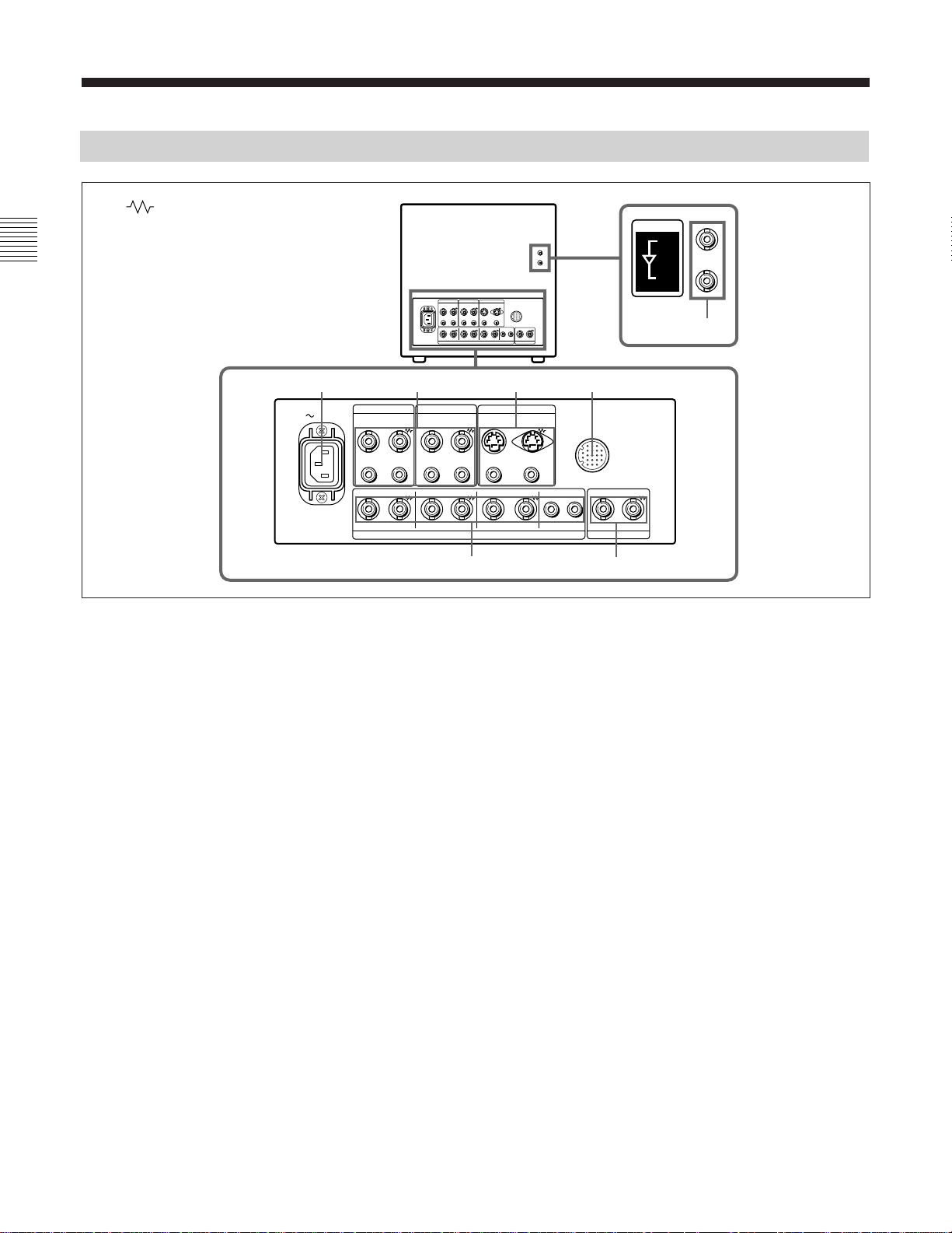
Rear Panel
(The mark indicates automatic termination.)
12 34
AC IN
LINE A LINE B
VIDEO VIDEO
IN OUTIN OUT
LINE C
IN OUT
REMOTE
COMPONENT SDI
IN
OUT
ACTIVE THROUGH
7
IN OUT IN OUT IN OUT
IN OUT IN OUT IN OUT IN OUT IN OUT
R/R–Y G/Y B/B–Y
AUDIOAUDIO AUDIO
RGB/COMPONENT EXT SYNC
1 AC IN socket
Connect the supplied AC power cord to this socket and
to a wall outlet.
2 LINE A, LINE B connectors
Two groups (A and B) of line input connectors for the
composite video and audio signals and their loopthrough output connectors.
To monitor the input signal through these connectors,
set the LINE/RGB selector to the LINE position (light
off) and press the A/RGB or B/COMPONENT selector
(light on).
VIDEO IN (BNC)
Connect to the video output of video equipment, such
as a VCR or a color video camera.
For a loop-through connection, connect to the video
output of another monitor.
VIDEO OUT (BNC)
Loop-through output of the VIDEO IN connector.
Connect to the video input of a VCR or another
monitor.
When the cable is connected to this connector, the
75-ohm termination of the input is automatically
released, and the signal input to the VIDEO IN
connector is output from this connector.
AUDIO
56
AUDIO IN (phono jack)
Connect to the audio output of a VCR or to a
microphone via a suitable microphone amplifier.
For a loop-through connection, connect to the audio
output of another monitor.
AUDIO OUT (phono jack)
Loop-through output of the AUDIO IN connector.
Connect to the audio input of a VCR or another
monitor.
3 LINE C connectors
Y/C IN (4-pin mini-DIN)
Connect to the Y/C separate output of a video camera,
VCR or other video equipment.
For a loop-through connection, connect to the Y/C
separate output of a VCR or another monitor.
Y/C OUT (4-pin mini-DIN)
Loop-through output of the Y/C IN connector.
Connect to the Y/C separate input of a VCR or another
monitor.
When the cable is connected to this connector, the 75ohm termination of the input is automatically released,
and the signal input to the Y/C IN connector is output
from this connector.
6(E)

AUDIO IN (phono jack)
Connect to the audio output of a VCR or a microphone
(via a suitable microphone amplifier).
To output the component signal
Connect to the R-Y/Y/B-Y component signal inputs of
a Betacam video recorder, etc.
AUDIO OUT (phono jack)
Loop-through output of the AUDIO IN connector.
Connect to the audio input of a VCR or another
monitor.
4 REMOTE connector (20-pin)
Connect to the tally output of a control console,
special-effect generator, etc. The tally lamp on the
front panel will be turned on and off by the connected
equipment. This connector can also be used for
connecting a remote control unit.
For details on the pin assignment of this connector, see
page 14(E).
5 RGB/COMPONENT connectors
RGB signal or component signal input connectors and
their loop-through output connectors.
To monitor the input signal through these connectors,
set the LINE/RGB selector to the RGB position (light
on), and press the A/RGB or B/COMPONENT
selector (light on).
R/R-Y IN, G/Y IN, B/B-Y IN (BNC)
When the EXT SYNC selector is set to the off position
(light off), the monitor operates on the sync signal
from the G/Y channel.
To monitor the RGB signal
Connect to the analog RGB signal outputs of a video
camera, etc.
AUDIO IN (phono jack)
Connect to the audio output of video equipment when
the analog RGB or component signal is input.
AUDIO OUT (phono jack)
Loop-through outputs of the AUDIO IN connector.
6 EXT SYNC (external sync) connectors
Press the EXT SYNC selector (light on) to use the
sync signal through this connector.
IN (BNC)
When this monitor operates on an external sync signal,
connect the reference signal from a sync generator to
this connector.
OUT (BNC)
Loop-through output of the IN connector. Connect to
the external sync input of video equipment to be
synchronized with this monitor.
When the cable is connected to this connector, the 75ohm termination of the input is automatically released,
and the signal input to the IN connector is output from
this connector.
BVM-20M4DE/14M4DE only
7 COMPONENT SDI IN/OUT connectors
To monitor the input signal through this connector, set
the LINE/RGB selector to the RGB position (light on),
and press the C/SDI selector (light on).
To monitor the component signal
Connect to the R-Y/Y/B-Y component signal outputs
of a Sony Betacam video camera, etc.
R/R-Y OUT, G/Y OUT, B/B-Y OUT (BNC)
Loop-through outputs of the R/R-Y IN, G/Y IN, B/BY IN connectors.
When the cables are connected to these connectors, the
75-ohm termination of the inputs is automatically
released, and the signal inputs to the R/R-Y IN, G/Y
IN, B/B-Y IN connectors are output from these
connectors.
To output the RGB signal
Connect to the analog RGB signal inputs of a video
IN (BNC)
Connect the SERIAL V/A OUT connectors of the
Digital BETACAM VTRs to allow input of SMPTE
259M/CCIR 656-III 4:2:2 serial digital signals.
OUT (BNC)
Outputs the digital signal of the equipment connected
to the COMPONENT SDI IN connector (Active loop-
1)
through
).
We recommend to connect the following cable to this
connectors.
Coaxial cable: 5C-2V (Max. 200 m, 656 feet)
Fujikura Europe Ltd (FEL) or the
equivalent
printer or another monitor.
..........................................................................................................................................................................................................
1) The signal from the IN connector is output through the OUT
connector when the power of the monitor is on.
7(E)
 Loading...