

Page 1
SONY@
VideoSig Menu
Problem Resolution Menu
3-800-731-12 (1)
Trinitron
®
Color Video Monitor
72
Trinitron
PVM-14N1A/14N1E/14N1U
PVM-14N2A/14N2E/14N2U
PVM-20N1 A/20N1 E/20N1 U
PVM-20N2A/20N2E/20N2U
©
1995 by Sony Corporation
Page 2
Owner’s Record
The model and serial numbers are located at the rear.
Record these numbers in the spaces provided below.
Refer to these numbers whenever you call upon your
Sony dealer regarding this product.
Model No.
Serial No.
To prevent fire or shock hazard, do not
expose the unit to rain or moisture.
Dangerously high voltage are present
inside the unit.
Do not open the cabinet. Refer servicing
to qualified personnel only.
In the event of a malfunction or when maintenance is
necessary, consult an authorized Sony dealer.
For the customers in the U.S.A.
This equipment has been tested and found to comply
with the limits for a Class A digital device, pursuant to
15
Part
provide reasonable protection against harmful
interference when the equipment is operated in a
commercial environment.
This equipment generates, uses, and can radiate radio
frequency energy and, if not installed and used in
accordance with the instruction manual, may cause
harmful interference to radio communications.
Operation of this equipment in a residential area is
likely to cause harmful interference in which case the
user will be required to correct the interference at his
own expense.
of the FCC Rules. These limits are designed to
For the customers in the United Kingdom
WARNING
THIS APPARATUS MUST BE EARTHED
IMPORTANT
The wires in this mains lead are coloured in
accordance with the following code:
Green-and-yellow: Earth
Blue:
Brown:
As the colours of the wires in the mains lead of this
apparatus may not correspond with the coloured
markings identifying the terminals in your plug proceed
as follows:
The wire which is coloured green-and-yellow must be
connected to the terminal in the plug which is marked
by the letter E or by the safety earth symbol
coloured green or green-and-yellow.
The wire which is coloured blue must be connected to
the terminal which is marked with the letter N or
coloured black.
The wire which is coloured brown must be connected
to the terminal which is marked with the letter L or
coloured red.
Ensure that your equipment is connected correctly - If
you are in any doubt consult a qualified electrician.
Neutral
Live
&
or
You are cautioned that any changes or modifications
not expressly approved in this manual could void your
authority to operate this equipment.
For the customers in Canada
This Class A digital apparatus meets all requirements
of the Canadian Interference-causing Equipment
Regulations.
2
Page 3
On safety
• Operate the unit only with a power source as
specified in “Specifications” section.
• The nameplate indicating operating voltage, power
consumption, etc., is located at the rear.
• Should any solid object or liquid fall into the cabinet,
unplug the unit and have it checked by qualified
personnel before operating it any further.
• Do not drop or place heavy objects on the power
cord. If the power cord is damaged, turn off the
power immediately. It is dangerous to use the unit
with a damaged power cord.
• Unplug the unit from the wall outlet if it is not to be
used for several days or more.
• Disconnect the power cord from the AC outlet by
grasping the plug, not by pulling the cord.
• The socket-outlet shall be installed near the
equipment and shall be easily accessible.
Features
Location and Function of Parts and Controls.......5
Using On-Screen Menus
Connections
Specifications...........................................................
Troubleshooting
.....................................................................
Front................................................................
RearPanel.........................................................6
...........................................
On-Screen MenuConfiguration
Operation through On-Screen Menus
Functionsof On-Screen Menus
.............................................................
How to Connect the AC Power Cord
How to Connect a Cable to a
BNC
Connector.........................................
......................................................
......................
..............
......................
............
10
13
.13
13
13
15
About this manual
Before operating the unit, please read this manual
thoroughly and retain it for future reference.
4
.5
8
.8
.9
On installation
Allow adequate air circulation to prevent internal
heat build-up.
Do not place the unit on surfaces (rugs, blankets,
etc.) or near materials (curtains, draperies) that may
block the ventilation holes.
Do not install the unit in a location near heat sources
such as radiators or air ducts, or in a place subject to
direct sunlight, excessive dust, mechanical vibration
or shock.
On cleaning
To keep the unit looking brand-new, periodically clean
it with a mild detergent solution. Never use strong
solvents such as thinner or
cleansers since they will damage the cabinet. As a
safety precaution, unplug the unit before cleaning it.
benzine,
or abrasive
On repacking
The explanation given in this manual can be applied to
the following models unless noted otherwise.
When explanation differs among models, this is clearly
indicated in this manual.
•
PVM-14N1A/l4N1E/14NlU (14-inch
•
PVM-l4N2A/l4N2E/l4N2U (14-inch
•
PVM-20NlA/20NlE/20NlU (20-inch
•
PVM-20N2A/20N2E/20N2U (20-inch
Illustrations of the video monitor are for the
20N2A/20N2E/20N2U.
monitor)
monitor)
monitor)
monitor)
PVM-
Do not throw away the carton and packing materials.
They make an ideal container which to transport the
unit. When shipping the unit to another location,
repack it as illustrated on the carton.
If you have any questions about this unit, contact your
authorized Sony dealer.
3
Page 4
=== Picture
Functions
Fine pitch
The fine pitch trinitron tube provides a high resolution
picture. Horizontal resolution is more than 500 TV
lines at the center of the picture.
Trinitron1) picture tube
Comb filter
When NTSC video signals are received, a comb filter
activates to make more accurate Y/C separation. This
contributes to less of a decrease in resolution, cross
color and cross luminance phenomena.
Beam current feedback circuit
The built-in beam current feedback circuit assures
stable white balance.
Four color system available
The monitor can display NTSC, PAL, SECAM and
NTSC4.432) signals. The appropriate color system is
selected automatically.
Input
On-screen menus
You can set monitor operation settings by using the
on-screen menus.
EIA
standard
By using an
monitor, not supplied) or
20-inch
mounted in an EIA standard
monitor, not supplied), the monitor can be
19-inch
MB-502B
rack mounting
mounting bracket (for a
SLR- 103A
19-inch
slide rail (for a
rack.
14-inch
Analog RGB input connectors
(for
PVM-l4N2A/l4N2E/l4N2U/2ON2A/2ON2E/
2ON2U
Analog RGB signals from video equipment can be
input through these connectors.
only)
Y/C input connectors
The video signal, split into the chrominance signal (C)
and the luminance signal
connector. eliminating the interference between the
two signals. which tends to occur in a composite video
signal, ensuring video quality.
(Y),
can be input through this
Automatic termination
(connector with + mark only)
The input connector is terminated at 75 ohms inside
when no cable is connected to the loop-through output
connector. When a cable is connected to an output
connector. the
released.
75-ohm
termination is automatically
. ..............................................................................................................................................................................................................
1)
“Trinitron”
2)
The
an NTSC recorded video program is played back with a Trident
output.
is a registered trademark of Sony Corporation.
NTSC
4.43
system refers to an NTSC color system in which the subcarrier frequency is modified to
(PAL/SECAM/NTSC4.43)
4.43MHz.
VTR, the NTSC4.43 signal is
When
4
Page 5
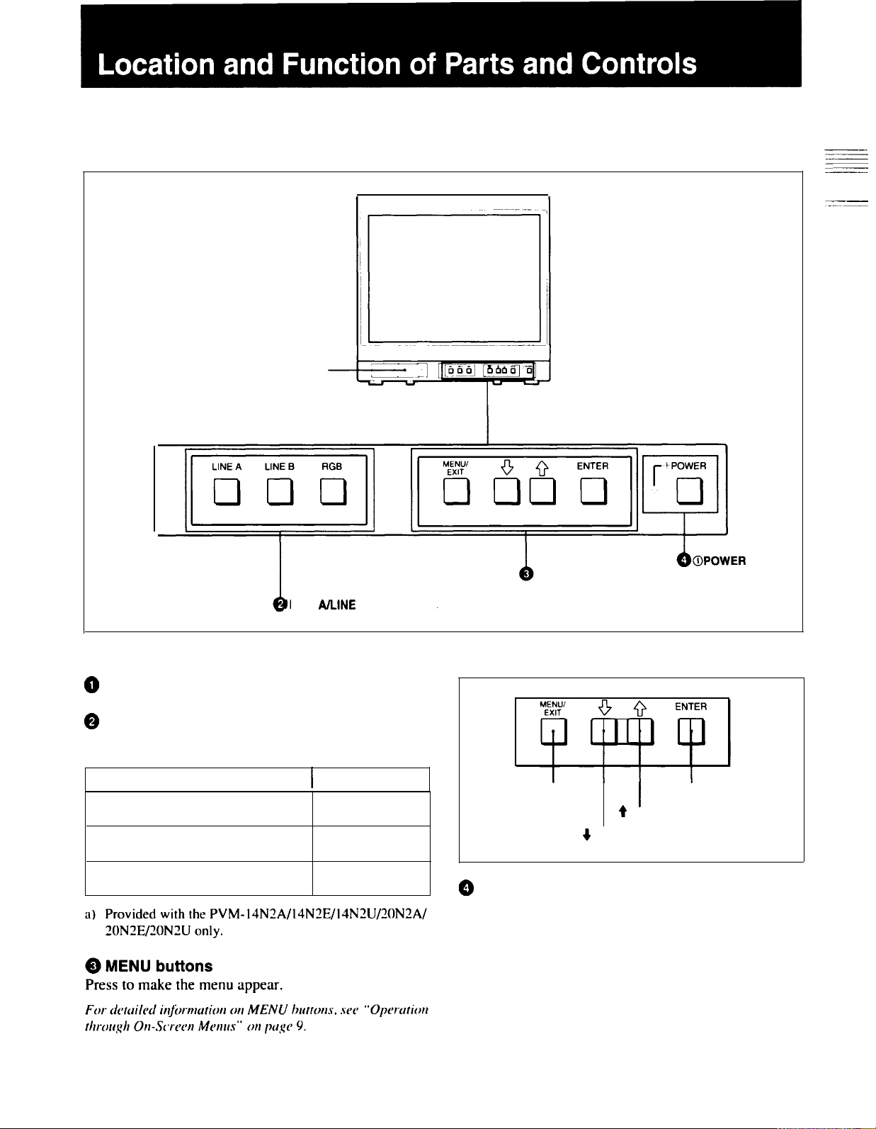
Front
@Speaker
LINE B/RGB buttons
PVM-20N2A/20N2E/20N2U front panel
0
Speaker
@
LINE A/LINE B/RGB (input select) buttons
Press to select the program to be monitored.
Input signal
Signal fed through the LINE A
connector
Signal fed through the LINE B
connector
Signal fed through the
connectors
a)
RGB
Press
LINE A
LINE B
a)
RGB
MENU buttons
MENU/EXIT button
+ button
0
(1)POWER switch and indicator
e
button
I
switch and
indicator
ENTER button
Press to turn the monitor on. The indicator lights in
green.
To turn the power off, press this again.
Page 6

Location and Function of Parts and Controls
Rear Panel
LINE A connectors
LINE B connectors
RGB
connectors
-AClN
4REMOTE
PVM-2ON2A/2ON2E/2ON2U
@
LINE A connectors
Input connectors for the composite video, Y/C separate
video and audio signals and their loop-through output
connectors.
To monitor the input signal fed through these
connectors, press the LINE A button on the front
panel.
The Y/C IN connector has priority over the VIDEO IN
connector.
When connecting the cable to the Y/C IN connector,
the Y/C IN connector is automatically selected and the
VIDEO IN connector is disconnected even if the cable
is connected.
Y/C IN connector
(4-pin
mini-DIN)
Connect to the Y/C separate output connector of a
video camera, VCR or other video equipment.
connector
@-AC
IN connector
(The w mark indicates automatic termination.)
rear panel
When the cable is connected to this connector, the
75ohm termination of the input is automatically released,
and the signal input to the Y/C IN connector is output
from this connector.
VIDEO IN connector
(BNC-type)
Connect to the video output connector of video
equipment, such as a VCR or a color video camera.
For a loop-through connection, connect to the video
output connector of another monitor.
VIDEO OUT connector
(BNC-type)
Loop-through output connector of the VIDEO IN
connector. Connect to the video input connector for a
VCR or another monitor.
When the cable is connected to this connector, the
75
ohm termination of the input is automatically released,
and the signal input to the VIDEO IN connector is
output from this connector.
Y/C OUT connector
(4-pin
mini-DIN)
Loop-through output of the Y/C IN connector.
Connect to the Y/C separate input connector of a VCR
or another monitor.
6
AUDIO IN connector (phono jack)
Connect to the audio output connector of a VCR or
other equipment. For a loop-through connection,
connect to the audio output of another monitor.
Page 7

AUDIO OUT connector (phono jack)
Loop-through output of the AUDIO IN connector.
Connect to the audio input connector of a VCR or
another monitor.
@
LINE B connectors
Input connectors for the composite video, Y/C separate
video and audio signals.
To monitor the input signal fed through these
connectors, press the LINE B button on the front
panel.
EXT SYNC (external sync input) connector
(BNC-type)
Connect to the sync signal output of a video camera,
VCR or other video equipment.
When you set RGB SYNC to SYNC ON GREEN in
the menu, the monitor operates on the sync signal from
the G channel so that it is not necessary to use this
connector.
For detailed information on sync signal setting, see
RGB SYNC menu “on page 12 of “Functions of On-Screen
Menus”.
“m
==
==
Y/C IN connector
Connect to the Y/C separate output connector of a
video camera, VCR or other video equipment.
VIDEO IN connector (BNC-type)
Connect to the video output connector of video
equipment, such as a VCR or a color video camera.
For a loop-through connection, connect to the video
output connector of another monitor.
AUDIO IN connector (phono jack)
Connect to the audio output connector of a VCR or
other equipment. For a loop-through connection,
connect to the audio output of another monitor.
0
RGB connectors
(provided with the
14N2U /20N2A/20N2E/20N2U
Analog RGB input connectors for the R/G/B signals,
external sync signals and audio signals.
To monitor the input signal fed through these
connectors, press the RGB button on the front panel.
(4-pin
mini-DIN)
PVM-l4N2A/l4N2E/
only)
a
REMOTE connector (phono jack)
(provided with the
14N2U /20N2A/20N2E/20N2U
This connector functions as follows.
Open: When this connector is open, the current input
signal is selected.
Ground: By grounding this connector, the input
signal selected before this current signal is selected.
@
*AC
IN (inlet) connector
Connect the supplied AC power cord to this connector
and to a wall outlet.
PVM-l4N2A/l4N2E/
only)
R/G/B (input) connectors
Connect to the analog RGB outputs connectors of a
video camera, VCR or other video equipment. The
monitor operates on the external sync signal.
The monitor also can operate on the sync signal from
the G channel by setting RGB SYNC to SYNC ON
GREEN in the menu.
For detailed information on sync signal setting, see [3a]
RGB SYNC menu “on page 12 of “Functions of On-Screen
Menus”.
AUDIO IN connector (phono jack)
Connect to the audio output connectors of video
equipment when the analog RGB signal is input.
(BNC-type)
7
Page 8

You can make various settings and adjustments of the
monitor using the on-screen menus.
On-Screen Menu Configuration
The on-screen menu is composed of the following two
menu types.
Item selection menu
You can select an adjustment and setting item such as
sound volume, contrast, brightness, color intensity,
color system and menu language by using the
e,+
and
ENTER buttons.
On-screen menu tree-chart
Item selection menus
Regular screen
El
[1] MENU 1
Adjustment and setting menus
You can make desired adjustment or setting on
corresponding menu. The settings and adjustments
remain unchanged until next adjustment even if you
turn off the power.
To reset the settings and adjustments to the
settings, select “ FACTORY PRESET” from
MEMORY menu.
Adjustment and setting menus
m VOLUME
m
CONTRAST menu
~BRIGHTNESS
m CHROMA
m
PHASE menu
menu
menu
menu
factory-
HUSER
a) These menus
8
[2] MENU 2
[3] MENU
([3]
[3a] and d are provided with
BCOLOR
p&J DISPLAY
~LANGUAGE
B
3a)
m
l
m
SELECT menu
menu
menu
USER MEMORY menu
RGB SYNC
ASPECT RATIO
menu
a)
menu
PVM-l4N2A/l4N2E/l4N2U /20N2A/20N2E/20N2U
a)
only.
Page 9

Operation through On-Screen Menus
Menu operation buttons
There are four menu operation buttons on the front
panel of the monitor.
Usable buttons depend on the displayed menu. Buttons
that can be used on the menu are displayed at the
bottom line of the screen. You can perform menu
operation using displayed buttons.
Menu
BRIGHTNESS
STD
@ MENU/EXIT
bbtton
+
button
e
button
6
ENTER button
Button functions depend on the displayed menu. The
following table shows the button functions on the item
selection menus and adjustment and setting menus.
Button
Q*
@
ENTER
a)
You
can
use the
MEMORY menu of the adjustment and setting menus.
Function on the Function on the
item selection
menus
To move the
cursor upward.
To decide a
selected item.
ENTER
button only on
adjustment and
setting menus
To increase
value/select item.
To decide a
selected
themUSER
item
a
98
.
Usable buttons
Display of the usable menu operation buttons
Usable buttons
Operating pro&lures
To display the menu, follow this procedure.
1
Press the MENU/EXIT
(a)
button.
l MENU 1 appears.
To select items other than ones not displayed
on MENU 1
Select l MENU 2 or l MENU 3
For details of how to select, see the
item selection menus” described later.
2
Move the cursor to the desired item by pressing
the
q
or t
Press the ENTER
3
(@, e)
button.
(0)
button.
The adjustment and setting menu selected in step
2 appears.
l)
.
“To
change the
1) l MENU 3 is provided with
For detailed information of menus, see “Functions of
Screen
~~~~~~~~~~~~~~~~~~~~~~~~~~~~~~~~~~~~~~~
Menus”
on page
only.
On-
IO.
Page 10

Using On-Screen Menus
To change the item selection menus
Select NEXT PAGE on
selection menu and PREVIOUS PAGE on
display
the
previous
MENU 1
a-b :
When selecting NEXT PAGE
+-
:
When selecting PREVIOUS PAGE
a)
MENU 3 is provided with
20N2E/20N2U only.
How to change the item selection menu
the
menu to display next
item
selection menu.
MENU 2
PVM-14N2A/14N2E/14N2U/20N2A/
MENU
the
3
item
menu
a)
to
To return to the item selection menu from the
adjustment and setting menus
Press the thetMENU/EXIT
displayed adjustment and setting menu.
(a)
botton on the currently
To close the menu (to return to the regular
screen)
Press the MENU/EXIT
selection menu is displayed. The on-screen menu
disappears and the regular screen appears.
(a)
button when the
item
Functions of On-Screen Menus
Item selection menus
[1] MENU 1
MENU 1 menu has
1
VOLUME
1
CONTRAST
BRIGHTNESS1 To adjust the brightness
I
1
PHASE
I
[2] MENU 2
MENU 2 menu has the following selection items.
1
Item
COLOR
SELECT
1
DISPLAY
LANGUAGE
I
USER MEMORY
[3] MENU 3
(for
PVM-142A/14N2E/14N2U/20N2A/
20N2E/20N2U only)
MENU 3 menu has the following selection items.
the
following selection items.
To obtain the desired volume
I
1
To adjust the contrast
-1
1
To adjust the color intensity
1
To adjust the phase
Function
I
To select the color system of the
input signal
1
To select period of display
1
To select the menu language
To store and recall the values and
settings adjusted by a user, and
recall the factory-settings
I
I
I
I
10
Item
I
RGB SYNC
ASPECT RATIO To select the aspect ratio
Function
I
To select the sync signal when the
RGB signals are input
Adjustment and setting menu
[1a] VOLUME menu (Factory setting: 50)
5o
ZZ”S7
1
Adjust the speaker volume.
The volume increases by pressing the e
The volume decreases by pressing 4
tIIzJ
button.
button.
I
Page 11

1
blICONTRAST menu (Factory setting: 60)
CONTRAST
60
-ADJUST
m
Adjust the contrast of the screen.
The contrast becomes higher by pressing the e button.
The contrast becomes lower by pressing + button.
lc BRIGHTNESS menu (Factory setting: STD)
BRIGHTNESS
: :STD
Adjust the brightness of the screen.
The screen becomes brighter by pressing the
The screen becomes darker by pressing + button.
M
CHROMA menu (Factory setting: STD)
t
button.
The phase of an NTSC composite video signal or a
Y/C separate signal can be corrected on this menu. The
PAL composite video signal or a Y/C separate signal
and RGB signals cannot be corrected.
2a COLOR SELECT menu
(Factory setting: AUTO)
Select the color system of the input signal.
AUTO: Input color systems are
automatically, selected.
When you input NTSC signal, trap filter will
activate. To monitor NTSC signal with comb filter,
select NTSC COMB in this menu.
2b DISPLAY menu
(Factory setting: SHORT TIME)
DISPLAY
b.sHORT
TIME
LONG TIME
OFF
Adjust the color intensity of the video signal.
The color intensity strengthens by pressing the
t
button.
The color intensity weakens by pressing + button.
The color intensity of an composite video signal or a
Y/C separate signal can be corrected on this menu.
That of the RGB signals cannot be corrected.
le PHASE menu (Factory setting: STD)
Adjust the phase of the video signals.
The skin tone becomes greenish by pressing the
button.
The skin tone becomes purplish by pressing the
button.
t
+
-SELECT
cm3
Select the period of displaying the color system of the
current input signals.
The items have the following functions.
Function
SHORT TIME
1
OFF
2c
LANGUAGE menu
To display the kind of color system
being used for several seconds on
the screen each time you change the
signal input.
To display the kind of color system
being used for approximately five
minutes on the screen each time you
change the signal input.
Not to display the kind of the color
system.
(Factory setting: ENGLISH)
LANGUAGE
l ENGLISH
DEUTSCH
FRANGAlS
ITALIAN0
ESPAflOL
Select the menu language among the five languages,
English, German, French, Italian and Spanish.
11
Page 12

Using On-Screen Menus
2d
USER MEMORY menu
I
USER
MEMORY
RECALL
FACTORY PRESET
The items have the following functions.
1
Item
STORE
FACTORY
PRESET
a)
The current settings and adjusted values are reset to the
Function
To store all adjustments and
settings currently set on each menu
into the internal memory.
To recall all adjustments and
settings currently stored in the
internal memory.
To reset the adjustments and
settings currently set on each menu
to the factory
settings.
a)
factory settings. The values and settings adjusted and
stored in the internal memory by using the STORE
menu, however, are not changed. To reset internally
stored adjusted values and settings to the factory setting,
select FACTORY PRESET, first, then select STORE.
When you press the ENTER
(0)
button, the following
message is displayed for about two seconds. The
currently selected item becomes active when pressing
the ENTER
(0)
button.
The following menus are provided with the
PVM-
14N2A/l4N2E/l4N2U /PVM-20N2A/20N2E/20N2U
only.
3a RGB SYNC menu
I
(Factory setting: EXT SYNC)
RGB
SYNC
EXT SYNC
SYNC ON GREEN
~SELECT
Select the sync signal when the RGB signals are input.
The items have the following functions.
Item
EXT SYNC
SYNC ON
GREEN
3b ASPECT RATIO menu
III
(Factory setting:
ASPECT RATIO
'43
16 9
IBBSELECT
mm
Function
To operate the monitor on an external
sync signal fed through the RGB SYNC
connector.
To operate the monitor on the sync
signal from the G channel.
4:3)
cmcl
FACTORY PRESET
12
Select the aspect ratio of the screen.
Page 13

How to Connect the AC Power Cord
Video signal
Color system
Connect the AC power cord (supplied) to the
connector and to a wall outlet.
~AC
IN
Resolution
Frequency response
Picture performance
Normal scan 7 % over scan of CRT effective
H. linearity
V. linearity
Color temperature 6,500 K
Inputs
LINE A/B
How to Connect a Cable to a BNC Connector
Connect the coaxial cable with the BNC connectors to
the BNC connectors on the rear panel as illustrated
below.
Insert the connector into the BNC
connector on the rear panel,
matching the slit and pin, and turn
the cable BNC connector clockwise
to secure the BNC connector of a
coaxial cable.
RGB
20N2U
REMOTE
20N2E/20N2U
NTSC, PAL, SECAM,
NTSC4.43
500 TV lines
LINE
RGB
6 MHz±3dB (Y signal)
6 MHz±3dB
screen area
Y/C IN
Less than 8.0
Less than 7.0
4-pin mini-DIN(X2)
%
(typical)
%
(typical)
See the pin assignment on the next
page.
VIDEO IN
AUDIO IN
BNC connector
-6
dB,
sync negative
Phono jack
(X2),
(X2), 1Vp-p +3 dB,
-5
dBua),
more
than 47 kilo-ohms
(PVM-l4N2A/l4N2E/l4N2U/20N2A/20N2E/
only)
R/G/B
BNC connector
0.7 Vp-p +3
dB,
(X3)
-6
dB
Sync on green: 0.3 Vp-p, negative,
Automatic 75 ohms termination
AUDIO IN
Phono jack (xl), -5
dBua),
more
than 47 kilo-ohms
EXT SYNC BNC connector
4 Vp-p +3
dB,
-6
(Xl)
dB,
sync negative
(PVM-l4N2A/l4N2E/l4N2U/20N2A/
only)
Phono jack
(Xl)
Open: currently selected input
signal
Low state (GND): input signal
selected prior to the current
input signal
a) 0
dBu =
0.775
Vr.m.s.
13
Page 14

Specifications
Outputs
LINE A
Y/C OUT
4-pin
mini-DIN
Automatic 75 ohms termination
VIDEO OUT
BNC connector
Automatic 75 ohms termination
AUDIO OUT
Phono jack
Speaker output Output level: 0.8 W
General
CRT
Power consumption
Power requirements
Operating temperature
Storage temperature
Relative humidity 0 to 90
Dimensions (w/h/d)
PVM-14NlA/l4NlE/l4NlU/
14N2A/l4N2E/l4N2U:
14-inch CRT with P-22
phosphor
Visible picture size 340 mm
(13-inch
PVM-20NlA/20NlE/20NlU/
20N2A/20N2E/20N2U:
20-inch
phosphor
Visible picture size 490 mm 1
( 19-inch
PVM-14NlA/l4NlE/l4NlU: 80W
PVM-l4N2A/l4N2E/l4N2U: 80W
PVM-20NlU/20N2U: 1OOW
PVM-20Nl
20N2E:
100 to 240 V AC,
“For use of
20Nl
U/20N2 U”,
monitors on 120 V AC.
0 to +35˚C (32 to
-10 to
+40°C
%
PVM-14N1A/l4N1E/l4NlU/
14N2A/l4N2E/l4N2U:
346X34Ox414 mm
(135/8 x 131/2
PVM-20NlA/20NlE/20NlU/
20N2A/20N2E/20N2U:
449X44lx502mm
(173/4
x l73/8 X
(xl)
loop-through,
(xl)
loop-through,
(xl)
loop-through
measured diagonally)
CRT with P-22
measured diagonally)
A/20N2A/20NlE/
105 W
50/60Hz
PVM-14N/
U/14N2U//
operate these
95˚F)
(14
to 1O4˚F)
x
163/8
inches)
197/8 inches)
Mass
PVM-14NlA/l4NlE/l4NlU/
14N2A/l4N2E/l4N2U:
Approx. 15 kg (33 lb 1 oz)
PVM-20NlA/20NlE/20NlU/
20N2A/20N2E/20N2U:
Approx. 28 kg (61 lb 12 oz)
Accesory
supplied
AC power cord (1)
Operating Instructions (1)
Pin assignment
Y/C IN connector (4-pin mini-DIN)
Pin No.
2
3
4
Design and specifications are subject to change
without notice.
Signal
Y-input
CHROMA
subcarrier-input
GND for Y-input
GND for
CHROMA-input
Description
1 Vp-p, sync negative,
75 ohms
0.286 Vp-p (NTSC),
300m Vp-p (PAL),
burst
Delay time between Y
and C: within 0 ± 100
nsec., 75 ohms
GND
GND
14
Page 15

This section may help you isolate the problem. Should
the problem persist, unplug the unit and contact your
Sony dealer or local authorized Sony service facility.
Symptom
If noise is generated on the screen when the color system
of the input signal is changed in AUTO mode selected on
the COLOR SELECT menu
If noise is generated on the screen when the NTSC
COMB mode is selected on the COLOR SELECT menu
If the horizontal lines will intermittently appear on the
upper screen, when
ASPECT RATIO menu
If colors are not accurately reproduced
16:9
aspect ratio is selected on the
,
Possible
It takes approximately two seconds to automatically detect the
color system. After detecting the color system, the picture will
be stable.
When an unstable input signal may generate noise seen on the
screen. Select the NTSC mode on the COLOR SELECT menu.
This is for beam current feedback. These horizontal liens
disappear when the white balance is stabilized.
The monitor input signal is deviated from the color system
specifications (i.e. signals from VCRs).
Proceed as follows to correct this phenomenon.
1 Confirm the color system of the input signal.
2
Select the same color system as that of the input signal on
the COLOR SELECT menu.
If the problem remains unsolved after corresponding color
system is selected, briefly turn OFF the power, then turn ON
the monitor again.
causes and remedies
15
 Loading...