

Sony trimaster EL PVM-2551MD Instructions For Use Manual

Professional
4-409-417-13(2)
Video Monitor
Instructions for Use
Before operating the unit, please read this manual thoroughly
and retain it for future reference.
PVM-2551MD
© 2011 Sony Corporation

Owner’s Record
The model and serial numbers are located at the rear.
Record these numbers in the spaces provided below.
Refer to these numbers whenever you call upon your
Sony dealer regarding this product.
Model No. ____________________
Serial No. ____________________
WARNING
To reduce the risk of fire or electric shock, do
not expose this apparatus to rain or moisture.
To avoid electrical shock, do not open the
cabinet. Refer servicing to qualified personnel
only.
WARNING
THIS APPARATUS MUST BE EARTHED.
To disconnect the main power, unplug the AC plug.
WARNING
When installing the unit, incorporate a readily
accessible disconnect device in the fixed wiring, or
connect the power plug to an easily accessible socketoutlet near the unit. If a fault should occur during
operation of the unit, operate the disconnect device to
switch the power supply off, or disconnect the power
plug.
WARNING
Make sure the surface is wide enough so that this
apparatus’s width and depth don’t exceed the surface’s
edges.
If not, this apparatus may lean or fall over and cause an
injury.
CAUTION
The apparatus shall not be exposed to dripping or
splashing. No objects filled with liquids, such as vases,
shall be placed on the apparatus.
Do not install the appliance in a confined space, such as
book case or built-in cabinet.
Consult with Sony qualified personnel for mounting
arm, wall or ceiling mount installation.
Caution
When you dispose of the unit or accessories, you must
obey the laws in the relative area or country and the
regulations in the relative hospital.
CAUTION
The unit is not disconnected from the AC power source
(mains) as long as it is connected to the wall outlet, even
if the unit itself has been turned off.
For the customers in the U.S.A.
This equipment has been tested and found to comply
with the limits for a Class A digital device, pursuant to
Part 15 of the FCC Rules. These limits are designed to
provide reasonable protection against harmful
interference when the equipment is operated in a
commercial environment. This equipment generates,
uses, and can radiate radio frequency energy and, if not
installed and used in accordance with the instruction
manual, may cause harmful interference to radio
communications. Operation of this equipment in a
residential area is likely to cause harmful interference in
which case the user will be required to correct the
interference at his own expense.
You are cautioned that any changes or modifications not
expressly approved in this manual could void your
authority to operate this equipment.
All interface cables used to connect peripherals must be
shielded in order to comply with the limits for a digital
device pursuant to Subpart B of Part 15 of FCC Rules.
This device complies with Part 15 of the FCC Rules.
Operation is subject to the following two conditions: (1)
this device may not cause harmful interference, and (2)
this device must accept any interference received,
including interference that may cause undesired operation.
For the customers in Canada
This Class A digital apparatus complies with Canadian
ICES-003.
This unit has been certified according to Standard CAN/
CSA-C22.2 No. 60601-1.
For the customers in the U.S.A and Canada
When you use this product connected to 240 V single
phase, be sure to connect this product to a center tapped
circuit.
WARNING:
Using this unit at a voltage other than 120 V may require
the use of a different line cord or attachment plug, or
both. To reduce the risk of fire or electric shock, refer
servicing to qualified service personnel.
For the customers in Europe
The manufacturer of this product is Sony Corporation,
1-7-1 Konan, Minato-ku, Tokyo, 108-0075 Japan.
The Authorized Representative for EMC and product
safety is Sony Deutschland GmbH, Hedelfinger Strasse
61, 70327 Stuttgart, Germany. For any service or
2
guarantee matters please refer to the addresses given in
separate service or guarantee documents.
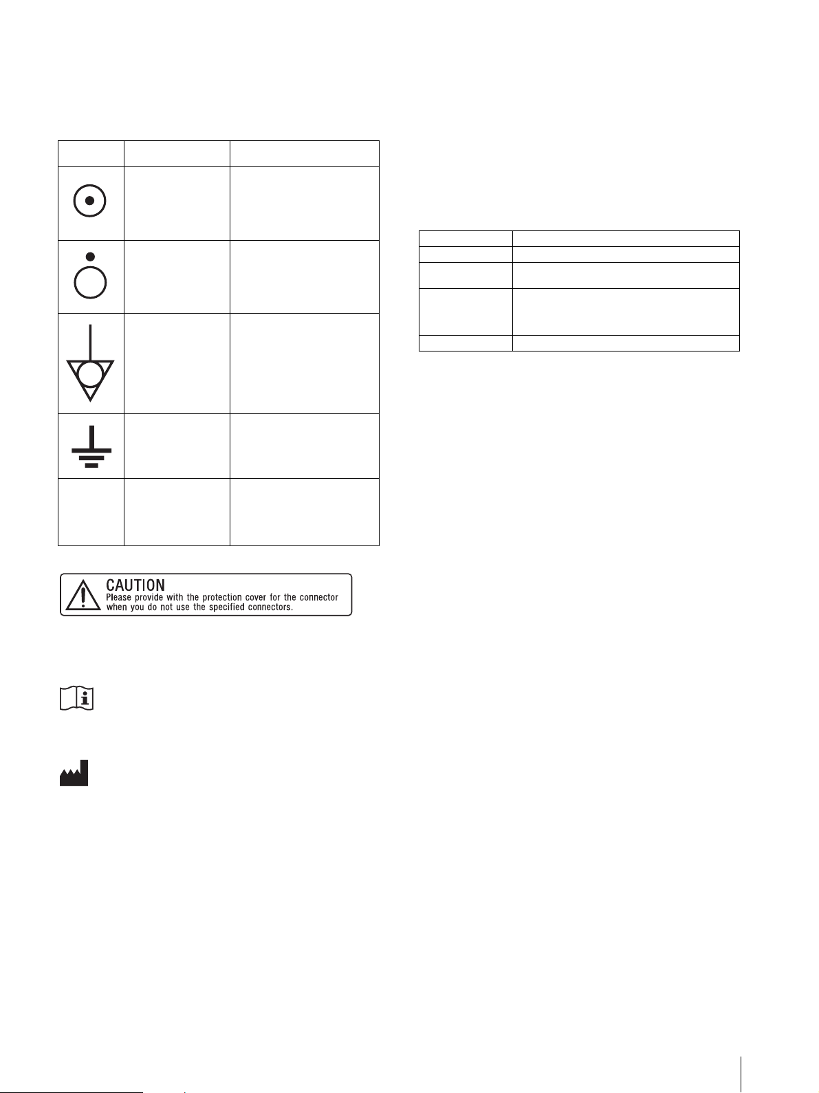
Symbols on the unit
Symbol Location This symbol indicates
Bottom Power switch.
Press to turn the monitor
on.
If you have questions on the use of the above Power
Cord / Appliance Connector / Plug, please consult a
qualified service personnel.
WARNING on power connection for medical
use
Please use the following power supply cord. With
connectors (plug or female) and cord types other than
those indicated in this table, use the power supply cord
that is approved for use in your area.
Bottom Power switch.
Rear The equipotential
Rear Functional earth terminal
Front Key inhibit
-
Press to turn the monitor
off.
terminal which brings the
various parts of a system
to the same potential.
The setting are locked so
that they cannot be
changed.
This CAUTION is located on the rear of the unit.
See page 19 of these instructions for details about how
to attach the connector cover.
Refer to the operating instructions
Follow the directions in the operating
instructions for parts of the unit on which this
mark appears.
This symbol indicates the manufacturer, and
appears next to the manufacturer’s name and
address.
WARNING on power connection
Use a proper power cord for your local power supply.
1. Use the approved Power Cord (3-core mains lead) /
Appliance Connector / Plug with earthing-contacts
that conforms to the safety regulations of each
country if applicable.
2. Use the Power Cord (3-core mains lead) / Appliance
Connector / Plug conforming to the proper ratings
(Voltage, Ampere).
United States and Canada
Plug Type HOSPITAL GRADE*
Co rd Ty p e Mi n . Typ e S J T
Minimum Rating
for Plug and
Appliance
Couplers
Safety Approval UL Listed and CSA
*Note: Grounding reliability can only be achieved when the
equipment is connected to an equivalent receptacle marked ‘Hospital
Only’ or ‘Hospital Grade’.
Min. 18 AWG
10A/125V
Important safeguards/notices for use in the
medical environments
1. All the equipments connected to this unit shall be
certified according to Standard IEC60601-1,
IEC60950-1, IEC60065 or other IEC/ISO Standards
applicable to the equipments.
2. Furthermore all configurations shall comply with the
system standard IEC60601-1-1.
Everybody who connects additional equipment to
the signal input part or signal output part configures
a medical system, and is therefore, responsible that
the system complies with the requirements of the
system standard IEC60601-1-1.
If in doubt, consult the qualified service personnel.
3. The leakage current could increase when connected
to other equipment.
4. For this particular equipment, all accessory
equipment connected as noted above, must be
connected to mains via an additional isolation
transformer conforming with the construction
requirements of IEC60601-1 and providing at least
Basic Insulation.
5. This equipment generates, uses, and can radiate radio
frequency energy. If it is not installed and used in
accordance with the instruction manual, it may cause
interference to other equipment. If this unit causes
interference (which can be determined by
unplugging the power cord from the unit), try these
measures: Relocate the unit with respect to the
susceptible equipment. Plug this unit and the
susceptible equipment into different branch circuit.
3
Consult your dealer. (According to standard EN606011-2 and CISPR11, Class B, Group 1)
6. Model PVM-2551MD is a monitor intended for use
in a medical environment to display pictures from
cameras or other systems, other than diagnostic Xray equipment.
Important EMC notices for use in the medical environments
• The PVM-2551MD needs special precautions
regarding EMC and needs to be installed and put into
service according to the EMC information provided in
this instructions for use.
• The portable and mobile RF communications
equipment such as cellular phones can affect the
PVM-2551MD.
Warning
The use of accessories and cables other than those
specified, with the exception of replacement parts sold
by Sony Corporation, may result in increased emissions
or decreased immunity of the PVM-2551MD.
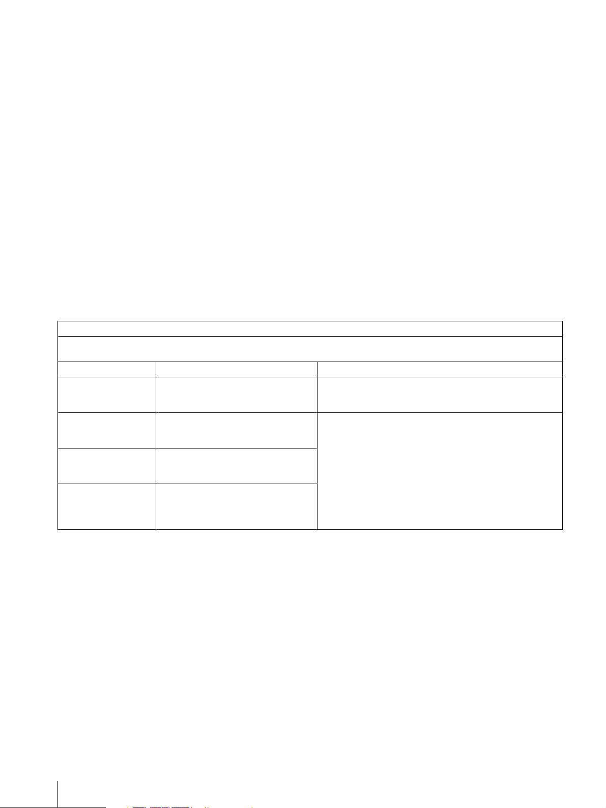
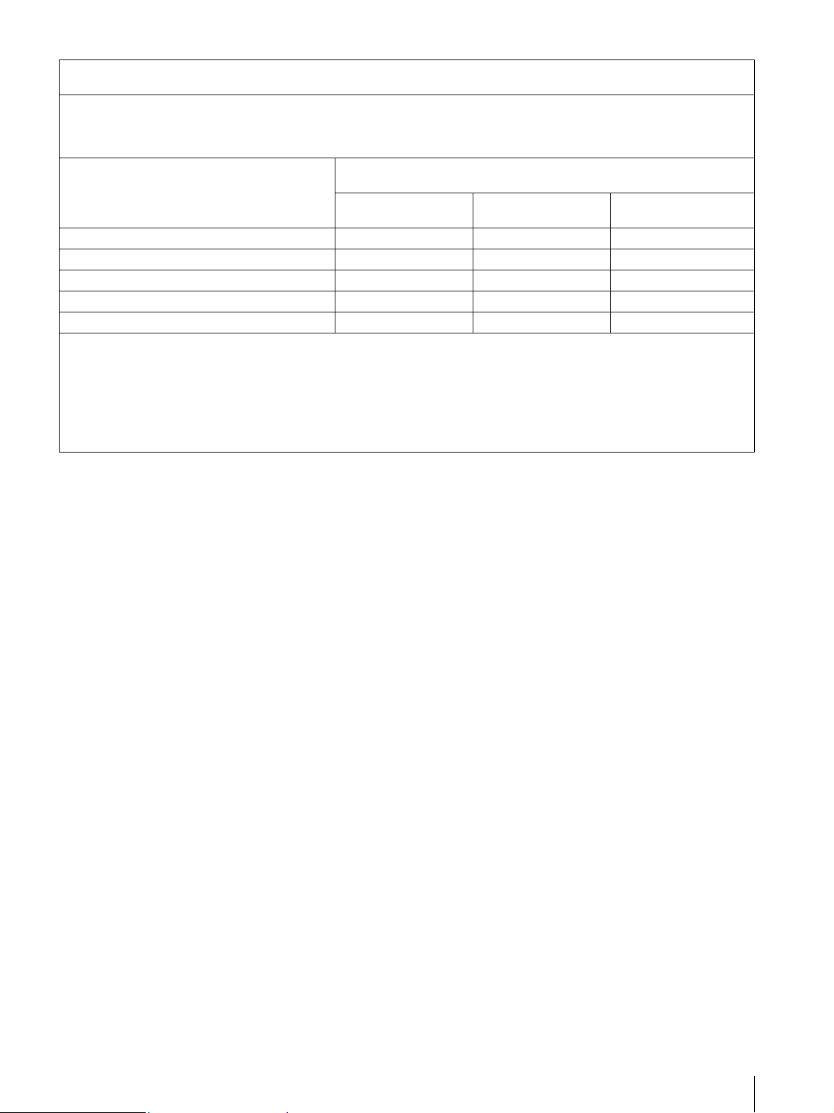
Guidance and manufacturer’s declaration-electromagnetic emissions
The PVM-2551MD is intended for use in the electromagnetic environment specified below.
The customer or the user of the PVM-2551MD should assure that it is used in such an environment.
Emission test Compliance Electromagnetic environment-guidance
RF emissions
CISPR 11
RF emissions
CISPR 11
Harmonic emissions
IEC 61000-3-2
Voltage fluctuations/
flicker emissions
IEC 61000-3-3
Group 1
Class B
Class D
Complies
The PVM-2551MD uses RF energy only for its internal
function. Therefore, its RF emissions are very low and are not
likely to cause any interference in nearby electronic equipment.
The PVM-2551MD is suitable for use in all establishments,
including domestic establishments and those directly connected
to the public low-voltage power supply network that supplies
buildings used for domestic purposes.
Warning
If the PVM-2551MD should be used adjacent to or
stacked with other equipment, it should be observed to
verify normal operation in the configuration in which
it will be used.
4
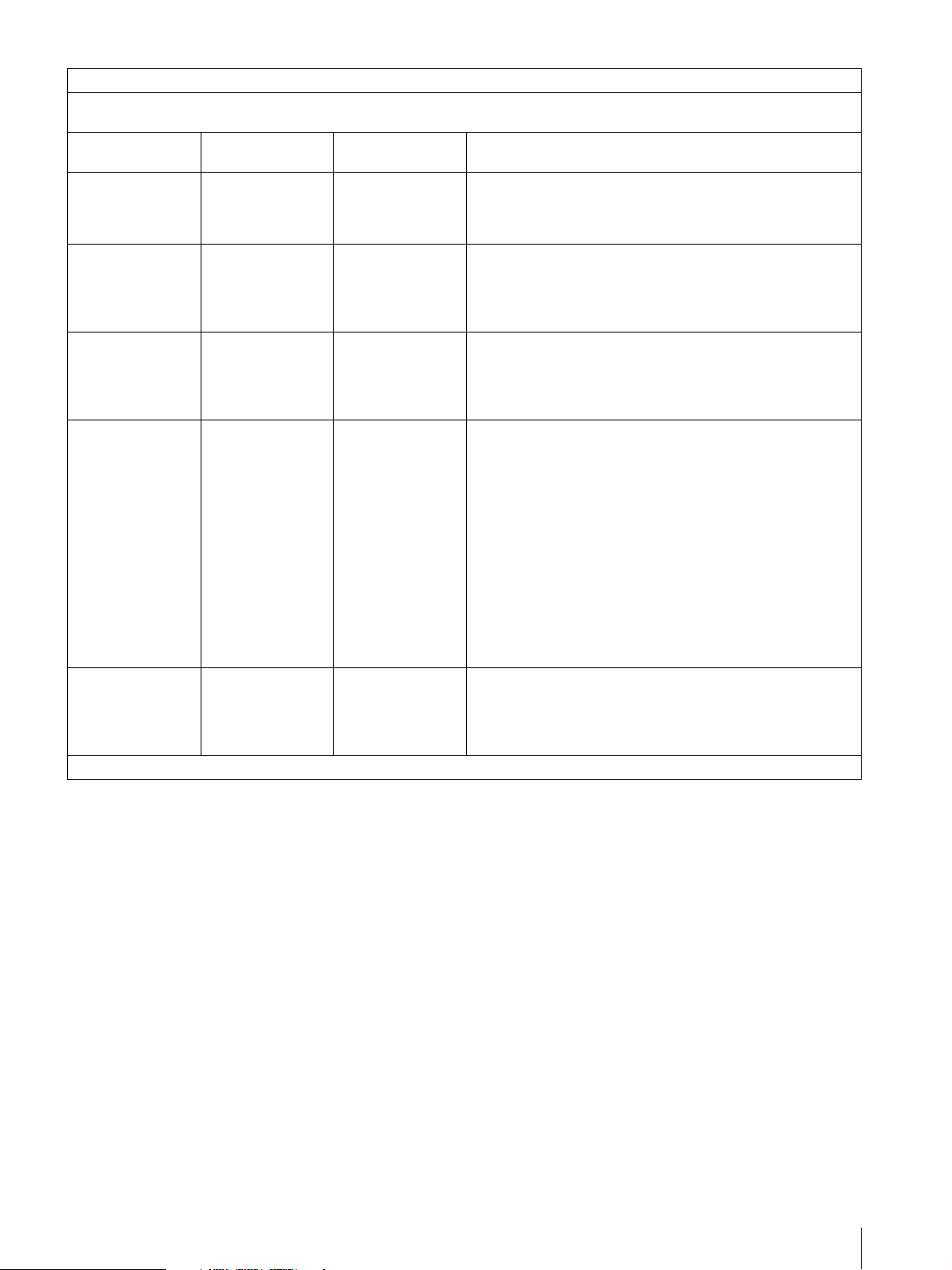
Guidance and manufacturer’s declaration - electromagnetic immunity
The PVM-2551MD is intended for use in the electromagnetic environment specified below. The customer or the user of the PVM2551MD should assure that it is used in such as environment.
Immunity test
Electrostatic
discharge (ESD)
IEC 60601 test
level
±6 kV contact
±8 kV air
Compliance level Electromagnetic environment - guidance
±6 kV contact
Floors should be wood, concrete or ceramic tile. If floors are
covered with synthetic material, the relative humidity should be
±8 kV air
at least 30%.
IEC 61000-4-2
Electrical fast
transient/burst
±2 kV for power
supply lines
±2 kV for power
supply lines
Mains power quality should be that of a typical commercial or
hospital environment.
IEC 61000-4-4
Surge
IEC 61000-4-5
Voltage dips, short
interruptions and
voltage variations
on power supply
input lines
IEC 61000-4-11
Power frequency
(50/60Hz)
magnetic field
IEC 61000-4-8
NOTE: U
is the a.c. mains voltage prior to application of the test level.
T
±1 kV for input/
output lines
±1 kV differential
mode
±2 kV common
mode
< 5% U
(> 95% dip in U
T
for 0.5 cycle
±1 kV for input/
output lines
±1 kV differential
mode
±2 kV common
mode
< 5% UT
)
(> 95% dip in U
T
for 0.5 cycle
Mains power quality should be that of a typical commercial or
hospital environment.
Mains power quality should be that of a typical commercial or
)
hospital environment. If the user of the PVM-2551MD requires
T
continued operation during power mains interruptions, it is
recommended that the PVM-2551MD be powered from an
40% U
T
(60% dip in UT)
for 5 cycles
70% U
T
(30% dip in U
for 25 cycles
< 5% U
(> 95% dip in U
T
T
for 5 sec
)
)
T
40% U
T
(60% dip in UT)
for 5 cycles
70% U
T
(30% dip in U
for 25 cycles
< 5% U
(> 95% dip in U
T
T
for 5 sec
uninterruptible power supply or a battery.
)
)
T
3 A/m 3 A/m Power frequency magnetic fields should be at least characteristic
of a typical location in a typical commercial or hospital
environment.
5
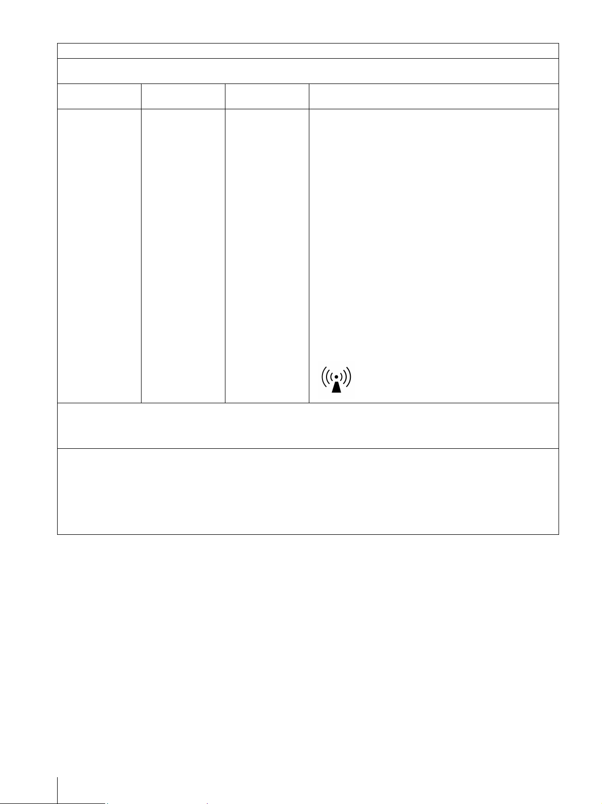
Guidance and manufacturer’s declaration - electromagnetic immunity
The PVM-2551MD is intended for use in the electromagnetic environment specified below. The customer or the user of the PVM2551MD should assure that it is used in such as environment.
Immunity test
IEC 60601 test
level
Compliance level Electromagnetic environment - guidance
Portable and mobile RF communications equipment should be
used no closer to any part of the PVM-2551MD, including
cables, than the recommended separation distance calculated
from the equation appliance to the frequency of the transmitter.
Recommended separation distance
Conducted RF
IEC 61000-4-6
Radiated RF
IEC 61000-4-3
NOTE 1: At 80 MHz and 800 MHz, the higher frequency range applies.
NOTE 2: These guidelines may not apply in all situations. Electromagnetic propagation is affected by absorption and reflection from
structures, objects and people.
a Field strengths from fixed transmitters, such as base stations for radio (cellular/cordless) telephones and land mobile radios, amateur
radio, AM and FM radio broadcast and TV broadcast cannot be predicted theoretically with accuracy. To assess the electromagnetic
environment due to fixed RF transmitters, an electromagnetic site survey should be considered. If the measured field strength in the
location in which the PVM-2551MD is used exceeds the applicable RF compliance level above, the PVM-2551MD should be
observed to verify normal operation. If abnormal performance is observed, additional measures may be necessary, such as
reorienting or relocating the PVM-2551MD.
3 Vrms
150 kHz to 80 MHz
3 V/m
80 MHz to 2.5 GHz
3 Vrms
3 V/m
d = 1.2 √P
d = 1.2 √P 80 MHz to 800 MHz
d = 2.3 √P 800 MHz to 2.5 GHz
Where P is the maximum output power rating of the transmitter
in watts (W) according to the transmitter manufacturer and d is
the recommended separation distance in meters (m).
Field strengths from fixed RF transmitters, as determined by an
electromagnetic site survey,
level in each frequency range.
Interference may occur in the vicinity of equipment marked with
following symbol:
a
should be less than the compliance
b
b Over the frequency range 150 kHz to 80 MHz, field strengths should be less than 3 V/m.
6
Recommended separation distances between portable and mobile RF communications equipment and the PVM2551MD
The PVM-2551MD is intended for use in an electromagnetic environment in which radiated RF disturbances are controlled. The
customer or the user of the PVM-2551MD can help prevent electromagnetic interference by maintaining a minimum distance between
portable and mobile RF communications equipment (Transmitters) and the PVM-2551MD as recommended below, according to the
maximum output power of the communications equipment.
Rated maximum output power of transmitter
W
150 kHz to 80 MHz
0.01 0.12 0.12 0.23
0.1 0.38 0.38 0.73
1 1.2 1.2 2.3
10 3.8 3.8 7.3
100 12 12 23
For transmitters rated a maximum output power not listed above, the recommended separation distance d in meters (m) can be
estimated using the equation applicable to the frequency of the transmitter, where P is the maximum output power rating of the
transmitter in watts (W) according to the transmitter manufacturer.
NOTE 1: At 80 MHz and 800 MHz, the separation distance for the higher frequency range applies.
Separation distance according to frequency of transmitter
80 MHz to 800 MHz
d = 1.2 √P
m
800 MHz to 2.5 GHz
d = 1.2 √P
d = 2.3 √P
NOTE 2: These guidelines may not apply in all situations. Electromagnetic propagation is affected by absorption and reflection from
structures, objects and people.
7

Table of Contents
Precaution .............................................................. 9
On Safety ............................................................ 9
On Installation .................................................... 9
Handling the Screen ........................................... 9
On Burn-in ......................................................... 9
On a Long Period of Use .................................... 9
On Cleaning ..................................................... 10
Disposal of the Unit ......................................... 10
Recommendation to Use more than One
Unit ................................................................. 10
On Repacking ................................................... 10
On Fan Error .................................................... 10
On Moisture Condensation .............................. 10
Features ................................................................ 11
Location and Function of Parts and
Controls ................................................................ 13
Front Panel ....................................................... 13
Input Signals and Adjustable/Setting Items ..... 15
Rear Panel ........................................................ 16
Connecting the AC Power Cord ......................... 18
Installing the Input Adaptor .............................. 19
Removing the Connector Cover ......................... 19
Selecting the Default Settings ............................. 20
Selecting the Menu Language ............................ 21
Using the Menu .................................................... 22
Loading USER MEMORY ................................. 24
Adjustment Using the Menus ............................. 24
Items ................................................................. 24
Adjusting and Changing the Settings ............... 25
STATUS menu............................................. 25
COLOR TEMP/SPACE menu..................... 26
USER CONTROL menu.............................. 26
USER CONFIG menu.................................. 28
REMOTE menu ........................................... 33
KEY INHIBIT menu.................................... 34
USER MEMORY menu .............................. 35
Saving the user memory............................... 35
Troubleshooting ................................................... 36
Specifications ....................................................... 37
Dimensions ........................................................... 45
8
Table of Contents

Precaution
• The screen and the cabinet become warm during
operation. This is not a malfunction.
On Safety
• Operate the unit only with a power source as specified
in the “Specifications” section.
• A nameplate indicating operating voltage, power
consumption, etc., is located on the rear panel.
• Should any solid object or liquid fall into the cabinet,
unplug the unit and have it checked by qualified
personnel before operating it any further.
• Do not drop or place heavy objects on the power cord.
If the power cord is damaged, turn off the power
immediately. It is dangerous to use the unit with a
damaged power cord.
• Unplug the unit from the wall outlet if it is not to be
used for several days or more.
• Disconnect the power cord from the AC outlet by
grasping the plug, not by pulling the cord.
• The socket-outlet shall be installed near the equipment
and shall be easily accessible.
On Installation
• Allow adequate air circulation to prevent internal heat
build-up.
Do not place the unit on surfaces (rugs, blankets, etc.)
or near materials (curtains, draperies) that may block
the ventilation holes.
• Do not install the unit in a location near heat sources
such as radiators or air ducts, or in a place subject to
direct sunlight, excessive dust, mechanical vibration
or shock.
On Burn-in
Due to the characteristics of the material used in the
OLED panel for its high-precision images, permanent
burn-in may occur if still images are displayed in the
same position on the screen continuously, or repeatedly
over extended periods.
Images that may cause burn-in
• Masked images with aspect ratios other than 16:9
• Color bars or images that remain static for a long time
• Character or message displays that indicate settings or
the operating state
To reduce the risk of burn-in
• Turn off the character displays
Press the MENU button to turn off the character
displays. To turn off the character displays of the
connected equipment, operate the connected
equipment accordingly. For details, refer to the
operation manual of the connected equipment.
• Turn off the power when not in use
Turn off the power if the monitor is not to be used for
a prolonged period of time.
Screen saver
This product has a built-in screen saver function to
reduce burn-in. When an almost still image is displayed
for more than 10 minutes, the screen saver starts
automatically and the brightness of the screen decreases.
On a Long Period of Use
Handling the Screen
• The panel fitted to this unit is manufactured with high
precision technology, giving a functioning pixel ratio
of at least 99.99%. Thus a very small proportion of
pixels may be “stuck”, either always off (black),
always on (red, green, or blue), or flashing. In
addition, over a long period of use, because of the
physical characteristics of the panel, such “stuck”
pixels may appear spontaneously. These problems are
not a malfunction.
• Do not leave the screen facing the sun as it can damage
the screen. Take care when you place the unit by a
window.
• Do not push or scratch the monitor’s screen. Do not
place a heavy object on the monitor’s screen. This may
cause the screen to lose uniformity.
Due to an OLED’s panel structure and characteristics of
materials in its design, displaying static images for
extended periods, or using the unit repeatedly in a high
temperature/high humidity environments may cause
image smearing, burn-in, areas of which brightness is
permanently changed, lines, or a decrease in overall
brightness.
In particular, continued display of an image smaller than
the monitor screen, such as in a different aspect ratio,
may shorten the life of the unit.
Avoid displaying a still image for an extended period, or
using the unit repeatedly in a high temperature/high
humidity environment such an airtight room, or around
the outlet of an air conditioner.
To prevent any of the above issues, we recommend
reducing brightness slightly, and to turn off the power
whenever the unit is not in use.
Precaution
9

On Cleaning
On Repacking
Before cleaning
Be sure to disconnect the AC power cord from the AC
outlet.
On cleaning the monitor
A material that withstands disinfection is used for the
front protection plate of the medical use monitor. The
protection plate surface is especially treated to reduce
reflection of light. When solvents such as benzene or
thinner, or acid, alkaline or abrasive detergent, or
chemical cleaning cloth are used for the protection plate
surface/monitor surface, the performance of the monitor
may be impaired or the finish of the surface may be
damaged. Take care with respect to the following:
• Clean the protection plate surface/monitor surface
with a 50 to 70 v/v% concentration of isopropyl
alcohol or a 76.9 to 81.4 v/v% concentration of
ethanol using a swab method. Wipe the protection
plate surface gently (wipe using less than 1 N force).
• Stubborn stains may be removed with a soft cloth such
as a cleaning cloth lightly dampened with mild
detergent solution using a swab method and then clean
using the above chemical solution.
Never use solvents such as benzene or thinner, or acid,
alkaline or abrasive detergent, or chemical cleaning
cloth for cleaning or disinfection, as they will damage
the protection plate surface/monitor surface.
• Do not use unnecessary force to rub the protection
plate surface/monitor surface with a stained cloth.
The protection plate surface/monitor surface may be
scratched.
• Do not keep the protection plate surface/monitor
surface in contact with a rubber or vinyl resin product
for a long period of time. The finish of the surface
may deteriorate or the coating may come off.
Do not throw away the carton and packing materials.
They make an ideal container which to transport the
unit.
If you have any questions about this unit, contact your
authorized Sony dealer.
On Fan Error
The fan for cooling the unit is built in. When the fan
stops and the RETURN button on the front panel blinks
for fan error indication, turn off the power and contact an
authorized Sony dealer.
On Moisture Condensation
If the unit is brought directly from a cold place to a warm
place, or the unit is warm and the ambient temperature
cools suddenly (by air-conditioning, for example),
moisture may condense on the surface or inside of the
unit, or create a mist residue inside the protection plate.
This is called moisture condensation, and is not a
malfunction of the product itself, although it may cause
damage to the unit.
Leave the unit in a condensation free area.
If moisture condensation has occurred, turn off the unit
and do not use it until moisture condensation has
evaporated.
Disposal of the Unit
Do not dispose of the unit with general waste.
Do not include the monitor with household waste.
When you dispose of the monitor, you must obey the law
in the relative area or country.
Recommendation to Use more than One Unit
As problems can occasionally occur for the monitor,
when the monitor is used for safety control of personnel,
assets or stable picture, or for emergencies, we strongly
recommend you use more than one unit or prepare a
spare unit.
10
Precaution

Features
optimum light wave lengths and diminish undesired
light wave lengths.
The panel’s 10-bit driver enables smooth gradation of
color shading.
The PVM-2551MD (25-type) Professional Video
Monitor is a high performance color video monitor. This
is suitable for use in fields where precise image
reproduction is required.
It features OLED panel and “TRIMASTER
*1
,” which is
a new technology developed for three elements,
“accurate color reproduction,” “precision imaging” and
“quality picture consistency,” that are in demand for
professional use. “TRIMASTER” decreases the viewing
difference that occurs due to the individuality of each
panel. Also, it realizes high picture quality and hightrust by the color management system with its wide
color gamut device, high-resolution/precise gradation
display, highly accurate signal processing and panel
correction function.
*1
TRIMASTER is a trademark of Sony Corporation.
Advantages of OLED panel technology
The OLED panel makes use of an organic material,
which emits light when an electric current is applied.
Being self-emitting, the strength of luminescence can be
controlled by the amount of electric current. This brings
about the following three features:
*2
“Super Top Emission” is a trademark that represents the
OLED technology of Sony Corporation.
Compliance with medical safety
standards in U.S.A., Canada and Europe
IEC 60601-1 and product safety standards in the U.S.A.,
Canada and Europe have been obtained for this monitor.
The monitor is designed for use in the medical treatment
field, with the sheet switch, screen protect panel, etc.
Picture
Fully digital 10-bit signal processing circuit
As well as digital signals, all signals including analog
signals are converted into digital signals. All signals are
processed using a fully digital 10-bit processing circuit
so that an image is produced in smooth gradation
without any deterioration of quality.
Two color system available
The monitor can display NTSC and PAL signals by
connecting this unit.
Quick motion picture response:
The luminescent state of the OLED panel can be
changed instantaneously by changing the current flow in
the organic material. This enables a quick motion
picture response and production of images with minimal
blurring and ghosting.
High contrast and wide dynamic range:
The OLED panel does not emit light when black signal
is applied to the monitor, enabling a pure black screen to
be displayed. Furthermore, thanks to a wide dynamic
range the panel impressively displays brilliance and
clarity of various sparkling images, such as stars in a
night sky twinkling, night illuminations winking or glass
glittering, etc.
Rich color reproduction:
An OLED panel’s self-luminescence also allows for
great color reproduction across the entire spectrum in
practically any shade or brightness.
Sony’s Super Top Emission
*2
OLED panel
The 25-type full HD (1920 × 1080) OLED panel
features Sony’s Super Top Emission structure. Unlike
the conventional bottom emission structure of TFT,
Sony’s OLED panel can reproduce a crisper image due
to high brightness. Furthermore, a unique microcavity
structure makes RGB primary colors purer and deeper
by utilizing light resonance effects that magnify
Auto chroma/phase function
The chroma and phase of the decoder are automatically
adjusted with the auto chroma phase function.
Input
Accepts analog RGB input signals
Adopting the scan converter allows this monitor to
detect VGA, SVGA, XGA and SXGA analog RGB
signals input to the HD15 input connector.
Accepts DVI-D (digital) input signals
Adopting the scan converter allows this monitor to
detect VGA, SVGA, XGA and SXGA digital computer
signals input to the DVI input connector.
The number of the DVI input connectors can be
increased by installing the optional input adaptor into
the optional input port.
To view more than SXGA signals when the DVI input is
selected, use the cable within 3 m (118
length.
*3
For acceptable formats, see “About the preset signal” on
page 40.
Optional port
Two optional input adaptors can be installed. The
composite, Y/C, component, analog RGB, SDI or DVID signal can be input depending on the input connectors
of the board to be used. SDI supports not only HD-SDI
*3
*3
1
/8 inches) in
Features
11

and SD-SDI, but also 3G-SDI, which transmits twice as
much data as HD-SDI with a Single-link.
Multi-format
*4
NTSC or PAL color system or DTV format, such as
720p, 1080i, etc. can be selected automatically.
*4
For acceptable formats, see “Available signal formats” on
page 39.
External sync input
The unit can be operated on the sync signal supplied
from an external sync generator.
Functions
APA (Auto Pixel Alignment) function
You can display pictures from the HD15 input connector
in the appropriate picture by simply pressing the
function button that APA is assigned.
Automatic termination (connector with
mark only)
The input connector is terminated internally at 75 ohms
when nothing has been connected to the output
connector. If a cable is connected to the output
connector, the internal terminal is automatically
released and the signals input to the input connector are
output to the output connector (loop-through).
Screen saver
To reduce burn-in, the brightness of the screen can be
automatically decreased when a still image is displayed
for more than 10 minutes.
Key inhibit function
You can inhibit the key to prevent missing an operation.
User memory function
You can save the 20 picture settings with the name. The
user memory data can be saved or loaded between the
monitor and the equipment (PC, etc.) connected in
serial remote mode.
Two kinds of ground terminals
Two kinds of ground terminals are built into the monitor
to equal the electric potential.
External remote function
The input signal is selected or various items are adjusted
by use of the serial (Ethernet) remote function. You can
connect this unit to the monitor by the Ethernet
(10BASE-T/100BASE-TX) connection and controlled
remotely on the network.
For more information, see SERIAL REMOTE of
REMOTE menu on page 34.
Other
Select color temperature and gamma mode
You can select the color temperature from among three
(D93, D65, D56) settings and gamma mode from among
six settings (1.8, 2.0, 2.2, 2.4, 2.6, DICOM). You can
also adjust the color temperature to the appropriate
setting in “USER1,” “USER2” or “USER3.”
Two-dis play
Two kinds of input signals are put on the monitor.
For more information, see “MULTI DISPLAY
SETTING” on page 30.
Color space feature
You can select ITU-R BT.709, EBU or SMPTE-C for the
color space settings.
Aspect setting
You can set the monitor to 4:3 or 16:9 display mode
according to the input signal.
Scan function
You can select the display from among “NORMAL,”
“OVER,” “FULL” and “NATIVE” except the HD15 and
DVI input signals.
Optional stand
It is more convenient to install the monitor on a desk by
using the optional stand (SU-560).
Select language display
You can select your language for the display from seven
languages - English, French, German, Spanish, Italian,
Japanese and Chinese.
12
Features
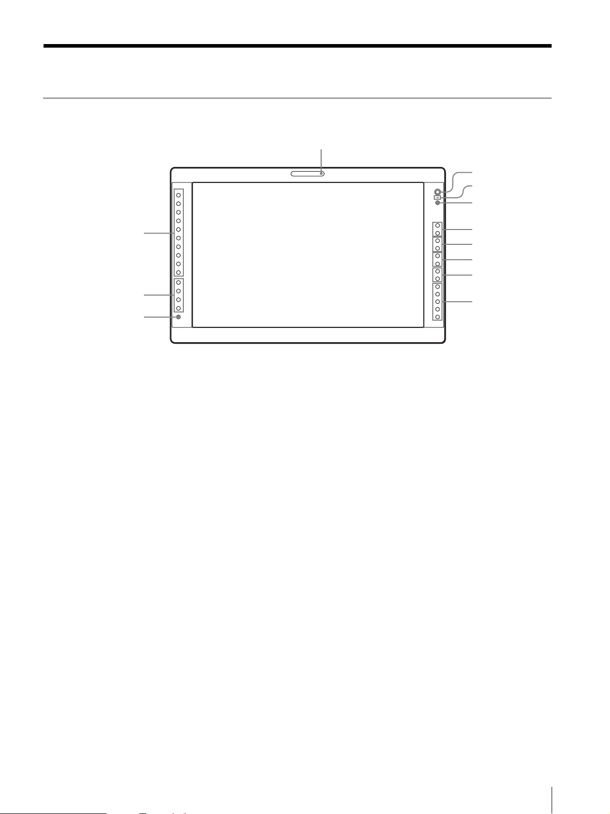
Location and Function of Parts and Controls
Front Panel
1
COMPOSITE
Y/C
RGB
0
qa
qs
COMPONENT
USER MEM
A-1
A-2
B-1
B-2
HD15
DVI
F1
F2
F3
F4
+
–
+
–
+
–
+
–
+
–
2
3
4
5
6
7
8
9
a Tally lamp
You can check the status of the monitor by the color of
the tally lamp.
The tally lamp lights in green according to the setting of
PARALLEL REMOTE in the REMOTE menu.
b Power indicator
When the power is turned on, the power indicator lights
in green.
c - (key inhibit) indicator
Lights in green when KEY INHIBIT in the KEY
INHIBIT menu is set to ON.
d CONTROL button
Press to display the buttons on the front panel. Press
again to clear the display.
e CONTRAST buttons
Adjusts the picture contrast.
Press the + button to make the contrast higher or the –
button to make it lower.
f PHASE buttons
Adjusts color tones.
Press the + button to make the skin tones greenish or the
– button to make them purplish.
g CHROMA buttons
Adjusts the color intensity.
Press the + button to increase the color intensity or the –
button to decrease it.
h BRIGHT (brightness) buttons
Adjusts the picture brightness.
Press the + button to increase the brightness or the –
button to decrease it.
i Menu operation buttons
Displays or sets the on-screen menu.
MENU button
Press to display the on-screen menu.
Press again to clear the menu.
+/– buttons
Press to select the items and setting values.
ENTER button
Press to confirm a selected item on the menu.
To display the signal format
When the menu is not displayed and the button is
pressed, the recognized signal format is displayed.
RETURN button
When the menu is displayed and the button is pressed,
the value of an item is reset to the previous value.
Also, when the fan stops, this button blinks.
To display the names of functions assigned to the
function buttons
When the menu is not displayed and the button is
pressed, the function selected in FUNCTION
BUTTON SETTING of the USER CONFIG menu
is displayed on the side of the F1 to F4 button.
Location and Function of Parts and Controls
13

j Input select buttons
Press the button to monitor the signal input to each
connector.
A-1, A-2, B-1 and B-2 buttons are used when an
optional input adaptor has been installed in the option
port.
COMPOSITE button: to monitor the signal through
the COMPOSITE IN connector
Y/C button: to monitor the signal through the Y/C IN
connector
RGB button: to monitor the RGB signal through the
connectors for the R/G/B signal input
COMPONENT button: to monitor the component
signal through the connectors for Y/P
B/PR signal input
A-1 button: to monitor the signal from connector 1
of the input adaptor installed in the option port A or R/
G/B signal from BKM-229X/BKM-256DD installed
in the option port A
A-2 button: to monitor the signal from connector 2
of the input adaptor installed in the option port A or Y/
P
B/PR signal from BKM-229X/BKM-256DD
installed in the option port A
B-1 button: to monitor the signal from connector 1
of the input adaptor installed in the option port B or R/
G/B signal from BKM-229X/BKM-256DD installed
in the option port B
B-2 button: to monitor the signal from connector 2
of the input adaptor installed in the option port B or Y/
P
B/PR signal from BKM-229X/BKM-256DD
installed in the option port B
HD15 button: to monitor the signal through the
HD15 input connector
DVI button: to monitor the signal through the DVI-D
input connector
k Function buttons
You can turn the assigned function on or off.
The factory setting is as follows;
F1 button: EXT SYNC
F2 button: SCAN
F3 button: ASPECT
F4 button: MULTI DISPLAY
You can assign a function from among SCAN, ASPECT,
EXT SYNC, BLUE ONLY, MONO, MULTI DISPLAY,
DISPLAY LAYOUT, SUB INPUT SELECT,
POSITION, FRAME, APA, I/P MODE, MIRROR
IMAGE, AUTO SYNC DETECT and FLICKER FREE
via FUNCTION BUTTON SETTING in the USER
CONFIG menu (see page 31).
For details of the function assigned to the function
button, see page 31.
l USER MEM (user memory) button
Press to load the picture settings saved in the USER
MEMORY menu (on page 35).
14
Location and Function of Parts and Controls
 Loading...