

Sony STR-DE1015G, STR-DE815G, TR-DE1015G Operating Instructions Manual

© 1997 by Sony Corporation
3-860-819-12(1)
Operating Instructions
STR-DE1015G
STR-DE815G
STR-D760Z
FM Stereo
FM-AM Receiver
2
WARNING
To prevent fire or shock hazard, do
not expose the unit to rain or
moisture.
For customers in the U.S.A.
This symbol is intended to alert the user
to the presence of uninsulated
“dangerous voltage” within the
product’s enclosure that may be of
sufficient magnitude to constitute a risk
of electric shock to persons.
This symbol is intended to alert the user
to the presence of important operating
and main maintenance (servicing)
instructions in the literature
accompanying the appliance.
INFORMATION
This equipment has been tested and
found to comply with the limits for a
Class B digital device, pursuant to Part
15 of the FCC Rules.
These limits are designed to provide
reasonable protection against harmful
interference in a residential installation.
This equipment generates, uses, and can
radiate radio frequency energy and, if
not installed and used in accordance
with the instructions, may cause harmful
interference to radio communications.
However, there is no guarantee that
interference will not occur in a particular
installation. If this equipment dose
cause harmful interference to radio or
television reception, which can be
determined by turning the equipment
off and on, the user is encouraged to try
to correct the interference by one or
more of the following measures:
- Reorient or relocate the receiving
antenna.
- Increase the separation between the
equipment and receiver.
- Connect the equipment into an outlet
on a circuit different from that to
which the receiver ifs connected.
- Consult the dealer or an experienced
radio/TV technician for help.
CAUTION
You are cautioned that any changes or
modification not expressly approved in
this manual could void your authority to
operate this equipment.
Note to CATV system installer
This reminder is provided to call CATV
system installer’s attention to Article
820-40 of the NEC that provides
guidelines for proper grounding and, in
particular, specifies that the cable
ground shall be connected to the
grounding system of the building, as
close to the point of cable entry as
practical.
Owner’s record
The model and serial numbers are
located on the rear of the unit.
Record the serial number in the space
provided below. Refer to them
whenever you call upon your Sony
dealer regarding this product.
Model No. STR-DE1015G
STR-DE815G
STR-D760Z
Serial No.
For customers in Canada
CAUTION
TO PREVENT ELECTRIC SHOCK,
DO NOT USE THIS POLARIZED
AC PLUG WITH AN EXTENSION
CORD, RECEPTACLE OR OTHER
OUTLET UNLESS THE BLADES
CAN BE FULLY INSERTED TO
PREVENT BLADE EXPOSURE.
This receiver incorporates the Dolby*
Pro Logic Surround system.
* Manufactured under license from
Dolby Laboratories Licensing
Corporation. “Dolby ,” the double-D
symbol a, “AC-3” and “Pro Logic”
are trademarks of Dolby Laboratories
Licensing Corporation.
Precautions
On safety
• Should any solid object or liquid fall
into the cabinet, unplug the receiver
and have it checked by qualified
personnel before operating it any
further.
On power sources
• Before operating the receiver, check
that the operating voltage is identical
with your local power supply. The
operating voltage is indicated on the
nameplate at the rear of the receiver.
• This unit is not disconnected from the
AC power source (mains) as long as it
is connected to the wall outlet, even if
the unit itself has been turned off.
• If you are not going to use the receiver
for a long time, be sure to disconnect
the receiver from the wall outlet. To
disconnect the AC power cord, grasp
the plug itself; never pull the cord.
• One blade of the plug is wider than
the other for the purpose of safety and
will fit into the wall outlet only one
way. If you are unable to insert the
plug fully into the outlet, contact your
dealer.
• AC power cord must be changed only
at the qualified service shop.
On placement
• Do not install the appliance in a
confined space, such as a bookcase or
built-in cabinet.
• Place the receiver in a location with
adequate ventilation to prevent heat
buildup and prolong the life of the
receiver.
• Do not place the receiver near heat
sources, or in a place subject to direct
sunlight, excessive dust or mechanical
shock.
• Do not place anything on top of the
cabinet that might block the
ventilation holes and cause
malfunctions.
On operation
• Before connecting other components,
be sure to turn off and unplug the
receiver.
On cleaning
• Clean the cabinet, panel and controls
with a soft cloth slightly moistened
with a mild detergent solution. Do not
use any type of abrasive pad, scouring
powder or solvent such as alcohol or
benzine.

3
For customers in the USA
For detailed safety precautions, see the
“IMPORTANT SAFEGUARDS” leaflet.
If you have any question or problem
concerning your receiver, please
consult your nearest Sony dealer.
About This Manual
The instructions in this manual are
for models STR-DE1015G, STRDE815G and STR-D760Z. Check
your model number by looking at
the upper right corner of the front
panel. Functionally, the main
difference between the models is that
the STR-DE1015G is equipped with a
Dolby Digital (AC-3) decoder and
the STR-DE815G and STR-D760Z are
not.
In this manual, the STR-DE1015G is
the model used for illustration
purposes, any difference in
operation is clearly indicated in the
text, for example, “STR-DE1015G
only.”
This manual is divided into three
sections; Getting Started, On-screen
Operations and Front Panel
Operations.
The “Getting Started” section
describes connections, how to set up
the remote for on-screen control, and
Dolby Surround.
The “On-Screen Operations” section
describes how to operate the receiver
using the remote to manipulate the
on-screen display on your TV screen.
The remote lets you perform almost
all of the receiver operations.
You can also control the receiver
without the remote. The “Front
Panel Operations” section describes
how to operate the receiver using the
front panel controls. In addition, for
the USA and Canadian models, this
section also explains how to use the
remote short-cut buttons.
The following icon is used in this
manual:
Indicates hints and tips for
making the task easier.
Table of contents
Welcome! 4
Hooking Up the System
Hookup Overview 5
Infrared (IR) Repeater Hookups 7
Antenna Hookups 7
Audio Component Hookups 8
Speaker System Hookups 9
TV/VCR Hookups 11
Digital Component Hookups (STR-DE1015G only) 13
AC Hookups 14
Setting Up the Remote for On-Screen Control
Using the Remote 15
Registering a TV (or Monitor) 17
Registering Audio and Video Components 19
Dolby Surround Setup
Dolby Digital (AC-3) (STR-DE1015G only) 22
Dolby Pro Logic (STR-DE815G and STR-D760Z) 24
Playback/Recording
Selecting a Component 26
Watching TV or Video Programs 28
Tuning and Presetting Radio Stations 29
Recording 31
Sound Adjustment
Using the Pre-programmed Sound Field 33
Customizing the Sound Fields 37
Additional Operations and Settings
Registering Desired Component (User IR setting) 42
Indexing 43
Playing Sources Automatically (Auto Play) 44
Starting a Source Automatically at Power On (Auto Start) 44
Starting Several Components in Sequence Automatically
(Macro Play) 45
Adjusting the Sensitivity of the Remote 46
Changing the Display Settings 46
Using the Sleep Timer 48
Operating a CD Changer 48
Front Panel Operations (Remote Short-cuts: USA and Canada only)
Front Panel Descriptions 51
Remote Descriptions 52
Selecting a Component 53
Tuning Radio Stations 54
Recording 55
Adjusting the Sound 55
Customizing the Receiver Operations 57
Indexing 59
Playing Audio Sources Without the TV (Flasher)
(except for USA and Canada) 60
Additional Information
Troubleshooting 61
Specifications 63
Glossary 65
Index (Back Cover)
Getting Started
On-Screen Operations
Front Panel Operations
z
4
Welcome!
3
1
º‚
¢
¢
¢
¢
≠±
·
∏π
FUNCTION
USERSUBINPUT
SETUPSOUND
()0pP=+
2
Â
µ
Mm
Video signal
Thank you for purchasing the STR-DE1015G, STRDE815G or STR-D760Z Sony FM Stereo/FM-AM
Receiver.
Your new receiver is an audio/video control center
with a unique interface. When you connect the
receiver to your TV, an on-screen display (shown
below) appears and lets you operate the various
connected audio/video components with this
receiver’s remote.
Also, the on-screen display lets you control any other
device that can be controlled by an infrared remote
control, such as air conditioners.
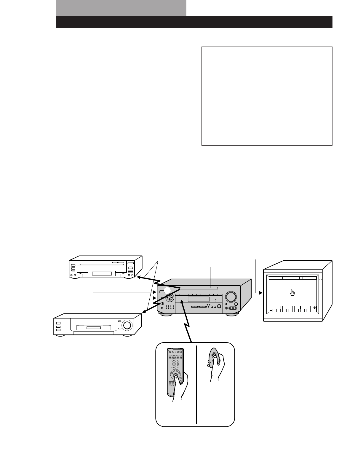
Understanding How the Receiver Works
1 The remote emits an infrared (IR) signal when you
press direction control button (see 1 below).
2 This controls the movement of the pointer (hand-
shaped icon) in the on-screen display (see 2 below).
3 When you move the pointer to an on-screen icon,
and press the center of the direction control button
on the remote, the infrared (IR) emitter on the front
panel transmits the corresponding IR control code to
the respective component (see 3 below).
For USA
and Canada
(RM-H501)
For other
countries
(RM-VR101)
TV (monitor)
Video signal (Input from source
components combined with on-screen
display)
STR-DE1015G
IR emitter
IR receptor
IR control codes
LD player, etc.
VCR, etc.
Video signal
About the color system for video input
This unit is compatible with the following color
systems.
USA and Canadian model : NTSC
Australian model : PAL*
Singaporean model : PAL*
Other countries : NTSC
* Although the normal OSD is displayed in color, when
video signals are input from other components the
OSD is displayed in black and white.
5
Hooking Up the System
DIGITAL
IR OUT
S-LINK
TV/DBS VIDEO2
MONITOR
WOOFER
SURROUND SPEAKERS
WIRELESS
REAR
SPEAKER
AC OUTLET
IMPEDANCE USE 8-16Ω
FRONT SPEAKERS
VIDEO 1
ANTENNA
PHONO
CD TAPEDAT / MD
IMPEDANCE
SELECTOR
LD/
DVD
Speaker System Hookups (9)
* DBS receivers can be used with USA, Canadian and Australian models only.
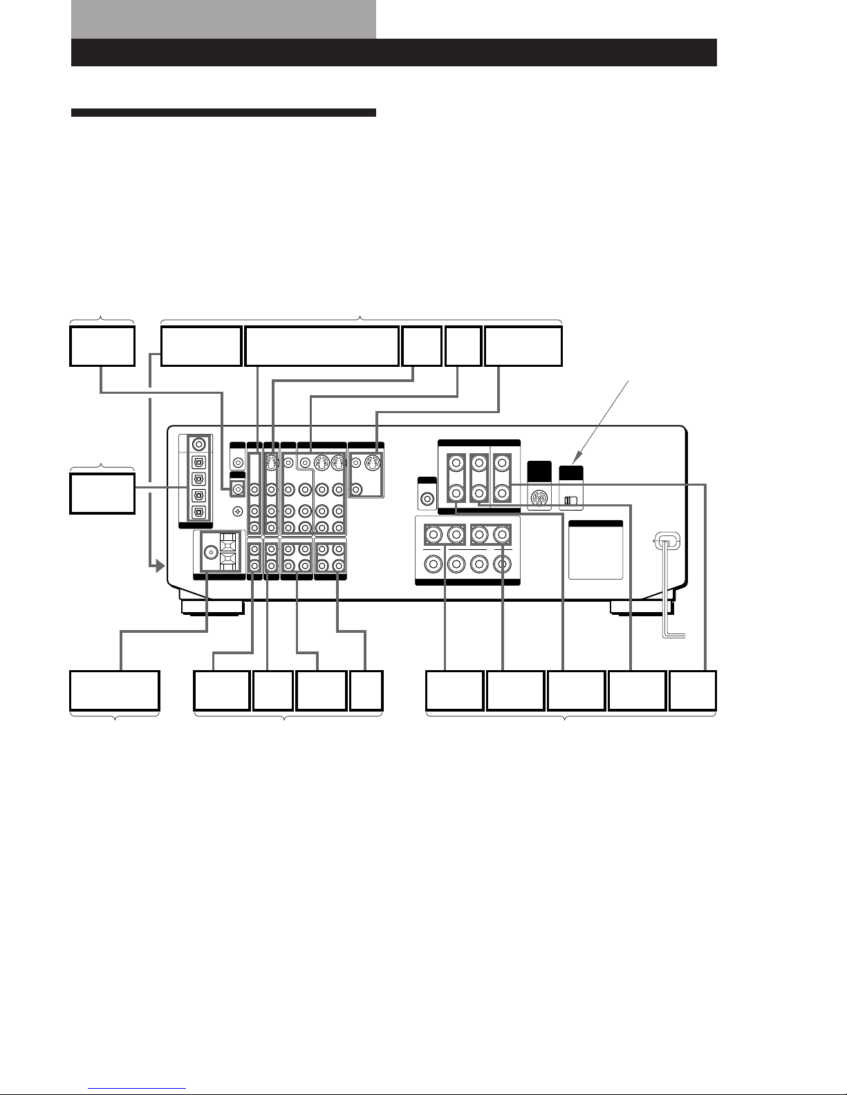
Hookup Overview
The receiver allows you to connect and control the
following audio/video components. For details on
connection of each component, see the pages in
parentheses.
p STR-DE1015G
Infrared (IR) Repeater
Hookups (7)
TV/VCR Hookups (11)
Digital
Component
Hookups (13)
Antenna Hookups (7) Audio Component Hookups (8)
IR Repeater
Video camera/
video game
TV tuner/Digital Broadcasting
Satellites (DBS) receiver*
LD/DVD
player
VCR TV/MONITOR
DVD player
(etc.)
AM/FM antenna
CD
player
DAT/MD
deck
Tape
deck
Front
speaker (R)
Front
speaker (L)
Rear
speaker (R)
Rear
speaker (L)
Center
speaker
Turntable
Except for
Singaporean model
To the
front panel
6
Hooking Up the System
5-1 INPUT
IR OUT
S-LINK
TV/DBS VIDEO2
MONITOR
SURROUND SPEAKERS
WIRELESS
REAR
SPEAKER
AC OUTLET
IMPEDANCE USE 8-16Ω
FRONT SPEAKERS
VIDEO 1
ANTENNA
PHONO
CD TAPEDAT / MD
WOOFER
LD/
DVD
IMPEDANCE
SELECTOR
Before you get started
• Check that you received the following items with the
receiver:
- FM wire antenna (1)
- AM loop antenna (1)
- Remote commander (remote) (1)
(remote for USA and Canada: RM-H501)
(Remote for other countries: RM-VR101)
- Size AA (R6) batteries (2)
- IR repeater (1)
- Video Cable (1)
(USA and Canadian models only)
- Control S cable for TV (1)
(USA and Canadian models only)
• Turn off the power to all components before making
any connections.
• Do not connect the AC power cords until all of the
connections are completed.
• Be sure to make connections firmly to avoid hum
and noise.
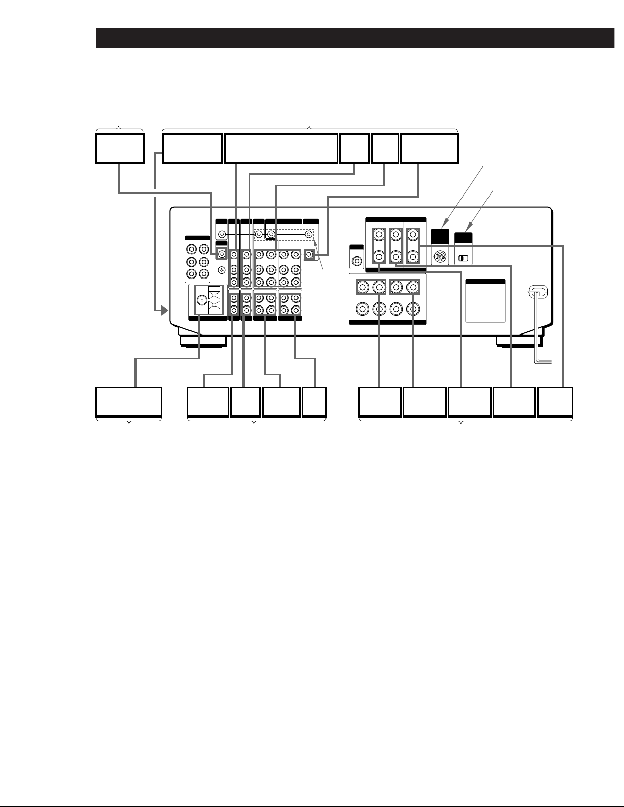
p STR-DE815G and STR-D760Z
Speaker System Hookups (9)
* DBS receivers can be used with USA, Canadian and Australian models only.
Infrared (IR) Repeater
Hookups (7)
TV/VCR Hookups (11)
Antenna Hookups (7) Audio Component Hookups (8)
IR Repeater
Video camera/
video game
TV tuner/Digital Broadcasting
Satellites (DBS) receiver*
LD/DVD
player
VCR
TV/MONITOR
AM/FM antenna
CD
player
DAT/MD
deck
Tape
deck
Front
speaker (R)
Front
speaker (L)
Rear
speaker (R)
Rear
speaker (L)
Center
speaker
Turntable
STR-DE815G only
Except for
Singaporean model
To the
front panel
STR-DE815G
USA and
Canada only
7
Getting StartedHooking Up the System
Antenna Hookups
You can receive radio broadcasts by connecting FM
and AM antennas.
Connecting an outdoor antenna
We recommend that you connect an outdoor antenna
for better reception. Connect an optional FM outdoor
antenna for FM.
Important
If you connect an outdoor antenna, ground it against
lightning. To prevent a gas explosion, do not connect the
ground wire to a gas pipe.
Notes
• Do not use the y SIGNAL GND for this connection.
• To prevent noise pickup, keep the AM loop antenna away
from the receiver and TV.
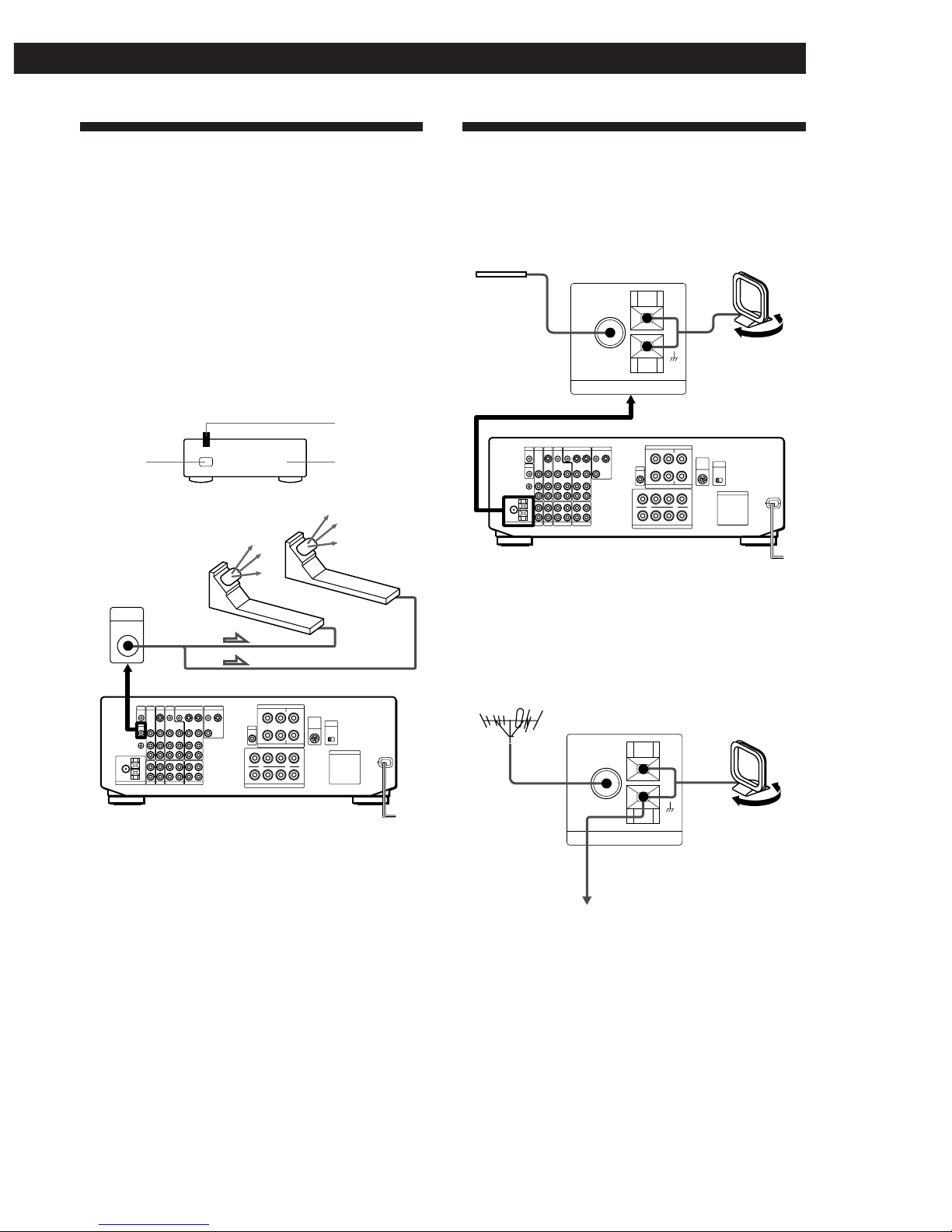
Infrared (IR) Repeater Hookups
The IR repeater emits infrared signals corresponding to
those emitted by the remote controls supplied with the
components. Connect the IR repeater if:
• You experience difficulty controlling a certain
component using the on-screen display control.
• Your installation configuration prevents the IR
repeater on the receiver’s front panel from reaching
all of the components you need to control.
After connecting the IR repeater, set it above or below
the IR sensor on the component(s) to be controlled.
Each IR repeater can send infrared signals to one
component.
Note
Use the supplied adhesive tape to secure the IR repeater so
that its front faces the component to be controlled.
infrared
signals
µ
IR OUT
IR repeater(s)
IR sensor
IR repeater
75-ohm
coaxial cable
(not supplied)
FM wire antenna
(supplied)
Extend the
FM wire
antenna
horizontally.
AM
FM
75Ω
COAXIAL
ANTENNA
AM
FM
75Ω
COAXIAL
ANTENNA
AM loop antenna
(supplied)
Adjust the
direction.
FM outdoor antenna
(not supplied)
Ground wire
(not supplied)
to ground
Component
8
Hooking Up the System
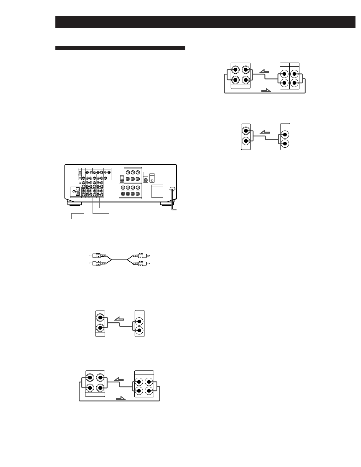
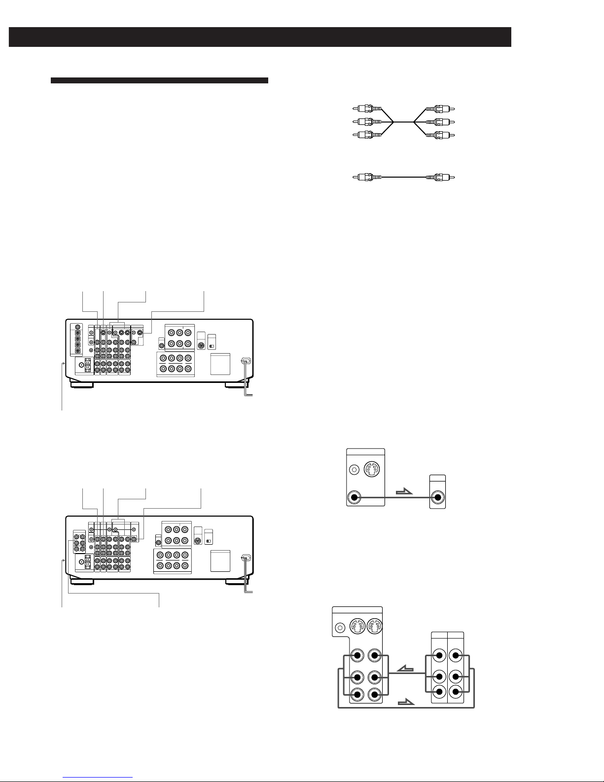
Audio Component Hookups
You can use the receiver as an amplifier by completing
these connections.
If your components are Sony products, connect them to
the jacks as shown in the table on page 19 so that the IR
registration is unnecessary.
Note for STR-DE1015G
For digital connections see “Digital Component Hookups”
(page 13).
What cords will I need?
Audio cord (not supplied)
Ç : signal flow
a CD (to CD player)
b TAPE (to a tape deck)
c DAT/MD (to DAT/MD deck)
d PHONO (to a turntable)*
* If your turntable has an earth lead, connect it to y
SIGNAL GND on the unit to prevent hum.
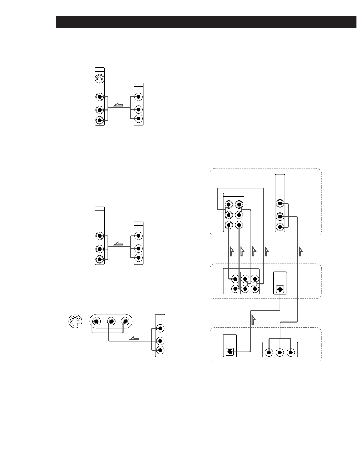
z To use Sony components with a CONTROL A1
terminal
You can connect a CONTROL A1 compatible Sony CD
player, tape deck or MD deck to the receiver. Use a
CONTROL A1 cord (not supplied) to connect the CTRL
A1 jack on each component to the S-LINK CTRL A1 jack
on the receiver. See the instructions for each
component.
z You can display the operating status of the
component connected to the CTRL A1 jack
See page 58 for DTR-DE1015G.
See page 59 for STR-DE815G.
z To use a Sony CD changer with a COMMAND MODE
selector
• If the changer does not have a VIDEO OUT jack, set
the command mode to “CD 1” and connect the
changer to the CD jack on the receiver.
• If the changer has a VIDEO OUT jack, set the
command mode to “CD 2” and connect the changer
to the VIDEO 1, VIDEO 2, or LD jack on the receiver.
Receiver
S-LINK/CTRL A1
d PHONO a CD c DAT/MD b TAPE
White (L)
Red (R)
White (L)
Red (R)
OUTPUT
LINE
L
R
IN
CD
CD player
L
R
RECOUT IN
TAPE
OUTPUT
LINELINE
L
R
INPUT
Receiver
Tape deck
RECOUT IN
DAT / MD
L
R
OUTPUT
LINELINE
L
R
INPUT
OUTPUT
LINE
L
R
IN
PHONO
Receiver
Turntable
Receiver
DAT/MD
9
Getting StartedHooking Up the System
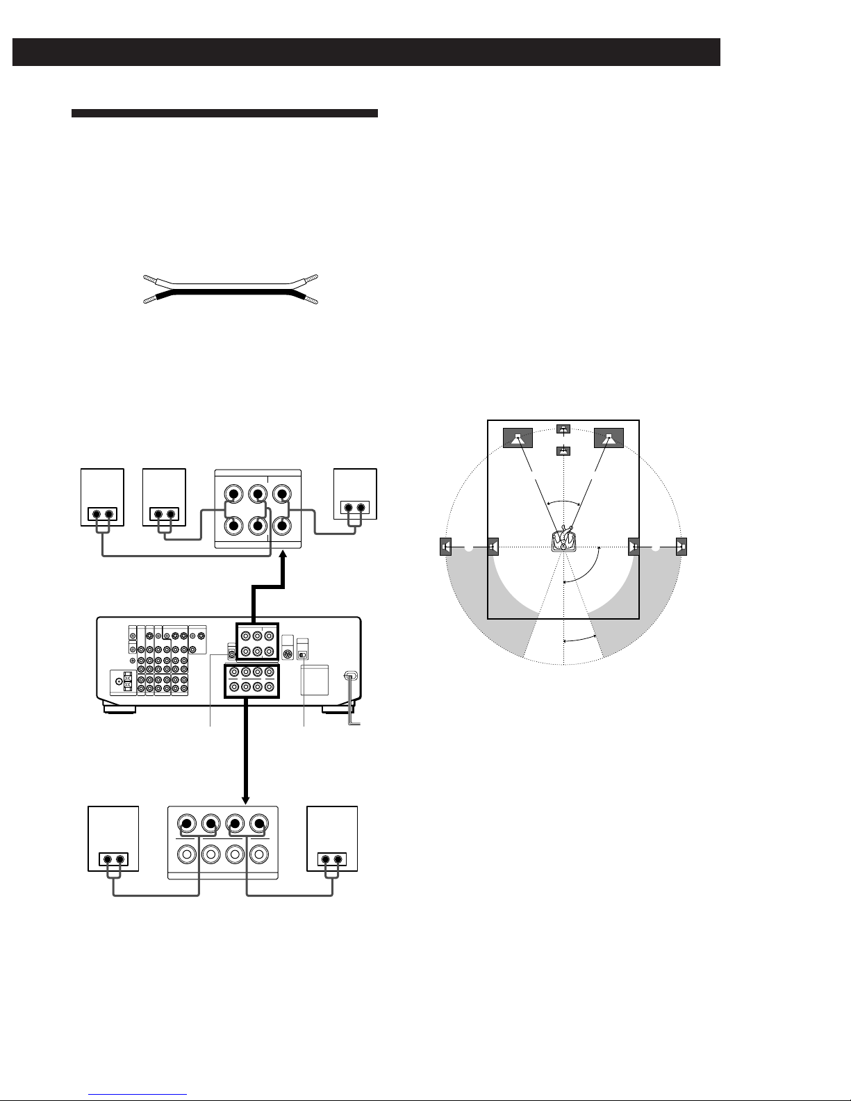
Speaker System Hookups
Although front (left and right) speakers are required,
center and rear speakers are required only for enjoying
surround sound.
What cords will I need?
Speaker cord (not supplied)
Twist the stripped ends of the cord about 2/3 inch (15
mm). Be sure to match the speaker cord to the
appropriate terminal on the components: + to + and –
to –. If the cords are reversed, the sound will be
distorted and will lack bass.
Speaker placement for STR-DE1015G
Normally, to obtain the best possible surround sound
all speakers should be placed the same distance from
your listening position (A).
This unit, however, allows you to place the center
speaker closer (B), so that is lines up with the front
speakers. The rear speakers can also be placed closer
(C), according to the shape of your room.
If you feel that this placement reduces the surround
effects, you can adjust the center and rear delay
parameters to obtain the effect you desire (see page 39).
Note
To take full advantage of Dolby Digital (AC-3) surround
effects we reccommend using high quality speakers. We also
reccommend using front, center, and rear speakers that are
of the same size and quality.
Notes
• Do not place the center or rear speakers father away from
the listening position than the front speakers.
• When mounting the rear speakers on side walls
perpendicular to the listening position they should be
placed 60 - 90 cm (24 - 35 inches) above the listening
position (as shown in “Speaker placement for STRDE815G and STR-D760Z” on page 10).
(+)
(–)
Rear
speaker (L)
(+)
(–)
IMPEDAMCE USE 8-16Ω
USE IMPEDANCE 4-16Ω
A
++--
++--
R
B
A
L
B
FRONT SPEAKERS
REAR CENTER
RL
R
+
-
+
-
L
SURROUND SPEAKERS
Rear
speaker (R)
Receiver
Center
speaker
WOOFER
AUDIO
OUT
IMPEDANCE
SELECTOR
Front speaker (R) Front speaker (L)
45°
90°
20°
A A
B
CC
10
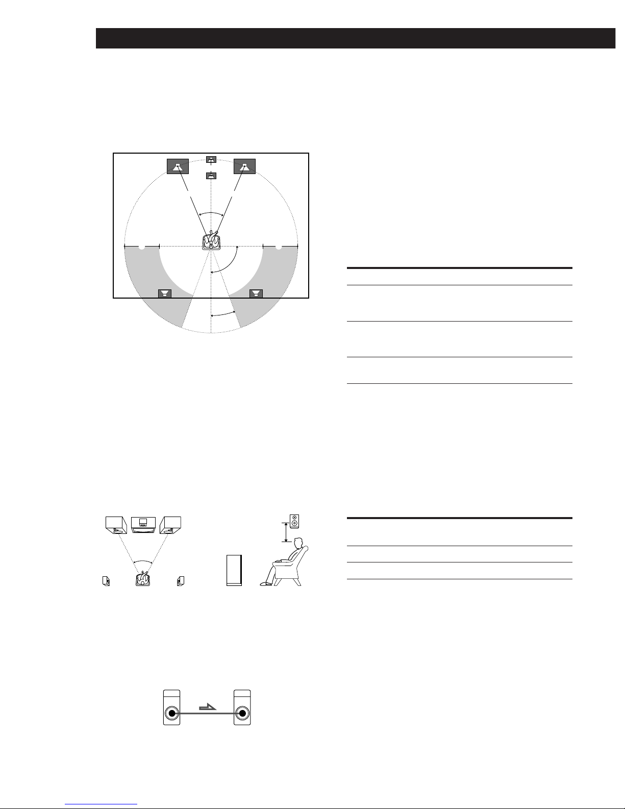
Hooking Up the System
Depending on the shape of your room (etc.), you may
wish to place the rear speakers behind you instead of
on the side walls. One advantage of this placement is
that you can use a pair of large floor standing speakers
matching your front speakers.
Note
If you place the rear speakers behind you, be sure to check
the rear speaker position setting in the SPEAKER SETUP
before using the VIRTUAL MULTI REAR and VIRTUAL
REAR SHIFT sound fields (see pages 22 and 33 to 34 for
details).
Speaker placement for STR-DE815G and
STR-D760Z
For optimum surround sound effect, place your
speakers as shown below.
z You can connect an active woofer
You can reinforce the bass sound by connecting an
optional active woofer to the WOOFER AUDIO OUT
terminal.
z You can connect wireless rear speakers
(except for STR-D760Z)
When using an optional Sony wireless rear speaker
system, connect the transmitter to the WIRELESS REAR
SPEAKER connector.
Note
Do not connect any other components to the WIRELESS
REAR SPEAKER connector.
Selecting the speaker system
You can connect one set or two sets of speakers. Set the
SPEAKERS selector on the front panel according to
your speaker system.
To drive Set SPEAKERS selector to
Speaker system A A
(connected to the FRONT
SPEAKERS A terminals)
Speaker system B B
(connected to the FRONT
SPEAKERS B terminals)
Both speaker systems A and B A+B*
(parallel connection)
* Connect speakers with nominal impedance of 8 ohms, or
higher, to the A and B terminals.
Selecting the impedance (except for
Singaporian models)
Check the impedance of your speakers (usually
indicated on the back of the speaker), and set the
IMPEDANCE SELECTOR for the front speakers.
If nominal impedance of Set IMPEDANCE SELECTOR
your speaker is your speaker is to
Between 4 and 8 ohms 4 Ω
8 ohms or higher 8 Ω
Active woofer
Front speaker
45°
90°
20°
A A
B
CC
Rear speaker
60 - 90 cm
(2 - 3 feet)
AUDIO
OUT
WDOFER INPUT
Receiver
11
Getting StartedHooking Up the System
TV-VCR Hookups
You must connect a TV to control the receiver using the
on-screen display. Also, to enjoy the Dolby Pro Logic
Surround encoded videos and TV programs, you need
to connect TV and VCRs together with the center and
rear speakers.
If your components are Sony products, connect them to
the jacks as shown in the table on page 19, this makes
IR registration is unnecessary.
p STR-DE1015G
For digital connections see “Digital Component
Hookups” (page 13)
p STR-DE815G and STR-DE760Z
* TV/DBS : USA, Canada and Australia
TV : Other countries
What cables will I need?
• Audio/video cable (not supplied)
• Video cable (not supplied)
Make sure to match the color of the plugs and the
jacks: Yellow (video) to Yellow; White (left, audio) to
White; and Red (right, audio) to Red. If your
components have S-video jacks, we recommend that
you use the S-video jacks instead of the video jacks.
Ç : signal flow
a MONITOR (to TV or monitor)
Be sure to use your TV as a monitor, and use the TV
tuner built-in to the VCR to watch TV programs. If
you use your TV’s tuner, the on-screen display will
change to a TV program when you switch channels.
Also, do not connect anything to the TV/DBS* IN
jacks.
If you connect a Sony TV with TV OUT jacks, you can
use the TV tuner in your TV (see page 28 for details)
and the TV/DBS IN jacks without disrupting the onscreen display.
b VIDEO 1, 2 (to VCR)
Connect VCRs to the VIDEO 1 or/and VIDEO 2 jacks.
If you connect a Sony StarSight tuner, connect it to the
VIDEO 1 jacks.
d TV/DBS*
5.1 INPUT
Yellow
b VIDEO 1, 2 a MONITOR
e VIDEO 3 INPUT
(on the front panel)
c LD/DVD
d TV/DBS* b VIDEO 1, 2 a MONITOR
e VIDEO 3 INPUT
(on the front panel)
c LD/DVD
White (L)
Red (R)
Yellow
White (L)
Red (R)
Yellow Yellow
Receiver
Monitor
S-LINK
CTRL S
VIDEO
OUT
MONITOR
INPUT
S-VIDEO
IN
OUT
L
R
S-LINK
CTRL S
VIDEO
OUT
AUDIO
OUT
VIDEO
IN
AUDIO
IN
VIDEO 1
OUTPUT
VIDEO VIDEO
AUDIO AUDIO
L
R
INPUT
S-VIDEO S-VIDEO
OUT
OUT IN
Receiver
VCR
12
Hooking Up the System
Receiver
c LD/DVD (to LD or DVD player)
Note for STR-DE815G and STR-D760Z
To input decoded Dolby Digital (AC-3) soundtracks, make
connections as shown below in “Playing decoded Dolby
Digital (AC-3) soundtracks”.
d TV/DBS* (to TV tuner or Digital Broadcasting
Satellites (DBS) receiver)
e VIDEO 3 INPUT (to a video camera or a video game)
* TV/DBS : USA, Canada and Australia
TV : Other countries
z If you have a CONTROL S compatible monitor or VCR
(for USA and Canada only)
Use a CONTROL S cord (supplied) to connect the CTRL
S IN (for monitor) or CTRL S OUT (for VCR) jack on the
receiver to the appropriate S-LINK jack on the
respective component. Refer to the Operating
Instructions supplied with your monitor or VCR for
details.
Note
Set the TV tuner to skip channels where there is no broadcast
so that an image is always displayed on the TV screen;
otherwise, the on-screen display is distorted.
Playing decoded Dolby Digital (AC-3)
soundtracks (STR-DE815G and STR-D760Z)
If you have a Dolby Digital (AC-3) decoder, you can
use the receiver to amplify decoded Dolby Digital (AC-
3) soundtracks with the following connections. These
audio signals are paired with the video signals input to
the LD/DVD VIDEO IN jack (see page 27 for details
regarding operation).
VIDEO
IN
AUDIO
IN
LD/
DVD
L
R
OUTPUT
VIDEO
AUDIO
L
R
S-VIDEO
IN
VIDEO
IN
AUDIO
IN
TV/DBS
L
R
OUTPUT
VIDEO
AUDIO
L
R
Receiver
TV tuner/DBS
VIDEO L AUDIO R
VIDEO 3 INPUT
L
R
OUTPUT
VIDEO
AUDIO
Receiver
(front panel)
Video camera/
video game
LD/DVD
>
STR-DE1015G
only
Receiver
Dolby Digital (AC-3)
decoder (etc.)
DVD player
FRONT
L
R
REAR
CENTER
WOOFER
5-1 INPUT
CENTER
WOOFER
REAR FRONT
PRE OUT
OUT
DIGITAL
IN
DIGITAL
VIDEO
IN
AUDIO
IN
LD/
DVD
L
R
LINE OUT
R L VIDEO- AUDIO -
13
Getting StartedHooking Up the System
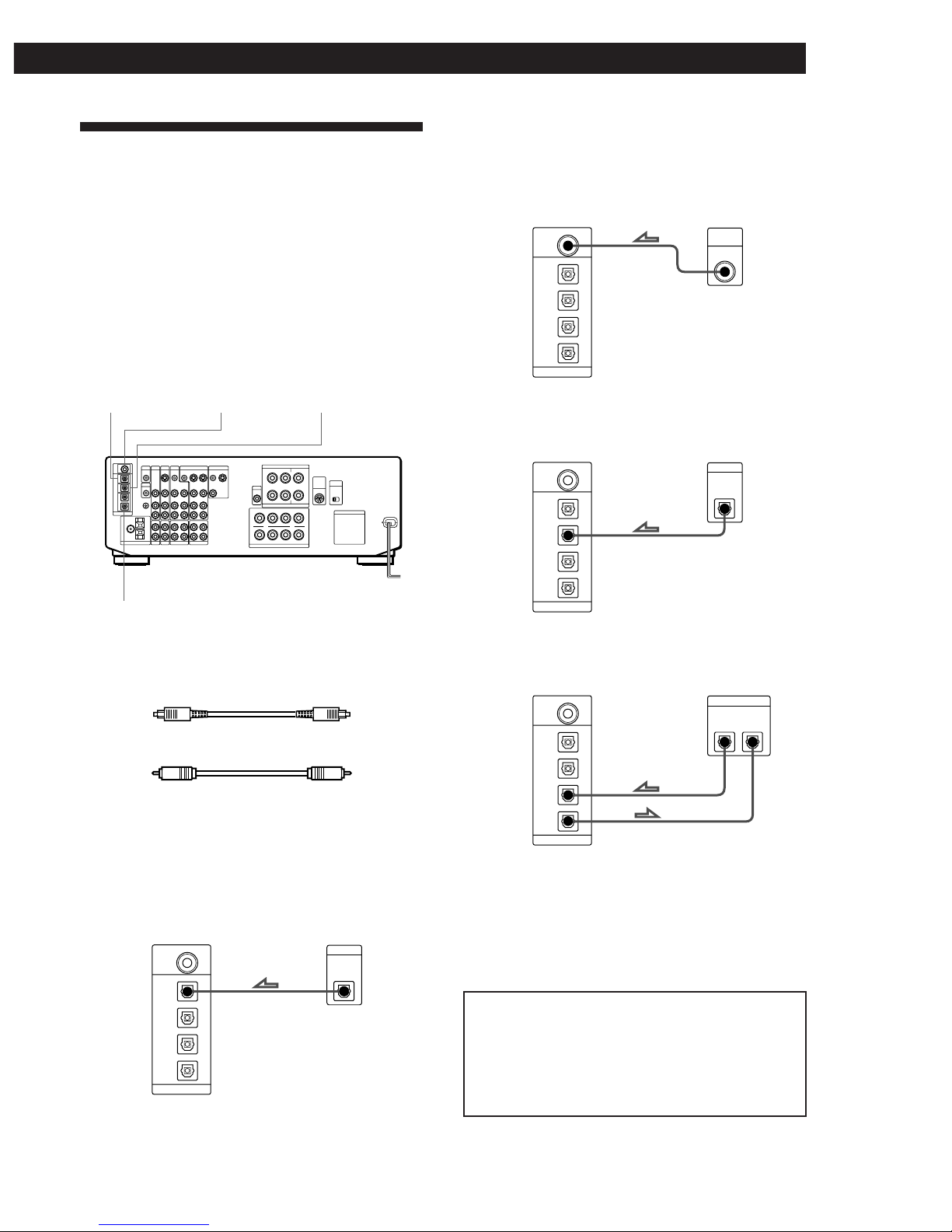
Digital Component Hookups
(STR-DE1015G only)
You can connect the optical digital output jack of a
DVD player, DAT/MD deck, CD player (etc.) to the
receiver’s optical digital input jacks.
You can also connect the AC-3 RF output terminal of
an LD player to the receiver’s AC-3 RF input terminal.
You can connect the receiver’s optical digital output
jack to a DAT/MD deck.
After making digital connections, also be sure to select
the appropriate INPUT MODE (see page 27 for details).
What cords will I need?
• Optical digital connecting cord (not supplied)
• Coaxial digital connection cord (not supplied)
Ç : signal flow
a LD/DVD IN: OPTICAL (to DVD player)
If you connect a DVD player to the analog LD/DVD in
jacks, be sure to connect the DVD player’s optical
digital output to the LD/DVD IN : OPTICAL jack.
d DAT/MD IN (OUT): OPTICAL
a LD/DVD: OPTICAL b LD/DVD: RF c CD IN: OPTICAL
b LD/DVD IN: AC-3 RF (to LD player)
If you connect an LD player to the analog LD/DVD in
jacks, be sure to connect the LD player’s AC-3 RF
output to the LD/DVD IN: AC-3 RF jack.
c CD IN: OPTICAL (to CD player)
d DAT/MD IN(OUT):OPTICAL (to DAT or MD deck)
Note
This unit is only compatible with digital components using
32 kHz/44.1 kHz/48 kHz sampling frequencies. It is not
compatible with 96 kHz.
DAT/MD OUT
DIGITAL
OPTICAL
DAT/MD IN
OPTICAL
CD IN
OPTICAL
LD/DVD IN
OPTICAL
LD/DVD IN
AC-3
RF
OUT
DIGITAL
Receiver DVD player
Receiver LD player
DAT/MD OUT
DIGITAL
OPTICAL
DAT/MD IN
OPTICAL
CD IN
OPTICAL
LD/DVD IN
OPTICAL
LD/DVD IN
AC-3
RF
OUT
AC-3
RF
Receiver CD player
DAT/MD OUT
DIGITAL
OPTICAL
DAT/MD IN
OPTICAL
CD IN
OPTICAL
LD/DVD IN
OPTICAL
LD/DVD IN
AC-3
RF
OUT
DIGITAL
DAT/MD OUT
DIGITAL
OPTICAL
DAT/MD IN
OPTICAL
CD IN
OPTICAL
LD/DVD IN
OPTICAL
LD/DVD IN
AC-3
RF
OUT
DIGITAL
IN
Receiver DAT/MD deck
Warning regarding the playback of DAT/MD sources
When playing DAT/MD sources through this unit, do
not play a DAT/MD that contains digital recordings
made from a DVD player whose digital output was set to
“DOLBY DIGITAL”. High volume noise will be output
which may damage this unit or your speakers.
Hooking Up the System
14
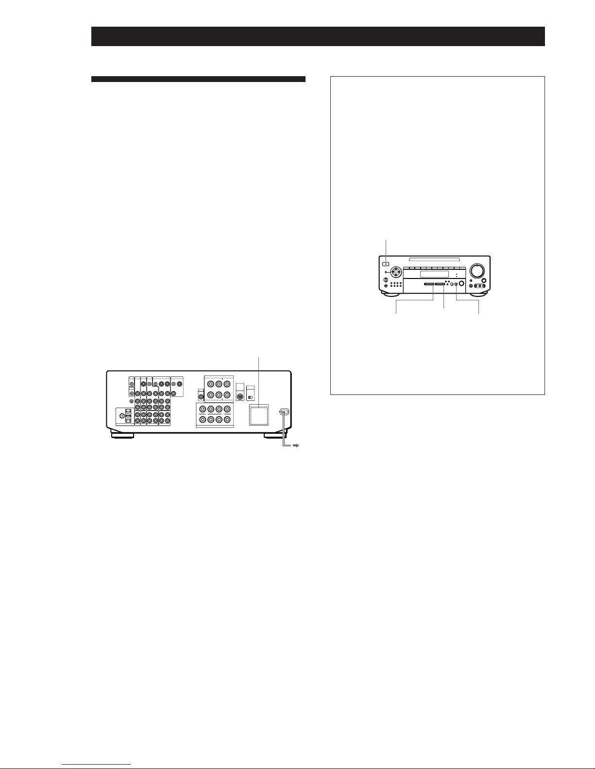
AC Hookups
Setting the voltage selector (only on the
models supplied with the voltage selector)
Check that the voltage selector on the rear panel of the
receiver is set to the local power supply voltage. If not,
set the selector to the correct position using a
screwdriver before connecting the AC power cord to a
wall outlet.
Connecting the AC power cord
Connect the AC power cord from this receiver and
from your audio/video components to a wall outlet.
If you connect other audio components to the
SWITCHED AC OUTLET(s) on the receiver, the
receiver can supply power to the connected
components so you can turn on/off the entire system
when you turn on/off the receiver.
Caution
Make sure that the power consumption of the component(s)
connected to the receiver’s AC outlet(s) does not exceed the
wattage indicated on the rear panel. Do not connect highwattage electrical home appliances such as electric irons,
fans, or TVs to this outlet.
to a wall
outlet
SWITCHED AC OUTLET(s)
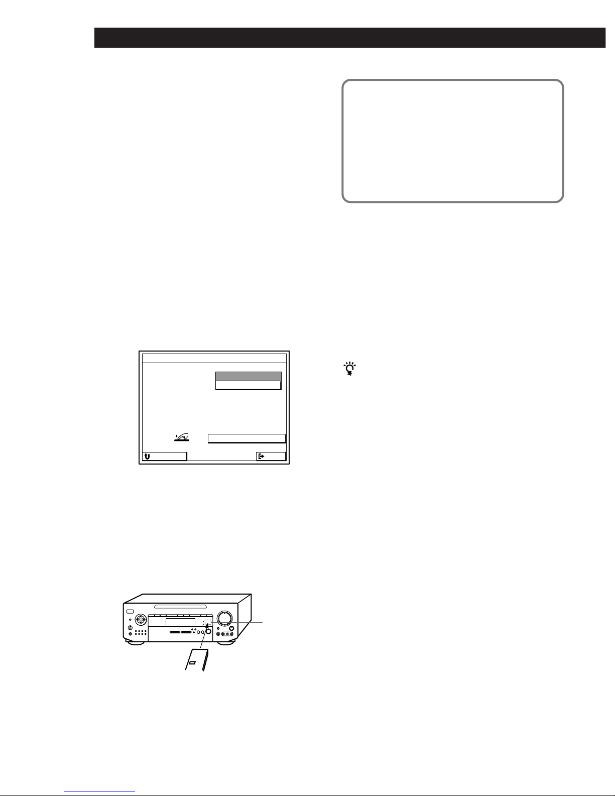
Before using for the first time
Be sure to clear the receiver’s memory before using
for the first time.
1 Make sure the POWER is set to off.
2 While holding down the VIDEO FUNCTION >,
AUDIO FUNCTION > and SOUND FIELD
MODE buttons, press POWER to turn on the
receiver.
“ALL CLEAR!” appears in the display.
Note
Clearing the receiver’s memory erases all preset radio
stations and IR code settings etc.
POWER
VIDEO
FUNCTION
>
AUDIO
FUNCTION
>
SOUND FIELD
MODE
15
Setting Up the Remote for On-Screen Control
PUSH
ENTER
º‚
¢
¢
¢
¢
≠±
·
∏π
¢
¢
¢
¢
Using the Remote
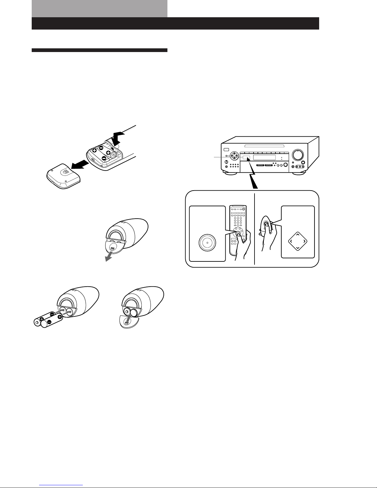
Inserting batteries into the remote (USA
and Canada)
Insert two size AA (R6) batteries with the + and – on
the battery compartment. When using the remote,
point it at the remote sensor g on the receiver.
Inserting batteries into the remote (other
countries)
1 Open the cover on the
bottom of the remote.
2 Insert two size AA (R6) batteries with correct
polarity (+/–), then close the cover.
Notes on the remote
Battery life
Under normal use, the batteries should last for about 6
months. When the remote no longer operates the receiver,
replace both batteries with new ones.
Notes
• Do not leave the remote in an extremely hot or humid
place.
• Do not use a new battery with an old one.
• Do not expose the remote sensor to direct sunlight or
lighting apparatuses. Doing so may cause a malfunction.
• If you don’t use the remote for an extended period of time,
remove the batteries to avoid possible damage from
battery leakage and corrosion.
Turning on the receiver and bringing up the
on-screen display on your TV (or monitor)
To turn on the receiver, point the remote at the IR
receptor, and then press the direction control button on
the remote once or twice. To bring up the on-screen
display, turn on your TV and set it to the appropriate
video input. If you register the IR code of your TV (see
“Registering a TV (or Monitor)” on page 17), you can
turn on your TV automatically whenever you turn on
the receiver.
IR receptor
(continued)
For USA and Canada
For other countries
Direction
control
button
Direction
control
button
b
16
Setting Up the Remote for On-Screen Control
FUNCTION
USERSUBINPUT
SOUND
()0pP=+
PUSH
ENTER
Mm
Â
µ
º‚
¢
¢
¢
¢
≠±
·
∏π
¢
¢
¢
¢
Mm
Â
µ
SETUP
Blank
area
IR emitter
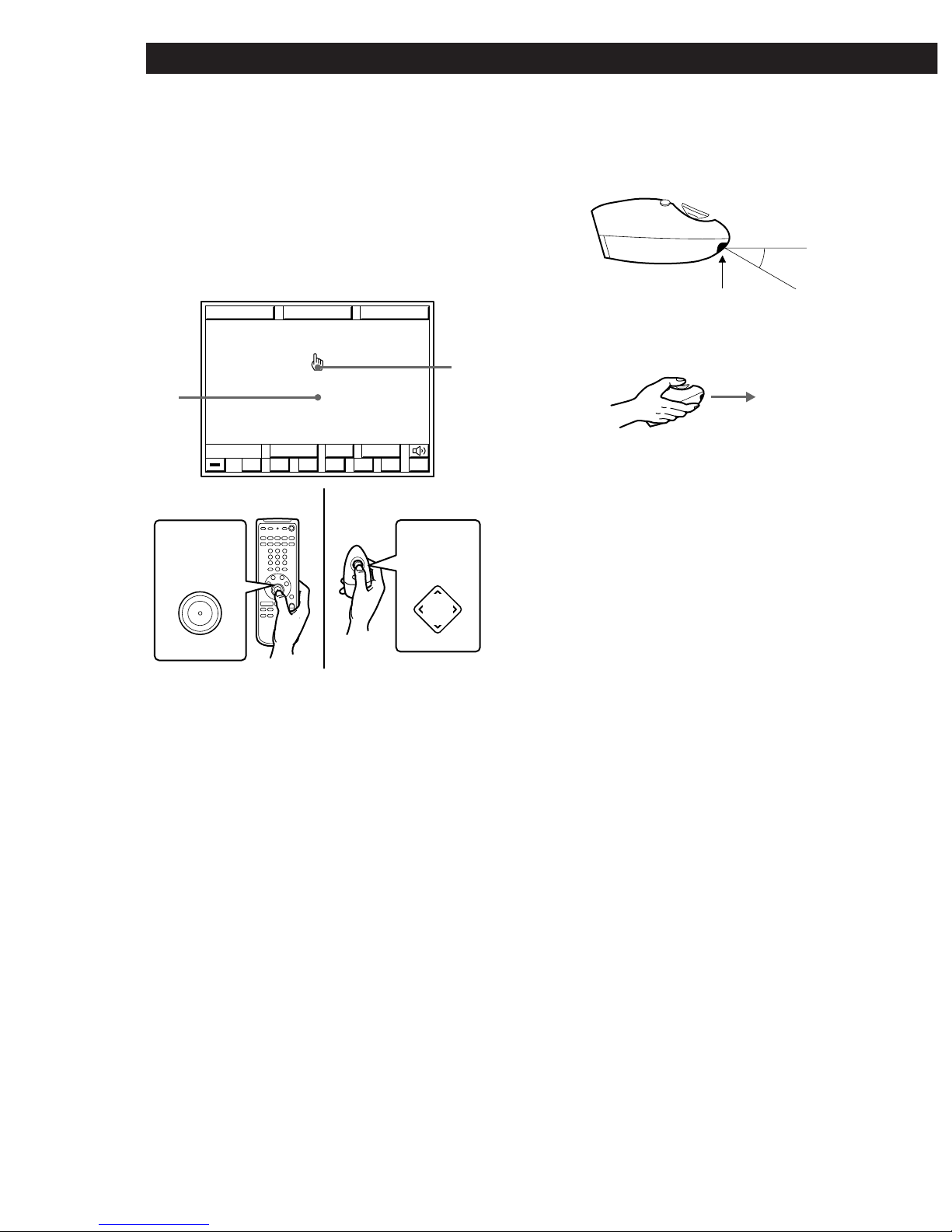
How to use the remote
The supplied remote lets you perform almost all of the
receiver operations.
This section describes how to use the direction control
button. For certain operations, you can also control the
receiver using the other (short-cut) buttons instead of
the direction control button.
For details, see page 52.
1 Press the direction control button on the remote
once to recall the on-screen display.
2 Press repeatedly (or hold down) the corner of the
direction control button (M, m, Â, µ) in the
direction you want to move the pointer (handshaped icon) on the on-screen display.
3 To “click” on an item, position the pointer so that
it is on one of the on-screen items, then press and
quickly release the center of the direction control
button (indicated by “PUSH ENTER”).
To make the on-screen display disappear
Position the pointer in the blank area, and press the center of
the direction control button.
• For USA and Canada : You can also turn the on-screen
display on or off by pressing GUI.
Direction
control
button
Direction
control
button
Notes on handling the remote (except for USA and
Canada)
• Do not cover the IR emitter on the remote when operating
the remote.
• Hold the remote with its direction control button facing
up, as shown below.
Pointer
For USA and Canada
For other countries
30°
17
Getting StartedSetting Up the Remote for On-Screen Control
Registering a TV (or Monitor)
You must register the IR code of your TV (or monitor)
in order to turn on your TV automatically whenever
you turn on the receiver.
IR code registration is unnecessary in the
following case
If your TV is a Sony product that can be controlled by
an infrared remote, and it is connected to the receiver
by its VIDEO 1 video input jack, you do not need to
register its IR code.
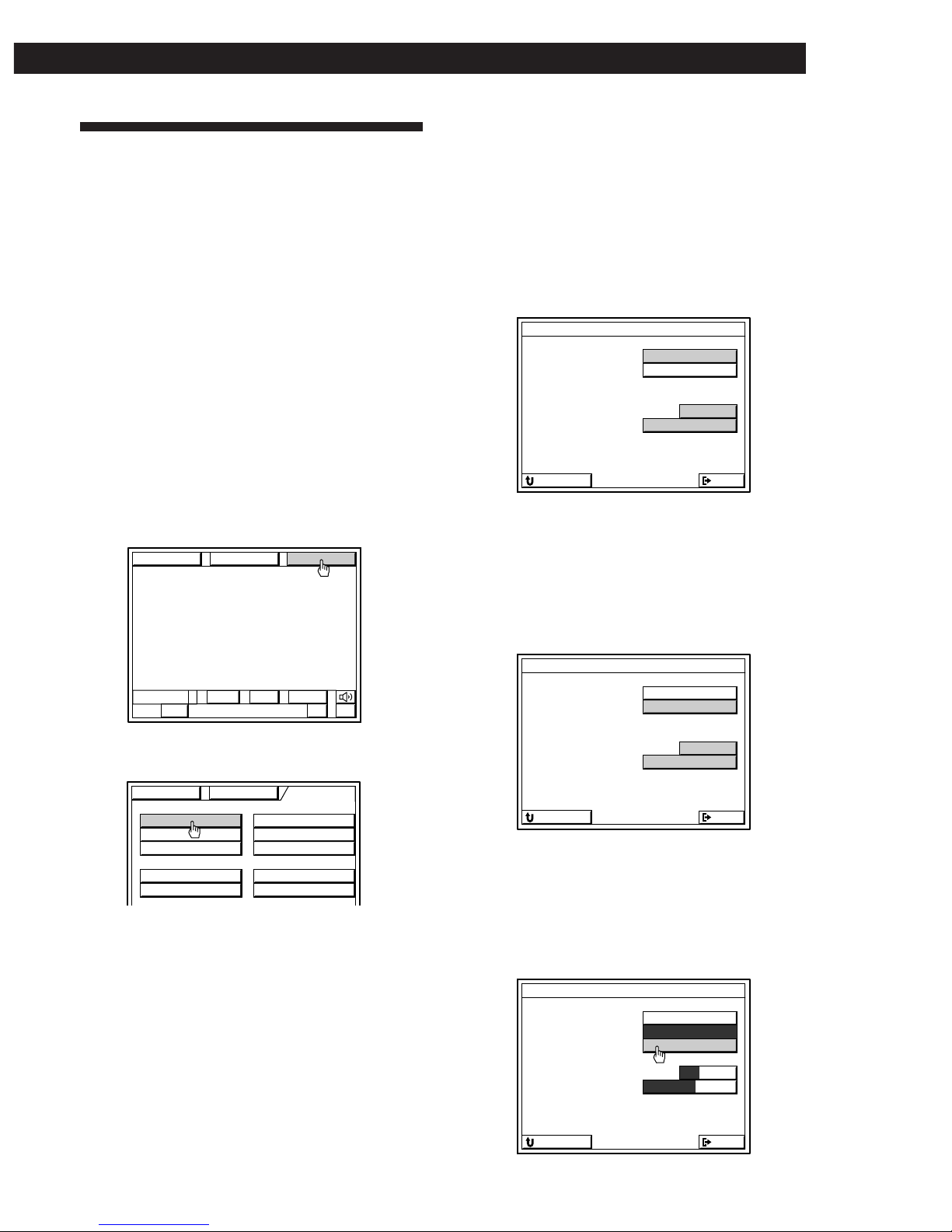
Registering IR codes
1 Turn on the receiver and the TV.
Make sure the input selector on the TV is set to
the video input.
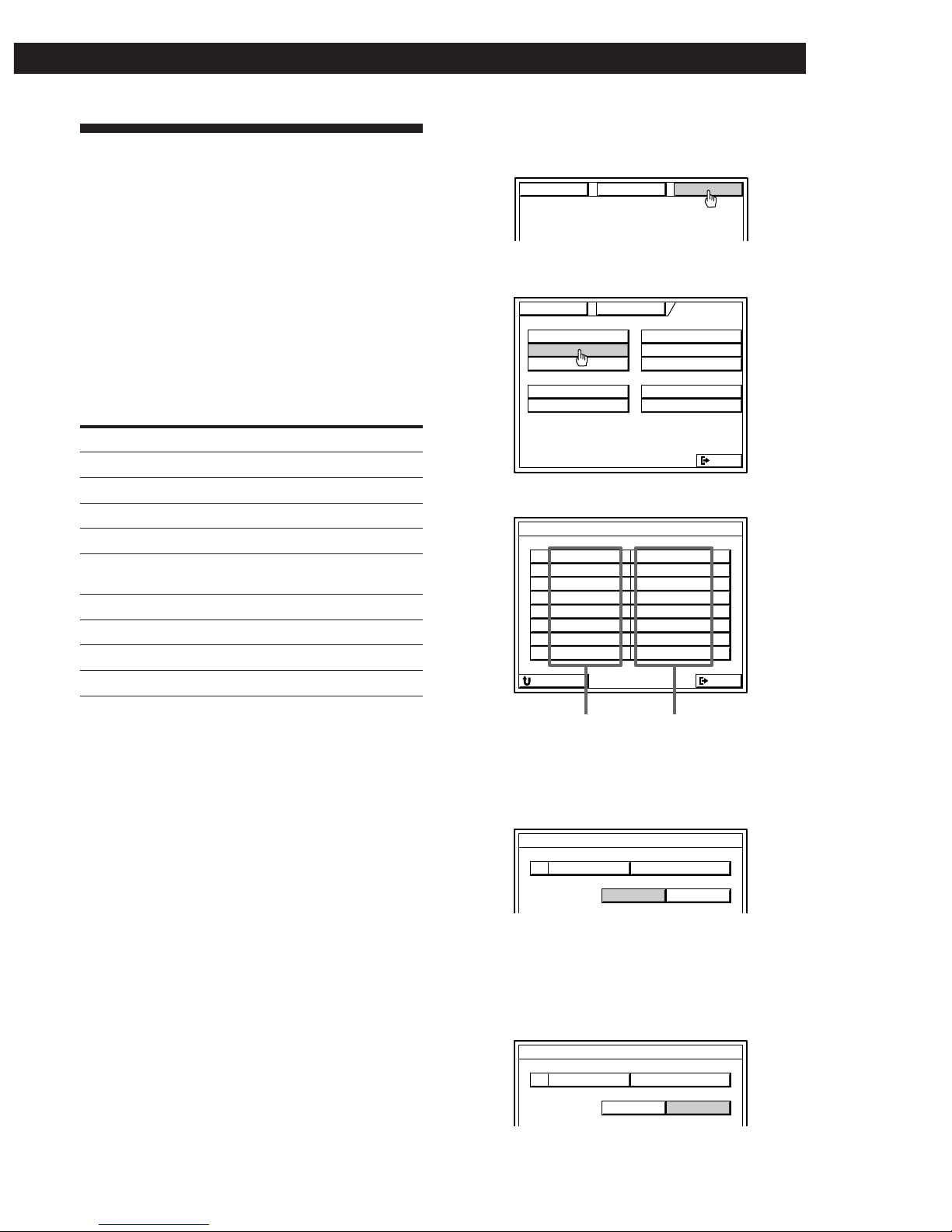
2 Click SETUP in the main menu.
3 Click TV SET.
4 • Sony TV
1 Click Sony TV.
2 Click VIDEO 1, 2 or 3 to select the video
input of the TV that is connected to the
receiver.
3 If your TV type is a wide screen type (screen
ratio:16 x 9), click WIDE (except for Australian
and Singaporean models).
The IR codes are automatically registered
and registration is complete.
• Non-Sony TV
1 Click OTHER TV.
2 Click VIDEO 1, 2 or 3 to select the video input
of the TV that is connected to the receiver.
3 If you are using a wide TV, click WIDE (except
for Australian and Singaporean models).
4 Go to step 5.
5 Cover the IR sensor on the TV to prevent
accidental operation. Otherwise, the on-screen
display may be turned off during the registration
procedure.
6 Click START.
(continued)
USERSUBLIST
+–
BAND
FM 102.50MH
z STEREO
FUNCTION SOUND SETUP
TV FUNC
CD
IR
TUNER
USER IR
SET
SET
INDEX
INDEX
INDEX
AUTO START SLEEP TIMER
OSD SETUP
MACRO PLAY
FUNCTION SOUND SETUP
TV MONITOR SET
TV IR SET
Sony TV
OTHER TV
NORMAL WIDE
1
VIDEO
32
TV SIZE
TV INPUT
EXITRETURN
TV MONITOR SET
TV IR SET
Sony TV
OTHER TV
NORMAL WIDE
1
VIDEO
32
TV SIZE
TV INPUT
EXITRETURN
TV MONITOR SET
TV IR SET
START
Sony TV
OTHER TV
NORMAL WIDE
1
VIDEO
32
TV SIZE
TV INPUT
EXITRETURN
18
Setting Up the Remote for On-Screen Control
7 When “PUSH YOUR REMOTE” appears in the
on-screen display, press the button on the TV's
remote that corresponds to the highlighted
control button (e.g., POWER).
• If your TV’s remote has an independent input
selector button (e.g., VIDEO 1).
Register the IR code of this button when the VIDEO 1
button appears. When you turn on the receiver, the
TV switches to the video input automatically.
• If your TV does not have an independent input
selector button or has a cyclic input selector
button.
Do not register an IR code of the input selector
button. The TV’s input cannot be switched
automatically when you turn on the receiver. Switch
the TV to the video input manually. If you registered
an IR code for the VIDEO 1 button, erase the VIDEO 1
code following the steps in “To erase a specific IR
code” below.
• If you selected WIDE in step 4.
Register the IR code for the wide TV mode button on
your TV’s remote when the WIDE TV DISPLAY
MODE button appears.
For Australian and Singaporean models
The on-screen display also includes the following
settings for your TV's remote control.
• TV/VIDEO : Use to program the cyclic input selector
button on your TV’s remote. This allows you to
switch the TV’s input selector using this unit’s
remote. Do not program an independant input
selector button at this setting.
• WIDE TV DISPLAY MODE: Use to program the wide
TV mode button on your TV’s remote.
When registering the IR code, be sure to do the
following; otherwise, the IR code may not be
registered correctly.
• Point the remote at the IR sensor on the
receiver from a distance of less than 2 inches (5 cm).
• Hold down the button on the remote for about 2 or 3
seconds until the “RECEIVING” display switches to
“RELEASE YOUR REMOTE”.
• Keep the remote pointed horizontally at the IR sensor
until the code is registered.
8 Repeat step 7 for the remaining buttons that
appear in the on-screen display.
If “NG” is displayed, an IR code was not
registered correctly. In this case, repeat step 7
again.
To return to the main menu
Click EXIT.
To return to a previous menu
Click RETURN.
To exchange from a non-Sony TV to a Sony TV
Connect the receiver’s MONITOR OUT jack to the
VIDEO 1 input jack of the Sony TV. Follow the
registration steps 1 to 3, then click SONY TV in step 4.
Click VIDEO 1 2 3 and/or WIDE to specify VIDEO 1
and/or WIDE if necessary.
Note
Some IR codes may not have been successfully registered,
even if “RELEASE YOUR REMOTE” appears on the TV
screen. In this case, try registering the IR code again. If the
IR code still cannot be registered, follow the procedure
described in “Registering Desired Components (User IR
setting)” on page 42.
Erasing TV IR codes
Click CODE CLEAR in the TV IR SET menu that
appears when you click START.
• To erase a specific IR code
1 Click SINGLE IR CODE CLEAR.
2 Click the button you want to clear.
“Are you sure?” appears.
3 Click YES to erase the code.
To cancel erasing, click NO.
To erase another code repeat steps 2 and 3.
• To erase all the TV IR codes
1 Click TV IR CODE CLEAR.
“Are you sure?” appears.
2 Click YES to erase the codes.
“CODE CLEAR!” appears in the display.
To cancel erasing, click NO.
IR sensor
TV's remote
TV IR SET
TV IR SET
TV POWER
VIDEO 1
PUSH YOUR REMOTE
CODE CLEAR
EXITRETURN
19
Getting StartedSetting Up the Remote for On-Screen Control
Registering IR codes
1 Click SETUP in the main menu.
2 Click IR SET.
3 Click the name of the receiver's jack you want.
4 • Sony product
Click Sony.
The IR codes are automatically registered and
registration is complete.
To take advantage of CONTROL-A1 compatible audio
components, such as multi-disc CD players, click
CONTROL-A1 to select CONTROL-A1.
• non-Sony product
Click OTHER.
Registering Audio and Video
Components
You must register the IR code of your audio/video
component to control your component using the onscreen display.
IR code registration is unnecessary in the
following case
If your audio/video component is a Sony product that
can be controlled by an infrared remote, and it is
connected to the jacks shown in the following table,
you do not need to register the IR code.
Receiver jacks Component to be connected
VIDEO 1 Sony VTR 3 (VHS)
VIDEO 2 Sony VTR 1 (BETA)
VIDEO 3 Sony VTR 2 (8 mm)
LD/DVD Sony LD player
TV/DBS Sony DBS receiver (USA, Canada and
Australia only)
DAT/MD Sony DAT deck
CD Sony CD player (CD 1)
TAPE Sony Tape deck
MONITOR Sony TV (via its VIDEO 1 jack)
The following cases require registration of Sony products
• When connecting a Sony MD deck to the DAT/MD
jacks.
• When connecting a Sony audio product with
CONTROL-A1 compatibility.
• When connecting a Sony product to jacks other than
those specified in the previous table (e.g., when
connecting a Sony LD player to the VIDEO 3 jacks).
• When exchanging a non-Sony audio or video
component with a Sony product.
Notes
• If your VCR has a COMMAND CODE selector switch (for
VTR1, VTR2, or VTR3), set the switch to the applicable
setting. If your VCR has a built-in StarSight tuner, you
must set the COMMAND CODE selector switch to VTR 3.
• If your CD changer has a COMMAND MODE selector
switch (for CD 1, CD 2, or CD 3), normally it should be set
to “CD 1.” However, if your CD changer has VIDEO OUT
terminals, set the command mode to “CD 2” or “CD 3”
(“CD 3” should be used only when making CONTROL-A1
connections).
Receiver's jacks
Connected
component
(continued)
FUNCTION SOUND SETUP
TV FUNC
CD
IR
TUNER
USER IR
EXIT
SET
SET
INDEX
INDEX
INDEX
AUTO START SLEEP TIMER
OSD SETUP
MACRO PLAY
FUNCTION SOUND SETUP
OTHERMAKER
IR CODE SETTING
Sony
OUTPUT IR
VIDEO 1 Sony VTR3
Sony VTR1
Sony VTR2
TV/DBS
TAPE
Sony TAPE
DAT/MD Sony DAT
CD Sony CD1
Sony DBS
Sony LD
IR CODE SETTING
VIDEO 2
VIDEO 3
LD/DVD
EXITRETURN
OTHERMAKER
IR CODE SETTING
Sony
OUTPUT IR
20
Setting Up the Remote for On-Screen Control
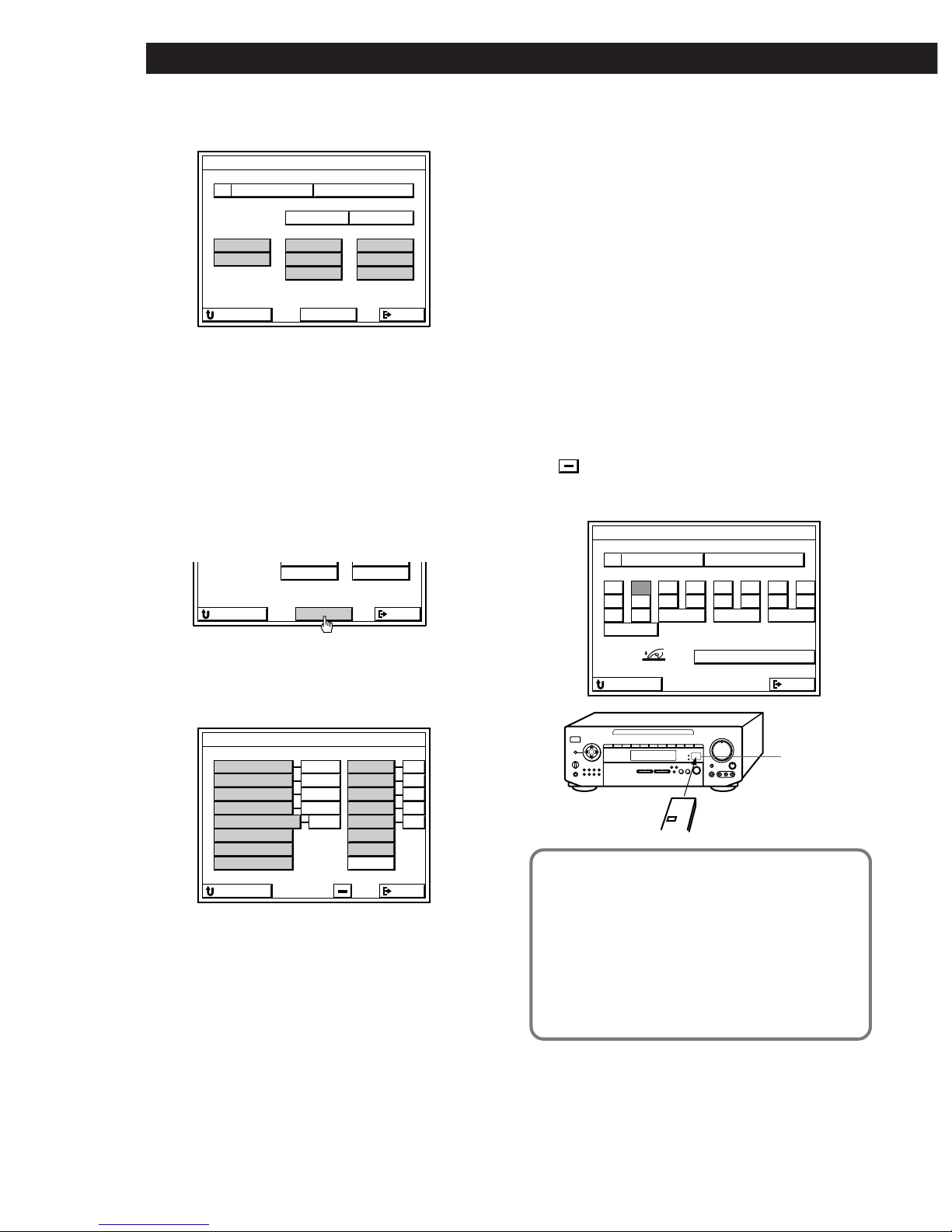
5 Click the respective component.
• If the component is not a VCR or laser disc
player
1 Cover the IR sensor on the component to
prevent accidental operation during the
registration procedure.
2 Click START, then go to step 6.
• If the component is a VCR, DVD or laser disc
player:
1 Click START.
A list of other manufacturers appears.
2 Click the manufacturer of the component you
want.
The IR codes for that component are
automatically registered.
If the manufacturer is not listed, cover the IR
sensor on the component to prevent accidental
operation during the registration procedure,
click OTHER, then go to step 6.
3 Click TEST.
If the selected component turns on, the IR
codes have been registered. The registration is
complete.
If the component does not turn on:
Click the number button beside the
manufacturer’s name to select another number,
then click TEST again.
If the component still does not turn on:
Cover the IR sensor on the component to
prevent accidental operation during the
registration procedure is complete, click
OTHER, then go to step 6.
6 When “PUSH YOUR REMOTE” appears, press
the button on your audio/video component's
remote that corresponds to the control button
highlighted.
is the POWER switch.
After you have registered all the IR codes, the IR CODE
SETTING menu reappears.
When registering the IR code, be sure to do the
following; otherwise, the IR code may not be
registered correctly.
• Point the remote at the IR sensor on the
receiver from a distance of less than 2 inches (5 cm).
• Hold down the button on the remote for about 2 or 3
seconds until the “RECEIVING” display switches to
“RELEASE YOUR REMOTE”.
• Keep the remote pointed horizontally at the IR sensor
until the code is registered.
7 Repeat steps 3 to 6 to register IR codes from other
components.
audio/video component's
remote
IR sensor
OTHERMAKER
IR CODE SETTING
TAPE
DAT
DVD
LD
CD
VCR
MD
Sony
START
OUTPUT IR
EXITRETURN
TV
DATLD
CD
MD
START
EXITRETURN
VCR MAKER SETTING
EMERSON
TEST
EXITRETURN
FISHER
PANASONIC
TOSHIBA
MITSUBISHI
GRUNDIG
HITACHI
PHILIPS
AKAI
GE
JVC
RCA
SANYO
SHARP
ZENITH
OTHER
1 2
1 2
1 2
1 2
1 2
1 2 3 4
1 2 3
1 2
1 2
1 2 3
IR CODE SETTING
1
9
2
10/0
3
>10
4
DISC
5 6 7 8
)(0pP=+
PUSH YOUR REMOTE
CODE CLEAR
EXITRETURN
TRACK ENTER
D. SKIP

21
Getting StartedSetting Up the Remote for On-Screen Control
To return to the main menu
Click EXIT.
To return to a previous menu
Click RETURN.
To register special IR codes that do not appear as onscreen controls
See “Registering Desired Components (User IR setting)” on
page 42.
Notes
• If the IR codes do not operate as expected, perform the
registration operation(s) again to make sure the IR codes
are registered correctly. If the IR code still cannot be
registered, see “Registering Desired Components (User IR
setting)” on page 42.
• If you experience difficulty operating the INPUT, number,
or ENTER buttons of a VCR or LD player after automatic
registration in step 5, register the IR codes for that
component manually as shown in step 6.
• When using components made by other manufacturers,
certain operations may not be possible even after selecting
manufacturer (in step 5). In this case, register the IR codes
for those buttons manually as shown in step 6.
• If you register a playback source as TOSHIBA 2 or RCA 2,
you cannot turn the TV on or off using the receiver’s
remote (the power will not go on when you click TEST).
• Do not register the same type of component (e.g., an LD
player) at several different functions.
• You can register about 200 IR codes, including user IR
codes (see page 42); however, depending on the type of
codes recorded, the maximum limit may be less than 100.
It may be difficult or impossible to register about 200
codes under the following conditions:
-When registering from remotes with weak batteries.
-When registering IR codes that have been registered to a
programmable remote (e.g., any IR code not originally
supplied in the respective remote).
• Keep the IR sensor away from fluorescent light or direct
sunlight. Otherwise, the IR codes may not be registered.
• If the AC power cord is disconnected for about two
weeks, the registered IR codes will be erased. “ALL
CLEAR!” will appear on the TV screen the next time you
turn on the receiver.
• Some remote controls supplied with audio and video
components made by other manufacturers may have a
special formats. In such cases, it may not be possible for
the receiver to learn (or properly execute) their command
codes.
Erasing IR codes
Click CODE CLEAR in the IR CODE SETTING menu
that appears when you click START.
• To erase a specific IR code
1 Click SINGLE IR CODE CLEAR.
“SELECT CLEAR CODE KEY” appears.
2 Click the button you want to clear.
“Are you sure?” appears.
3 Click YES to erase the code.
“CODE CLEAR!” appears.
To cancel erasing, click NO.
To erase another code repeat steps 2 and 3.
• To erase all the IR codes for the current component
(e.g., OTHER CD)
1 Click (OTHER CD) CODE CLEAR.
“Are you sure?” appears.
2 Click YES to erase the codes.
“CODE CLEAR!” appears.
To cancel erasing, click NO.
• To erase all the IR codes
1 Click ALL IR CODE CLEAR.
“Are you sure?” appears.
2 Click YES to erase the codes.
“CODE CLEAR!” appears.
To cancel erasing, click NO.
 Loading...