

Page 1

Integrator Training
Digital Cinema Deployment
TMS Hardware Integrator Installation
Training Manual (CHIPS)
October 15
Page 2

Integrator Training, UK
Confidential Digital Cinema Deployment 2 of 49
October 15
CHIPS Stand-Alone Integrator Installation Training (CHIPS)
Document History
The following table details the revision history for this document.
Date Description of Changes Author Issue /
Version
06/12/2010 Original Chris Mullins 1.0
24/10/2011 Revised Chris Mullins 2.0
07/02/2012 Revised Chris Mullins 4.0
10/02/2012 Revised Chris Mullins 5.0
05/04/2012 Revised – Drawings / Section 11.1 / minor changes Chris Mullins 6.0
13/07/2012 Revised – For new Server Image Andrew Buckland 7.0
23/07/2012 Revision Andrew Buckland 8.0
28/01/2013 Updated and edited Andrew Buckland 8.2
01/09/2015 Updated and edited Chris Mullins 8.4
Confidentiality
This document and any attachments have been prepared b y Sony Professional S olutions Europe for the sole use
of integrator being trained. The contents are confidential and must not be communicated in whole or part to a ny
other party without the prior written approval of Sony.
© 2010 Sony Professional Solutions Europe. All rights reserved.
Page 3

Integrator Training, UK
Confidential Digital Cinema Deployment 3 of 49
October 15
CHIPS Stand-Alone Integrator Installation Training (CHIPS)
Contents
TMS HARDWARE INTEGRATOR INSTALLATION TRAINING (CHIPS) 1
1 S
CHEMATICS 5
1.1 CHIPS Rack Layout Description 5
1.1.1 Rear connections of TMS Server 6
1.2 Rack Layout Schematic 7
1.3 Network Schematic 8
1.4 Power and Control Schematic 9
2 CHIPS
POWER UP PROCEDURE 10
2.1 IPMI Settings 11
3 CHIPS
POWER DOWN PROCEDURE 13
4 U
SERNAMES AND PASSWORDS 14
5 S
TANDARD IP ADDRESS SCHEMA 15
6 CHIPS
INITIAL CONFIGURATION 16
6.1 TMS Server Configuration 16
6.1.1 Basic OS Options 16
6.1.2 Windows Activation 16
6.1.3 Administrator Account Password 17
6.1.4 TMS Server Network Settings 18
6.2 Switch Configuration 21
6.3 UPS Configuration 27
6.4 Setting up the Library 28
6.5 TMS Licensing 28
7 TMS
SOFTWARE CONFIGURATION 30
7.1 Start/Restart TMS Service (if required) 30
7.1.1 View TMS GUI on Web browser 30
7.2 Log in Details 30
7.3 Create an Auditorium 31
7.3.1 Specific Settings for Doremi Servers 31
7.4 Edit Cue Template Settings 32
8 O
THER USEFUL TMS SETTINGS 34
8.1 Configuration – Library Settings 34
8.1.1 Ingest Settings 34
8.1.2 Library Path 35
8.1.3 External Device Path 36
8.2 Configuration - SPL/Pack Settings 36
8.2.1 Add Additional Pack Types 36
8.3 Configuration - Schedule Settings 36
8.3.1 Schedule Import 36
Page 4

Integrator Training, UK
Confidential Digital Cinema Deployment 4 of 49
October 15
CHIPS Stand-Alone Integrator Installation Training (CHIPS)
8.4 CineWatch Device Monitor Site Name Settings 37
8.5 TMS Server Desktop Shortcuts 38
8.6 Paragon ExtFS driver 39
8.6.1 All NTP addresses 39
9 P
LEASE SET THE WINDOWS TIME SERVICE IS SET TO AUTOMATIC (DELAYED START).FINAL
TMS SERVER CONFIGURATION 39
9.1 TMS Server Windows Login 40
9.2 TMS Service is Running 40
9.3 Windows Time Service is Running 40
9.4 Firewall Settings 40
10 S
ONY PROJECTOR PREPARATION FOR TMS 41
10.1 Screen to Screen (S2S) Network Setup 41
10.2 Screen to Screen Source Setup 41
10.3 NTP Setup 41
10.4 Network Setup 42
10.5 SMSManager_custom.ini file change 42
11 SMS-C
CONFIGURATION 43
11.1 Initial Login configuration 43
11.2 SMS-C Folder setting on SMS-C 45
11.2.1SMS-C ‘Export’ Folder Settings 45
12 TMS
CLIENT WORKSTATION CONFIGURATION 46
12.1 Hardware Setup 46
12.2 General Setup 46
12.2.1Initial Windows Configuration 46
12.2.2Firewall Settings 46
12.2.3Software Prerequisites 47
12.3 Network Setup 47
12.4 NTP Client Setup 47
12.5 SMSC Installation 47
12.5.1Initial Login configuration 47
12.6 Create Shortcuts 48
13 H
ARDWARE TEST PROCEDURES 48
Page 5
Integrator Training, UK
Confidential Digital Cinema Deployment 5 of 49
October 15
CHIPS Stand-Alone Integrator Installation Training (CHIPS)
1 Schematics
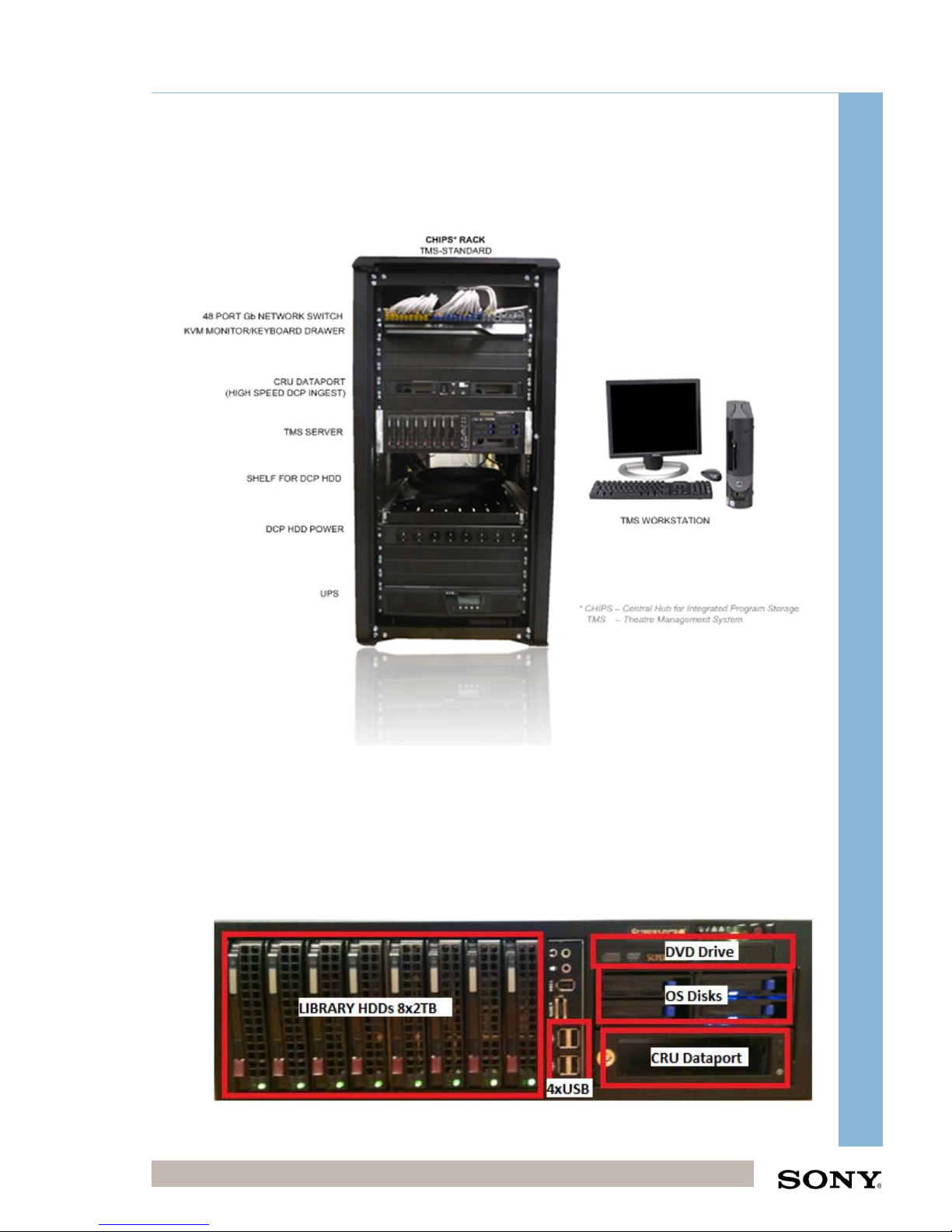
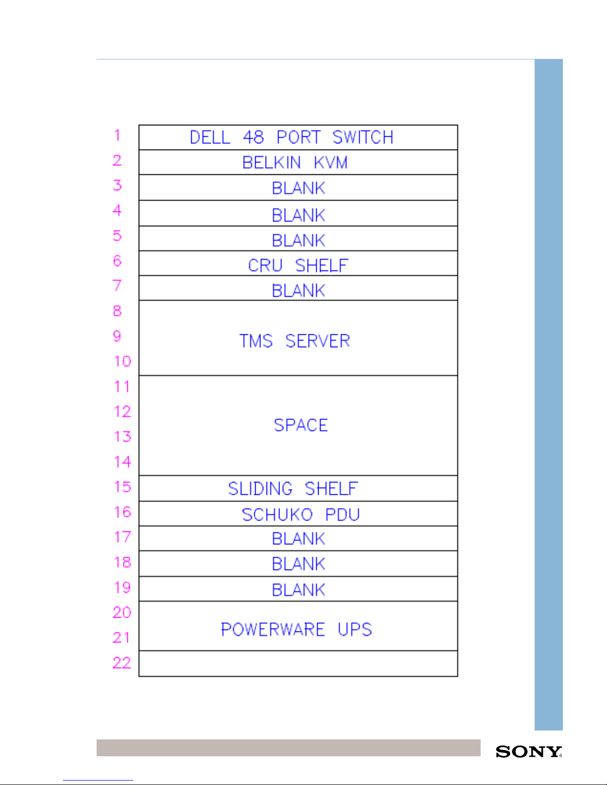
Populate the pre-wired CHIPS rack using the following schematics.
1.1 CHIPS Rack Layout Description
UPS - Uninterruptable Power Supply that will power the CHIPS system in the event of
a power cut. The UPS will do a clean shutdown of the system when the battery level
goes below a determined level.
TMS SERVER - The TMS server is where the Theatre Management System (TMS)
software is installed. All ingests of DCPs go through the TMS server either through
USB, eSATA or network interfaces. The CineWatch application is also installed which
provides a system monitoring service over SNMP. It also provides an increased level
of support as Sony can monitor and access the system remotely (if VPN link is
available). Upgrades of the projector firmware/software can be done remotely using
CineWatch
Page 6
Integrator Training, UK
Confidential Digital Cinema Deployment 6 of 49
October 15
CHIPS Stand-Alone Integrator Installation Training (CHIPS)
LIBRARY STORAGE - This is included in on board the TMS Server. The Library
Storage contains 8 x 2TB disks formatted to NTFS in a raid 6 configuration leaving
12TB useable space on the disk. Assuming a DCP feature size of 250GB this will
give storage for approximately 60 feature films (200GB DCP).
DCP HDD POWER AND USB DISTRIBUTION - A mains distribution panel is
provided so that a DCP HDD can be powered at the front of the rack. 4x USB ports
are available on the front of the TMS Application Server. Also KDM’s can be ingested
by USB memory stick.
CRU DATAPORT (High Speed Ingest) - The CRU Dataport provides increased
ingest speed through an eSATA interface to the Application Server. 2 x CRU DCP
HDD can be inserted, powered automatically and then ingested using the TMS Client.
KVM MONITOR/KEYBOARD DRAWER - The KVM monitor and keyboard is used for
configuration and maintenance of the system and can access both the Application
Server and the CineWatch Server. The KVM monitor is usually kept closed and not
used for daily use.
48 PORT Gb NETWORK SWITCH - The Gigabit switch is configured with a 4 x 1Gb
trunk to the Application Server for throughput and a single Gb link to each projector,
TMS Client and customer network.
TMS WORKSTATION - The TMS client PC is a standard PC which is not required to
be high performance. From this PC the TMS graphical user interface is accessed
through Windows Internet Explorer (or FireFox). The TMS Client is usually located in
the projection box and is the main point of interaction with the system. Scheduling,
Content Management, Status Monitoring and Show Management can be performed
at this terminal. A system can have multiple TMS Clients.
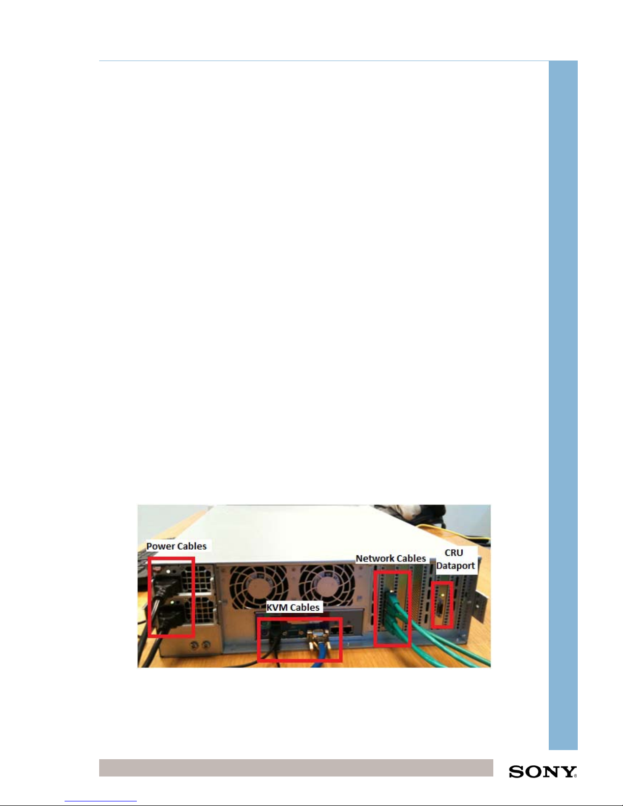
1.1.1 Rear connections of TMS Server
Figure 1 - Rear connections of TMS Server
Please note that the 4 network cables that form the 4Gb TMS trunk to the network
switch are all connected to the Network PCI card not the on board nics.
Page 7
Integrator Training, UK
Confidential Digital Cinema Deployment 7 of 49
October 15
CHIPS Stand-Alone Integrator Installation Training (CHIPS)
1.2 Rack Layout Schematic
Page 8

Integrator Training, UK
Confidential Digital Cinema Deployment 8 of 49
October 15
CHIPS Stand-Alone Integrator Installation Training (CHIPS)
1.3 Network Schematic
Page 9
Integrator Training, UK
Confidential Digital Cinema Deployment 9 of 49
October 15
CHIPS Stand-Alone Integrator Installation Training (CHIPS)
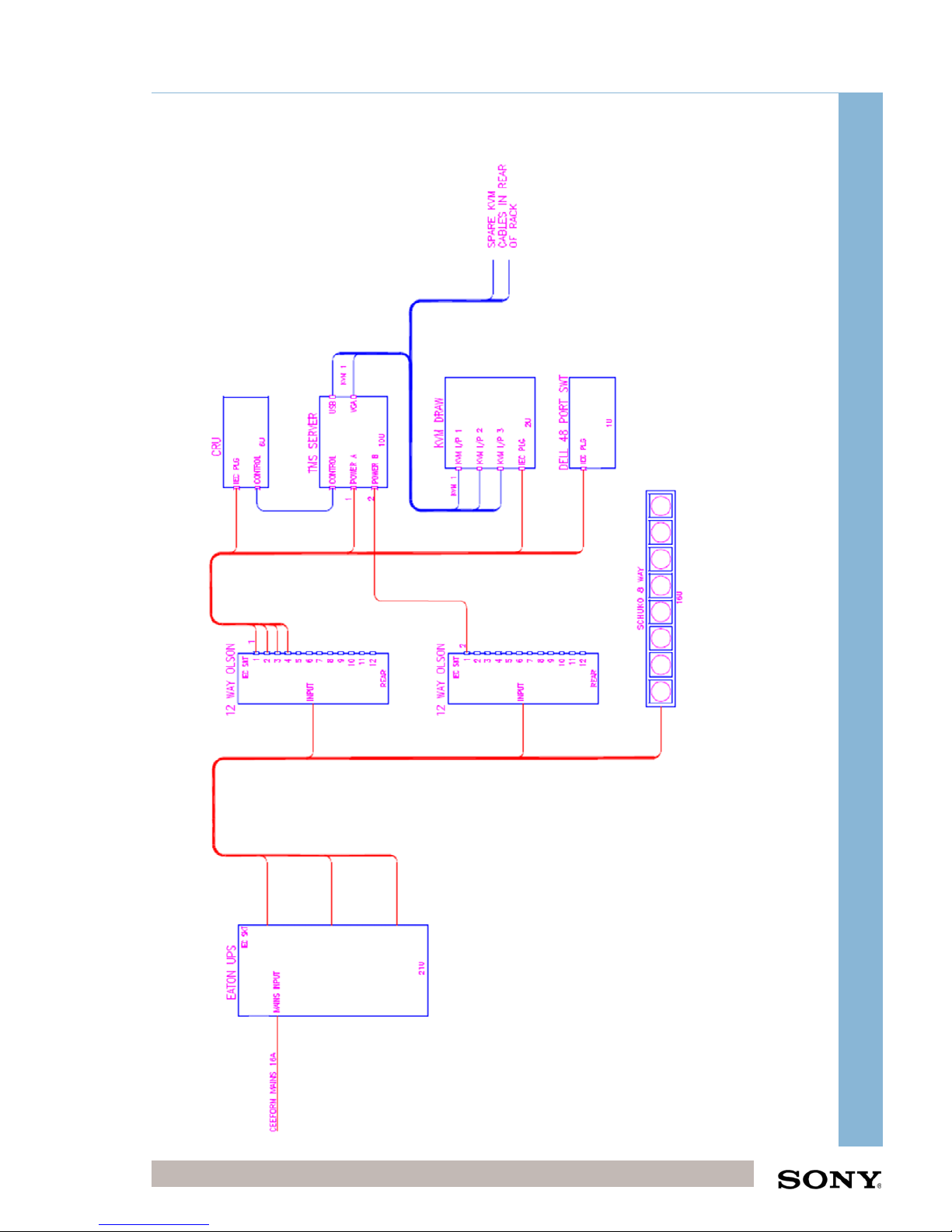
1.4 Power and Control Schematic
Page 10
Integrator Training, UK
Confidential Digital Cinema Deployment 10 of 49
October 15
CHIPS Stand-Alone Integrator Installation Training (CHIPS)
2 CHIPS Power Up Procedure
Before performing the power up procedure please confirm that all wiring is cabled as
per the network and control schematics
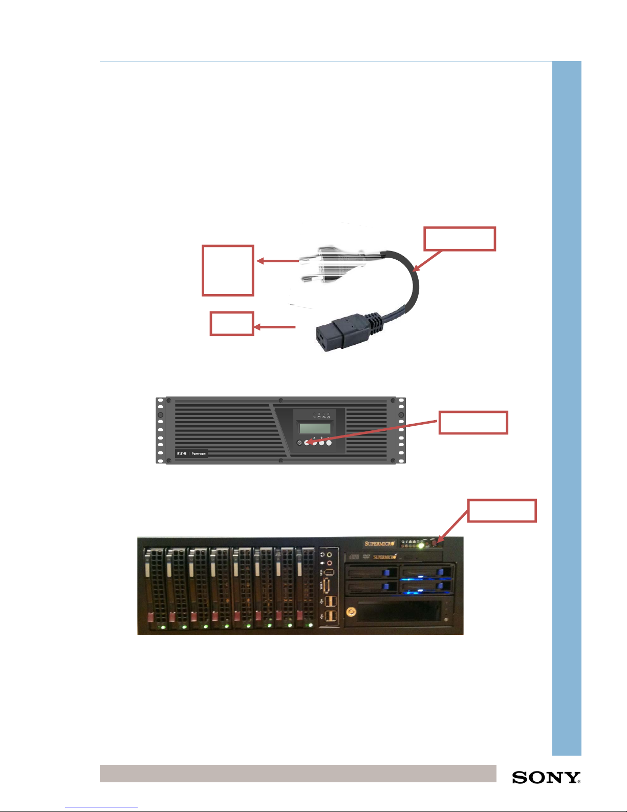
Connect power cable from the UPS to the mains power supply
The UPS cable has two connectors, a C19 16A rectangle connector that connects to
the UPS, and a European plug adapter that connects to the house power supply.
Since the rack only has two servers the standard house power supply will be
sufficient to power the equipment.
Turn on the UPS
Hold the ‘ON’ button on the UPS for 3 seconds to protect the load
Turn on the Supermicro TMS Server
Press the power switch on the front of the server.
UPS Cable
esc
ON Button
FRONT
UPS
House
Power
Supply
ON Button
Page 11
Integrator Training, UK
Confidential Digital Cinema Deployment 11 of 49
October 15
CHIPS Stand-Alone Integrator Installation Training (CHIPS)
2.1 IPMI Settings
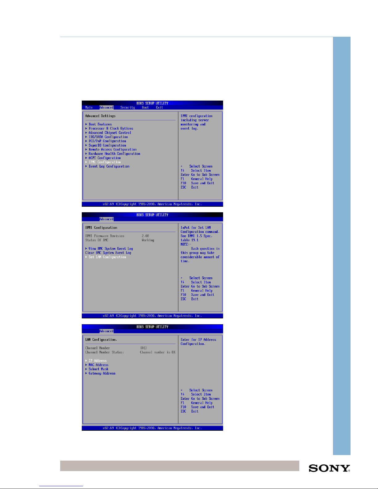
Make sure IPMI network cable is connected prior powering on the Server
Press “DEL” to enter the BIOS SETUP.
In this menu, Navigate to Advanced and IPMI
Page 12
Integrator Training, UK
Confidential Digital Cinema Deployment 12 of 49
October 15
CHIPS Stand-Alone Integrator Installation Training (CHIPS)
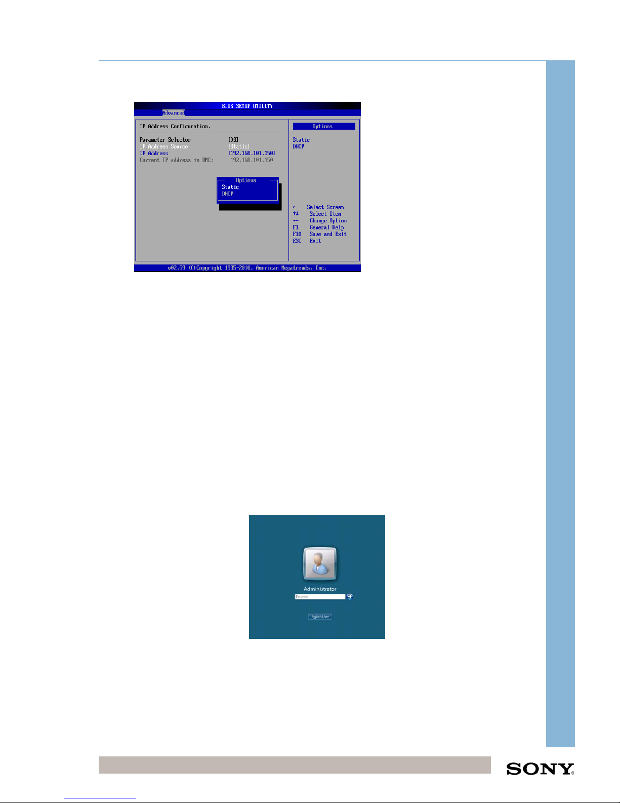
Use the IP schema for IPMI LAN IP address details
Enter the Subnet MASK as 255.255.255.0
Enter the Gateway as the Site Gateway in the IP Schema (10.XX.13.4)
Save and exit
Server will restart
Log on the TMS Server
Please see Usernames and Passwords section
Page 13
Integrator Training, UK
Confidential Digital Cinema Deployment 13 of 49
October 15
CHIPS Stand-Alone Integrator Installation Training (CHIPS)
3 CHIPS Power Down Procedure
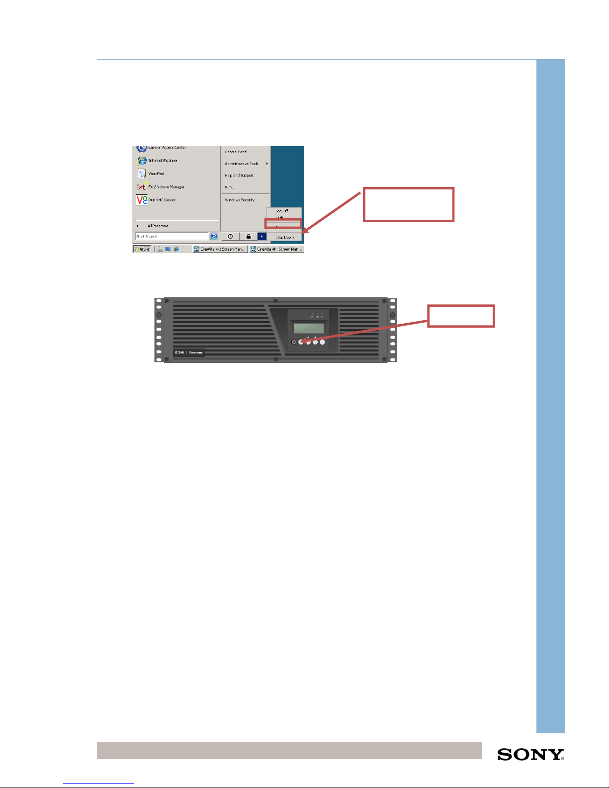
Shutdown the TMS Server using the OS
Using the KVM Drawer shut down the TMS Server.
Turn off the UPS
Hold the ‘ON’ button on the UPS for 3 seconds to unprotect the load
Disconnect the power cables from the mains supply
Remove the UPS power cable from the wall socket (if required).
Press
Shutdown
esc
ON Button
FRONT
Page 14
Integrator Training, UK
Confidential Digital Cinema Deployment 14 of 49
October 15
CHIPS Stand-Alone Integrator Installation Training (CHIPS)
4 Usernames and Passwords
The following usernames and passwords are the typical ones implemented in a
CHIPS rack build. Please confirm on a project by project basis.
CHIPS Server Windows Login Credentials
USERNAME PASSWORD NOTES USED BY
Administrator S0nytms01 Administrator Rights Sony/Dealer/Exhibitor
TMS Software Login Credentials
USERNAME PASSWORD NOTES USED BY
tmsadmin cinemasystem
Administrator Rights
(Changed in v1.63.1)
Sony/Dealer
CineWatch Software (Device Monitor) Login Credentials
USERNAME PASSWORD NOTES USED BY
admin admin Administrator Rights Sony/Dealer
TMS Client Workstation Windows Login Credentials
USERNAME PASSWORD NOTES USED BY
Administrator S0nytms01 Administrator Rights Sony
tmsuser Password01 Standard User Rights
Sony and
Customer
Page 15
Integrator Training, UK
Confidential Digital Cinema Deployment 15 of 49
October 15
CHIPS Stand-Alone Integrator Installation Training (CHIPS)
5 Standard IP Address Schema
Please see the document, Local IP Schema supplied with this Integrator Installation
Training manual.
CHIPS System IP Addresses Default
Network Interface
192.168.101.0/24
CHIPS Switch Management
192.168.101.1
Default Gateway
192.168.101.254
TMS Server
192.168.101.5
TMS Client PC
192.168.101.8
UPS
192.168.101.9
Satellite Receiver (Optional)
192.168.101.10
Projector TMS 1 (Ctrl IN Port)
192.168.101.11
Projector TMS 2 (Ctrl IN Port)
192.168.101.12
Projector TMS 3 (Ctrl IN Port)
192.168.101.13
Projector TMS 4 (Ctrl IN Port)
192.168.101.14
Projector TMS 5 (Ctrl IN Port)
192.168.101.15
Projector TMS 6 (Ctrl IN Port)
192.168.101.16
Projector TMS 7 (Ctrl IN Port)
192.168.101.17
Projector TMS 8 (Ctrl IN Port)
192.168.101.18
Projector TMS 9 (Ctrl IN Port)
192.168.101.19
Projector TMS 10 (Ctrl IN Port)
192.168.101.20
Projector S2S 1 (Data IN Port)
192.168.101.51
Projector S2S 2 (Data IN Port)
192.168.101.52
Projector S2S 3 (Data IN Port)
192.168.101.53
Projector S2S 4 (Data IN Port)
192.168.101.54
Projector S2S 5 (Data IN Port)
192.168.101.55
Projector S2S 6 (Data IN Port)
192.168.101.56
Projector S2S 7 (Data IN Port)
192.168.101.57
Projector S2S 8 (Data IN Port)
192.168.101.58
Projector S2S 9 (Data IN Port)
192.168.101.59
Projector S2S 10 (Data IN Port)
192.168.101.60
TMS IMPI PORT
192.168.101.222
Page 16
Integrator Training, UK
Confidential Digital Cinema Deployment 16 of 49
October 15
CHIPS Stand-Alone Integrator Installation Training (CHIPS)
6 CHIPS Initial Configuration
The CHIPS system needs to be configured before you proceed. The TMS server has
a standard Sony TMS image on it which covers the core software installation however
there a number of tasks that need to be completed to make the system operational.
Please make sure all cabling is completed before following the next steps.
6.1 TMS Server Configuration
6.1.1 Basic OS Options
When the TMS server is powered on for the first time you will be greeted with the
standard Windows options for configuring the Operating system.
Enter Region Select your local region
Enter time/currency Select your local time/currency
Keyboard Select UK
The Keyboard should be selected as UK because the KVM keyboard is UK. The
keyboard setting for your region can be selected once in Windows.
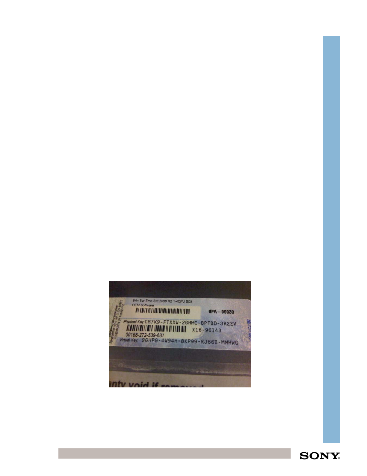
6.1.2 Windows Activation
Windows will ask for the activation key for TMS Server. Please use the telephone
option during activation to obtain the License key as the internet will not be connected
during the installation.
Enter the Virtual Key (Bottom Key) and then select Telephone system
Product key format: AAAAA-BBBBB-CCCCC-DDDDD-EEEEEE
Page 17
Integrator Training, UK
Confidential Digital Cinema Deployment 17 of 49
October 15
CHIPS Stand-Alone Integrator Installation Training (CHIPS)
6.1.3 Administrator Account Password
Once the server has restarted there should be the following users available.
Administrator - Administrator and Support Account
DCP Delivery - FTP account used for DCP Delivery
POSUSER - Point of Sale User (May not be required)
PRESHOW - Preshow User (May not be required)
Click on Administrator and when prompted for a password enter the following
password:
Administrator PW:
S0nytms01
This password must be used otherwise the TMS service that provides the TMS GUI
will not start!
Number 0
Page 18
Integrator Training, UK
Confidential Digital Cinema Deployment 18 of 49
October 15
CHIPS Stand-Alone Integrator Installation Training (CHIPS)
6.1.4 TMS Server Network Settings
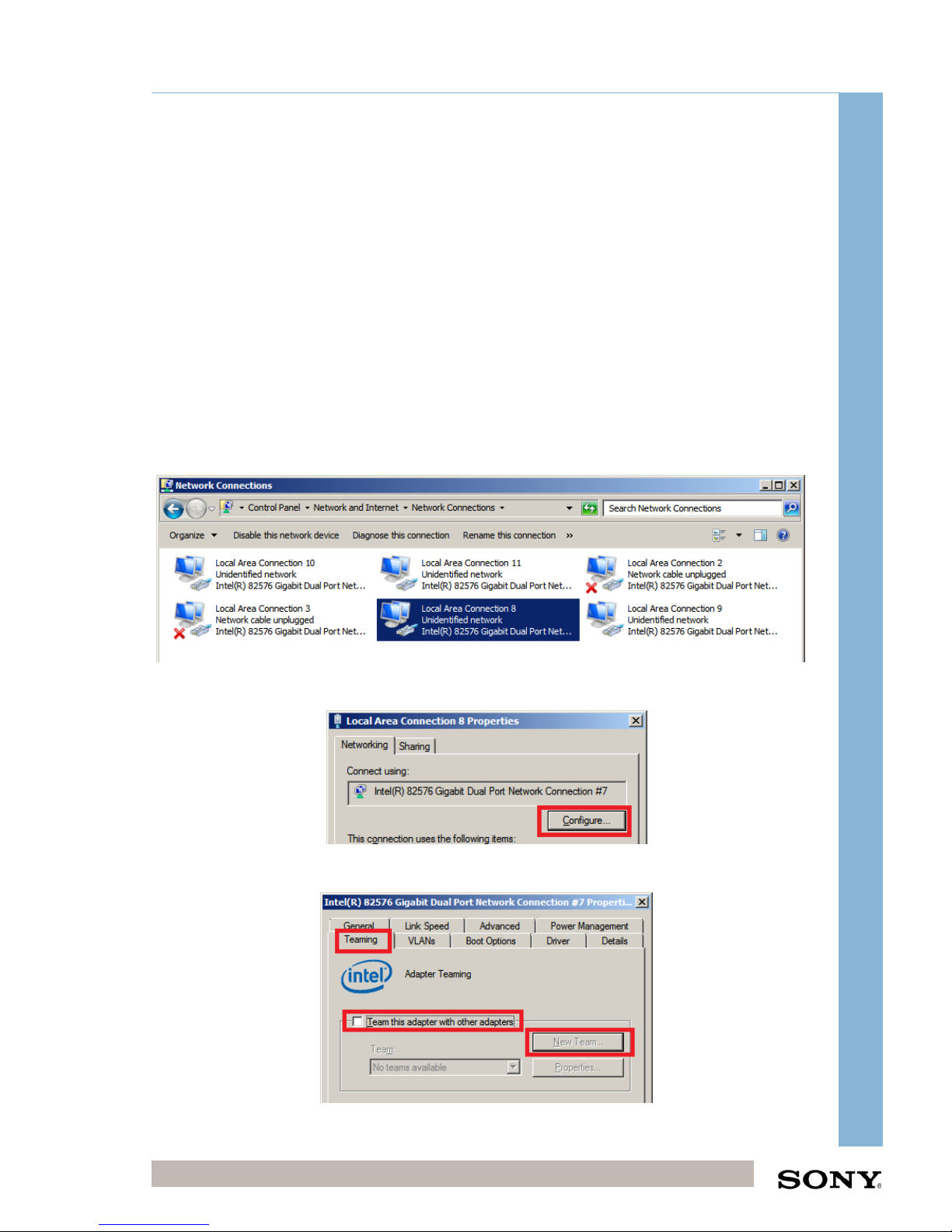
The next steps show how to configure the four network ports to form and TMS team.
Remove the current network settings on the onboard NICs
Go to Start Menu > Control Panel > Network and Sharing Centre
Click on Change Adapter Settings to see the NICs on the TMS server
Right Click on Local Area Connection 7 > Properties
Click on Configure > Settings
Remove Team
Yes, Ok
To configure the TMS Network Team
Right Click on Local Area Connection 8 > Properties
Click on Configure > Teaming Tab
Click on “Team this adapter...” then click on “New Team”
Page 19
Integrator Training, UK
Confidential Digital Cinema Deployment 19 of 49
October 15
CHIPS Stand-Alone Integrator Installation Training (CHIPS)
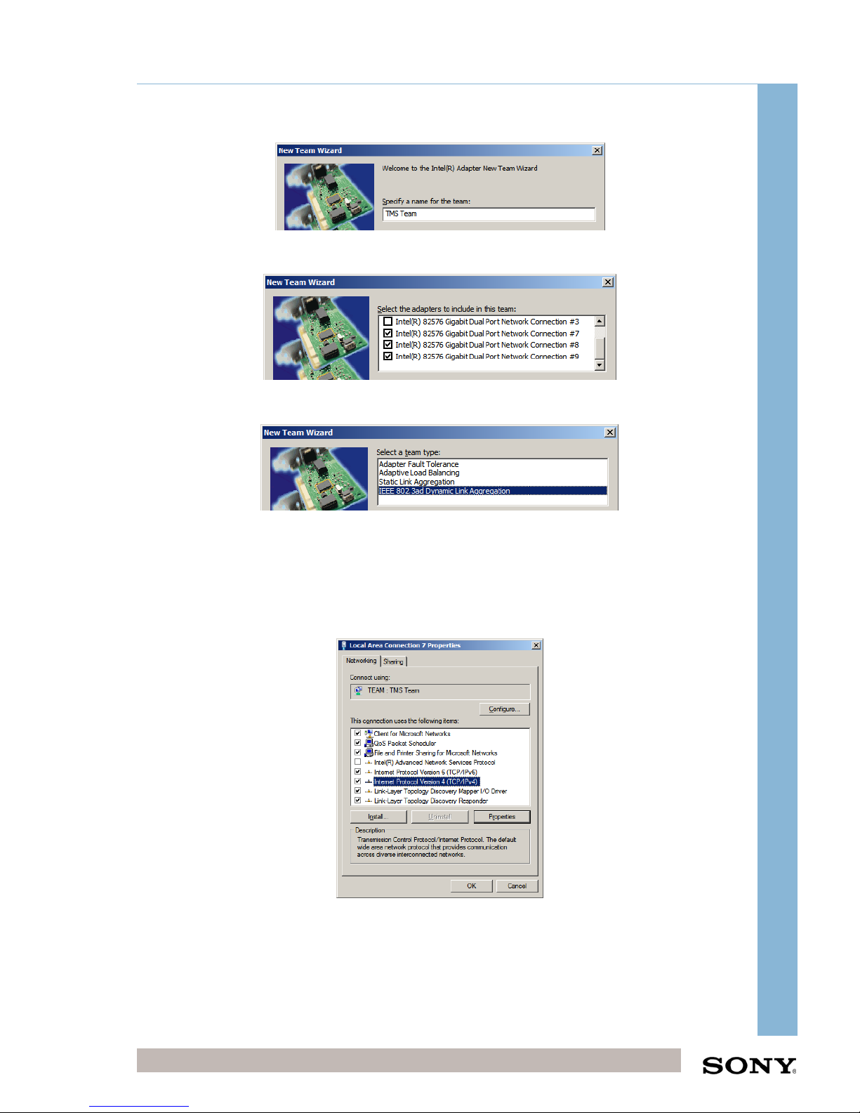
Name the team: TMS Team
Click Next, then Select Network Connections 7, 8, 9, 10
Click Next, then Select IEEE 802.3ad Dynamic Link Aggregation
Click Next, Finish, Ok.
Configure the TMS Team IP Address
On the Adapter Settings page select Local Area Connection 7 (TMS Team)
Right Click > Properties > Select Internet Protocol Version 4 > Properties
Page 20
Integrator Training, UK
Confidential Digital Cinema Deployment 20 of 49
October 15
CHIPS Stand-Alone Integrator Installation Training (CHIPS)
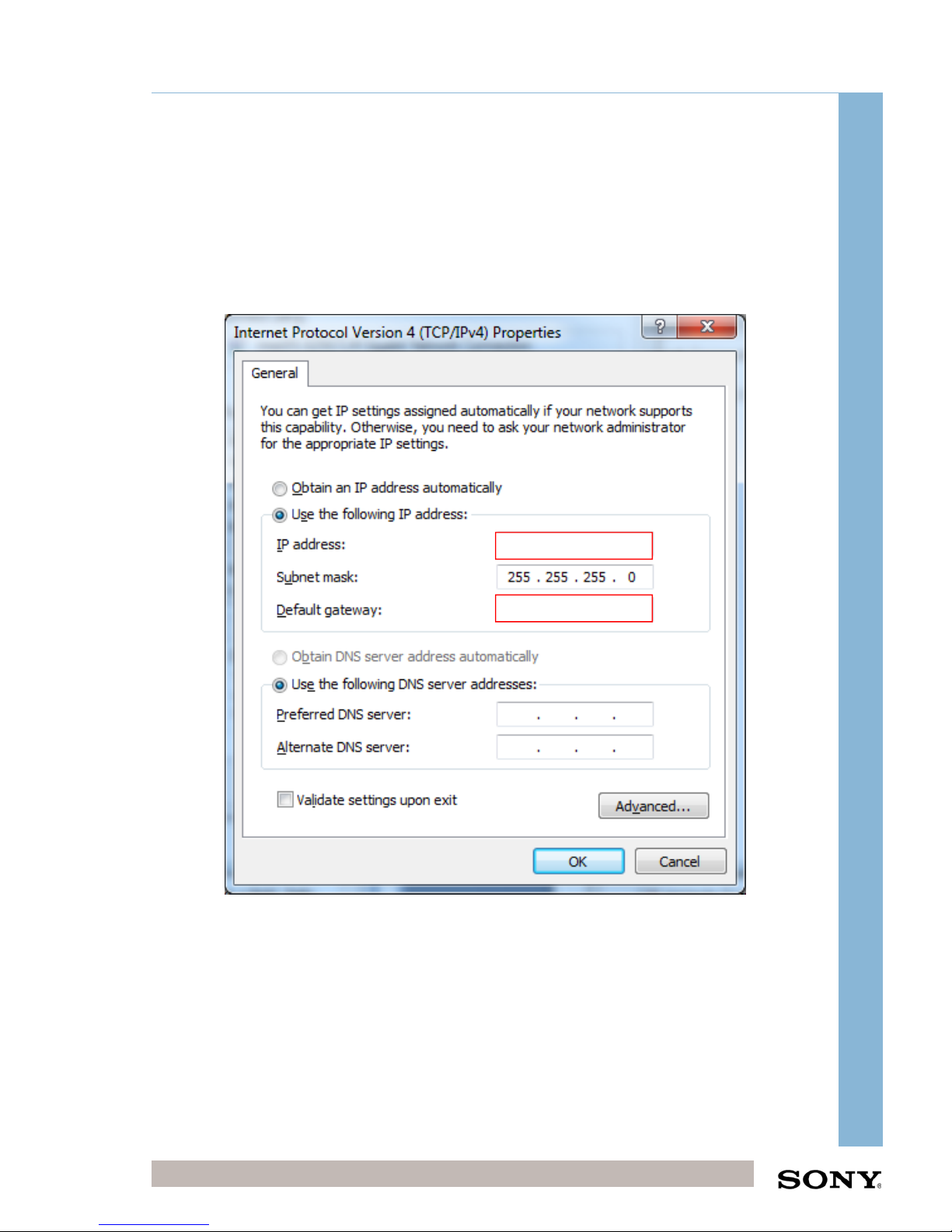
Use the following IP information from the Local IP Schema document
supplied:
o IP Address (CHIPS TMS Server IP) – 192.168.101.5
o (Subnet Mask) 255.255.255.0
o Default Gateway (SITE Gateway IP) – 192.168.101.254
Where XX = Site Code/IP
TMS Network Configuration Complete
10.XX.13.202
10.XX.13.4
Page 21
Integrator Training, UK
Confidential Digital Cinema Deployment 21 of 49
October 15
CHIPS Stand-Alone Integrator Installation Training (CHIPS)
6.2 Switch Configuration
The switch provided with the TMS is not configured.
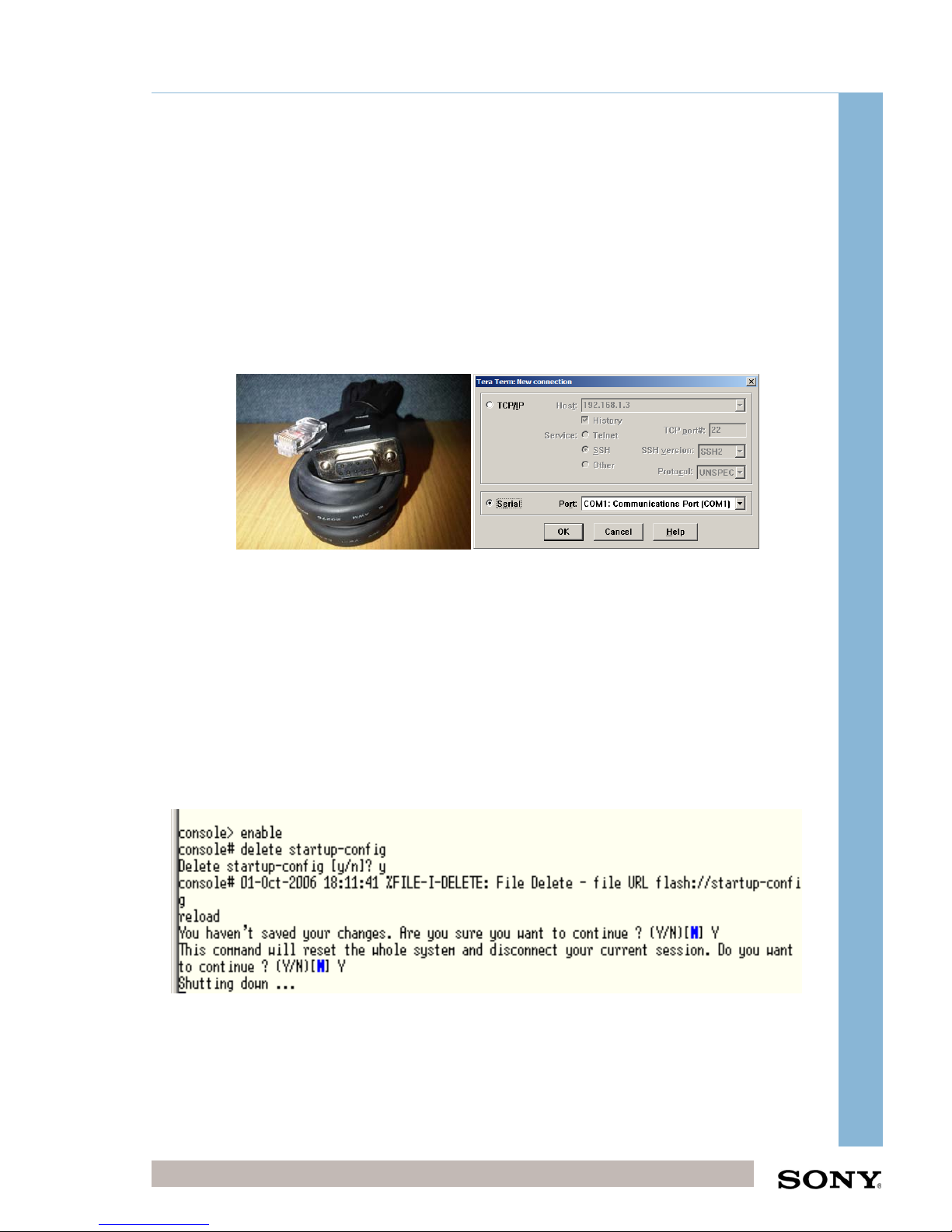
To configure the Switch IP Address
Using a Serial to Ethernet cable (provided with Switch) connect the TMS serial
port (9-pin D-sub Green male port in the back of the TMS server) to the switch
configuration Ethernet port (the Ethernet port named 10101 on the front right
of the switch).
On TMS Server go to Start Menu > All Programs > Teraterm
Select Serial Port COM1
When the TeraTerm window appears press enter and “console>” should
appear
Enter the following commands:
o Enable (To enable advanced commands)
o Delete startup-config
o Y (to confirm the deletion)
o Reload (to restart the switch)
o Y (to confirm restart)
The switch will now restart, during the restart sequence the Easy Startup
sequence will appear press Y to enter
Page 22

Integrator Training, UK
Confidential Digital Cinema Deployment 22 of 49
October 15
CHIPS Stand-Alone Integrator Installation Training (CHIPS)
If a predefined IP
Schema is not available, enter the following Details;
o Enter SNMP Community String public
o Enter IP Address of Management System 10.XX.13.202
o Enter Username Leave Default
o Enter Password Leave Default
o Are you sure Y
o IP Address of Device 192.168.101.1
o Subnet Mask 255.255.255.0
o Gateway Address 192.168.101.254
o Confirm that all is correct Y
o Exit (make sure you type this so that the switch is logged out)
Page 23

Integrator Training, UK
Confidential Digital Cinema Deployment 23 of 49
October 15
CHIPS Stand-Alone Integrator Installation Training (CHIPS)
Close TeraTerm and remove cable
Create Link Aggregation on Switch (make 4 ports look like 1 port)
Open Internet Explorer On TMS Server
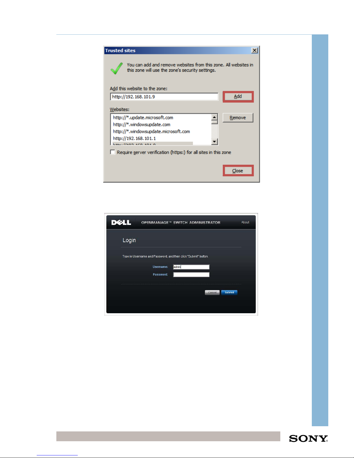
Go to Switch address: http://192.168.101.1
Add to trusted sites if GUI is not displayed correctly;
o In IE, go to Tools > Internet Options > Security Tab
o Click Trusted sites > Sites Button
Page 24
Integrator Training, UK
Confidential Digital Cinema Deployment 24 of 49
October 15
CHIPS Stand-Alone Integrator Installation Training (CHIPS)
o Add the site address and then click close and apply
o Restart internet explorer and navigate to same page
Enter UN: admin PW: (No Password)
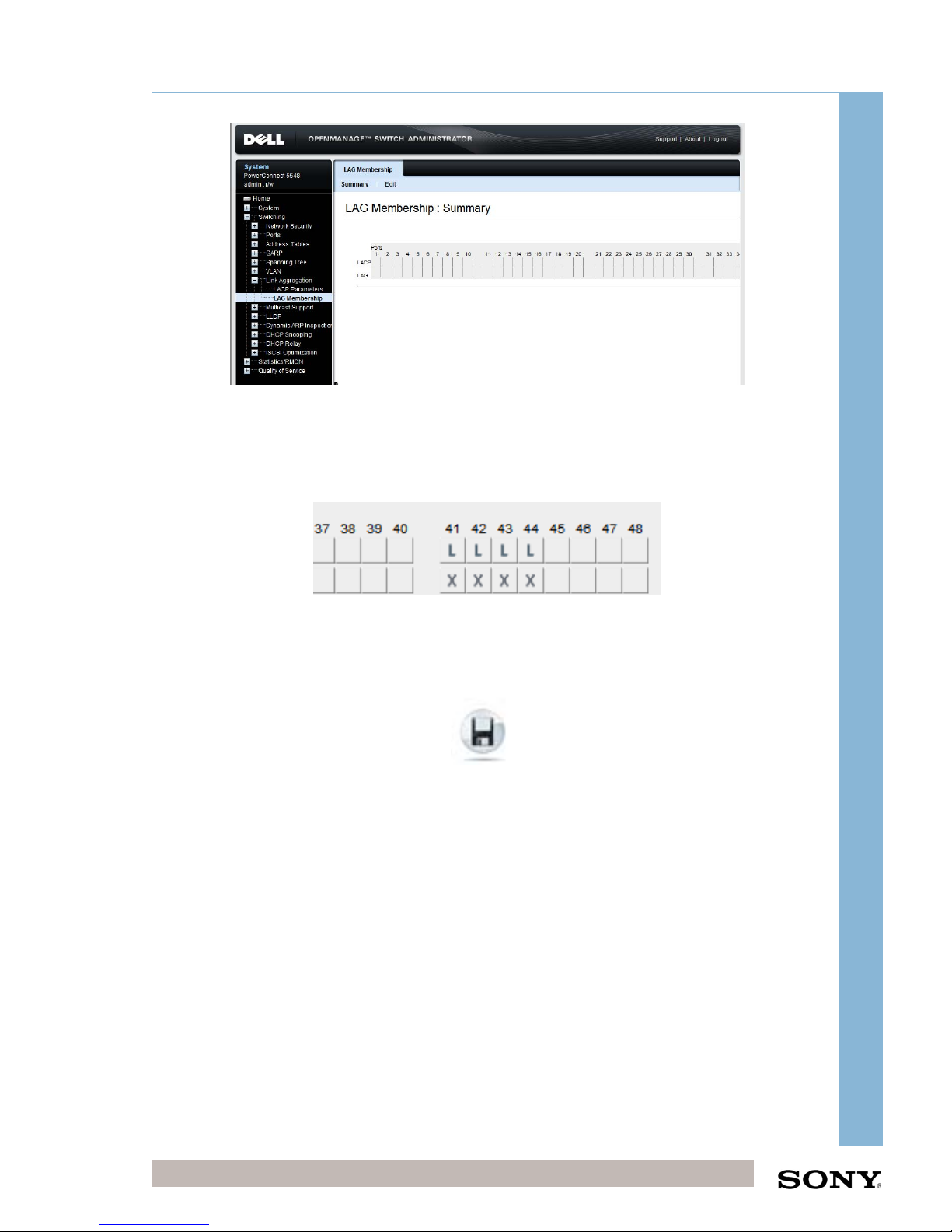
Go to switching > Link Aggregation > LAG Membership
Page 25
Integrator Training, UK
Confidential Digital Cinema Deployment 25 of 49
October 15
CHIPS Stand-Alone Integrator Installation Training (CHIPS)
Click Edit
Select LAG on ports 41, 42, 43, 44
Select LACP on ports 41, 42, 43, 44
Click Apply and wait 30seconds until success is shown on webpage
Click Save Button to save the switch configuration
Logout and close browser
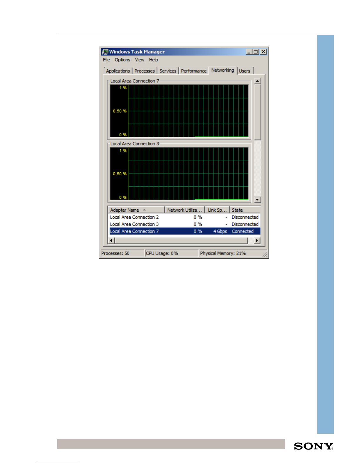
To Check Trunk is Working
On TMS Server, right click on the taskbar > Start Task Manager
Go to networking tab
Now the Local Area Connection 7 (TMS Team) link speed will be shown as
4Gb.
Page 26
Integrator Training, UK
Confidential Digital Cinema Deployment 26 of 49
October 15
CHIPS Stand-Alone Integrator Installation Training (CHIPS)
This team is resilient to individual cables being broken.
TMS Network Teaming complete
Page 27
Integrator Training, UK
Confidential Digital Cinema Deployment 27 of 49
October 15
CHIPS Stand-Alone Integrator Installation Training (CHIPS)
6.3 UPS Configuration
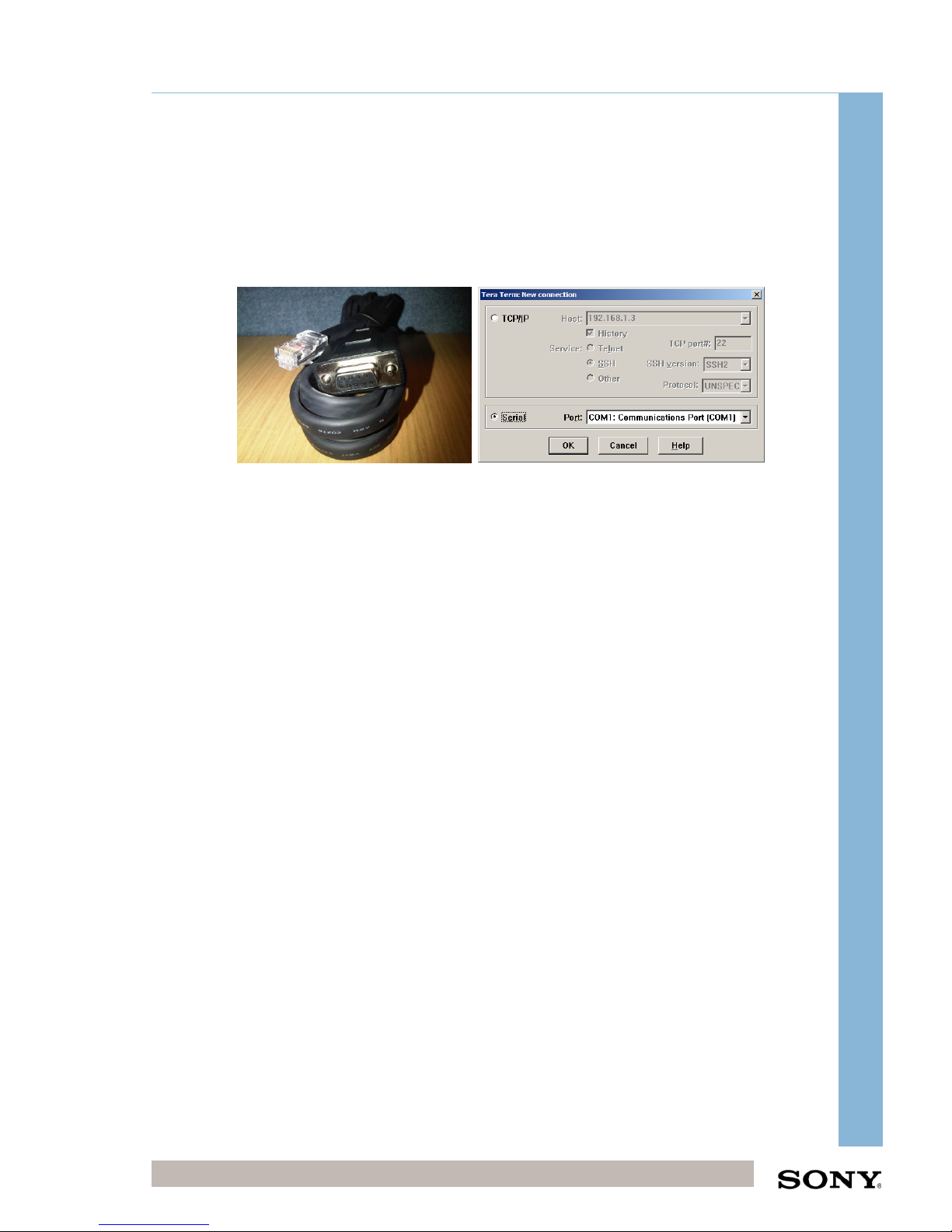
Connect the serial to Ethernet cable from the TMS Server Serial Port to the
UPS Configuration Ethernet Port.
Open TeraTerm
Select Serial Port COM1
Press “Enter”
Password: admin
Follow onscreen instructions and change UPS IP using the predefined IP
Schema.
Navigate to C:\CHIPS Utilities\Eaton Powerware Netwatch\Windows
Run the installer and select remove all installed components
Re-run the installer and install with default options
Choose Manual Discovery and enter the IP address of the UPS
Choose Default options and finish installation
Check PowerWare Netwatch Service is started
Page 28

Integrator Training, UK
Confidential Digital Cinema Deployment 28 of 49
October 15
CHIPS Stand-Alone Integrator Installation Training (CHIPS)
6.4 Setting up the Library
BIOS setting for RAID 6
1) Go to Server Manager -> Storage -> Disk Management, select GPT formatting
when it appears.
2) Right Click on first disk on storage -> New simple volume.
3) Select the 8x 2TB disks and add to the selected box.
4) Assign the drive a Letter D:\
5) Format to NTFS, Default Allocation Unit Size, Label: Library1 (select Quick
Format). Select “Yes” when prompted about OS not being able to start (this is
regards to formatting the OS drive).
6.5 TMS Licensing
The TMS will not be licensed.
To License the TMS
Sony will provide you with a TMS installation key. Contact Sony Account
manager with the TMS Team Mac Address.
o To obtain a mac address
o Run a command prompt window
o Type ipconfig/all
o Record the Physical (MAC) address listed next to the TMS Team
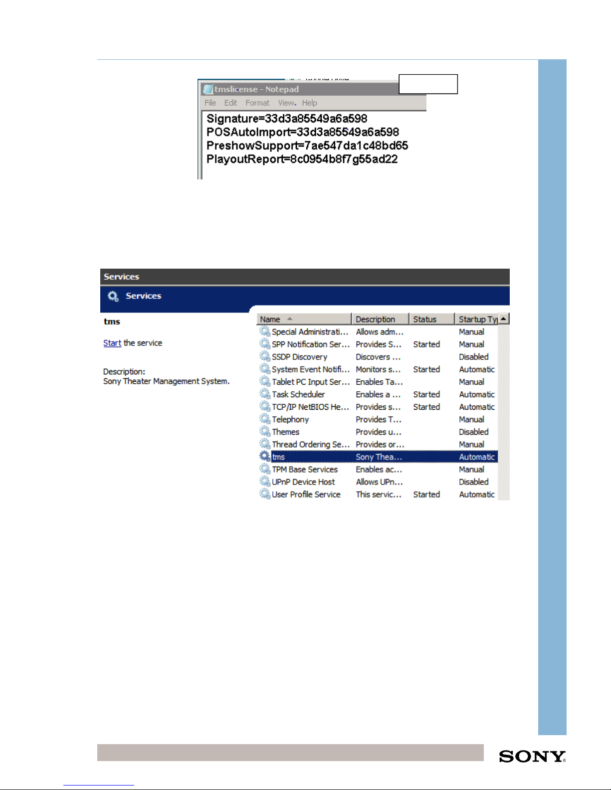
TMS Installation key is a 16 digit alphanumeric code
Go to C:\Program Files\Sony\TMS
Open tmslicense file using Notepad
Type the installation Key next to the “signature=”
Page 29
Integrator Training, UK
Confidential Digital Cinema Deployment 29 of 49
October 15
CHIPS Stand-Alone Integrator Installation Training (CHIPS)
o Preshow and Playout Report licenses are optional and purchased
separately.
Save and Close
Go to Start Menu Administrative Tools > Services > Start tms service
Example
Page 30
Integrator Training, UK
Confidential Digital Cinema Deployment 30 of 49
October 15
CHIPS Stand-Alone Integrator Installation Training (CHIPS)
7 TMS software configuration
7.1 Start/Restart TMS Service (if required)
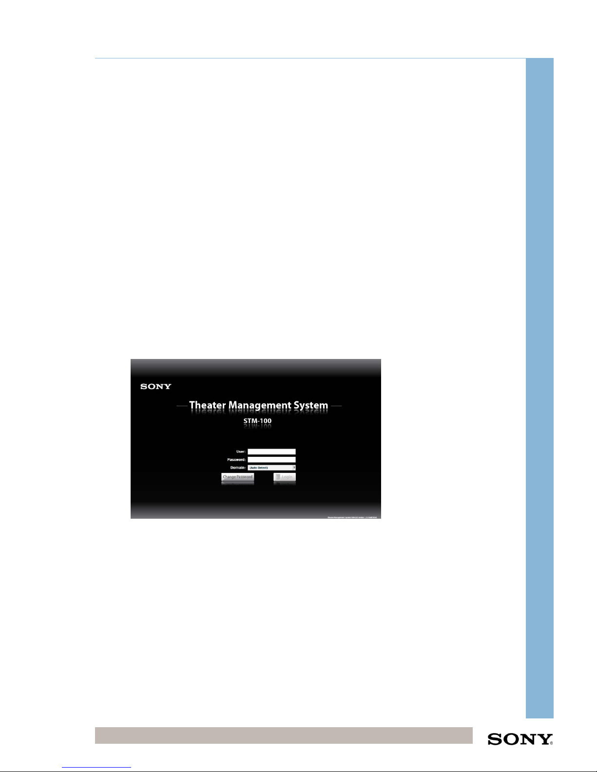
Start Menu > Administrative Tools > Services > tms (Start)
Note: every time the TMS configuration is changed it requires restarting the TMS
Service. To do so: Start Menu > Administrative Tools > Services > tms (Restart).
7.1.1 View TMS GUI on Web browser
On the desktop, the TMS Shortcut is predefined as
http://localhost:8400/TMS-Server
Double-click on the TMS Shortcut on the Desktop
Check that the log in page is visible
If the page does not show up, add it to the trusted list in Internet Explorer (see page
22 for how to do it)
7.2 Log in Details
Double click on the TMS icon on desktop
Login
UN: tmsadmin
PW: cinemasystem
The majority of the configuration of the software will already be completed during the
factory build of the projector. The sections below document the processes that need
to take place onsite once the CHIPS rack has been powered on and connected to a
projector.
Page 31
Integrator Training, UK
Confidential Digital Cinema Deployment 31 of 49
October 15
CHIPS Stand-Alone Integrator Installation Training (CHIPS)
7.3 Create an Auditorium
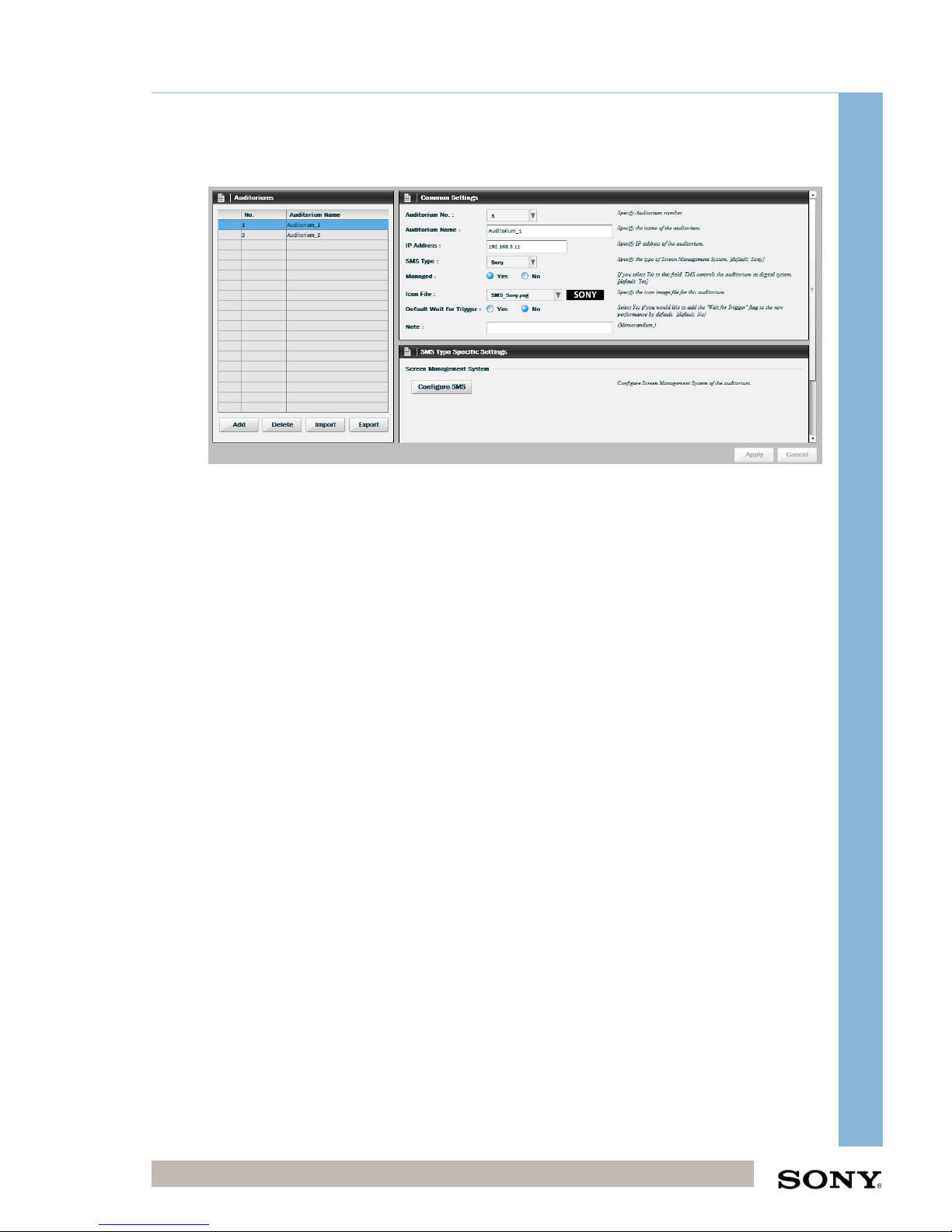
Click Configuration > Auditorium > Add
Enter the following details:
Auditorium Number
Auditorium Name (usually left as default)
Enter IP Address of projector (from IP Address schema for project)
Select SMS Type (Sony / Doremi / Dolby)
Select ‘yes’ if the projector is to be managed by the TMS
‘No’ can be selected to have the screen appear but not be managed
(such as a 35mm projector for example), to keep the numbering
consistent within the theatre.
Select the Icon file (Sony / Doremi / Dolby), this should reflect the Projector
Head.
In some cases a Doremi or Dolby can be used with a Sony projector
head and therefore this will be different from the SMS type.
Default Wait for Trigger set to No (default)
This can be set to ‘yes’ if the projector is cued by an external GPI trigger
such as a 35mm performance.
Click apply and repeat for remaining screens
7.3.1 Specific Settings for Doremi Servers
Please use the “manager” username and password “password” for the account
information when creating the Doremi Auditorium. If the root or admin user is used
only limited TMS functionality is achieved.
Page 32
Integrator Training, UK
Confidential Digital Cinema Deployment 32 of 49
October 15
CHIPS Stand-Alone Integrator Installation Training (CHIPS)
7.4 Edit Cue Template Settings
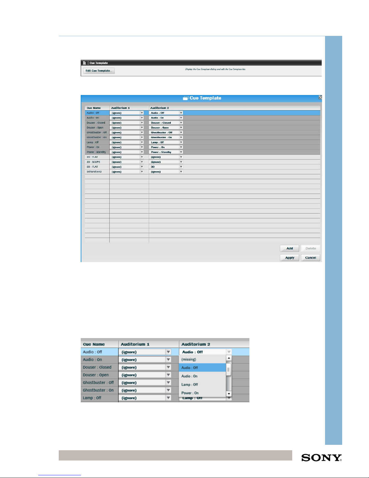
Go to Configuration > SPL/Pack > Edit Cue Template
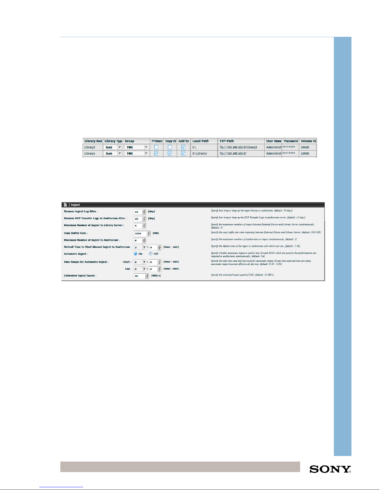
The above screen will be displayed showing the default Cues for the created
auditoriums. The cues in dark grey are default Projector cues that need to be selected
for each projector created. The default value is ‘ignore’, if this remains when the cue
is inserted on an SPL created in the TMS when this SPL is sent to that projected the
ignored cue will be removed thus ignoring it.
Use the drop down box to select the relevant such as in Auditorium 2 shown in the
screen above.
The available cues on the projector will be automatically be pulled through to the
TMS, if these are not visible please confirm the projector is powered on with the
Page 33
Integrator Training, UK
Confidential Digital Cinema Deployment 33 of 49
October 15
CHIPS Stand-Alone Integrator Installation Training (CHIPS)
correct network cables in place. If cues are not visible, delete the auditorium from
TMS, restart postgresql service, add auditorium restart postgresql service.
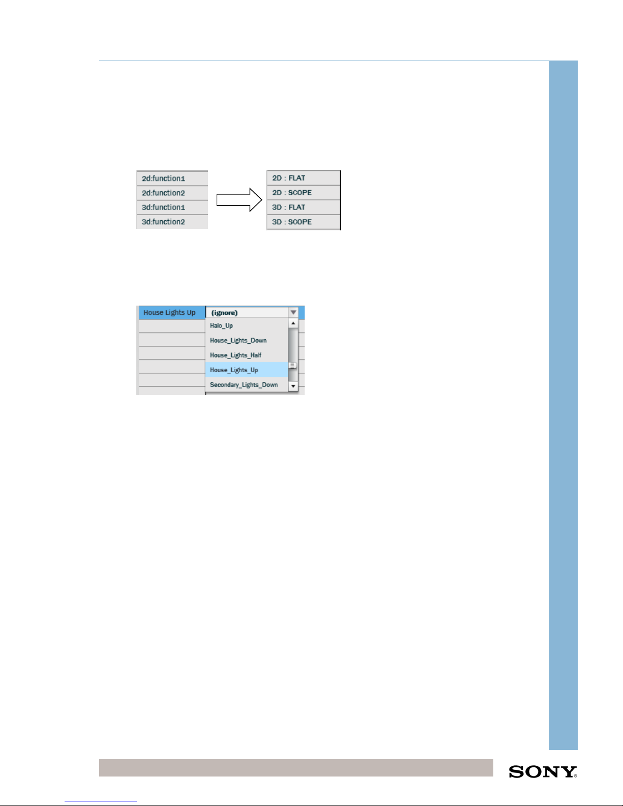
Changing the Lens Function Cue Names
When the TMS is first installed the Lens functions are shown below. Please change to
the corresponding values.
Adding Additional Cues
It is possible to add as many cues as required to the Edit Cue Template. Click on the
‘add’ button to add an additional cue. Double click on the cue name to change it and
click on the drop down box to assign the relevant projector cue to the new cue.
Please also add the following cues before adding house automation cues:
2D : DVI FLAT
2D : DVI SCOPE
3D : DVI FLAT
3D : DVI SCOPE
Also add cues for HDMI board if required:
2D : HDMI FLAT
2D : HDMI SCOPE
3D : HDMI FLAT
3D : HDMI SCOPE
These are for alternative content. The cues will be automatically shown in the TMS if
the function has been setup the projector.
Page 34
Integrator Training, UK
Confidential Digital Cinema Deployment 34 of 49
October 15
CHIPS Stand-Alone Integrator Installation Training (CHIPS)
8 Other Useful TMS Settings
These other settings are useful to know but should already be completed during the
factory build.
8.1 Configuration – Library Settings
Configuration -> Library
NB. After each change in configuration has been applied the TMS service will
need to be restarted.
Add Libraries into TMS
8.1.1 Ingest Settings
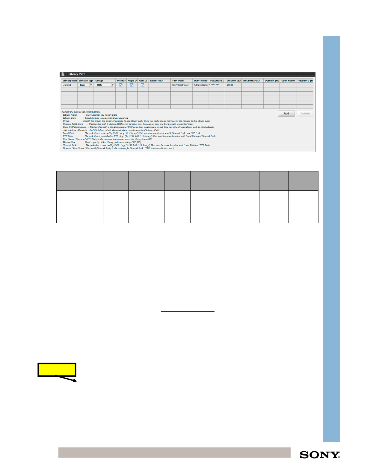
Please set the following in ‘Ingest’ Settings
Most of the settings should be kept default, change the following:
Maximum Number of Ingest to Library Server: 4
This is to make sure that when 4 DCP HDD are in the CRU they are all being
ingested simultaneously.
Maximum Number of Ingest to Auditorium: 8
Page 35
Integrator Training, UK
Confidential Digital Cinema Deployment 35 of 49
October 15
CHIPS Stand-Alone Integrator Installation Training (CHIPS)
8.1.2 Library Path
Please set the following Library Path Settings
Library
Name
Library
Type
Primary
KDM
Local Path
FTP
Settings
Network Path Domain Username Password
Library
1
Both Tick leave blank
FTP
settings
IP, UN
and PW.
leave blank leave blank
leave
blank
leave
blank
Click ‘Add’ to add each library.
The local path of the library is path as seen from the TMS Server. If the storage was
directly attached to the server it would be seen as a drive letter.
Local Path Example: D:\Library1
The FTP settings are very important and are sent to the projector when using the FTP
protocol to send data. FTP is also used to interrogate the projectors content and show
on the TMS library.
FTP Path Example: ftp://192.168.101.5/
UN: Administrator
PW: FTP Administrator Password (same as Server Administrator password)
The Network Path of the library is the path as seen from the SMS server. This will be
as a network share as the example below.
Volume Size: Enter the volume size of the Library folder in GB, typically 11170GB.
Network Path: Leave blank (so that FTP protocol is used)
Click Apply and restart the service.
Important
Page 36
Integrator Training, UK
Confidential Digital Cinema Deployment 36 of 49
October 15
CHIPS Stand-Alone Integrator Installation Training (CHIPS)
8.1.3 External Device Path
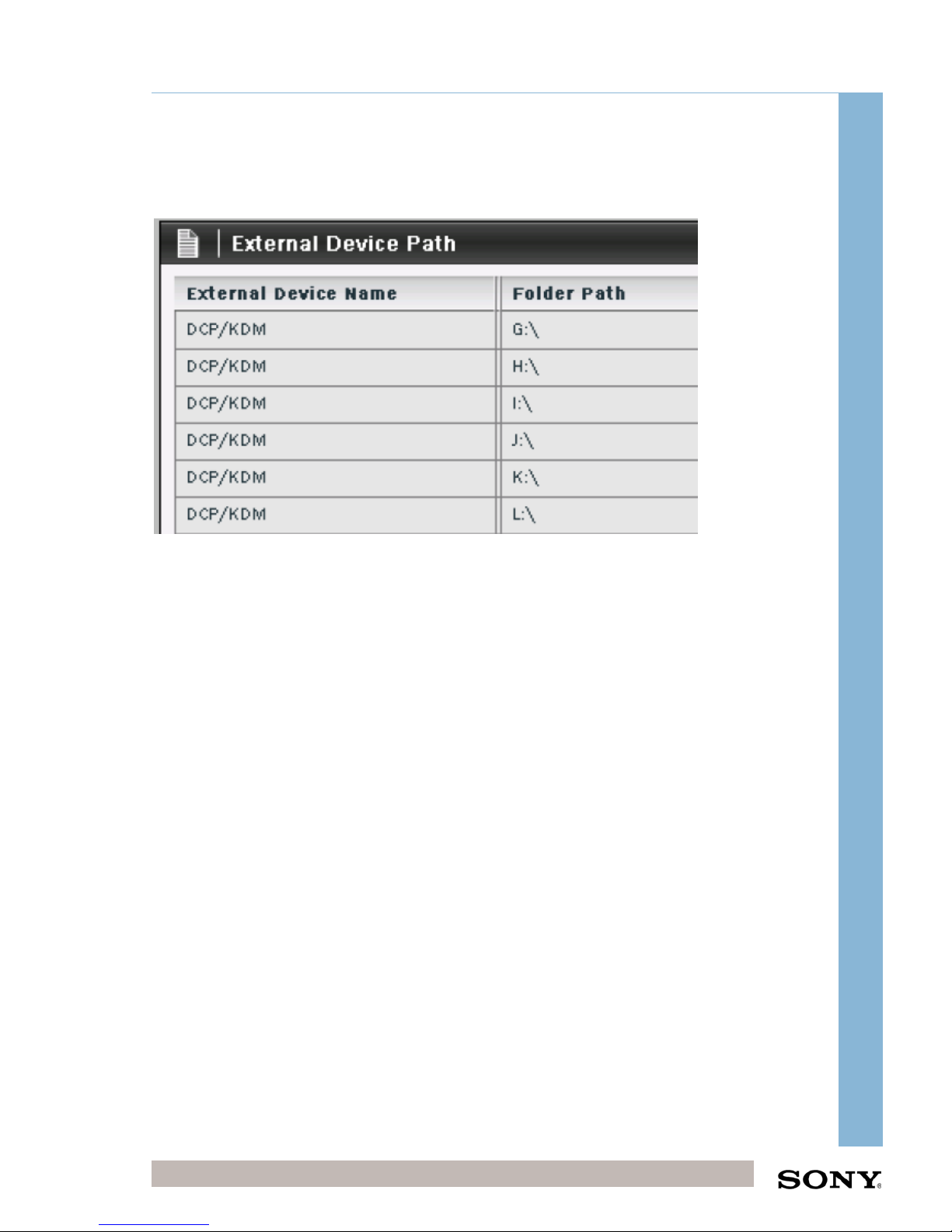
The settings below will be set as standard as part of your TMS System.
Click ‘Add’ to add each external device line.
Click Apply and restart the TMS Service
You can also add FTP external device paths from which content can be copied to the
TMS. A common example of this use is pulling DCP content from Satellite Receivers.
8.2 Configuration - SPL/Pack Settings
8.2.1 Add Additional Pack Types
Click Configuration -> SPL/Pack -> Pack Type
Click add then change the name, displayed length and colour to the desired values.
8.3 Configuration - Schedule Settings
8.3.1 Schedule Import
Make sure this is set to the correct POS File Type. The default is the Sony file type.
Page 37
Integrator Training, UK
Confidential Digital Cinema Deployment 37 of 49
October 15
CHIPS Stand-Alone Integrator Installation Training (CHIPS)
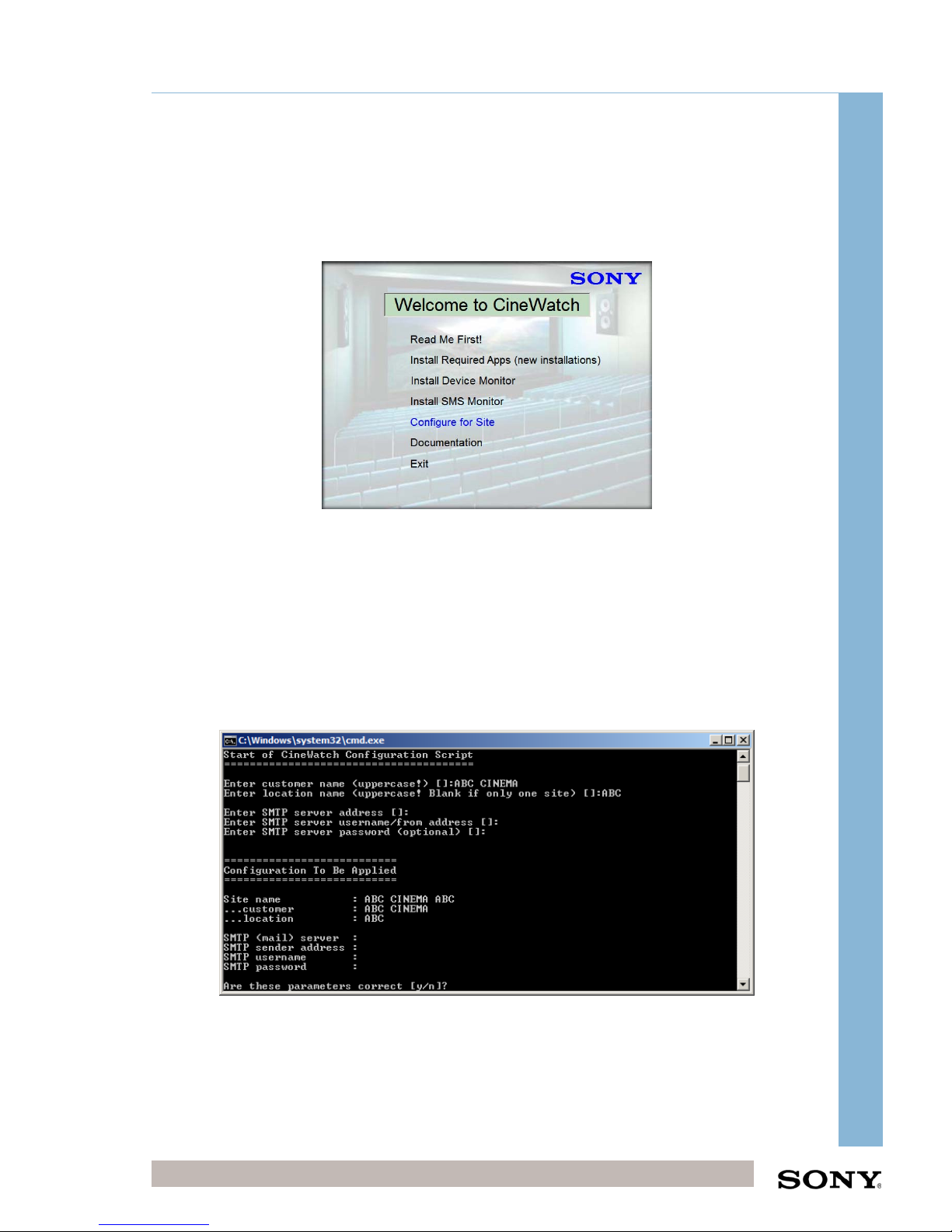
8.4 CineWatch Device Monitor Site Name Settings
Go to C:\CHIPS Utilities\Cinewatch\Windows Disk Files
Double click on autorun application
Click Configure for Site
Enter the Customer name in capitals
Enter the location in capitals
Enter the SMTP server address if known (can be done later)
Enter the SMTP Server UN/from address if known (can be done later)
Enter SMTP password (can be done later)
Type Y to confirm, wait for CMD to and close by itself.
Exit autorun
Site Name now set for CineWatch Device Monitor
Update Device Monitor
Page 38
Integrator Training, UK
Confidential Digital Cinema Deployment 38 of 49
October 15
CHIPS Stand-Alone Integrator Installation Training (CHIPS)
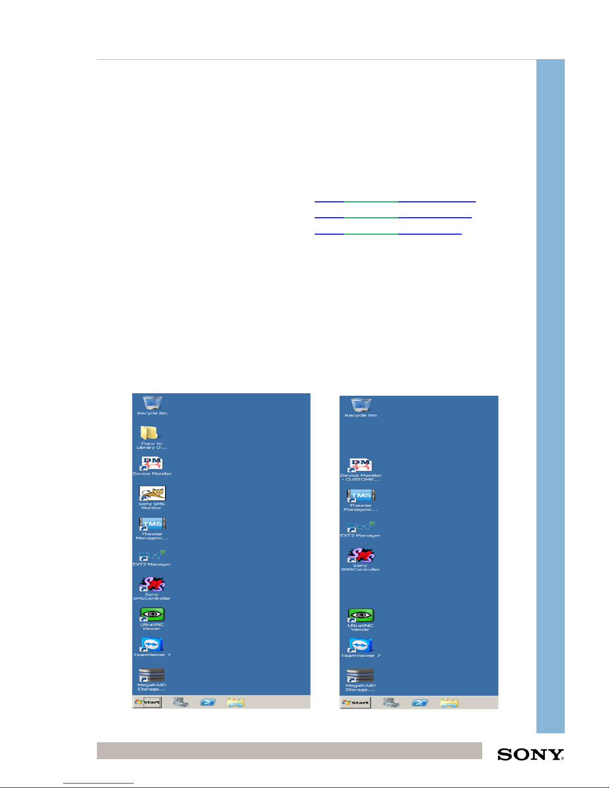
8.5 TMS Server Desktop Shortcuts
Create the following desktop shortcuts on the TMS Server desktop. If shortcuts are
required on the TMS workstation create these also. The below are the main Shortcuts
required to run the TMS system.
onTMSserver,thelinksbelowarealready
createdaspartoftheserverimageinthe
Administratoraccount
onTMSWorkstationthefollowingshortcuts
willneedsetting.
http://localhost:8400/TMS‐Server
http://TMSServerIP:8400/TMS‐Server
http://localhost/Device_Monitor
http://TMSServerIP/Device_Monitor
http://localhost/SMS_Monitor
http://TMSServerIP/SMS_Monitor
onTMSserver,thelinksbelowarealready
createdaspartoftheserverimageinthe
TMSUseraccount.
http://localhost:8400/TMS‐Server
http://localhost/Device_Monitor
TMS Administrator TMS User
Desktop Background Desktop Background
Page 39
Integrator Training, UK
Confidential Digital Cinema Deployment 39 of 49
October 15
CHIPS Stand-Alone Integrator Installation Training (CHIPS)
8.6 Paragon ExtFS driver
Please refer to Paragon ExtFs Installation.pdf instructions.
8.6.1 All NTP addresses
Check each device has the correct NTP settings pointing to the TMS server IP
address.
On windows machines this can be found by clicking on the clock and “changing date
and time settings” then clicking on the internet time tab.
On Sony projectors this can be found in maintenance > Clock settings.
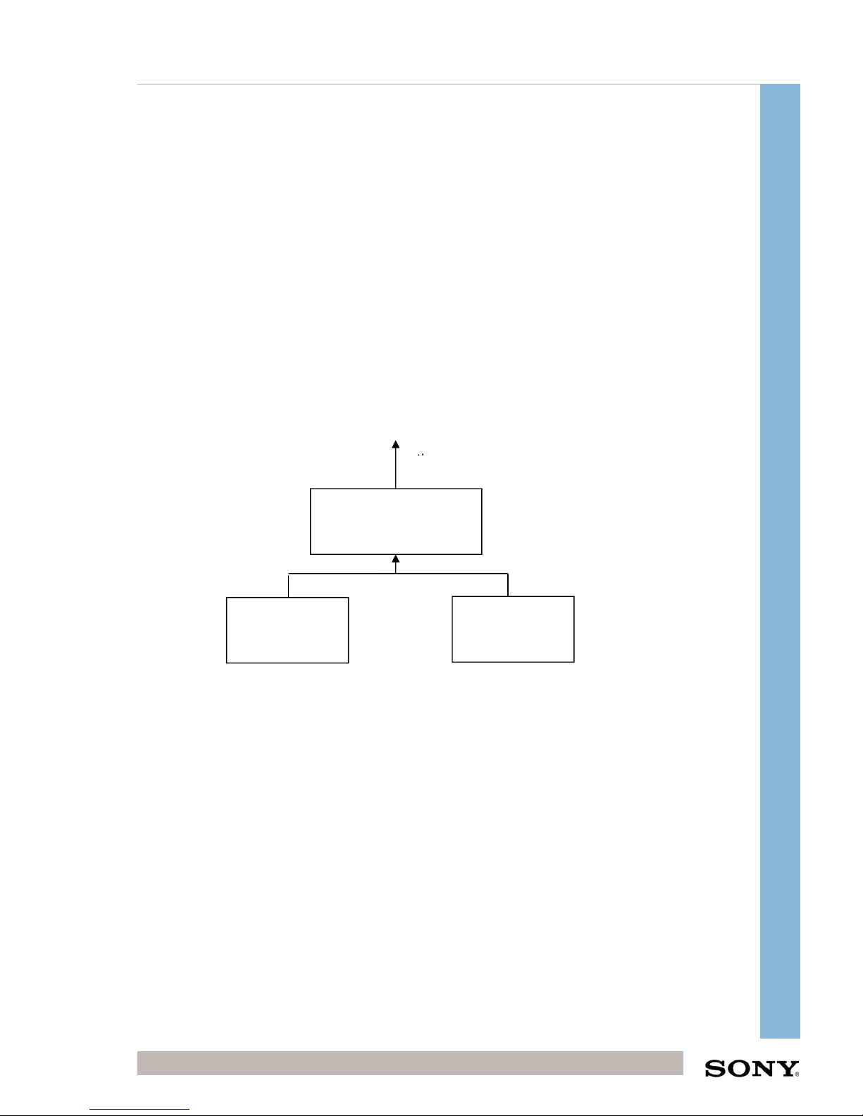
All devices within the system that require NTP are synchronised to the TMS Server.
The TMS Server is then synchronised to an external NTP. See overview diagram
below:
9 Please set the Windows Time service is set to automatic
(delayed start).
e.g.
time.windows.com
Site X
TMS Server
Site X
TMS Client
Site X
Projectors
1-32max
Page 40

Integrator Training, UK
Confidential Digital Cinema Deployment 40 of 49
October 15
CHIPS Stand-Alone Integrator Installation Training (CHIPS)
Final TMS Server Configuration
9.1 TMS Server Windows Login
Log on to the TMS Server using the site specific username and password.
S0nytms01 (Site name has a capital first letter)
9.2 TMS Service is Running
Go to Start menu -> Administrative tools -> Services -> tms, restart the service to
check that it is running correctly.
9.3 Windows Time Service is Running
Go to Start menu -> Administrative tools -> Services -> Windows Time, restart the
service to check that it is running correctly. This service is used for NTP across the
system. Set to delayed automatic start.
9.4 Firewall Settings
The Windows firewall will be disabled, check that the Windows Service is also
disabled.
Page 41

Integrator Training, UK
Confidential Digital Cinema Deployment 41 of 49
October 15
CHIPS Stand-Alone Integrator Installation Training (CHIPS)
10 Sony Projector Preparation for TMS
There is some configuration of the Media Block (LMT) in order for it to correctly
interact with the TMS. These steps should be completed after the projector has been
aligned and setup using the SRXC software.
The following setups require an IP address schema. If customer does not have a predefined one, please use the default schema on page 14.
10.1 Screen to Screen (S2S) Network Setup
Log on to the Media Block using the Projection Touchpanel (PJT)
(UN: super, PW: 0955)
Menu > Content > S2S Network Setup
Enter the following parameters:
IP Address: <Projector S2S IP address from the IP Schema>
Subnet Mask <Assume to be 255.255.255.0 unless otherwise stated>
Default Gateway < Default Gateway IP address from the IP Schema>
10.2 Screen to Screen Source Setup
This sets up the sources from which each projector can ingest material. Therefore the
projector needs to have all the other projectors setup as sources. For example
projector 1 of 9 screens would need screen 2-8 setup as sources.
Log on to the PJT (UN: super, PW: 0955)
Menu > Content > S2S Source
Enter a Name: scr2 (do not use any spaces)
IP Address: <Projector TMS IP address from the IP Schema>
Add all other screens to the S2S sources.
10.3 NTP Setup
Log on to the PJT (UN: super, PW: 0955)
Menu > Maintenance > Clock Settings
Enter the following:
IP Address: <TMS Server IP Address>
Save Settings.
Page 42

Integrator Training, UK
Confidential Digital Cinema Deployment 42 of 49
October 15
CHIPS Stand-Alone Integrator Installation Training (CHIPS)
10.4 Network Setup
Log on to the PJT (UN: super, PW: 0955)
Menu > Maintenance > Network Setup
Enter the following parameters:
IP Address: <Projector TMS IP Address from the IP Schema>
Subnet Mask <Assume to be 255.255.255.0 unless otherwise stated>
Default Gateway < Default Gateway IP address from the IP Schema >
DNS Address Assignment <Leave blank unless otherwise stated>
Save Settings.
Once the settings have been saved the SMS server will fully reboot, wait for the login
screen with login button to re-appear before proceeding.
After setup has been completed fully shutdown the Projector and restart.
10.5 SMSManager_custom.ini file change
There is a ini file in the projector that needs to be changed so that the TMS purge
routines for the schedule run correctly. This needs to be completed on the first
installed projector, after this the SMS configuration can be exported from the first
projector to the next with the ini file change completed.
Required software:
WinSCP software
Customise ini file.exe
Method:
Run Customise ini file.exe and follow instructions.
Connect to SMS IP via WinSCP port 22
Replace the new SMSMgrServer_custom.ini at /home/sms/apps/conf/
Restart SMS server
Page 43
Integrator Training, UK
Confidential Digital Cinema Deployment 43 of 49
October 15
CHIPS Stand-Alone Integrator Installation Training (CHIPS)
11 SMS-C Configuration
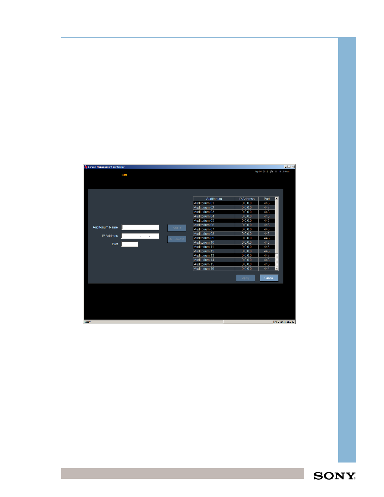
11.1 Initial Login configuration
Username local
Password config
Leave the select auditorium
Login
As part of your TMS system, you will find that 20 auditoriums have already been set
with IP addresses of 0.0.0.0. This is for your convenience and will save time when
configuring on site.
Select Auditorium 01
Select “Remove”
Edit IP address
Select “Add”
Select “Apply”
Repeat until all Auditoriums have been set.
Page 44
Integrator Training, UK
Confidential Digital Cinema Deployment 44 of 49
October 15
CHIPS Stand-Alone Integrator Installation Training (CHIPS)
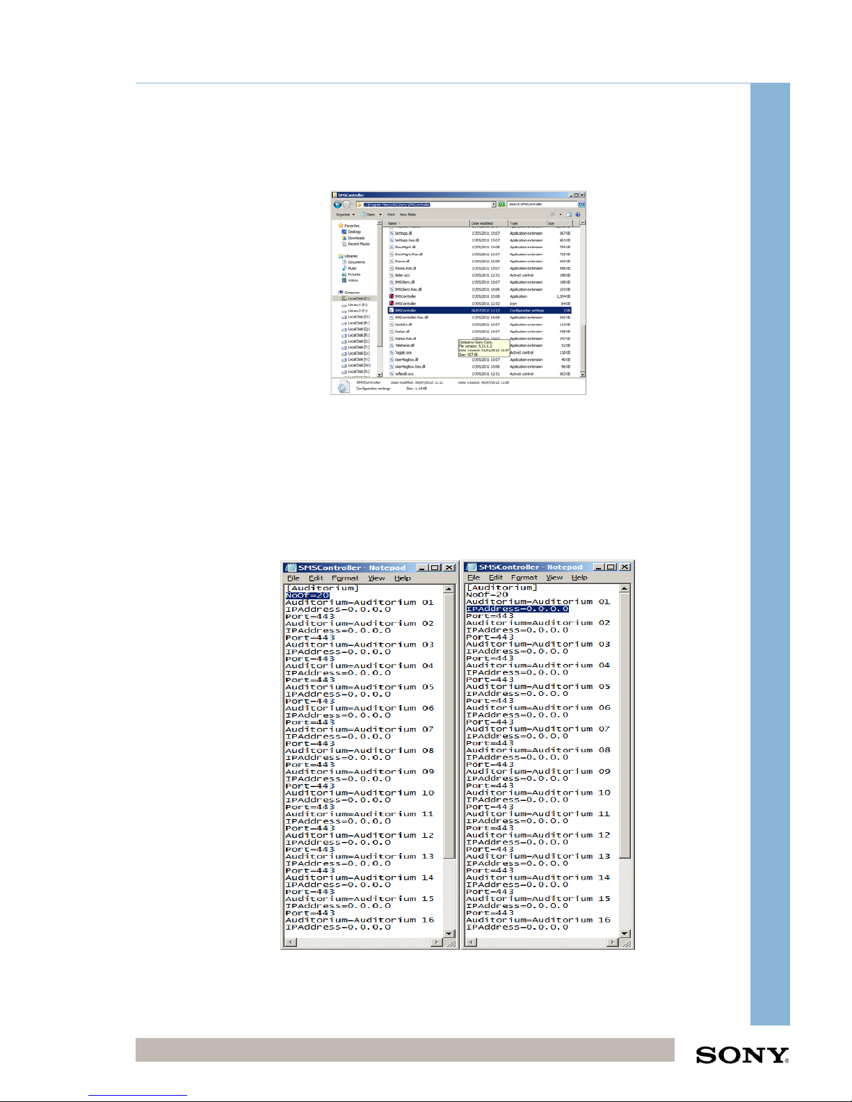
It is also possible to setup SMSC in the Administrator account by navigating to
C:\Program Files (x86)\Sony\SMSController and opening SMSController
configuration file.
In Notepad,
Change the “NoOf=Total number of Auditoriums”
Change “IPAddress=IP address of auditorium as listed in IP schema”
Save and close Notepad
Start SMSC and login using “local” and “config”. You will now see all Auditoriums set.
NB: This method can only be used whilst logged in as Administrator. For Standard
user accounts, the first method will have to be used on the previous page.
Page 45

Integrator Training, UK
Confidential Digital Cinema Deployment 45 of 49
October 15
CHIPS Stand-Alone Integrator Installation Training (CHIPS)
11.2 SMS-C Folder setting on SMS-C
11.2.1 SMS-C ‘Export’ Folder Settings
This is a folder share for exporting Auditorium Configurations and can be utilised by
Integrators. Once one Auditorium has been configured, the Exported configuration
can be used on other Auditoriums using the Export Folder.
Logon to the SMS-C -> Settings -> Folders
Create the following folder using the following settings:
Name: Export
Storage Type: Network Share
Usage: Any
SMS Server Local Path /mnt/Export
SMS Server Device/Network Path \\<IP Address of TMS Server>\Export
Device Access Information
Domain
Username Administrator
Password S0nytms01
Click on Add, Apply
Page 46

Integrator Training, UK
Confidential Digital Cinema Deployment 46 of 49
October 15
CHIPS Stand-Alone Integrator Installation Training (CHIPS)
12 TMS Client Workstation Configuration
12.1 Hardware Setup
The TMS workstation is a standard PC workstation. This workstation will be used by
the projectionist to access the TMS GUI. The workstation is usually situated on a
projectionist desk near the TMS rack however as long as the workstation has a
network connection to the TMS switch it can be situated anywhere in the cinema
building. Sony only provides one workstation per TMS system however it is possible
for the customer to add more at their own expense.
12.2 General Setup
12.2.1 Initial Windows Configuration
1) Enter regional details of the TMS
2) Enter the customer name for the username (Do not use spaces)
3) Computer Name: TMS-CLIENT
4) Username: Administrator
5) Password: S0nytms01
6) Change the computer and workgroup name:
Computer name: TMS-CLIENT
Workgroup name: CHIPS
N.B. To do this right click on my computer select properties then change, enter the
details above.
7) Restart workstation.
8) Change Resolution of screen to 1280x1024 (required for TMS software).
9) Set clock to correct time and time zone.
10) Turn off Automatic Updates and Windows problem reporting.
12.2.2 Firewall Settings
1) Turn off Windows Firewall and set Windows Firewall service to Manual.
2) If the firewall has to be on continue with step 3) otherwise go to 5).
3) Open the following ports:
Go to Control Panel -> Windows Firewall -> Allow a program through windows
firewall ->Exceptions Tab -> Add Port
Name NTP Name TMS
Port 123 Port 8400
Page 47

Integrator Training, UK
Confidential Digital Cinema Deployment 47 of 49
October 15
CHIPS Stand-Alone Integrator Installation Training (CHIPS)
Protocol UDP Protocol TCP
4) Enable ICMP messages by going to windows firewall -> Advanced -> ICMP
messages and selecting all options, Apply, OK.
The firewall could be turned off all together as it is not connected to the outside
world. This will avoid any firewall issues regarding the TMS Client.
5) Windows Firewall configuration is now completed.
12.2.3 Software Prerequisites
Make sure that the following software is installed on the TMS Client PC:
Adobe Flash Player 11.1 (Minimum) (Win and Winax files)
Adobe Reader 8 (Minimum) (or other PDF reader to read manuals)
Internet Explorer 7+ or Firefox 3 (Minimum)
UltraVNC Server and viewer (32 bit) should be installed so that the
workstation be accessed from the TMS Server for remote support.
12.3 Network Setup
To change network credentials go to Control Panel -> Network connections -> right
click Properties, then Properties of IP4 and enter the IP address details manually:
IP Address <IP Address of TMS Client PC>
Subnet mask: 255.255.255.0
Default Gateway: < Default Gateway IP address from the IP Schema>
12.4 NTP Client Setup
To synchronise the time with NTP server double click on Clock -> Change date and
time settings -> Internet Time -> Change Settings and enter the IP address of the
TMS Server.
12.5 SMSC Installation
Install SMSC on the Client PC using the standard settings. Contact the Sony project
team to make sure it is the correct version for the LMT that is installed onsite.
12.5.1 Initial Login configuration
Username local
Password config
Page 48
Integrator Training, UK
Confidential Digital Cinema Deployment 48 of 49
October 15
CHIPS Stand-Alone Integrator Installation Training (CHIPS)
Ignore the “select auditorium” tab
Login
Enter the following details for each auditorium
Auditorium name Auditorium X
IP Address <IP of Auditorium X”
Port 443
12.6 Create Shortcuts
Create a shortcut on the Desktop for the following:
SMSC (if needed)
http://TMS‐ServerIP:8400/TMS‐Server
Error! Hyperlink reference not valid.
13 Hardware Test Procedures
Complete the following tests to check that the CHIPS rack is powered up correctly
and the network connectivity is established.
Hardware Test Procedures
Network Tests Procedure Expected Result If Test Fails
Test
Completed
TMS Server to TMS
Client PC
Open command
prompt on TMS Server
Enter ping <IP Address
of TMS Client PC>
TMS Client PC
replies to ping
Check network
cabling and
settings
TMS Server to
Projectors
Open command
prompt on TMS Server
Enter ping <IP Address
of Projector>
Projector replies to
ping
Check network
cabling and
settings
Check TMS Server
teaming
configuration
Open Task Manager
check that the
Application network
team is running at 4Gb
There is a team
connection and it is
running at 4Gb
Contact Sony
Engineer
UPS Tests Procedure Expected Result If Test Fails
Test
Completed
Will the UPS
shutdown the system
if there is a power
cut?
Make sure the UPS is
fully charged and on
load protected mode.
Then disconnect the
power supply to the
UPS.
UPS will begin to
bleep and a
notification will
appear on the TMS
and CineWatch
Servers. After 20
minutes the TMS
and CineWatch
Servers will be
shutdown.
Check network
connection from
UPS to switch.
Ping UPS.
Configure the
Netwatch
software on the
TMS and
CineWatch
Servers.
Page 49
Integrator Training, UK
Confidential Digital Cinema Deployment 49 of 49
October 15
CHIPS Stand-Alone Integrator Installation Training (CHIPS)
NTP Tests Procedure Expected Result If Test Fails
Test
Completed
Are all the clocks
synchronised with
the TMS Server?
Double click on clock
on server -> internet
time
The clock is set to
look at the TMS
Server IP address
and is
synchronised
Check that the
TMS Server has
been setup as a
NTP server.
Check network
connection and
settings.
 Loading...