

Page 1

TMR-RF950R
SERVICE MANUAL
Ver 1.0 1998. 06
TMR-RF950R is transmitter
unit in MDR-RF950RK.
SPECIFICATIONS
US Model
Canadian Model
MICROFILM
Notes on chip component replacement
• Never reuse a disconnected chip component.
• Notice that the minus side of a tantalum capacitor may be damaged by heat.
TRANSMITTER
Page 2
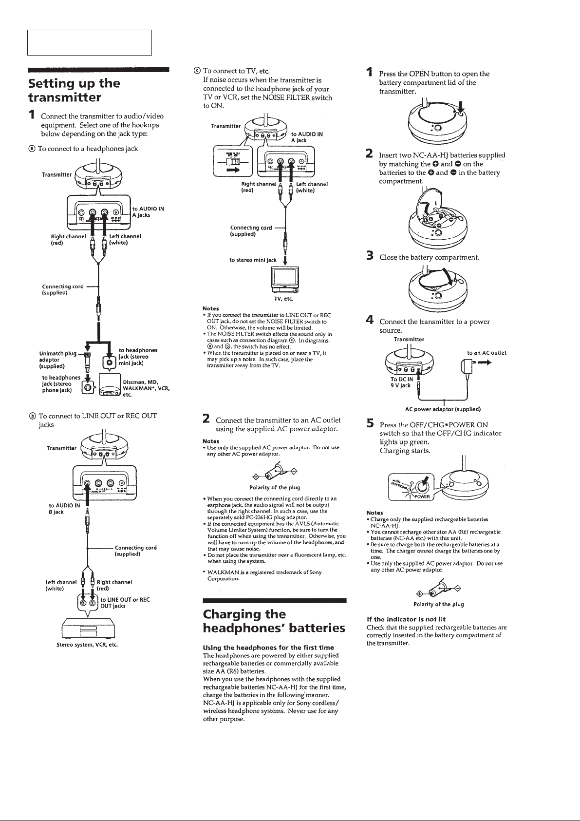
This section is extracted from
instruction manual.
SECTION 1
GENERAL
– 2 –
Page 3

– 3 –
Page 4

SECTION 2
r
ELECTRICAL ADJUSTMENTS
Note:
The adjustments should be performed in the order given.
2-1. Transmission Frequency Check and Adjustment
Preparation:
AF OSC
ATT
+
+
–
+
–
–
TMR-RF950R
Trans-
600
AUDIO IN (J403: Lch)
1 kHz 40 mVrms
mitter
Ω
frequency counte
+
–
Procedure:
1. Turn OFF the noise filter switch (S401) on the TX-BASE board.
2. Enter 1 kHz 40 mVrms signal only to the Lch (J403) on the TX-BASE board.
3. Connect a rod antenna to the input of frequency counter, and adjust its length to about 8 cm.
4. Install the set in the vicinity of frequency counter, and check that the frequency on each channel is as specified value.
Specified value:
CH1 913.0 MHz ± 100 kHz
CH2 914.0 MHz ± 100 kHz
CH3 915.0 MHz ± 100 kHz
5. If out of the specified value, adjust the frequency by rotating RV402 and RV403 on the TX-BASE board.
6. After adjustment, recheck the frequency on CH1, CH2, and CH3.
Adjustment Location: TX-BASE board (See page 6.)
2-2. Degree of Modulation of Subcarrier (L – R) Check and Adjustment
Preparation:
AF OSC
+
–
AUDIO IN (J403: Lch)
1 kHz 316 mVrms
Ω
TMR-RF950R
Transmitter
+
–
ATT
+
–
600
[TX-BASE board] – Conductor Side –
AC voltmeter
– 4 –
Page 5

Procedure:
r
RV405
Subcarrier Level
and Frequency
Adjustment
RV402
RV403
Transmission
Frequency
Adjustment
RV404
Degree of
Modulation of
Main Carrier (L + R)
Adjustment
(Please refer to
MDR-RF950
Service manual for
this adjustment)
RV401
Degree of
Modulation of
Subcarrier (L – R)
Adjustment
NOISE FILTER
OFF
˜
ON
J402
(Rch)
J403
(Lch)
S402
CHANNEL
CH1
˜
CH2
˜
CH3
S401
[TX-BASE board] – Component Side –
1. Turn OFF the noise filter switch (S401) on the TX-BASE board.
2. Set the channel select switch (S402) on the TX-BASE board to CH2.
3. Enter 1 kHz 316 mVrms signal only to the Lch (J403) on the TX-BASE board.
4. Using on AC voltmeter, measure the voltage of IC403 pin 1 on the TX-BASE board to check that it is 220 mVrms to 250 mVrms.
5. If out of the specified value, adjust the voltage by rotating RV401 on the TX-BASE board so as to attain 235 mVrms.
Adjustment Location: TX-BASE board (See page 6.)
2-3. Subcarrier Level and Frequency Check and Adjustment
Preparation:
Adjustment Location:
AF OSC
+
–
AUDIO IN (J403: Lch)
1 kHz 316 mVrms
ATT
+
+
–
–
600
[TX-BASE board] – C0nductor Side–
Ω
TMR-RF950R
Transmitter
oscilloscope
+
OUT
–
coaxial cable
frequency counte
IN
Procedure:
1. Turn OFF the noise filter switch (S401) on the TX-BASE board.
2. Set the channel select switch (S402) on the TX-BASE board to CH2.
3. Enter 1 kHz 316 mVrms signal only to the Lch (J403) on the TX-BASE board.
4. Connect a frequency counter and an oscilloscope between emitter of Q409 and ground on the TX-BASE board.
5. Turn off the input to the Lch on the TX-BASE board. (If the input is not turned off, the subcarrier is modulated and it cannot be
measured.)
6. Check that the frequency counter indicates 48 kHz to 52 kHz.
7. If out of the specified value, adjust the frequency by rotating R V405 on the TX-B ASE board so as to attain 50 kHz. Also, check that the
waveform on oscilloscope is as shown below.
3.6 Vp-p ± 0.2 V
Note:
As the transmitter turns off automatically about one minute after the input to Lch of transmitter was turned off, checking and adjustment must be performed
within one minute. If it turned off automatically, again turn on the input to Lch to turn on the transmitter automatically, then turn off the input to Lch and
perform checking and adjustment.
– 5 – – 6 –
Page 6

Page 7

Page 8

SECTION 4
EXPLODED VIEW
TX-BASE
SECTION 5
ELECTRICAL PARTS LIST
NOTE:
• -XX and -X mean standardized parts, so they
may have some difference from the original
one.
• Color Indication of Appearance Parts
Example:
KNOB, BALANCE (WHITE) . . . (RED)
↑↑
Parts Color Cabinet's Color
• Items marked “*” are not stocked since they
are seldom required for routine service. Some
delay should be anticipated when ordering
these items.
• The mechanical parts with no reference number in the exploded views are not supplied.
1
7
8
9
6
not supplied
11
10
5
4
3
2
5
1
5
Ref. No. Part No. Description Remark Ref. No. Part No. Description Remark
1 3-320-382-01 FOOT, RUBBER
2 4-994-922-21 CABINET (LOWER) (US)
2 4-994-922-41 CABINET (LOWER) (Canadian)
* 3 A-4542-515-A TX-BASE BOARD, COMPLETE
4 4-994-931-01 BUTTON, POWER
5 7-685-105-19 SCREW +P 2X8 TYPE2 NON-SLIT
6 4-987-658-02 SPRING, BATTERY COIL
7 4-994-923-01 LID, BATTERY CASE
8 4-994-925-01 CAP, ANTENNA
9 4-994-921-21 CABINET (UPPER)
10 4-993-652-01 BUTTON, OPEN
* 11 4-994-924-01 PIPE, ANTENNA
NOTE:
• Due to standardization, replacements in the
parts list may be different from the parts specified in the diagrams or the components used
on the set.
• -XX and -X mean standardized parts, so they
may have some difference from the original
one.
• RESISTORS
All resistors are in ohms.
METAL: Metal-film resistor.
METAL OXIDE: Metal oxide-film resistor.
F: nonflammable
Ref. No. Part No. Description Remark
* A-4542-515-A TX-BASE BOARD, COMPLETE
************************
< CAPACITOR >
C401 1-163-809-11 CERAMIC CHIP 0.047uF 10% 25V
C402 1-119-866-11 CERAMIC CHIP 0.68uF 10% 10V
C403 1-163-009-11 CERAMIC CHIP 0.001uF 10% 50V
C405 1-163-009-11 CERAMIC CHIP 0.001uF 10% 50V
C407 1-124-463-00 ELECT 0.1uF 20% 50V
C408 1-163-037-11 CERAMIC CHIP 0.022uF 10% 25V
C409 1-124-257-00 ELECT 2.2uF 20% 50V
C410 1-124-434-00 ELECT 220uF 20% 4V
C411 1-163-809-11 CERAMIC CHIP 0.047uF 10% 25V
C412 1-119-866-11 CERAMIC CHIP 0.68uF 10% 10V
C413 1-163-009-11 CERAMIC CHIP 0.001uF 10% 50V
C414 1-163-251-11 CERAMIC CHIP 100PF 5% 50V
C415 1-163-009-11 CERAMIC CHIP 0.001uF 10% 50V
C416 1-124-589-11 ELECT 47uF 20% 16V
C417 1-124-257-00 ELECT 2.2uF 20% 50V
C418 1-163-037-11 CERAMIC CHIP 0.022uF 10% 25V
C419 1-124-589-00 ELECT 47uF 20% 16V
C420 1-124-464-11 ELECT 0.22uF 20% 50V
C422 1-163-131-00 CERAMIC CHIP 390PF 5% 50V
C423 1-163-131-00 CERAMIC CHIP 390PF 5% 50V
C424 1-124-257-00 ELECT 2.2uF 20% 50V
C425 1-163-005-11 CERAMIC CHIP 470PF 10% 50V
C426 1-104-664-11 ELECT 47uF 20% 16V
C428 1-126-933-11 ELECT 100uF 20% 16V
C431 1-163-251-11 CERAMIC CHIP 100PF 5% 50V
C433 1-163-021-00 CERAMIC CHIP 0.01uF 10% 50V
C434 1-163-037-11 CERAMIC CHIP 0.022uF 10% 25V
C435 1-104-664-11 ELECT 47uF 20% 16V
C436 1-126-962-11 ELECT 3.3uF 20% 50V
C437 1-124-233-11 ELECT 10uF 20% 16V
C439 1-126-933-11 ELECT 100uF 20% 16V
C440 1-128-551-11 ELECT 22uF 20% 25V
C443 1-124-434-00 ELECT 220uF 20% 4V
C444 1-163-021-00 CERAMIC CHIP 0.01uF 10% 50V
C445 1-163-021-00 CERAMIC CHIP 0.01uF 10% 50V
< DIODE >
D401 8-719-812-41 LED TLR124 (ON)
D402 8-719-938-67 LED GL-3EG8 (OFF/CHG)
D404 8-719-991-33 DIODE 1SS133T-77
D405 8-719-991-33 DIODE 1SS133T-77
D406 8-719-109-85 DIODE RD5.1ES-B2
• Items marked “*” are not stocked since they
are seldom required for routine service.
Some delay should be anticipated when ordering these items.
• SEMICONDUCTORS
In each case, u: µ, for example:
uA. . : µA. . uPA. . : µPA. .
uPB. . : µPB. . uPC. . : µPC. .
uPD. . : µPD. .
• CAPACITORS
uF: µF
• COILS
uH: µH
(Including VCO BOARD)
When indicating parts by reference
number, please include the board.
Ref. No. Part No. Description Remark
D407 8-719-991-33 DIODE 1SS133T-77
< IC >
IC401 8-759-998-71 IC BA3308F
IC402 8-759-708-05 IC NJM78L05A
IC403 8-759-701-39 IC NJM3404AM
< JACK >
J401 1-566-822-21 JACK (AUDIO IN, B)
J402 1-563-866-21 JACK, PIN 1P (AUDIO IN, A (R))
J403 1-563-866-41 JACK, PIN 1P (AUDIO IN, A (L))
J404 1-778-380-11 JACK, DC (POLARITY UNIFIED TYPE)
< SHORT >
JR401 1-216-295-00 SHORT 0
JR402 1-216-295-00 SHORT 0
JR403 1-216-295-00 SHORT 0
JR404 1-216-295-00 SHORT 0
JR405 1-216-295-00 SHORT 0
JR406 1-216-295-00 SHORT 0
JR407 1-216-295-00 SHORT 0
< COIL >
L401 1-414-223-11 INDUCTOR 470uH
L411 1-414-223-11 INDUCTOR 470uH
< FILTER >
LF401 1-403-601-21 FILTER, COMMON MODE
LF402 1-411-236-11 FILTER, EMI
< TRANSISTOR >
Q401 8-729-119-78 TRANSISTOR 2SC403SP-51
Q403 8-729-119-78 TRANSISTOR 2SC403SP-51
Q404 8-729-119-76 TRANSISTOR 2SA1175-HFE
Q405 8-729-119-78 TRANSISTOR 2SC403SP-51
Q406 8-729-119-76 TRANSISTOR 2SA1175-HFE
Q407 8-729-119-78 TRANSISTOR 2SC403SP-51
Q408 8-729-119-78 TRANSISTOR 2SC403SP-51
Q409 8-729-119-78 TRANSISTOR 2SC403SP-51
< RESISTOR >
R401 1-216-085-00 METAL CHIP 33K 5% 1/10W
R402 1-216-304-11 METAL CHIP 3.3 5% 1/10W
R403 1-216-025-00 RES,CHIP 100 5% 1/10W
R404 1-216-085-00 METAL CHIP 33K 5% 1/10W
R405 1-216-025-00 RES,CHIP 100 5% 1/10W
(DC IN 9V)
– 11 –
– 12 –
Page 9

TX-BASE VCO
Ref. No. Part No. Description Remark Ref. No. Part No. Description Remark
R467 1-216-089-00 RES,CHIP 47K 5% 1/10W
R406 1-216-085-00 METAL CHIP 33K 5% 1/10W
R407 1-216-049-11 RES,CHIP 1K 5% 1/10W
R408 1-216-049-11 RES,CHIP 1K 5% 1/10W
R409 1-216-057-00 METAL CHIP 2.2K 5% 1/10W
R410 1-216-065-00 RES,CHIP 4.7K 5% 1/10W
R411 1-216-085-00 METAL CHIP 33K 5% 1/10W
R412 1-216-304-11 METAL CHIP 3.3 5% 1/10W
R413 1-216-025-00 RES,CHIP 100 5% 1/10W
R414 1-216-085-00 METAL CHIP 33K 5% 1/10W
R415 1-216-025-00 RES,CHIP 100 5% 1/10W
R416 1-216-085-00 METAL CHIP 33K 5% 1/10W
R417 1-216-049-11 RES,CHIP 1K 5% 1/10W
R418 1-216-049-11 RES,CHIP 1K 5% 1/10W
R419 1-216-057-00 METAL CHIP 2.2K 5% 1/10W
R420 1-216-129-00 METAL CHIP 2.2M 5% 1/10W
R421 1-216-081-00 METAL CHIP 22K 5% 1/10W
R422 1-216-121-00 RES,CHIP 1M 5% 1/10W
R425 1-216-033-00 METAL CHIP 220 5% 1/10W
R426 1-216-061-00 METAL CHIP 3.3K 5% 1/10W
R427 1-216-097-00 RES,CHIP 100K 5% 1/10W
R468 1-216-049-11 RES,CHIP 1K 5% 1/10W
R469 1-216-081-00 METAL CHIP 22K 5% 1/10W
R470 1-216-045-00 METAL CHIP 680 5% 1/10W
< VARIABLE RESISTOR >
RV401 1-241-764-11 RES, ADJ, CERMET 10K
RV402 1-241-764-11 RES, ADJ, CERMET 10K
RV403 1-241-764-11 RES, ADJ, CERMET 10K
RV404 1-241-762-11 RES, ADJ, CERMET 2.2K
RV405 1-241-762-11 RES, ADJ, CERMET 2.2K
< SWITCH >
S401 1-692-181-11 SWITCH, SLIDE (NOISE FILTER)
S402 1-771-373-11 SWITCH, SLIDE (1C-3P) (CHANNEL)
S403 1-554-419-00 SWITCH, PUSH (1 KEY) (POWER)
************************************************************
VCO BOARD
**********
(Included in TX-BASE BOARD, COMPLETE)
R428 1-216-115-00 METAL CHIP 560K 5% 1/10W
R429 1-216-089-00 RES,CHIP 47K 5% 1/10W
R430 1-216-133-00 METAL CHIP 3.3M 5% 1/10W
R431 1-216-097-00 RES,CHIP 100K 5% 1/10W
R432 1-216-081-00 METAL CHIP 22K 5% 1/10W
R433 1-216-097-00 RES,CHIP 100K 5% 1/10W
R435 1-216-033-00 METAL CHIP 220 5% 1/10W
R436 1-216-061-00 METAL CHIP 3.3K 5% 1/10W
R437 1-216-097-00 RES,CHIP 100K 5% 1/10W
R438 1-216-061-00 METAL CHIP 3.3K 5% 1/10W
R439 1-216-097-00 RES,CHIP 100K 5% 1/10W
R440 1-216-182-00 RES,CHIP 220 5% 1/8W
R441 1-216-061-00 METAL CHIP 3.3K 5% 1/10W
R442 1-216-073-00 METAL CHIP 10K 5% 1/10W
R443 1-216-085-00 METAL CHIP 33K 5% 1/10W
R444 1-216-073-00 METAL CHIP 10K 5% 1/10W
R445 1-216-061-00 METAL CHIP 3.3K 5% 1/10W
R446 1-216-049-11 RES,CHIP 1K 5% 1/10W
R447 1-216-049-11 RES,CHIP 1K 5% 1/10W
R448 1-216-093-00 METAL CHIP 68K 5% 1/10W
R449 1-216-079-00 METAL CHIP 18K 5% 1/10W
R450 1-216-079-00 METAL CHIP 18K 5% 1/10W
R451 1-216-055-00 METAL CHIP 1.8K 5% 1/10W
R452 1-216-081-00 METAL CHIP 22K 5% 1/10W
R453 1-216-182-00 RES,CHIP 220 5% 1/8W
< CAPACITOR >
C101 1-162-927-11 CERAMIC CHIP 100PF 5% 50V
C102 1-162-906-11 CERAMIC CHIP 1.5PF 0.25PF 50V
C103 1-162-906-11 CERAMIC CHIP 1.5PF 0.25PF 50V
C104 1-162-909-11 CERAMIC CHIP 4PF 0.25PF 50V
C106 1-162-927-11 CERAMIC CHIP 100PF 5% 50V
C107 1-162-906-11 CERAMIC CHIP 1.5PF 0.25PF 50V
C108 1-162-904-11 CERAMIC CHIP 0.5PF 0.25PF 50V
C109 1-163-275-11 CERAMIC CHIP 0.001uF 5% 50V
C110 1-163-251-11 CERAMIC CHIP 100PF 5% 50V
C111 1-163-085-00 CERAMIC CHIP 2PF 50V
C112 1-163-251-11 CERAMIC CHIP 100PF 5% 50V
C113 1-163-085-00 CERAMIC CHIP 2PF 50V
C114 1-163-217-11 CERAMIC CHIP 1PF 0.25PF 50V
C115 1-163-220-11 CERAMIC CHIP 3PF 0.25PF 50V
C116 1-163-085-00 CERAMIC CHIP 2PF 50V
C117 1-163-251-11 CERAMIC CHIP 100PF 5% 50V
C118 1-163-251-11 CERAMIC CHIP 100PF 5% 50V
C119 1-163-220-11 CERAMIC CHIP 3PF 0.25PF 50V
C120 1-163-220-11 CERAMIC CHIP 3PF 0.25PF 50V
C121 1-163-091-00 CERAMIC CHIP 8PF 50V
C122 1-162-934-11 CERAMIC CHIP 3PF 0.25PF 50V
C123 1-163-275-11 CERAMIC CHIP 0.001uF 5% 50V
C124 1-163-251-11 CERAMIC CHIP 100PF 5% 50V
R454 1-216-057-00 METAL CHIP 2.2K 5% 1/10W
R455 1-216-057-00 METAL CHIP 2.2K 5% 1/10W
R456 1-216-057-00 METAL CHIP 2.2K 5% 1/10W
R457 1-216-025-00 RES,CHIP 100 5% 1/10W
R458 1-216-100-00 RES,CHIP 130K 5% 1/10W
R460 1-216-023-00 METAL CHIP 82 5% 1/10W
R461 1-216-035-00 METAL CHIP 270 5% 1/10W
R462 1-216-035-00 METAL CHIP 270 5% 1/10W
R463 1-216-037-00 METAL CHIP 330 5% 1/10W
R464 1-216-073-00 METAL CHIP 10K 5% 1/10W
R465 1-216-073-00 METAL CHIP 10K 5% 1/10W
R466 1-216-113-00 METAL CHIP 470K 5% 1/10W
< DIODE >
D101 8-713-101-23 DIODE 1T365-04-T8A
< COIL >
L101 1-416-776-11 COIL, AIR-CORE
L102 1-411-961-21 INDUCTOR 10nH
L103 1-416-795-11 COIL, AIR-CORE
L105 1-416-777-11 COIL, AIR-CORE
L106 1-416-759-11 COIL, AIR-CORE
L107 1-411-961-21 INDUCTOR 10nH
– 13 –
Page 10

TMR-RF950R
VCO
Ref. No. Part No. Description Remark
< TRANSISTOR >
Q101 8-729-230-81 TRANSISTOR 2SC3606
Q102 8-729-230-81 TRANSISTOR 2SC3606
Q103 8-729-230-81 TRANSISTOR 2SC3606
< RESISTOR >
R101 1-216-057-00 METAL CHIP 2.2K 5% 1/10W
R102 1-216-049-11 RES,CHIP 1K 5% 1/10W
R103 1-216-046-00 METAL CHIP 750 5% 1/10W
R104 1-216-085-00 METAL CHIP 33K 5% 1/10W
R105 1-216-017-00 RES,CHIP 47 5% 1/10W
R106 1-216-009-00 METAL CHIP 22 5% 1/10W
R107 1-216-097-00 METAL CHIP 100K 5% 1/10W
< TRIMMER >
TC101 1-141-327-11 CAP, CHIP TYPE TRIMMER 10PF
< CAPACITOR >
THC101 1-125-825-11 CERAMIC 0.001MF 50V
THC102 1-125-825-11 CERAMIC 0.001MF 50V
THC103 1-125-824-11 CERAMIC 2PF 0.5PF 50V
< DIELECTRICS OSCILLATOR >
X101 1-767-907-11 OSCILLATOR, DIELECTRICS
9-924-928-11
Sony Corporation
Personal A&V Products Company
– 14 –
Printed in Singapore © 1998. 6
98F057022-1
Published by Quarity Engineering Dept.
(Shibaura)
 Loading...