

Page 1
TMR-IF330R
SERVICE MANUAL
Ver 1.0 1998. 05
US Model
Canadian Model
E Model
Australian Model
Tourist Model
SECTION 1
ELECTRICAL ADJUSTMENTS
NOTE :
1. The adjustments should be performed in the order given.
2. The adjustments and measurements should be perfomed for both
L-ch and R-ch unless otherwise indicated.
3. L-ch adjustment should be completed before performing R-ch
adjustment.
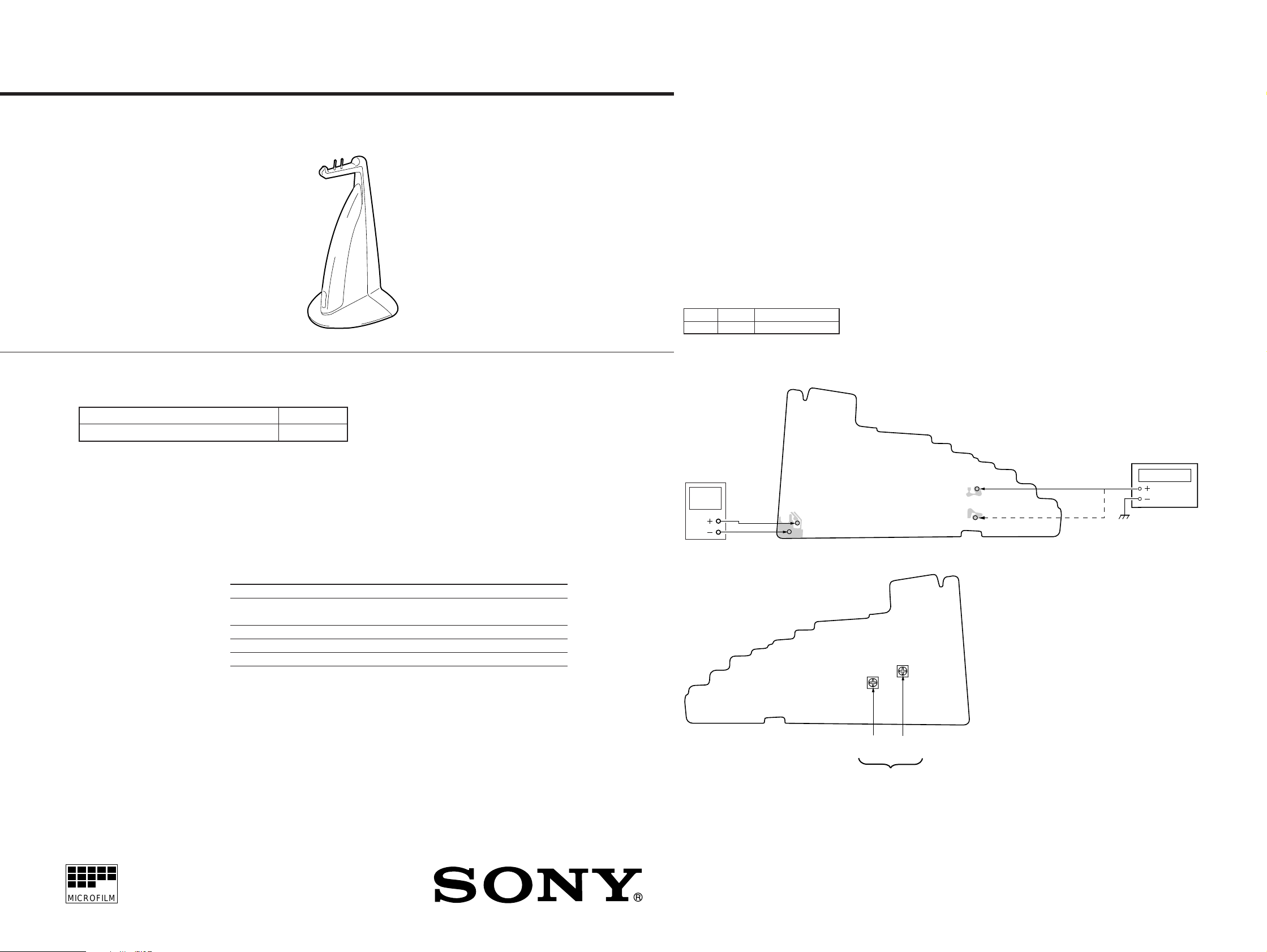
OSCILLATING FREQUENCY Adjustment
Procedure :
No signal state.
1. Connect the frequency counter to TP (CL4) (L-ch) and TP (CL-
54) (R-ch).
2. Adjust with RV1 (L-ch) and RV2 (R-ch) so that the reading on
the frequency counter becomes the specified value.
Specified Value:
L-ch RV1 2.3MHz ±2kHz
R-ch RV2 2.8MHz ±2kHz
Connection and Adjustments Location :
TMR-IF330R is the component model block one in MDR-IF330RK.
COMPONENT MODEL NAME FOR MDR-IF330RK
Cordless Stereo Headphones MDR-IF330R
Transmitter TMR-IF330R
SPECIFICATIONS
General
Modulation system Frequency modulation
Carrier frequency Right 2.8MHz
Frequency response 18 – 22,000Hz
Power source DC IN 9V jack accepts power supplied from the AC
US, Canadian,
Central & South America model
Australian model 240V AC,50Hz
E model 220 - 230V AC,50Hz
Tourist model 110 -120V/220 - 240V AC,50/60Hz
Audio input Phono jacks/stereo mini jack
Dimensions Approx. 106 x 217 x 110mm
Mass Approx. 125g (4.4oz.)
Left 2.3MHz
power adaptor for use on the following voltages:
Operating voltage
120V AC,60Hz
(4 1/4 x 8 5/8 x 4 3/8in.) (w/h/d)
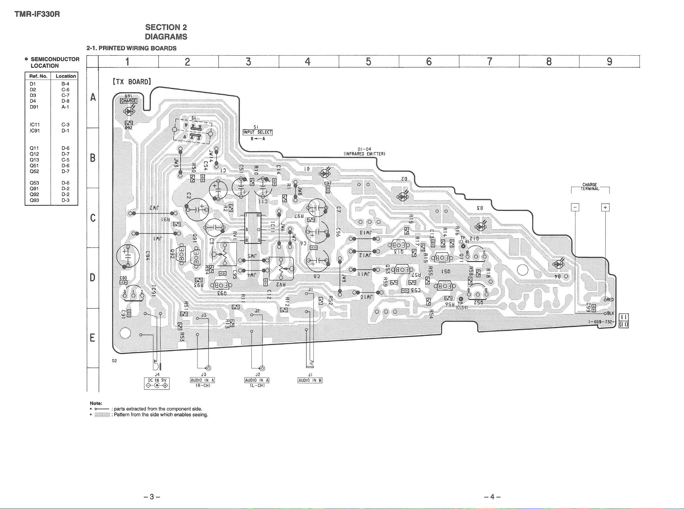
[TX BOARD] (Conductor side)
regulated dc
power suppluy
9 Vdc
[TX BOARD] (Component side)
TP
(CL4)
TP
(CL54)
frequency counter
TP(CL4)
(L-ch)
TP (CL54)
(R-ch)
MICROFILM
Design and specifications are subject to change without notice.
INFRARED TRANSMITTER
RV1
RV2
(L-ch)
(R-ch)
Oscillating frequency
adjustment
– 2 –
Page 2
Page 3

2-2. SCHEMATIC DIAGRAM
TMR-IF330R
Note:
• All capacitors are in µF unless otherwise noted. pF: µµF
50 WV or less are not indicated except for electrolytics
and tantalums.
• All resistors are in Ω and 1/
specified.
4
W or less unless otherwise
• % : indicates tolerance.
• U : B+ Line.
• H : adjustment for repair.
• Power voltage is dc 9 V and fed with regulated dc power
supply from external power voltage jack (J4).
• Voltages are dc with respect to ground under no-signal
conditions.
• V oltages are taken with a VOM (Input impedance 10 MΩ).
Voltage variations may be noted due to normal production tolerances.
• Signal path.
F : AUDIO
J : RF
– 5 – – 6 –
r
IC BLOCK DIAGRAM
IC11 TA2061AF-EL
L-CH
IN
16 15 14 13 12 11 10 9
VREF
MIX AMP
1 2 3 4 5 6 7 8
R-CH
IN
NF VREF
LEVEL
DET.
AGC
AGC
AGC
AUTO
ON/OFF
OFF T/C
O.S.M.
LEVEL
DET.
AGC T/C
VCC
PRE
EMPHASIS
Lout = L + K • (L–R)
Rout = R – K • (L–R)
PRE
EMPHASIS
GND
F0 ADJ (R)
VCO BUFFER
VCO
F0 ADJ (L)
ADJ
ON/OFF
BUFFER
ON/OFF
SURROUND
L-CH
R-CH
OUT
OUT
Page 4

SECTION 3
EXPLODED VIEW
TMR-IF330R
TX
SECTION 4
ELECTRICAL PARTS LIST
NOTE :
• -XX, -X mean standardized parts, so they
may have some difference from the original
one.
• Items marked “ * ”are not stocked since they
are seldom required for routine service. Some
delay should be anticipated when ordering
these items.
• The mechanical parts with no reference
number in the exploded views are not
supplied.
8
NOTE :
• Due to standardization, replacements in the
parts list may be different from the parts
specified in the diagrams or the components
used on the set.
• -XX, -X mean standardized parts, so they
may have some difference from the original
one.
• RESISTORS
5
5
All resistors are in ohms
METAL : Metal-film resistor
METAL OXIDE :Metal oxide-film resistor
F : nonflammable
Ref. No. Part No. Description Remark Ref. No. Part No. Description Remark
* A-4542-507-A TX BOARD, COMPLETE
******************
< CAPACITOR >
C1 1-126-163-11 ELECT 4.7uF 20% 50V
C2 1-126-786-11 ELECT 47uF 20% 16V
C3 1-126-157-11 ELECT 10uF 20% 16V
C6 1-163-031-11 CERAMIC CHIP 0.01uF 50V
C7 1-126-163-11 ELECT 4.7uF 20% 50V
C8 1-126-382-11 ELECT 100uF 20% 16V
C11 1-124-464-11 ELECT 0.22uF 20% 50V
C12 1-163-031-11 CERAMIC CHIP 0.01uF 50V
C13 1-164-161-11 CERAMIC CHIP 0.0022uF 10% 100V
C14 1-163-245-11 CERAMIC CHIP 56PF 5% 50V
• Items marked “ * ”are not stocked since they
are seldom required for routine service. Some
delay should be anticipated when ordering
these items.
• SEMICONDUCTORS
In each case, u : µ , for example :
uA.... : µ A.... , uPA.... : µ PA....
uPB.... : µ PB.... , uPC.... : µ PC....
uPD.... : µ PD....
• CAPACITORS
uF : µ F
• COILS
uH : µ H
Q13 8-729-119-78 TRANSISTOR 2SC403SP-51
Q51 8-729-119-76 TRANSISTOR 2SA1175-HFE
Q52 8-729-024-00 TRANSISTOR 2SC3377-QR
Q53 8-729-119-78 TRANSISTOR 2SC403SP-51
Q91 8-729-422-57 TRANSISTOR UN4111
Q92 8-729-422-57 TRANSISTOR UN4111
Q93 8-729-029-72 TRANSISTOR DTC114YS-TP
R1 1-216-133-00 RES,CHIP 3.3M 5% 1/10W
R2 1-216-041-00 METAL CHIP 470 5% 1/10W
R10 1-216-097-91 METAL CHIP 100K 5% 1/10W
R11 1-216-003-11 RES,CHIP 12 5% 1/10W
R12 1-216-025-91 METAL CHIP 100 5% 1/10W
When indicating parts by reference number, please include the board.
< RESISTOR >
4
1
3
6
7
2
Ref. No. Part No. Description Remark Ref. No. Part No. Description Remark
1 4-995-958-01 WINDOW, LUMINOUS
2 4-995-956-01 CABINET (FRONT)
* 3 A-4542-507-A TX BOARD, COMPLETE
4 4-995-957-01 CABINET (REAR)
5 7-685-104-19 SCREW +P 2X6 TYPE2 NON-SLIT
6 4-984-729-01 FOOT, RUBBER
7 4-995-959-01 KNOB, CHANNEL
8 X-4949-961-1 CONNECTOR (2P) ASSY
C51 1-124-464-11 ELECT 0.22uF 20% 50V
C53 1-164-161-11 CERAMIC CHIP 0.0022uF 10% 100V
C54 1-163-245-11 CERAMIC CHIP 56PF 5% 50V
C91 1-163-031-11 CERAMIC CHIP 0.01uF 50V
C93 1-163-031-11 CERAMIC CHIP 0.01uF 50V
C94 1-126-786-11 ELECT 47uF 20% 16V
C95 1-165-319-11 CERAMIC CHIP 0.1uF 50V
C96 1-126-382-11 ELECT 100uF 20% 16V
C97 1-165-319-11 CERAMIC CHIP 0.1uF 50V
C99 1-165-319-11 CERAMIC CHIP 0.1uF 50V
< DIODE >
D1 8-719-992-13 LED LIR5BE (INFRARED EMITTER)
D2 8-719-992-13 LED LIR5BE (INFRARED EMITTER)
D3 8-719-992-13 LED LIR5BE (INFRARED EMITTER)
D4 8-719-992-13 LED LIR5BE (INFRARED EMITTER)
D91 8-719-066-58 LED SM2512 (CHARGE)
< IC >
IC11 8-759-497-48 IC TA2061AF-EL
IC91 8-759-095-60 IC S-81250PG
< JACK >
J1 1-764-270-11 JACK,STEREO MINIATURE(DIA.3.5)
(AUDIO IN B)
J2 1-784-910-21 JACK, PIN (AUDIO IN A L-CH)
J3 1-784-910-11 JACK, PIN (AUDIO IN A R-CH)
J4 1-778-380-11 JACK,DC(POLARITY UNIFIED TYPE)
(DC IN 9V)
R13 1-216-024-00 METAL CHIP 91 5% 1/10W
R14 1-216-338-11 RES,CHIP 30K 1% 1/10W
R15 1-216-596-11 RES,CHIP 2.7K 1% 1/10W
R16 1-216-053-00 METAL CHIP 1.5K 5% 1/10W
R17 1-216-041-00 METAL CHIP 470 5% 1/10W
R18 1-216-003-11 RES,CHIP 12 5% 1/10W
R19 1-216-053-00 METAL CHIP 1.5K 5% 1/10W
R50 1-216-097-91 METAL CHIP 100K 5% 1/10W
R51 1-216-003-11 RES,CHIP 12 5% 1/10W
R52 1-216-025-91 METAL CHIP 100 5% 1/10W
R53 1-216-024-00 METAL CHIP 91 5% 1/10W
R54 1-216-338-11 RES,CHIP 30K 1% 1/10W
R55 1-216-596-11 RES,CHIP 2.7K 1% 1/10W
R56 1-216-053-00 METAL CHIP 1.5K 5% 1/10W
R57 1-216-041-00 METAL CHIP 470 5% 1/10W
R58 1-216-003-11 RES,CHIP 12 5% 1/10W
R59 1-216-053-00 METAL CHIP 1.5K 5% 1/10W
R91 1-216-019-00 METAL CHIP 56 5% 1/10W
R92 1-216-021-00 METAL CHIP 68 5% 1/10W
R93 1-216-057-00 METAL CHIP 2.2K 5% 1/10W
R94 1-216-073-00 METAL CHIP 10K 5% 1/10W
R97 1-216-017-11 RES,CHIP 47 5% 1/10W
< VARIABLE RESISTOR >
RV1 1-241-767-21 RES, ADJ, CARBON 100K
(OSC FREQUENCY L-CH)
RV2 1-241-767-21 RES, ADJ, CARBON 100K
(OSC FREQUENCY R-CH)
< TRANSISTOR >
Q11 8-729-119-76 TRANSISTOR 2SA1175-HFE
Q12 8-729-024-00 TRANSISTOR 2SC3377-QR
Sony Corporation
9-924-905-11
Personal A&V Products Company
– 7 – – 8 –
< SWITCH >
S1 1-554-222-00 SWITCH, SLIDE (INPUT SELECT)
98E027041-1
Printed in Singapore © 1998.5
Published by Quality Engineering Dept.
(Shibaura)
 Loading...