

Page 1
Page 2
Page 3
Page 4
Page 5
Page 6
Page 7
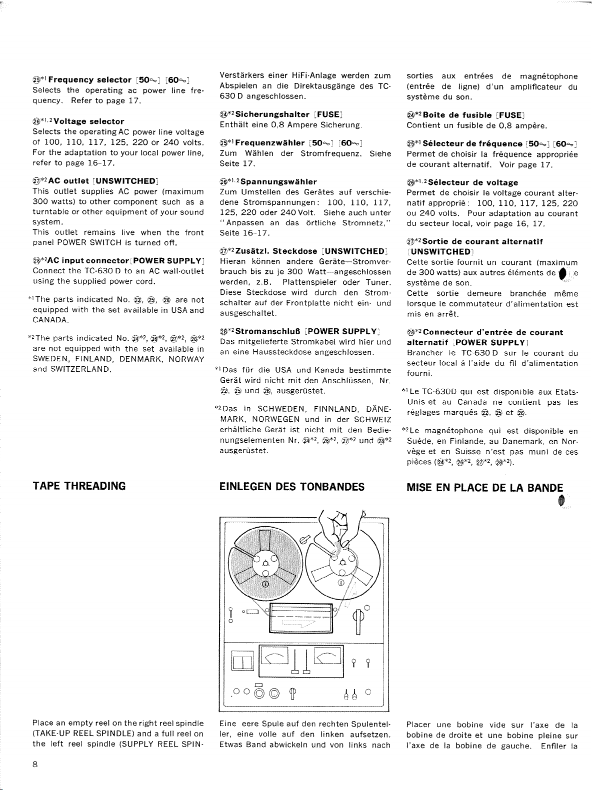
Page 8
Page 9
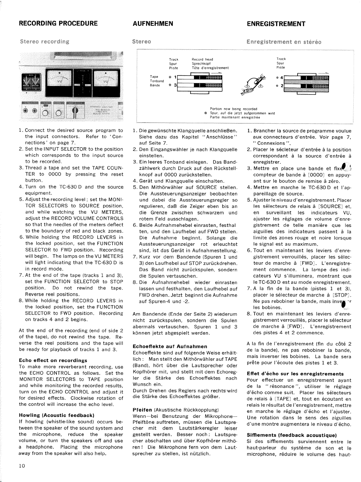
Page 10
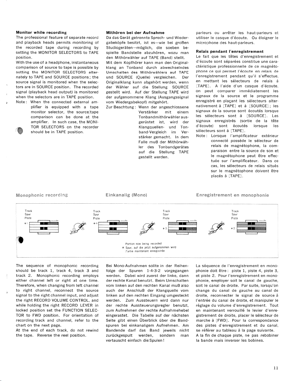
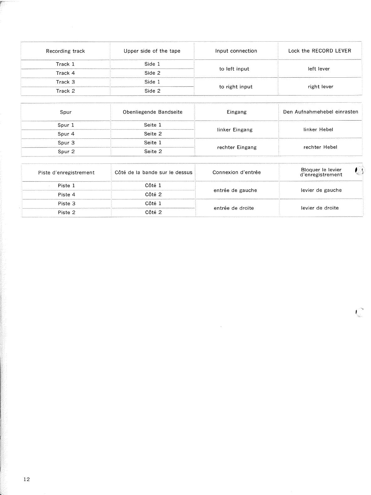
Page 11
Page 12
Page 13
Page 14
Page 15
Page 16

Page 17

Page 18

Page 19

Page 20

Page 21

Page 22

Page 23

Page 24

Page 25

Page 26

.."r.--,
.:t,_.,
,
.
..
:_:
a.
-r
Power Requirement:
Frequency
Signal-to-Noise
Recording
Harmonic
.
Tape
Speeds:
Reel Size:
Recording
System:
Response:
Flutter and
Distortion
lndication
Level
Outputs:
Recording
(with
1,800ft
Semiconductors:
Dimensions:
Weight:
Wow:
Ratio
lnPuts:
Time:
tape)
Heads:
AC
l17 volts,60 Hz,
7'z ips,
7"
4-track
2O-22,OOOHz al 7'/
20-L7,OOOHz
20-10,000
Less
Less
Less than
:
Better
:
Less
Two Vu meters
:
Low lmpedance Microphone
High
Line
Headphone Outputs
Headphone Outputs
A-track
Transistor'. 22
Diode :
Record:
Playback : PP3O-29024
Erase: EFIA'29O24
16'1
t40.8x
24
3% ips and
(18cm)
than 0.0996 at
than O.L2?6 at
than
than L.2/6
lmpedance Auxiliary
smaller
or
Stereophonic
at 3jl
at lVs
Hz
O.I6t/6
52 dB
Outputs: O
Stereophonic
hrs.
6
lbs. 15 oz.
at
(W)x7
19.9
1/i ips
3
RP30-2902
%(Hlx1811il"
x48.0
(11.3
61
dBs
(for
(for
(4.8cm/s)
pcs.
pcs.
cm)
3OW
L76
or
7%
3;l
Ili ips
(19
ips
Monophonic
(19
ips
(9.5
ips
(4.8cm/s)
ips
(19
ips
(9.5
ips
(4.8
lnputs:
lnputs:
lO.775Vl,
monitoring) : Load impedance
listening) : Load impedance
s, 9.5 cmls
cmi
cmls)
cm,/s)
cm/s)
cm/s)
cm/s)
72
dBs
22
dBs
Load impedance
4-track Monophonic
(0.06
12 hrs. at
(D)
kgs.)
ffiffi-re-rury
and
(0.19
more
L%ips
V)
4.8
mV)
8Q
cm/s)
than
100ko
8Q
(4.8cm/s)
t\
SERVICE MANUAL
Page 27

ications
Specif
Diagram
Block
General
Technical
Cabinet
Cabinet
Chassis
Chassis
Method
........
Description..
Features
..
Views
Side
Top View.....
Top View.....
Bottom
View
of Disassembling
Preventive Maintenance
Transport
Tape
Mechanical
Electrical
Diagram
Level
Diagram
Wiring
Schematic
Mounting
Playback
Mechanism
Ad.iustment......
Ad.iustment
Diagram
Diagram
Amplifier
"
Record
Amplifier
,,
Bias oscillator
Power Supply
"
Exploded
Diagram
Cabinet
Head
Control
Chassis
Top View
Deck
Chassis
Top View
Top View
the Set
.....
(Conductor
(Component
(Conductor
lcomponent
Top
Coil
View
& Trap
(Conductor
(Component
TABLE
Side)...
Side)
Side)
Side)
(Conductor
(Component
Side)
Side)
OF CONTENTS
.
..
Side).
.
Side)
Page
3.t4
10-11
13- 16
17-19
.....
20
2r
-23
24-25
26
27
2A
29
30
5U
31
31
32
??
34
35--36
1
3
3
4
5
6
7
8
9
When ordering
attached
The
herewith.
reference
replacement
number or
parts you
symbol
shauld use
number should
PART NLJMBER
for ordering
used
not be
-2
tisted on
purposes.
the
Complete
Spare
Parts List
Page 28

Circuit Outline
on-Sound
Recording
and
of Sound-
Echo-Effect
(Fig.2)
(Fig.
3)
(Fic.4)
-4-
Page 29

(
Fig.
5)
1i
Page 30

-6-
(Fie.
6)
Page 31

-7-
Page 32

Removal
of
@-tou""
Knobs
n"oo
&
Head
Cover
:9€i Ornomenlol
Scres
Removal
oRF3x8
Reel & Control
of
scres
EPCS
Panels
Y
Y
ornom€nror
lgi'
' aPcs
wosher
xnou.
fi)
\
sOS control
-/
xnor.
/i"X
\:/ inpul
*!1
'(i\
s€lcctor
dX rnou,
!]Y
6!A x.oo.
slrde
\:7
xnor.
ecnoconlrot
nonilor
volume
sclcctor
coilrol
@
Knob.
noiSc
@
Removal
suPpresg
of
@ **0.
;;uer
sritGh
(
Fis. 8)
Chassis
switoh
_
z.riiL_/z
--6-\D<)l
\<.[n
g
(
Fig.
I
e
g
10)
E
1
E
g
jP Wosher,
e
l:
E
^E^
cdbrner
g
-8-
Page 33

The
year,
following
whichever
parts
occurs first.
1. Motor
Motor requires
2. Gapstan
Capstan
requires
3. Pinch Roller
Pinch Roller requires
ldler
4.
ldlers require lubrication
lf the oil
should spill on the
of the tape transport
Lubrication
drops
of SONY
of SONY
4
or 5
2 or 3 drops
2 or 3 drops
if they
only
rubber
mechanism
of importance
is
(light
Oil
Oil
of SONY
become
or the belt,
wheel
require
machine oil).
(light
machine
(light
Oil
noisy.
lubrication
to insure
oil)'
machine
no
Use
wipe
proper
oil).
more
it off
two
after
operation
one drop
than
immediately
thousand
of the
SONY
of
with alcohol.
of
hours
equipment.
(light
Oil
operation
machine
or
oil)'
once a
The
This
flutter
following
cleaning
wow, or
and
parts
Capstan
Pinch
Flywheel
ldler
Tape Guides
Heads
must
Roller
be
is of importance
poor
frequency
cleaned
forthe tape
response.
with a
liniless
threading
cloth
path to
moistened
with alcohol
prevent a loss
of
(methyl)
positive
optimum
for
drive at
performance'
capstan, drop-outs,
(Fie.
o_
11)
(
Fig.
12)
Page 34

Supply
Reel
Table
rn
SlriP r:-rode
REWIND
ldler
REWIND Belt
Motor Pulley
Take
up Reel Table
T ake-up
'
ldler
ON/OFF
B'ias
(OFF
Supply
Ree I
Table\,..
Lever
0N/oFF Switch
Bla\
(ON
Switch
Position)
Position)
FCRWARII
I
RFWiND
mocle
ldler
REWIND
Motor
f,
Belt
Pulley
Fu nc t
Selector
Cam
ior,
a
T
ke-up
Reel
Table
I aKe-up
ldler
Bras
ONr'OFF
(OFF
Switch
Position)
rn
Capstan
FEr!lND
REWIND
REWIND
){
-10-
mode
ldler
Motor
Belt
PulleY
ake'uP
T
Reel
T
Table
ake-uP
Page 35

at
7y2ips
(19cm/s)
R
-l
speed
EWIN D
*.
;
''
Motor
r\f
Take up ldler
Pul
ey
FAST
FORWARD
Crank
t'
Button
(
Fig.
16)
Se
Speed
lec
to r
Leve r
Motor
Pulley
I
Iake-up
I
Capstan
(
F ig, 17)
ldler
ldler
Speed Selector
Lever
Speed
aI Itiips
Se ector
$haft
(4
Bcm/s)
Motor
Pulley
+
0apstan
speed
6
ldler
Take
up
ldler
Speedj
Selector
Speed Se
ector
Lever
al 3)4ips
(9
5cm/s)
5pss6
#
Capstan
(
Take
ldler
Fig. 19)
-
up ldler
11
-
(Fig.
i8)
Page 36

(
ig. 20)
F
(r/64")
0.2-0.4 mm
in FAST
just
Ad
FORWARD
bending up or down
by
(Side
13
-
mode
View)
-
with
pliers,
(Fie.22)
in STOP
Adjust by bending
mode at
(Top
with
View)
the
pliers.
speed of
4.
Page 37

iir-i;,ir
Pinch Roller Shaft
143/64+O.OO8ol
L7.2+O.2mm
Pinch Roller
& Down Cam
Up
.--
i
(Front
When
i
.
Adjust
moving up or down as shown
adjusting
by bending
Pinch
with
Roller
View)
roughly
pliers
& Down Cam
Up
'a
Head
Do not make scratch.
When adjusting accurately
'
Adjust to oblain
below.
by
Shaft
After
Deck
t7.2+O.2mm
loosening Screw
trp
or down.
fastening
Screw, apply
and
143/64+O.OOBtl
moving
Lock Paint.
Down Cam
!l i
l$
speed
r
rf
S,
Capstan
..:.1
..:
4.8 cm/s
of
ldler Arm
(17l8
ips)
lL/64-5/64'l
O.5-2 mm
(
23)
Fig.
(Bottom
Rewind
View)
Lever
Z
-14-
(Top
'
supply
View)
lf
belt does
bending
by
Reel Table
(
21)
Fig.
not run
smoothly,
up or down with
Rewind
ldler
(Fie.24)
adjust
pliers.
Page 38

r;;:cir
,
irl;iiioi:
in FORWARD
Acijus;;;:ent
mode
mm 11,/64n1
0.5
F
in
Adjusting Plate
!i'l::tant
FORWARD
lnstant
Stop
stop
mode withor
Lever
Lr
in FORWARD
pstan
Ca
just
Ad
by bending
ldler inclines when Flywheel
ldler
lf
slips, clean the surface
or down
up
alcohor
*S
STOP mode at the
tn
the
adjust
(Top
Viewl
i,i"1.,:!.ii-i
mode at
with
is
f inger-stopped.
iiliti
the speed of
pliers
in
of ldler
(Side
.- i'i-l: li.1l
idier F-r;!iii;ir
'
speed
position
:-,.,-,
case
with
of Head Deck.
l,.irp:i.i
4.8
Motor
View)
19cm/s
of
cm/s
Pulley
(7t
(
F ig.
(17le
(Fig.
zipsl
25t
28)
ips)
I/64-L/3241
Motor
H
I
i+e
O.5.*1.Ofiffi
iake-ui:
in FAST
Pulley
,1l.j:iJ;)-i
.;i;;.:
il
Pinch []
(ToP
iilier
nojt
this4,
(Side
Vievi
i!r,;t-lFF SW-
Switchu
r\
3
tr
N
t=
L.
k\
=l
to be flush
to be adjusted by finger-pushing
(Side
View)
-15--
up
or
down
(
Fig.31)
View
Side
Loosen Screws and adjust by slidin6
Page 39

Acjjl,.r.,t i''r
l\ier
airt
rt capstan sleeve attached
'
Loosen
position
the
Screw and
adjust
of Adjusting
Plate.
1r-
@l*1
lt=
#---=-
/iew)
Adjusi-.i,;r;
iD
mode
Table
>l
(Fig.26)
tn
Loosen Screw
i:
:-,
4+
in FORWARD
5:1,:.
FORWARD ffiod€
Screw
-,*i.t.i
shown and
(Top
-;;:;
i-,1r;,
mode
rake-uptdter
i'a;,t;,iil,.
corruct the
adjust by sliding
Aii;:.t .'.t"''tnr
t
position
Switch
of
Stider's end
Slider
Holder.
View) (Fic.27)
the
at
Take-up
speed of
Reel Table
4.Bcm/s
|-l
/nh
(17l8
-
in
ips)
ust by bending
;
crank up
v)
i(:
Off
T'I
Micro Switch
:
h
''l:
position
A ct uator
or
:..
:.'i
down with
j';
l-'
i
.l
i
Holder.
pliers
(Fie.29)
(Fig.32)
Loosen Sirews
/
take.up
so that
.*
dd
s ttr
shown,
Erase Head
mode,
there should
fast forward mode, tape should
ln
screw
and adjust
Pad
Hinge
lL,/64-L/32'l
ln forward
as
Make the adjustment
Loosen the
adjust
and
idler makes
(Side
'
...,':
-
in FORWARD
be the
with
sleeve
1Omm
Shifter
attached to
by
the
contact
View)
positioning
with the
mode
clearance of 0.5-1.0 mm
capstan and without sleeve.
0.5
-
11. /64-r /32',1
pulley
not contact with heads.
shifter.
of Motor
height
Pulley
shown'
as
lL/64-L/32'l
(
Fig.30)
-16-*
Page 40

ffi
l
Playback Head
Alignment
2. Playback
Level Adjustments
3. Playback
justment
Ad
7
lIl
).4
(2\
3i+
ips
4. Bias Trap
Head
Record
5.
Azimuth Alignment
&
Item
Level
Equalizer
(19
ips
(9.5
Coil
Height,Zenith
Azimuth
Meter
and
cm/s)
cm.s)
Adjustment
10kHz,
ment Tape,
1 kHz, 1st
ment Tape,
SONY
3rd
.
Monitor
Monitor
Alignment
Monitor
Alignment
SONY
Monitor
1 kHz,
6O
lnput
Signal
Source
section of
J-19-F2
Switch :
section of
J-I9-F2
Switch : TAPE
Tape,
Switch:
Tape, J-9.F1
Switch:
(0.78
dBs
Selector:
mV)
SONY
TAPE
SONY
J.I9.F2
TAPE
TAPE
MIC Jack
to
MIC
Align-
Align-
Output
VTVM and 100 kO
parallel
VTVM
parallel
VTVM and 10O
parallel
VTVM
VTVM and 100 k
parallel
to
and
to LINE OUT Jack
to
to Test Point
(See
to LINE
LINE
100 kO
LINE
Page 28,
Connection
OUT Jack
k
Q
OUT Jack
O
OUT Jack
Resistor in
Resistor in
Resistor in
and Ground
TP.l
Resistor
in
Mode
PLAYBACK
PLAYBACK
PLAYBACK
RECORD
RECORD
6. Record Head
Alignment
Azimuth
7. Record Bias Adjustment
Record
8.
9.
Dummy
1O.
.l.l're:;-
1) Before
2l The
3l The
4l
After
Level Adjustment
Record
Equali:er
justment
Ad
Coil
.
adjustments,
Sound-on.Sound
adjustments
adjustments,
Adjustment
should be made
and
clean
(SOS)
Switch
Lock Paint to the
apply
15
kHz,
J
ack
1 kHz,
lnput
-60
90 dBs
dBs
lnput
1 kHz,
Jack
60 dBs
-
lnput
k, 20 kHz,-90
I
Jack
lnput
demagnetize the Record Head, the
and the Noise
in numerical
adjusted
l24.5ttY)
Selector:
(0.78
mV) to MIC Jacl
Selector;
{0.78
Selector
dBs
{24.5.,rV)
Selector:
Suppressor
order.
points.
to MIC
MIC
MIC
mV) to MIC
: MIC
to MIC
MiC
Switch should
VTVM
parallel
VTVM
parallel
VTVM
parallel
VTVM
parallel
VTVM to Test Point
Playback
Head and the Erase Head.
be set
10O
and
to LINE
and
to LINE
and 10O
to
and 100 k
to LINE
{See
LINE
in
100
Page
OFF
OUT Jack
OUT
OUT
OUT
position.
k
O
k
O
Jack
k
O
Jack
Q
Jack
28, TP.)
Resistor
Resistor
Resistor in
Resistor
in
RECORD
in
RECORD
RECORD
in
RECORD
RECORD
-17
Page 41

Adjust
Procedures
and
Remarks
Playback Head Azimuth Alignment
Screw
L-CH: Rree
R'r, Rzss
See
R-CH:
See
Fig.
Fig.
35.
R266
37.
(2OkO
(5
kO
;
;
L"CH: Rroz R-CH: Rzo:
(B)
2 ko
Fig.
See
37.
L-CH: Rror R-CH : Rru,
(B)
3 ko
Fig. 37.
See
Fig.
See
Fig.
See
Fig.
See
R-CH :
Fig. 34
See
R.CH: R,,,,,
(Bl
See Fig.
R-CH
: Lrut
34,
35.
35.
Crnr
34
1,,,,
Zenith
-
Alignment
and
L-CH: Lror R-CH
l.8 mH
Record Head Height,
Azimuth Alignment Screws
Record
Screw
L.CH Crn,
L-CH:
L.CH : L,,,,
Head Azimuth
"'
3O
2O0pF
Rr:,,
ko
5
1.8/1 45 mH
Fig
CH
rtg
34
L,
34
See
L-CH: L,,,, R
1mH
I
see
Adjust the screw
B)
1.
B)
Adjust
2. Adjust Rrss
Deviation against the
Tape Section
After the adjustment,
Deviation
1.
Set source
2. Adiust to
1. Turn the
visually
2.
Set MONITOR
3. Turn'Height
tu
4.
Turn
alignment
5. Repeat Steps
L
Set
2. Turn Azimuth
screw,
1.
Set
2. Turn the
Recording
3.
VTVM
4.
Continue
reading.
Adjust
5.
Make sure
6.
7.
lf
1.
Set
2.
Feeding
o vu
Record
3.
4. Set
Ad.iust
5.
Set
Record
Record
the
Note: Two
1
Set
2.
Read the
Set
4.
Adjust
5.
Set
to obtain
(L-CH)
Rroo
(L-CH)
Frequency
L.CH
R-CH 3.512 dts LOi2
against
Tape Section
uency
Freq
L-CH
R.CH
rns.
Zenith
MONITOR
MONITOR
the
volume
obtain
screws
three
horizontal.
switch to
Alignment
Alignment
screws.
2 and 3 until
switch to
Alignment Screw
maximum reading
the
switch to
trimmer
signal, turn the
the
reads the
turn the capacitor
to
Read the VTVM
trimmer capacitor
the
that
reading of
not, repeat Steps
MONITOR switches
the
the
the
same as
source volume
the
the
stgnal, slide
the
1700%1.
signal on a blank
the
MONITOR switches
Rr:'
{R:zn)
MONITOR switches
1 kHz signal of
kHz
20
one of 1 kHz signal.
peaks
in
shown
VTVM
machine
L,"' so that
rirachine
maximum
and R,us
and Rzar
level
4th 3rd 5th
12.5
kHz
otZ dB
repeat
the
level
of 500
4th 5th
kHz
5
0+2 dB oa2
controls
minimum
(height,
TAPE.
Screw
and
TAPE
TAPE
capacitors counter.clockwise
maximum value.
reading.
2-6 again.
the source
so that
signal of
Fig.
rcadings of
in
in R.CH RECORD
VTVM indicates
90 dBs
-
-90
appear during
36.
controls
L-CH RECORD
VTVM reading is
reading
(R-CH)
(R-CH)
1 kHz oI 2nd
of
10 kHz
ot2 dB
on VtVfrl.
to obtain
so that
0 dBs
pointers
section
7 kHz IOO Hz f,U HZ
ot2 dB
Meter Level Adjustment.
3rd
Hz of
3 kHz 2OOHz IOO Hz
dB
(Rr3r
& Rz33)
reading
zenith and
obtain
to
Azimuth
maximum
position.
to
should
position.
trimmer
until
{Cr,,,,,
is the same as
L'CH
&
{S,,,0
tape.
(Sr,'r
&
($1u,
&
124.51,Y)
Ort
turning Lr,i
(Rrj3
&
channels.
both
section
6th 7th
2i2 dB
25L2dB
minimum
to
VTVM.
on
aziml'th
maximum reading on VTVM. Memorize
Alignment
reading is
obtain
obtained. lf not, repeat the
be
Screws
maximum reading on VTVM.
and
capacitor
the VTVM reads a value 0.5 dB below
R
in
CH)
to
S,u'l
volume
to
S,u,')
to
S,',;)
,r4.51tY)
Rr.,,) to minimum.
mode.
the
same as one
mode
and adjust L,,
same
the
one read
SOURCE
controls
TAPE
O
dBs
{0
TAPE
blank tape and
on a
and adjust
1L:,
(0.775V)
Level Mcters
of
6th
3.Or2 dB 2.O!2dB
(J.542
dts
I.Oa2 dB
alignment) so
the same number
obtained
set them in minimum
(C:',,i,,
L-CH)
way.
in
position.
(Rrsr
& Rz::)
position
775V)
position.
Lror
Take
L).
the
read in
in the same way
,
on VTVM.
stay
at 0 VU
7th
dts
that Record Head will be
the number of
of
turns
Within one turn of the
adjustment as
capacitance
clockwise slowly until the
in
the
4
Step
level meters
so that
read
(Lzor)
peak
Step
VTVM reading
the
so that VTVM
where
the core is
2.
(1OO%).
of height
ltem
5.
position.
maximum
indicate
reading
"
is
"
b
Bias
Voltages
Erase Voltage applied
applied
to Rec, Head
Erase
to
Head
are
approximately (
is approximately
1A
16
(
14
\ rz
120
Votts
Volts
vort.
Volts.
al 7/
ips
at 3V|ips
at L/i
ips
(19
(9.5
(4.8
cm,
sl
cm,s)
cmi
\
.
f
/
s)
Page 42

(
Fig.
34)
(
Fig.
35)
Lror,
zor
Circuit Boord
(Fig.36)
I
Fis 37)
Page 43

CEt
tuP
CM
t00P
Cn
tuP
I.CH ft
HEAD
iL-cH
pd
ix-i-ec
nntUK
Otos Qto.
2SO6E'
2SC65t
AMp
eoaRD
@
0uk)
Stot'e
6m
30s
R-L
qilLt
7+
J]K
L.R
)
VR
PHat
PPno-2t02
fr.CH
P8
A
HEAD
R-CH
I
fraE IMK
Rtu
Otor
2SC6!r'
REC
/00K
Oror
250631
AMP
/6)
U/
Qco+
25C6:t3
-24-
lat-t
1m-e
Page 44

orr2SOS!{
LJOI
L-
1pr,'
E nnlily
Sare
o
ffi
Te
edlAN
Orc2!tC63{
erAs osC-eoARo
fiHt-t
Sprt
Schematic
1.
2
2.
fi
All
3.
pF
Resistor
4.
letter
The
5.
of
5. Voltage
VTVM
speed
noted
Voltage
Notes:
: Adjustable
: Grounding
resistors
respectively
whose
(N)
is
letter
potentiometer indicates
values
in PLAYBACK
7'/z ips
of
because
values
parentheses.
in
14
fl EnaE
tn 0. R4fl
EH20t
-290e4
ER|SE tuq
to Chassis
and capacitors
unless
rating
low-noise
(C)
(Bl
(A),
or
measured
are
and
(19
cm/s).
normal
of
RECORD
in
SUPruY
BOARD
rated
are
otherwise
value
resistor'
suff
specified.
is suffixed
to
ixed
characteristic'
its
ground
to
RECORD
production telerance'
mode at
Variations
are
mode
in
with the
rating
enclosed
Q
value
with
may
METER
PLW
METER
PLfi'
PLlil NWER
and
a
the
be
UMP
LAIIP
UMP
(L-CH)
(fr.CH)
Record/PlaYback
Selector
lnput
&
Speed
Monitor
Muting
Noise Suppress
Sound-On-Sound
Sound-On-Sound
Switch
Bias Switch
Power Switch
Auto-Shut-Off
fl
HI
I
il7v
A.C.
60llz
Equalizer
Switch
Switch
Switch
Switch
Switch
Switch
Switch
Selector
Switch
7%r
lI9
cm/sl
(\
o
c
E
I
(
(
{
I
o
-25-
Page 45

I
I
I
-\
o?
d
@
r
@
Cabinet
.49
Top
View
-
v
Plain
Spring Washer
SW:
Lock Washer
Nut
Retaining
E:
\
/*t
Washer
Ring
Number
1
Reference No.
listed in
List
Parts
i!"t
encircled
the Complete
shows
which
attached
€9
is
Spare
hereto.
..<
g
a
y
Y
aAr)
\
;
I
\
-'i4
-:a
Y
I
t ._
Page 46

/6\
5
F
,?'
lol \di
\;/v
/-::\
@
-:
It
3
(D
o-
o
a
U)
a
(E
-c
c)
-
A\
,/
\r\
,,
'''i...
. i\ /e,
is)
/a\
to_
,g€)
-1
-€,
*
a),O:'E
Y
dd
--
,ub,
' (|.)
35
--
tD\ \
J\0
980667 - I
Page 47

,'i',
j
%
,e..
-+,'
I t'r
'
-4,'
I
'
'
-/l
Cx.
'\t
r\
v
{\l
l
v
(.i
6-}
€bo
=
ah0
/Cl
\S/
,/iir
\cO
@o-o
q
@:
@-=
i_
rLi
P?-
f
rc
li'l-'_l
\,:/
\=/
-s
I
O
N
2.
\='
€.
--
--ie)
'\{-/
! .o @ 9.'5
O-!!.-^
ElES-9
oi
b;n(
c=oE-
o;
ooi
-
v
-</
"
:g?*E;
;eir€€
EE;;37
Eggt
&.
2
:I
rb0
-9-
9;9
3;3 v
3
*3
c.E:<
#,4!;p
v
f
or
i
.E
E
'6
=
o:
k
980667
=giz-
SONY
- 1
CORPORAT
,-
36
--
ION
Printed
in Jopon
Page 48

;
\'l
i,l't
:1!l,.--,.]
,A-
i.
-2-
G+t
Head
Deck
r_^\
qj
,,'ta\
'19
Top
t?F.,,. =,
,
isq
1>-
,l
.43
zii
I
,to
View
)
T
+(.)
.-/'''
.,/
t 12
PF).
,J
.
Y
v
v
l.li
:_,,---\
:.-
i
e,
g
il
e"
&--
,v
Plain Washer
Washer
Spring
Washer
Lock
Nut
Retaining
Ring
Number
Relerence
listed in the
Parts List attached
encircled
which
No-
ComPlete
shows
is
SPare
hereto.
Page 49

Control
Chassis
Top
View
--l
f)):,
,'-,
f
-s,r,
{
Q'-*-
-r:;\'
,6C
,oi)
(1*
,'@
8g
Frl
':
"'-/
6,/
1',8?-
e#-
B
@lr
@
\/
,/
t'i'
3v.'
L\}Y
l.
I
Piain
:
Spring
Lock
Nut
Retaining
oq
OP
,w
CIP'
CIe
Washer
Washer
Washer
Ring
34
e
0
g
a.O
%
Oo
-v
v
-_l
v
i
:
;
1
dl
U
I
I
t
 Loading...