

Sony SVTRA-168 Service manual

TIME LAPSE VIDEOCASSETTE RECORDER
SVT-RA40
SVT-RA168
COMPUTER INTRFACE BOARD
SVT-RS100
SERVICE MANUAL
1st Edition

! W ARNING
This manual is intended for qualified service personnel only.
To reduce the risk of electric shock, fire or injury, do not perform any servicing other than that
contained in the operating instructions unless you are qualified to do so. Refer all servicing to
qualified service personnel.
! WARNUNG
Die Anleitung ist nur für qualifiziertes Fachpersonal bestimmt.
Alle Wartungsarbeiten dürfen nur von qualifiziertem Fachpersonal ausgeführt werden. Um die
Gefahr eines elektrischen Schlages, Feuergefahr und Verletzungen zu vermeiden, sind bei
Wartungsarbeiten strikt die Angaben in der Anleitung zu befolgen. Andere als die angegeben
Wartungsarbeiten dürfen nur von Personen ausgeführt werden, die eine spezielle Befähigung
dazu besitzen.
! AVERTISSEMENT
Ce manual est destiné uniquement aux personnes compétentes en charge de l’entretien. Afin
de réduire les risques de décharge électrique, d’incendie ou de blessure n’effectuer que les
réparations indiquées dans le mode d’emploi à moins d’être qualifié pour en effectuer d’autres.
Pour toute réparation faire appel à une personne compétente uniquement.
SVT-RA40/RA168

CAUTION
ADVARSEL
Danger of explosion if battery is incorrectly replaced.
Replace only with the same or equivalent type
recommended by the manufacturer.
Dispose of used batteries according to the
manufacturer’s instructions.
Vorsicht!
Explosionsgefahr bei unsachgemäßem Austausch
der Batterie.
Ersatz nur durch denselben oder einen vom
Hersteller empfohlenen ähnlichen T yp . Entsorgung
gebrauchter Batterien nach Angaben des
Herstellers.
ATTENTION
Il y a danger d’explosion s’il y a remplacement
incorrect de la batterie.
Remplacer uniquement avec une batterie du même
type ou d’un type équivalent recommandé par le
constructeur.
Mettre au rebut les batteries usagées conformément
aux instructions du fabricant.
Lithiumbatteri - Eksplosjonsfare.
Ved utskifting benyttes kun batteri som
anbefalt av apparatfabrikanten.
Brukt batteri returneres
apparatleverandøren.
VARNING
Explosionsfara vid felaktigt batteribyte.
Använd samma batterityp eller en likvärdig typ
som rekommenderas av apparattillverkaren.
Kassera använt batteri enligt gällande
föreskrifter.
VAROITUS
Paristo voi räjähtää jos se on virheellisesti
asennettu.
Vaihda paristo ainoastaan laitevalmistajan
suosittelemaan tyyppiin.
Hävitä käytetty paristo valmistajan ohjeiden
mukaisesti.
Lithiumbatteri-Eksplosionsfare ved fejlagtig
Levér det brugte batteri tilbage til leverandøren.
SVT-RA40/RA168
ADVARSEL!
håndtering.
Udskiftning må kun ske med batteri
af samme fabrikat og type.
1 (P)


Table of Contents
Manual Structure
Purpose of this manual .............................................................................................. 5
Related manuals......................................................................................................... 5
Contents ..................................................................................................................... 6
1. Service Overview
1-1. Maintenance Table on the Monitor Screen .................................................1-1
1-2. Removal of Cabinet, Mechanism Unit, and Main Board............................1-3
1-2-1. Removing the Cabinet Parts....................................................... 1-3
1-2-2. Removing the Mechanism Main Unit and
the CP-1 PWB Assembly ...........................................................1-4
1-3. Temporarily Setting Up and Connecting CP-1 PWB Assembly ................1-5
1-4. Installation of the Front Panel .....................................................................1-5
1-5. Circuit Board Locations ..............................................................................1-6
1-6. Lithium Battery for Backup ........................................................................1-6
2. Mechanical Adjustments
1. Maintaining and Checking the Mechanism .................................................... 2-1
1-1. Regular Checks and Maintenance Items .............................................2-1
1-1-1. Regular Checks ..........................................................................2-2
1-2. Service Tools and Cleaning ................................................................ 2-3
1-2-1. Service Tools..............................................................................2-3
1-2-2. Cleaning .....................................................................................2-4
2. An Overview of the Mechanism.....................................................................2-5
2-1. Names of the Main Parts .....................................................................2-5
2-1-1. Cassette Mechanism Assembly.................................................. 2-5
2-1-2. Topview......................................................................................2-6
2-1-3. Underside ...................................................................................2-7
2-2. An Overview of the Mechanism Modes ............................................. 2-8
2-2-1. Mechanism Mode Switching Table ...........................................2-8
2-2-2. Movement Check List for the Main Parts of the Mechanism ....2-9
2-2-3. How To Check The Mechanism Mode Position ........................2-9
2-2-4. Self-diagnosis Display ...............................................................2-9
3. Disassembling the Main Parts of the Mechanism......................................... 2-10
3-1. How to Make the Mechanism Move .................................................2-10
3-1-1. Operating the Loading Motor by the Manual Method .............2-10
3-1-2. Making the Mechanism Move Using the Manual Method ......2-11
3-2. Mechanism Unit ................................................................................2-11
SVT-RA40/RA168
1

3-3. Cassette Drive Mechanism ................................................................2-12
3-3-1. Cassette Mechanism Assembly................................................ 2-12
3-3-2. Cassette Drive Gear..................................................................2-12
3-3-3. Door Opener, Under Frame and Stand L ................................. 2-13
3-3-4. Start Rack Gear and Front Rack Gear...................................... 2-13
3-4. Cleaner Roller Assembly ..................................................................2-14
3-5. Cylinder (Drum) ................................................................................2-15
3-5-1. Cylinder (Drum) Motor, Upper Cylinder Assembly................ 2-15
3-5-2. Cylinder Mounting ...................................................................2-16
3-6. FE Head and ACE Head ................................................................... 2-17
3-6-1. Audio R/P Head Assembly (ACE Head) ................................. 2-17
3-6-2. Full Erase Head ........................................................................2-17
3-7. Capstan Motor ...................................................................................2-18
3-7-1. Capstan Motor ..........................................................................2-18
3-7-2. Capstan Brake Assembly .........................................................2-19
3-8. Loading Motor Assembly and Worm Gear Assembly...................... 2-19
3-9. Pinch Roller Pressur Mechanism ......................................................2-20
3-9-1. Pinch Roller Lever Assembly ..................................................2-20
3-9-2. Pinch Lift Cam and Pinch Cam Gear .......................................2-21
3-10. L Guide Act Lever Assembly, Load Lever Assembly and
Stopper Lever Assembly ...................................................................2-22
3-11. BT Lever Assembly ..........................................................................2-22
3-12. Reel Drive Mechanism...................................................................... 2-23
3-12-1. Reel Belt, Reel Pulley, Friction Gear Assembly and
Clutch Change Lever................................................................2-23
3-12-2. Clutch Mounting Assembly .....................................................2-23
3-12-3. S Soft Lever, Supply Reel Assembly and S Reel Gear............ 2-24
3-12-4. T Soft Brake Assembly, Take Up Reel Assembly,
T Reel Gear ..............................................................................2-24
3-13. Brakes................................................................................................ 2-25
3-13-1. S Brake Assembly, T Brake Assembly, T Brake Act Slide .....2-25
3-13-2. Brake Control Lever and Brake Act Lever Assembly ............. 2-25
3-13-3. S Brake Act Slide and BT Spring Lever Assembly .................2-26
3-14. Guides ............................................................................................... 2-27
3-14-1. Guide Roller Assembly ............................................................2-27
3-14-2. S and T Incline Mounting Assemblies .....................................2-27
3-15. Wheel Gear 2, Main Cam and OPT Pinch Relay Gear .....................2-28
3-16. Crescent Slide....................................................................................2-29
3-17. S Load Gear, T Load Gear, S Load Lever Assembly and
T Load Lever Assembly ....................................................................2-30
3-18. Tape Sensors, Reel Sensor and EP SW Lever .................................. 2-31
3-18-1. Tape Top Sensor and Tape End Sensor ...................................2-31
3-18-2. Reel Sensor...............................................................................2-31
3-18-3. EP Switch Lever.......................................................................2-32
2
SVT-RA40/RA168

4. Mechanism Checks and Adjustments...........................................................2-33
4-1. Reel Table Torque Check..................................................................2-33
4-2. Adjusting the BT Lever Assembly Position and
Checking the Back Tension Torque in Play Mode ........................... 2-34
4-2-1. BT Lever Pole Position Adjustment ........................................2-34
4-2-2. Checking the Back Tension Torque Play Mode ......................2-34
4-3. Tape Path Adjustment .......................................................................2-34
4-3-1. Adjustment Procedure ..............................................................2-35
4-3-2. Load Lever Assembly Height Adjustment...............................2-35
4-3-3. Guide Roller Height Adjustment .............................................2-36
4-3-4. Audio R/P Head (ACE Head) Height Adjustment,
Azimuth Adjustment and Horizontal Position Adjustment .....2-37
4-3-5. Checking After Adjustment .....................................................2-38
5. Test Points for Tape Path Adjustment..........................................................2-38
3. Electrical Adjustments
3-1. Servo Circuit Adjustment............................................................................3-1
3-1-1. Test Equipment and Standards Required ...................................3-1
3-1-2. Location Of Adjustment Points..................................................3-1
3-1-3. Switching Position Adj. .............................................................3-2
3-1-4. 24 H Play Tracking Confirm and Adj. .......................................3-2
3-1-5. F. Slow Tracking Confirm and Adj............................................3-3
3-2. Video Circuit Adjustment ...........................................................................3-4
3-2-1. Test Equipment and Standards Required ...................................3-4
3-2-2. Comb Filter Adj. ........................................................................3-4
3-2-3. 2 H Delay Level Adj. ................................................................. 3-4
SVT-RA40/RA168
4. Spare Parts
4-1. Notes on Repair Parts..................................................................................4-1
4-2. Exploded Views ..........................................................................................4-2
4-3. Electrical Parts List .....................................................................................4-9
5. Semiconductors
3

6. Block Diagrams
Overall Wiring ............................................................................................ 6-1
Mechanism Connection............................................................................... 6-2
Audio Circuit............................................................................................... 6-3
Video Circuit ...............................................................................................6-4
System Control & Servo Circuit .................................................................6-5
7. Schematic Diagrams
CT-1 Board (Option Board for SVT-RS100)..............................................7-1
IC002 Interface MPU Pin Function Table ..................................................7-1
CP-1 Board (VA-A) .................................................................................... 7-2
Video Circuit Waveforms ...........................................................................7-4
IC301 System Control, Timer, OSC & Servo MPU Pin Function Table ... 7-4
CP-1 Board (SY-A) .....................................................................................7-5
Servo Circuit Waveforms............................................................................ 7-6
Display (FLD) Grid/Anode Assignment Drawing & Table........................ 7-6
TM-1, TM-2 Board .....................................................................................7-7
PW-1 Board................................................................................................. 7-8
8. Board Layouts
CP-1 Board ..................................................................................................8-1
TM-1 Board................................................................................................. 8-2
TM-2 Board................................................................................................. 8-2
CT-1 Board (Option Board for SVT-RS100)..............................................8-2
PW-1 Board................................................................................................. 8-3
4
SVT-RA40/RA168

Purpose of this manual
Related manuals
Manual Structure
This manual is the Service Manual for the time lapse videocassette recorder
SVT-RA40/RA168 and the option board Computer Interface Board SVT-RS100.
This service manual provides the information of maintenance and detailed service
(parts replacement, guideline for adjustment, schematic diagrams, board layouts,
detailed parts list).
In addition to this Service Manual, the following manuals are provided.
..
. Operating Instructions
..
SVT-RA40 (Supplied with Model SVT-RA40)
Part number: 3-206-678-XX
SVT-RA168 (Supplied with Model SVT-RA168)
Part number: 3-206-574-XX
SVT-RS100 (Supplied with Model SVT-RS100)
Part number: 3-206-934-XX
SVT-RA40/RA168
5

Contents
This service manual is organized by following sections.
Section 1 Service Overview
Describes the information that is required to service (maintenance table on the
monitor screen, removal of cabinet, mechanism unit and main board, circuit board
locations, etc.).
Section 2 Mechanical Adjustments
Describes the recommended periodic maintenance, the cleaning procedure, service
tools, disassembling the main parts of the mechanism and tape path adjustment.
Section 3 Electrical Adjustments
Describes the electrical alignment for the maintenance of this unit.
Section 4 Spare Parts
Describes the exploded views, the mechanical parts list and the electrical parts list.
Section 5 Semiconductors
Describes information on semiconductors used for unit.
Section 6 Block Diagrams
Describes the overall wiring and the block diagrams of each board.
Section 7 Schematic Diagrams
Describes the schematic diagrams for the unit.
Section 8 Board Layouts
Describes the board layouts for the unit.
6
SVT-RA40/RA168
Section 1
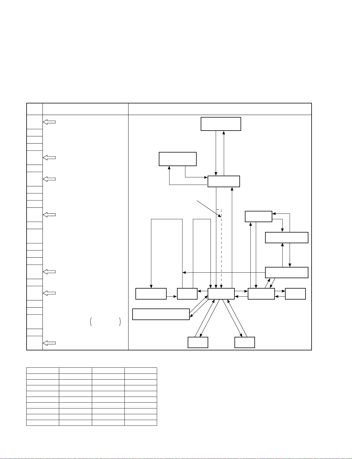
< MAINTENANCE TABLE 2 >
ERROR
DATE CODE POSITION
1 06 - 26 - 02 E01 08
2 - - - - - - - - - - - - - 3 - - - - - - - - - - - - - 4 - - - - - - - - - - - - - 5 - - - - - - - - - - - - - 6 - - - - - - - - - - - - - 7 - - - - - - - - - - - - - 8 - - - - - - - - - - - - - -
Service Overview
1-1. Maintenance Table on the Monitor Screen
To display the maintenance table, press “MENU” button with “REC/PLAY SPEED _(_)” button while
the fourth MENU <ALARM TIME> is displayed.
*
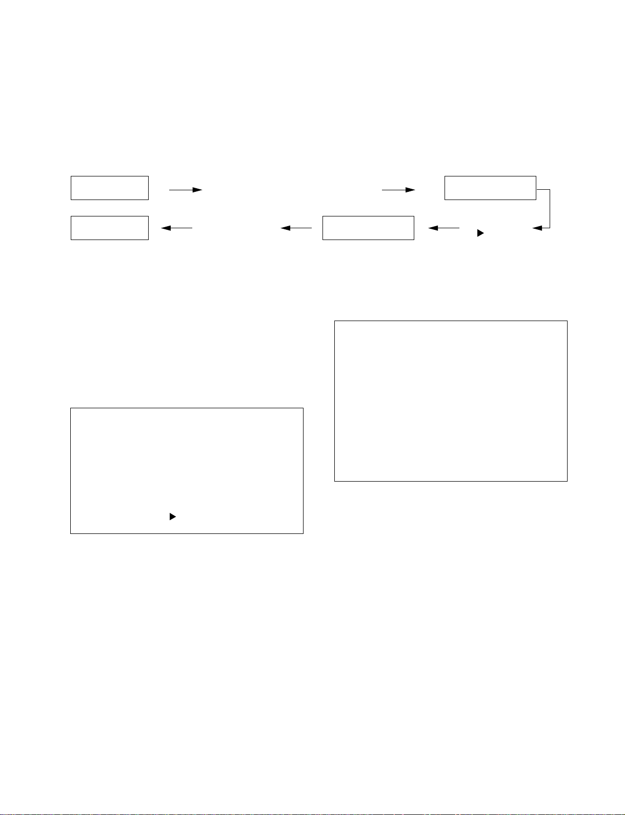
ALARM DATA Maintenance table 1
Maintenance table 1
The used time of each mode (part) is displayed, and can be
reset by items.
Access the maintenance-screen according to the above,
and then Fig. below is displayed and VIDEO HEAD will
blink.
Move the blinking to the item to be reset with “TRACKING – ( ▼ ) ” button and press the “MENU RESET”
button, and then the used time for the item will be reset.
Press “MENU” button with “REC/
PLAY SPEED –(_)” button
“MENU” buttonNormal screen
Maintenance table 2
Maintenance table 2
As shown in Fig. below Maintenance Table 2, <ERROR>
is displayed on the screen.
“TRACKING +
( )” button
< MAINTENANCE TABLE 1 >
USED TIME RESET
*
VIDEO HEAD
*
POWER ON
0 0 0 0 0 H
0 0 0 0 0 H
*
ALARM DATA
NEXT TABLE :
When the “MENU RESET” button is pressed during
display and resetting all data.
VIDEO HEAD: Used time of the video head (cylinder)
total hours.
n
Reset when the cylinder is replaced.
POWER ON: Hours of the power supply being.
ALARM DATA: Number of ALARM REC.
Total counts of ALARM.
n
The data for the maintenance tables are memoried in E
PROM, and the memory can be kept if the timer microcomputer is reset.
SVT-RA40/RA168
0 0 0 0 0 0
When the “MENU RESET” button is pressed during
display and resetting all data.
<ERROR> : Dates and error codes are displayed when
VCR happens to be in an abnormal condition
and the system is down.
The newest data is displayed in the first line,
and the old ones are moved down one by one.
Not-displayed old data is cleared automatically.
2
1-1

Error Codes (Self-Diagnosis Contents)
No. Problem Mechanism Operations and State After Occurrence
E01 The cylinder does not rotate.
The tape winds around the cylinder.
E02 The take-up reel does not rotate.
E03 The capstan motor does not rotate.
E04 The tape can not be loaded.
(But unloading can be performed.)
E05 The tape can be loaded with the cassette inserted.
But unloading can not be performed or the loading
and unloading cannot be performed with the
cassette inserted. (The tape guide is caught.)
E06 Front unloading cannot be performed when ejecting
the cassette. (Front loading can be performed.)
E07 Front loading and front unloading cannot be per-
formed when ejecting the cassette. (The cassette is
caught in the mechanism front.)
E09 The mechanism becomes 7 (INITIAL) while moving
from 1 (BRAKE), 2 (STOP), 3 (PLAY), 4 (STILL/
SLOW), and to 5 (REVERSE FRAME ADVANCE).
(The mechanism mode switch is faulty.)
E10 The capstan motor does not rotate, or the capstan
motor and the cylinder motor does not rotate with
the cassette inserted.
E11 The cylinder motor does not rotate with the cassette
inserted.
E12 The supply reel does the tape eject when tape
unloading.
E13 The tape cannot be loaded with the cassette
inserted.
E14 The tape cannot be loaded normally.
E15 The mechanism does not move to the correct
position after tape loading.
E16 Mechanism position “3” cannot be used during
intermittent recording.
Shift to the STOP mode.
Unload forcibly.
Shift to the STOP mode.
Shift to the STOP mode.
Unload, shift to the ST-BY mode, and the power goes off.
The power is forcibly turned off with the mechanism at its current
position.
Front loading, shift to the STOP mode or ST-BY mode.
The power is forcibly turned off with the mechanism at its current
position.
Carry out the tape take-up operations, and shift to STOP mode.
Shift to the EJECT mode.
Shift to the EJECT mode.
Shift to the EJECT mode.
Shift to the EJECT mode.
Shift to the EJECT mode.
The power is forcibly turned off with the mechanism at its current
position.
Shift to the STOP mode.
Mechanism Mode Display Contents
Mode. No. Mechanism mode Mode. No. Mechanism mode Mode. No. Mechanism mode
00 CASSETTE OUT 09 REC 32 INTERMITTENT REC
01 STAND-BY 12 CUE 33 REVERSE STILL
02 STOP 13 REVIEW
03 STILL 14 FAST FORWARD
04 REC-PAUSE 15 REWIND
06 FRAME ADVANCE 30 REVERSE PLAY
08 PLAY 31 REVERSE FRAME ADVANCE
1-2
SVT-RA40/RA168
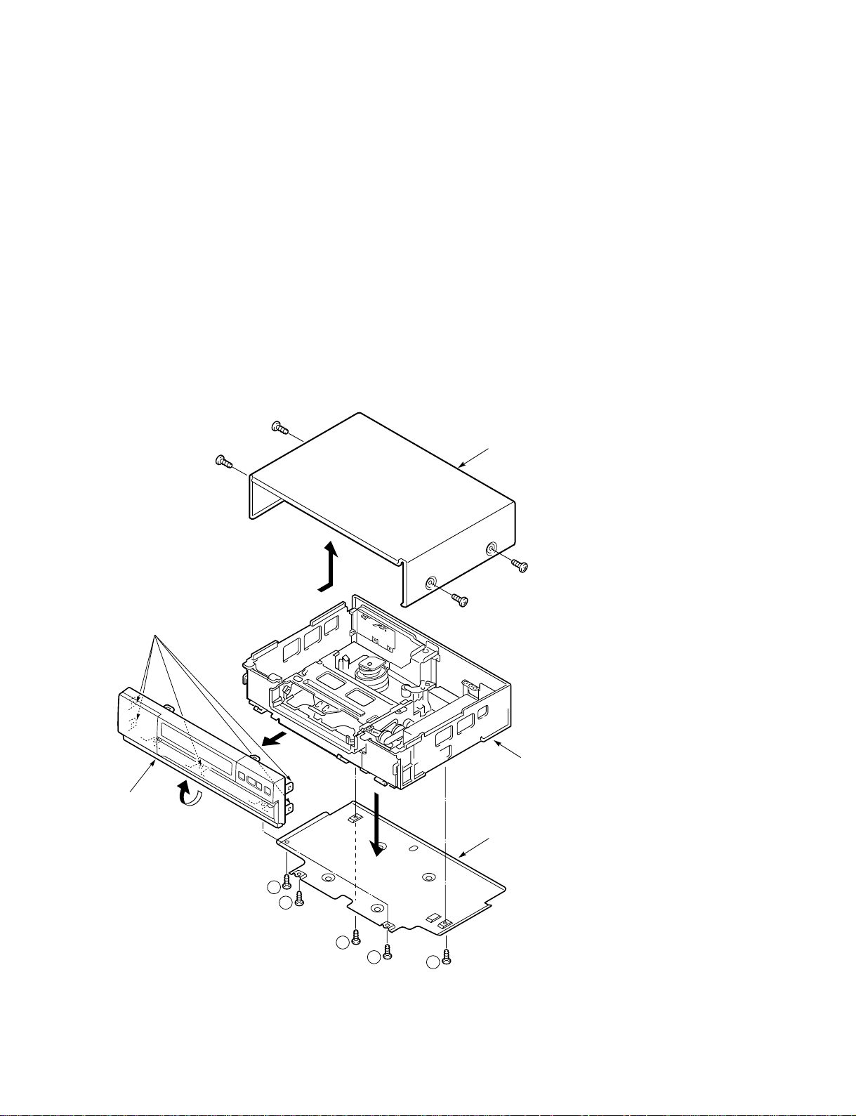
1-2. Removal of Cabinet, Mechanism Unit, and Main Board
1-2-1. Removing the Cabinet Parts
1. Remove the cabinet and bottom cover by removing the four screws (1) and five
screws (2).
2. Remove the front panel by removing the locks of the clamps (A) using a
screwdriver, etc. and slightly rotating the bottom part in the direction of the
arrow.
m
. Electrical adjustments for the this model can be performed with only the cabinet
removed.
. When replacing the bottom cover, do not tighten the screws (2) too much. Excess
tightness may damage the screws taps on the chassis.
1
Cabinet
1
Clamps (A)
Front Panel
1
1
Main Unit
Bottom Cover
2
2
2
2
2
SVT-RA40/RA168
Fig. 1-1-1
1-3
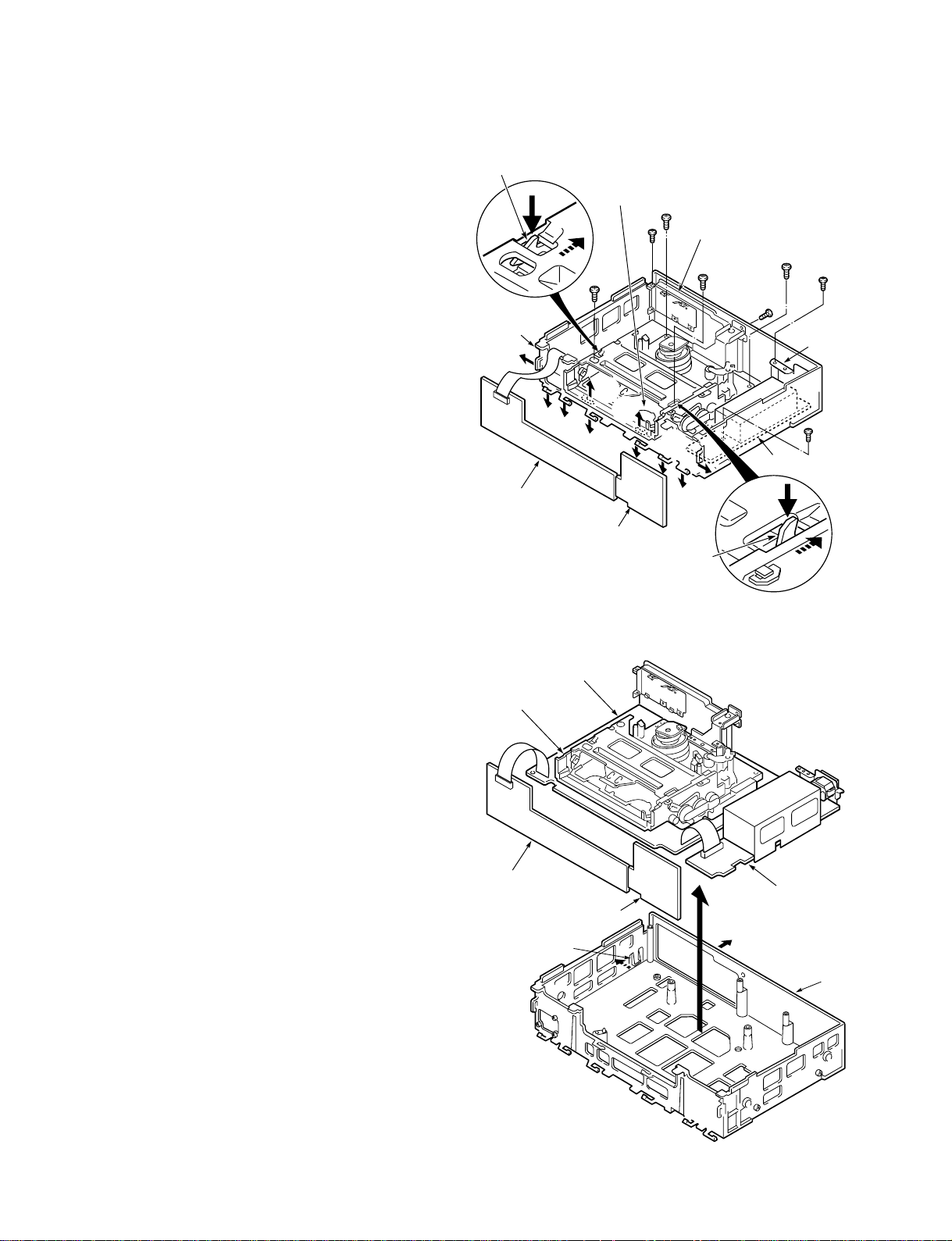
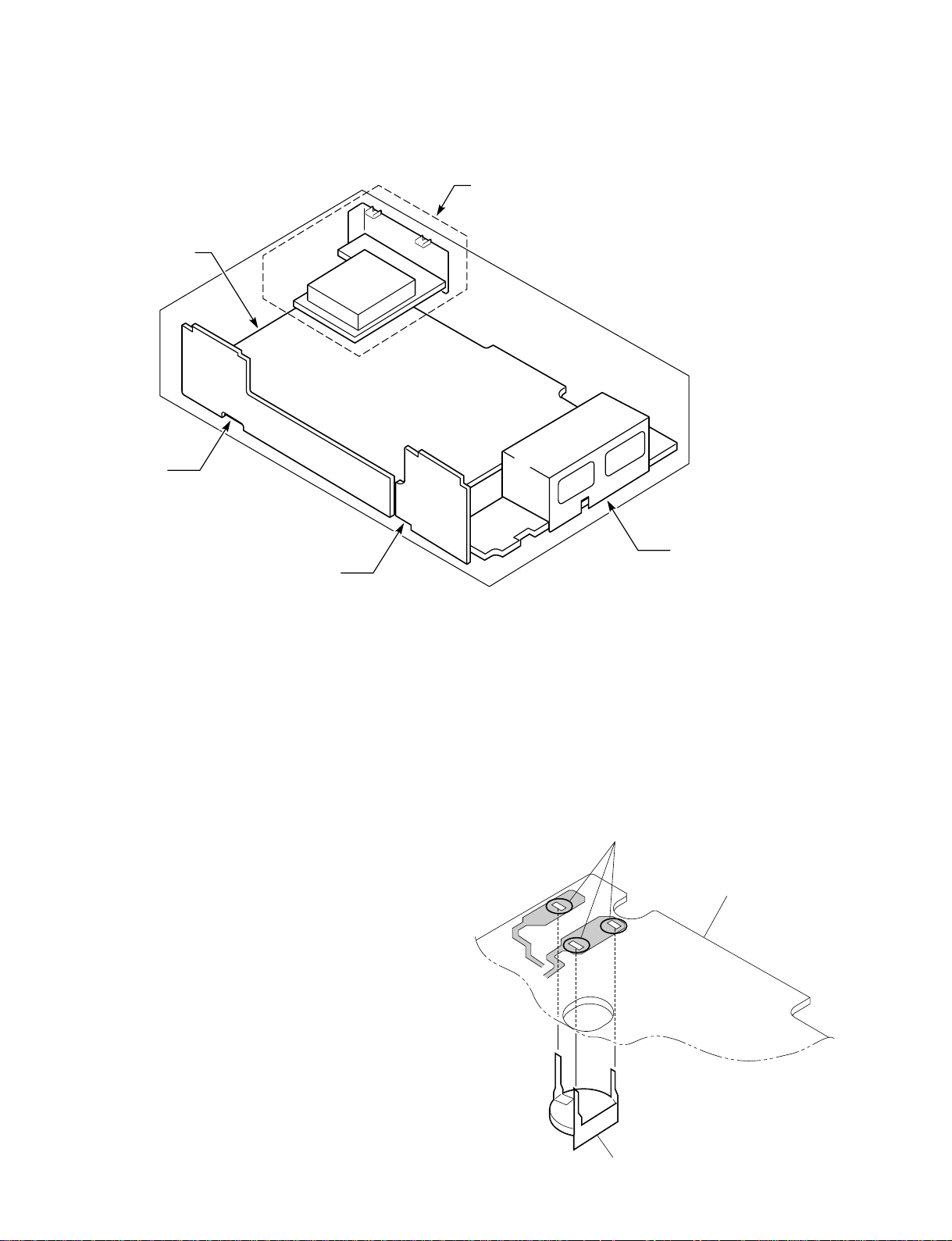
1-2-2. Removing the Mechanism Main Unit
and the CP-1 PWB Assembly
1. Spread out the lock clamps (B) and (C) in the arrow
direction slightly and remove the TM-1 PWB and TM2 PWB as shown in Fig. 1-1-2.
2. Remove the screws (3), (4) and (5) at the chassis.
3. Remove the screw (6) at the PW-1 PWB.
4. Remove the two screws (7) at the CP-1 board.
5. Remove the two screws (8) of the mechanism unit.
The two screws (8) of the cassette tray can be removed
easily by pushing the tray lock lever in the arrow
direction to remove the lock as shown in the enlarge
view A and by pushing the lid opener lever in the
arrow direction to remove the lock as shown in the
enlarge view B.
6. Lift up the whole mechanism unit and main board
(CP-1 PWB assembly), and as shown in Fig. 1-1-3,
push the two lock clamps (D) of the chassis in the
arrow direction so that they can be removed from the
chassis.
Tray Lock
Lever
Chassis
(B)
TM-1 PWB
A
(B)
(B)
(B)
Cassette Tray
8
(B)
(B)
(B)
TM-2 PWB
7
4
(C)
Lid Opener
Lever
Terminal Board
8
3
(C)
(C)
7
5
Holder
6
PW-1 PWB
CP-1 PWB Assembly
Mechanism Main Unit
TM-1 PWB
TM-2 PWB
Clamp (D)
B
Fig. 1-1-2
PW-1 PWB
Chassis
1-4
Fig. 1-1-3
SVT-RA40/RA168
1-3.
Temporarily Setting Up and Connecting CP-1 PWB Assembly
The following is an example of how to place and connect
the main board without a jig, when repairing the CP-1
PWB assembly.
1. Place the mechanism unit and main board up side
down as a whole on a flat surface with foil side of the
main board facing up.
2. Operete the unit using the buttons on TM-1 PWB and
TM-2 PWB.
CP-1 PWB Assembly (Foil side
PW-1 PWB
Screws
Mechanism
Main Unit
)
Terminal Board
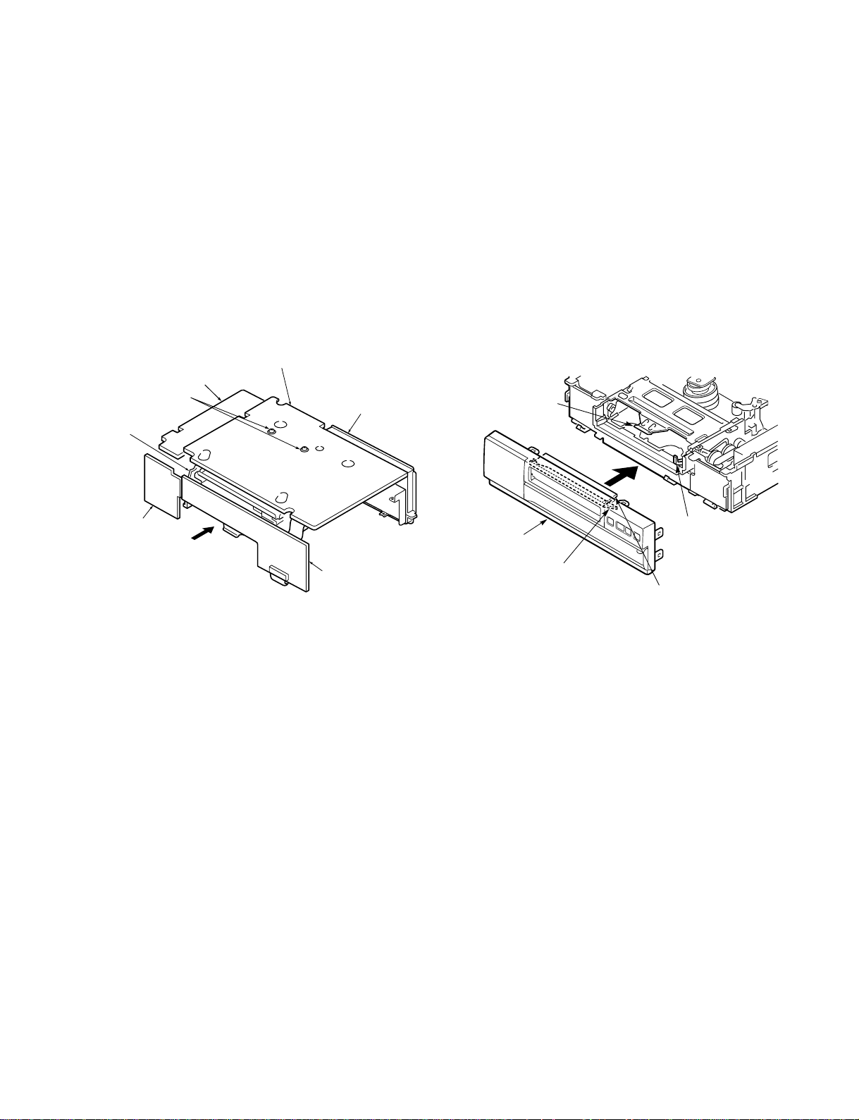
1-4. Installation of the Front Panel
When installing the front panel to the chassis after repaires
and adjustments.
1. Pressing down the door opener lever of the mechanism
main unit.
2. Set the cassette door to half-opened state as shown in
Fig. 1-1-5, and install the front panel to the chassis.
n
Opened cassette door position does not install the front
panel to the chassis.
Jutted part of
Cassette Holder
TM-2 PWB
Cassette Compartment
Fig. 1-1-4
TM-1 PWB
Front Panel
Cassette Door
(Position A)
Door Opener Lever
Cassette Door
(Position B)
Fig. 1-1-5
SVT-RA40/RA168
1-5
1-5. Circuit Board Locations
CP-1 PWB Assembly
TM-1 PWB
TM-2 PWB
CT-1 PWB
(Option for SVT-RS100)
PW-1 PWB
1-6. Lithium Battery for Backup
This unit is equipped with a backup battery(lithium
battery) to maintain the clock settings.
For replacement, be sure to use the specified part.
Replacement part: Z3901/CP-1 board
Part description: MnO2-Li (lithium battery)
Part No.: 1-756-091-11
Replacement
1. Remove the cabinet and bottom cover. (Refer to
Section 1-2-1.Removing the Cabinet Parts)
2. Place the mechanism unit and CP-1 board up side
down as a whole on a flat surface with foil side of the
CP-1 board facing up. (Refer to Section 1-3.Temporarily Setting Up and Connecting CP-1 PWB Assembly)
3. Unsolder the leads of the battery from the soldering
side of the CP-1 board and remove the battery.
Solder the backup battery in the reverse procedure of
removal.
Soldered
CP-1 PWB assembly
Battery
1-6
SVT-RA40/RA168

Section 2
Mechanical Adjustments
1. Maintaining and Checking the Mechanism
1-1. Regular Checks and Maintenance Items
To obtain full function and maximum performance from the set, and to stop it getting dirty or scratched,
we recommend that you carry out the following maintenance procedures and regular checks. The maintenance checks described in the following section should also be carried out without fail after carrying out
any repairs to the set.
Note: Oil and Grease
. Always use the specified brands of oil and grease. If you use a grease with the wrong viscosity, for
example, this can lead to all sorts of problems. Be careful to keep the oil and grease free of dust and
foreign bodies.
. A “drop” of oil is the amount of oil remaining on the tip of a rod with a diameter of 1. 5 mm after it is
dipped in oil to a depth of 1 cm and then taken out.
SVT-RA40/RA168
2-1
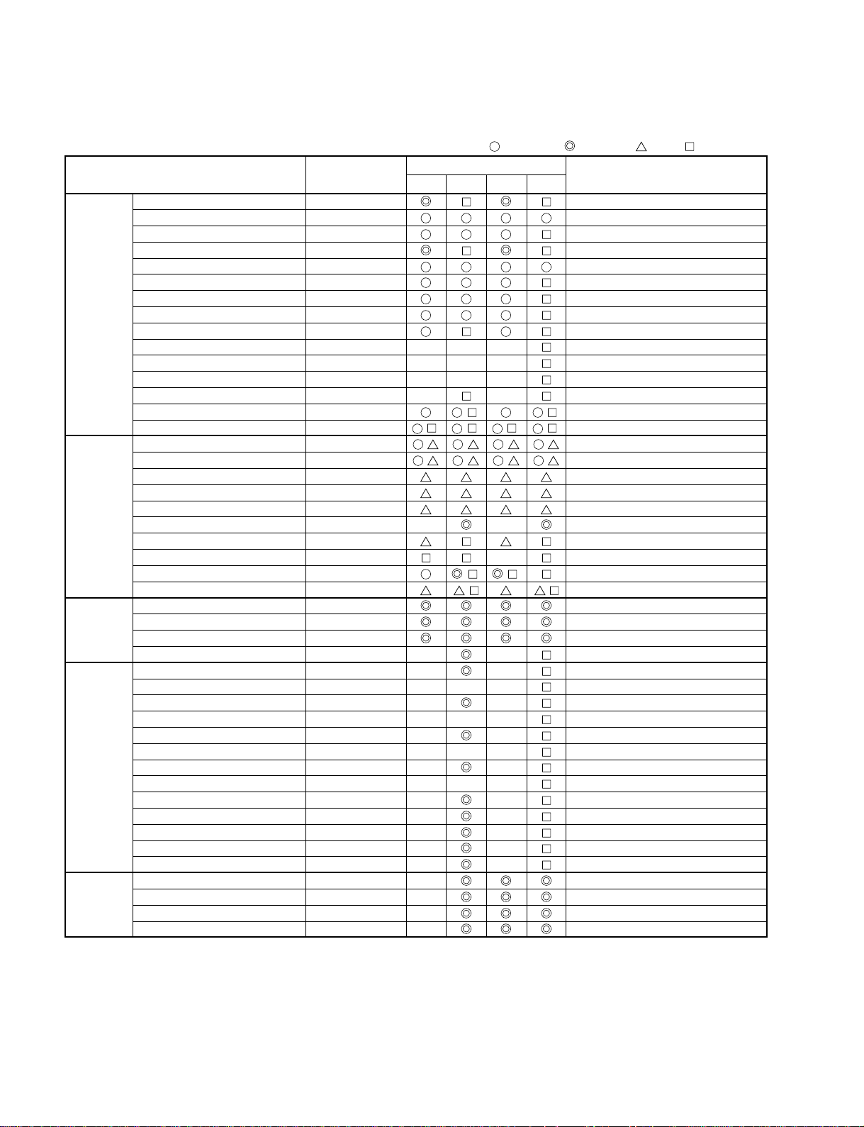
1-1-1. Regular Checks
Cleaning Check Oil Check, Replace
Part maintained Part Number
Band brake assembly 3-963-789-01
BT lever assembly 3-961-016-01
Full erase head 3-193-669-01
Cleaner roller assembly 3-977-067-01
Guide roller assembly 3-735-630-01
S incline mounting assembly 3-961-037-01
Tape path
system
T incline mounting assembly 3-961-039-01
ACE head A-8344-338-A
Pinch roller lever assembly 3-961-024-01
Pinch lift mounting 3-204-110-01
Pinch lift cam 3-961-027-01
Pinch cam gear 3-203-303-01
Cylinder chip earth 3-206-679-01
Cylinder complete A-8344-339-A ( ) ( )
Upper cylinder assembly 3-206-564-01 ( ) ( ) ( ) ( )
Supply reel assembly 3-977-065-01
Take up reel assembly 3-963-782-01
S reel gear 3-960-927-01
T reel gear 3-960-928-01
Reel drive Reel pulley 3-960-926-01
system Special washer 2.4 x 6 x 0.25 3-948-603-01
Clutch mounting complete A-8316-756-A
Reel belt 3-960-929-01
Capstan motor 3-203-331-01 ( ) ( )
Friction gear assembly 3-206-566-01
S brake assembly A-8325-366-A
Brake T brake assembly A-8325-367-A
system Capstan brake assembly A-8315-818-A
T soft brake assembly 3-963-784-01
Loading motor assembly 3-961-047-01
Damper 3-961-049-01
Worm gear complete 3-961-048-02
Main cam 3-206-567-01
Special washer 3.6 x 0.5 3-973-491-01
Loading Wheel gear 1 3-961-050-01
drive Wheel gear 2 3-963-793-01
system Opt pinch relay gear 3-206-568-01
Crescent slide 3-203-305-01
S load gear 3-960-995-01
Front rack gear 3-961-305-01
Start rack gear 3-961-306-01
Pinion gear 3-960-960-01
Perform-
ance
checks
This periodic maintenance check table changes considerably according to the using conditions and environment.
This is an annual periodic maintenance check table. Repeat this maintenance table every year.
As life may be shortened if foreign particles and dusts remain accumulated on the tape guides and rotating and contacting portions, clean if dirty.
Dusts and other foreign particles on the tape guides may also shorten the tape life and lower picture quality, therefore clean thoroughly.
Back tension torque PB back tension torque: 25~50 g.cm
FF, REW torque FF, REW: more than 600 g.cm
PLAY torque PLAY: 55~110 g.cm
REV torque REVIEW: 100~210 g.cm
Hours of use (H)
2000 4000 6000 8000
Remarks
2-2
SVT-RA40/RA168
1-2. Service Tools and Cleaning
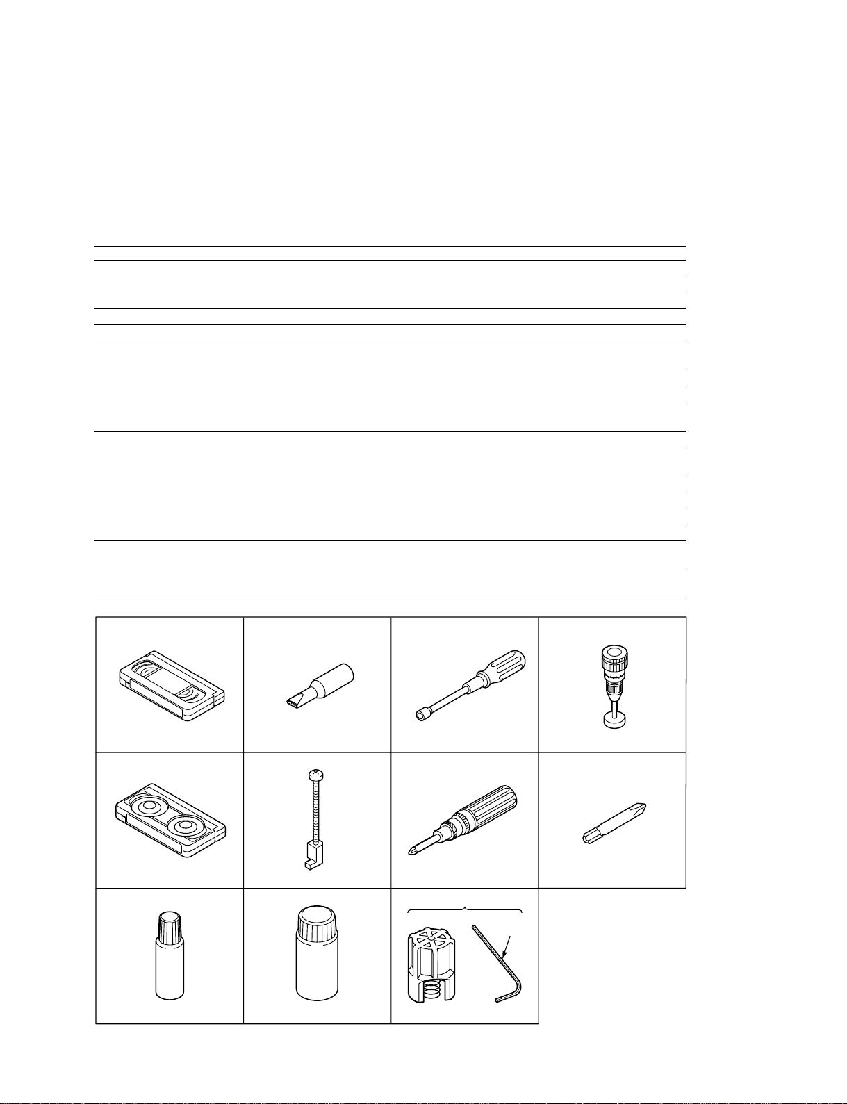
1-2-1. Service Tools
Notes on Alignment Tapes
Alignment tape from the list below, according to the transmission system of the VCR you are repairing.
Models with 525 scanning lines and a field frequency of 60Hz
No. Tool Tool No. Remarks
1 Alignment tape (VHJ-0005) —————— SP colour bar 1 kHz (normal)
2 Alignment tape (VHJ-0006) —————— SP monoscope 7 kHz or 6 kHz (normal)
3 Alignment tape (VHJ-0007) —————— EP monoscope No Audio signal
4 Alignment tape (VSJ-1001) —————— EP Sync signal 3 kHz (normal)
5 Eccentric screw driver (VHJ-0003) J-6082-044-A Used to adjust the tape path
6 Nut box (VHJ-0048) J-6082-045-A Used to adjust the height of the lever
load assembly
7 Torque dial gauge (VHJ-0004) —————— Used to measure reel winding torque
8 Cassette torque meter (VHJ-0016) —————— Used to measure back tension torque
9 Load lever assembly height J-6431-410-A Used to adjust the height of the load
adjustment tool (VHJ-0111) lever assembly
10 Torque gauge screwdriver (VHJ-0014) J-6082-047-A Used to adjust the tightening torque of screws
11 3 mm dia. bit for torque screwdriver J-6082-048-A Used to replace the bit of the torque gauge
(VHJ-0045) screwdriver
12 Oil (VHJ-0099) 7-661-018-18 ——————
13 Grease (VHJ-0100) 7-661-000-11 ——————
14 Grease (VHJ-0101) J-6090-014-A ——————
15 Grease (VHJ-0114) —————— ——————
16 Upper drum fitting tool kit (VHJ-0112) —————— Used to reassemble the upper cylinder
(includes VHJ-0113)
17 Hexagonal wrench (VHJ-0113 ) —————— Spare hexagonal wrench for upper drum
fitting tool kit
SVT-RA40/RA168
No.1, 2, 3, 4 No. 5 No. 6 No. 7
No. 8 No. 9 No. 10
No. 16
No. 17
No. 12 No. 13, 14, 15
No. 11
2-3
1-2-2. Cleaning
1. Cylinder (Drum)
Moisten a chamois with methyl alcohol and clean the video
head and the tape path surface of the cylinder. Be sure to
wipe horizontally in relation to the video head. If you wipe
vertically, or use excessive force, you can damage the
video head.
2. Tape Path System / Reel Drive System
Clean the pinch roller, the capstan shaft, the tape guides,
the FE head, the ACE head, the reel table, the pulley and
the reel belt with a soft cloth, or chamois, moistened with
methyl alcohol.
n
If the dirt on the tape guide cannot be cleaned off, replace
the tape guide.
Cylinder (Drum)
Tape path surface Video head
Fig. 1-2-2
2-4
SVT-RA40/RA168
2.
An Overview of the Mechanism
2-1. Names of the Main Parts
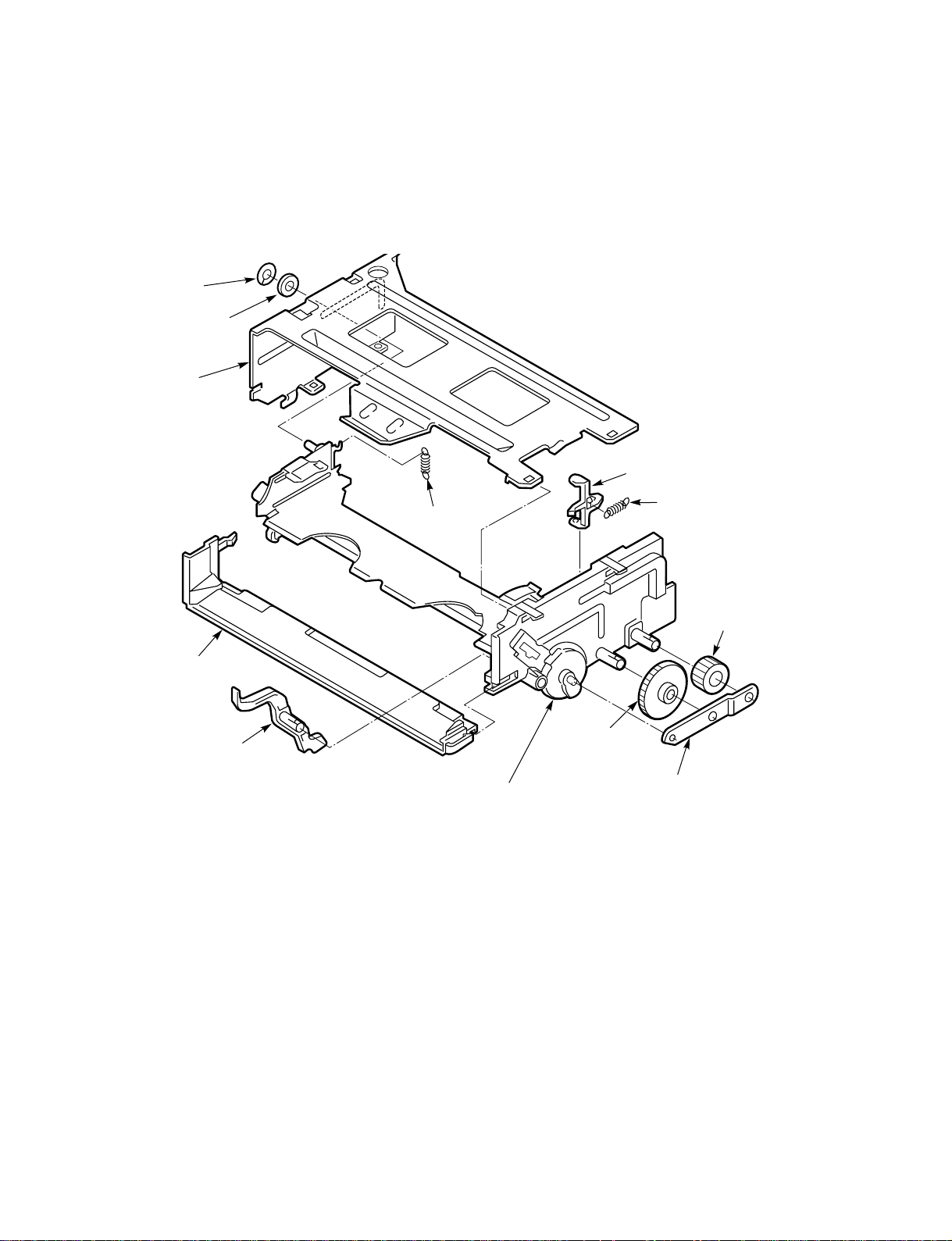
2-1-1. Cassette Mechanism Assembly
Special washer
Washer
Stand L
Tray lock spring
Release lever
Lid opener
spring
Under frame
Door opener lever
Fig. 2-1-1
Drive gear
Pinion gear
Lock gear
Gear holder
SVT-RA40/RA168
Fig. 2-1-1
2-5
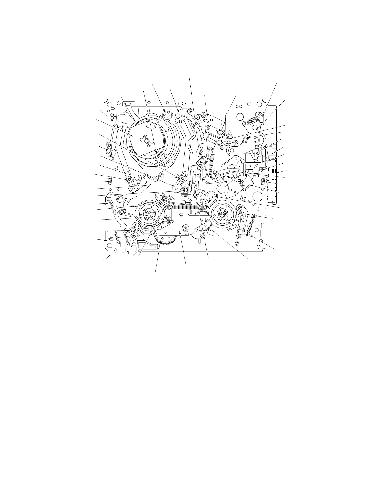
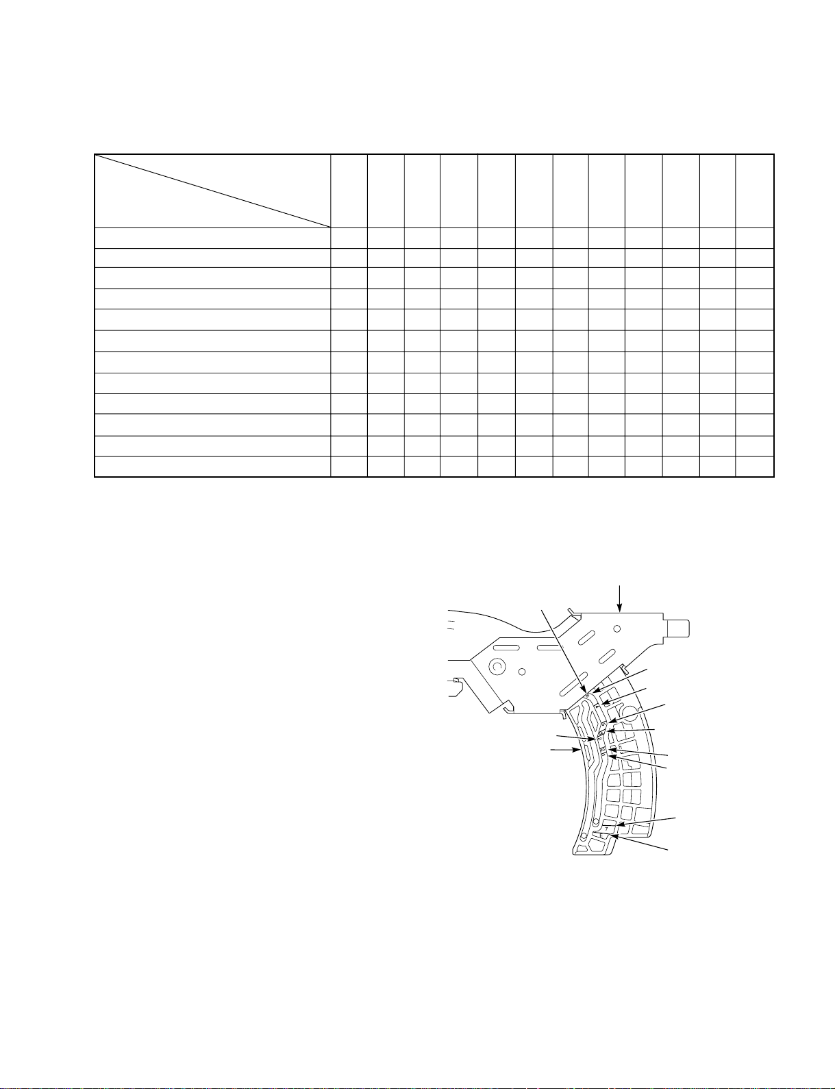
2-1-2. Topview
Cylinder mounting
Stator
Guide roller assembly
Full erase head
T incline mounting assembly
S incline mounting assembly
Guide roller assembly
Tape end sensor
BT lever assembly
Tape sensor LED
BT spring
Band brake assembly
Supply reel assembly
S soft lever
EP switch
EP sw lever
Cleaner roller assembly
Cylinder (Drum)
S brake
assembly
Rotor
S reel gear
Capstan brake assembly
Cleaner lever
Clutch mounting assembly
Audio R/P head
assembly
(ACE head)
T brake act slide T reel gear
Stopper lever
assembly
!
Dew sensor
!
Pinch roller lever
assembly
Capstan motor
Pinch lift cam
Pinch lift mounting
Front rack gear
Opener mounting
Pinch cam gear
Start rack gear
Load lever assembly
Tape top sensor
L guide act lever
assembly
T brake
assembly
T soft brake
assembly
Take up reel
asswembly
Fig. 2-1-2
2-6
SVT-RA40/RA168
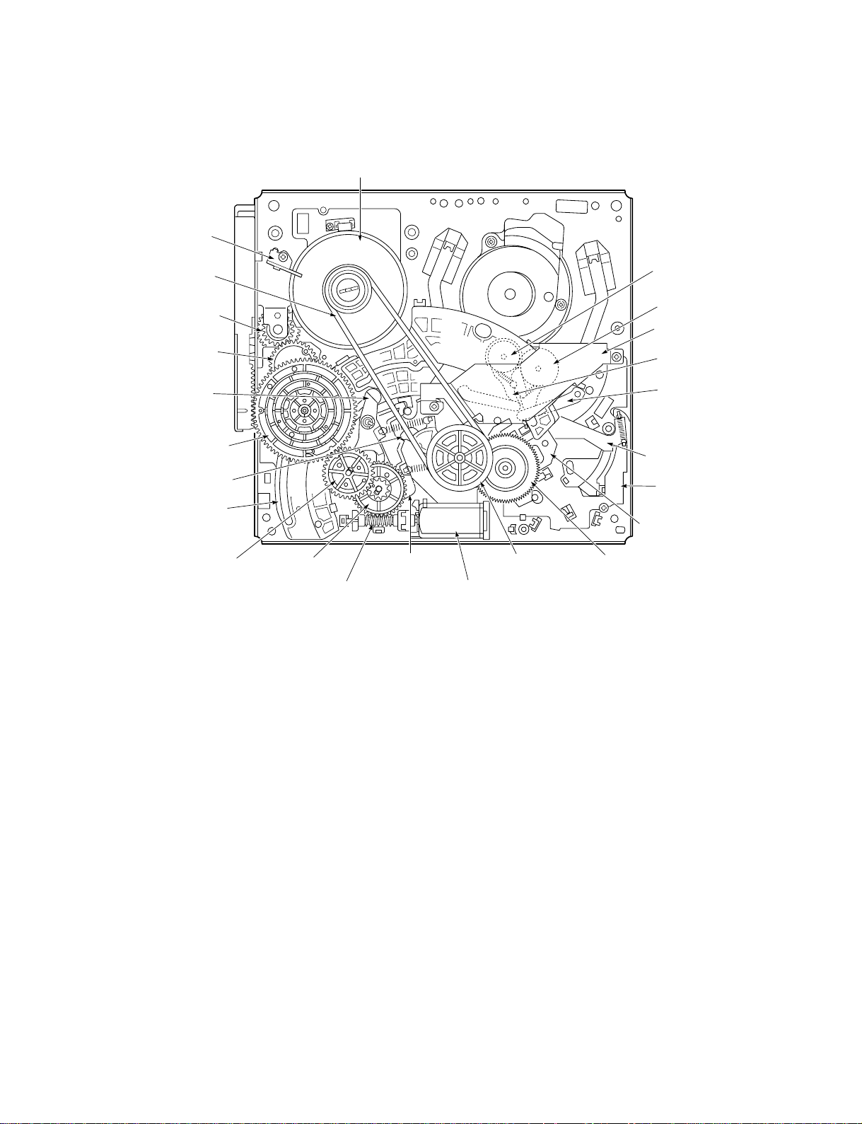
2-1-3. Underside
Capstan mounting
Capstan motor
Reel belt
Pinch cam gear
OPT pinch relay gear
Brake control lever
Main cam
Clutch change lever
Crescent slide
Wheel gear 2 Wheel gear 1
Brake act lever
assembly
Reel pulley
Friction gear assembly
S brake act slide
MC-1 PWB assembly
BT spring lever assembly
S load lever assembly
T load lever assembly
Crescent mounting
S load gear
T load gear
Loading motor assembly
Worm gear assembly
Fig. 2-1-3
SVT-RA40/RA168
2-7
2-2. An Overview of the Mechanism Modes
2-2-1. Mechanism Mode Switching Table
n
The letters and figures enclosed in circles in the mechanism mode column are the codes on the crescent
slide.
HEX
DATA
6
4
0
6
2
0
7
0
1
0
1
0
2
0
2
0
3
0
Mechanism mode The principal mode-switching states of the mechanism
EJECT E
Distinguished by whether the
EP switch is ON or OFF.
Horizontal shift section.
Vertical shift section.
IN REW R
INITIAL 7
Cleaner roller assembly:ON
S/T mounting incline assembly
pressure begins.
S/T mounting incline assembly
pressure ends.
REVIEW 1
R.STILL/R.SLOW 2
IDLER POS. 2
(Pinch roller OFF)
STILL/SLOW/REC (INTERVAL) 3
IN REW
(SHORT REW)
When loading is carried out starting
at the CASSETTE IN position
CASSETTE OUT
(EJECT)
INITIAL
REVIEW
R. STILL/R. SLOW
STILL/SLOW/REC
5
0
6
4
0
6
PLAY/STOP/REC 5
BRAKE pos. 4
FF/REW 6
POWER OFF
STAND BY
REC PAUSE
STAND BY/POWER OFF
Mode Switch Output Table
HEX DATA SW DATA 2 SW DATA 1 SW DATA 0
0HHH
1HHL
2HLH
2HLH
3HLL
4LHH
5LHL
6LLH
7LLL
2-8
CUEPLAYSTOPREC
REW FF
H: 5
L: 0
Low activ
SVT-RA40/RA168
2-2-2. Movement Check List for the Main Parts of the Mechanism
T brake assembly
S brake assembly
T soft brake assembly
S soft lever
BT lever assembly
BT spring
Pinch roller lever assembly
Clutch mounting assembly
Load lever assembly
Capstan brake assembly
S and T incline mounting assembly
Cleaner roller assembly
EJECT
IN REW
INITIAL
(UNLOADING)
(LOADING)
REV
IDLER
STILL/SLOW
PLAY/STOP
BRAKE
(POWER OFF)
FF/REW
OFF
OFF
OFF
ON
OFF
OFF
UP
PLAY
UNLO
OFF
OFF
OFF
OFF
OFF
ON
OFF
OFF
UP
PLAY
UNLO
OFF
OFF
ON
OFF
OFF
ON
OFF
OFF
UP
PLAY
UNLO
OFF
OFF
ON
OFF
ON
ON
OFF
OFF
ON
OFF
ON
ON
OFF
OFF
OFF
OFF
ON
OFF
ON
ON(W)
ON
PLAY
LO
OFF
OFF
OFF
OFF
ON
OFF
ON
ON(W)
OFF
PLAY
LO
OFF
OFF
OFF
OFF
OFF
OFF
ON
ON(S)
ON
PLAY
LO
ON
OFF
OFF
OFF
OFF
OFF
ON
ON(S)
ON
PLAY
LO
OFF
OFF
ON
ON
OFF
OFF
ON
ON(S)
OFF
PLAY
LO
OFF
OFF
ON/OFF
ON/OFF
OFF
OFF
ON
ON(W)
OFF
FF
LO
OFF
OFF
(S): Strength (W): Weakness
UP/
DOWN
DOWN/
UP
PLAY
LO
OFF
UNLO
(ON)
PLAY
LO
OFF
LO
(ON)
R.STILL/
R.SLOW
OFF
OFF
ON
OFF
ON
OFF
ON
PLAY
LO
ON
OFF
Principal parts
Mechanism mode
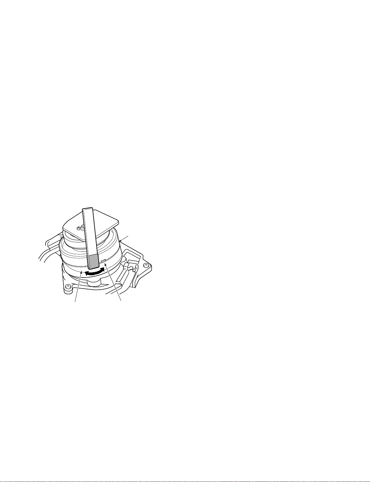
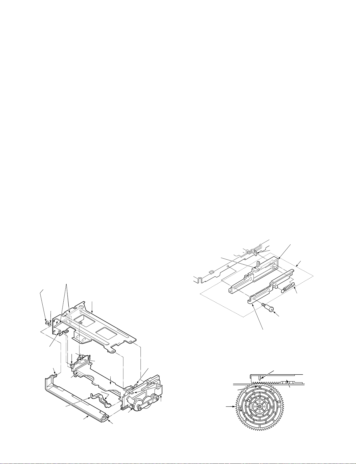
2-2-3. How To Check The Mechanism Mode
Position
You can tell which mode the mechanism is currently in by
looking at the codes and marking-lines on the crescent
slide on the underside of the mechanism chassis. The edge
of the crescent mounting is used as the reference line, as
shown in Fig. 2-2-2, and the marking-lines and symbols
indicating the mechanism modes are displayed on the
crescent slide, which slides against the edge of the crescent
mounting. The mechanism mode is read off from the
marking-line on the slide crescent which is aligned with
the reference-line on the crescent mounting.
Example: In Fig. 2-2-2, marking-line 6 is aligned with the
reference-line on the crescent mounting, so the mechanism is seen to be in FF/REW mode.
2-2-4. Self-diagnosis Display
Some models are equipped with the SELF-DIAGNOSIS
DISPLAYS function.
Use it as a means of finding out the symptoms and cause of
the error before performing repairs.
For details, refer to the separate service manual for the
respective models.
SVT-RA40/RA168
crescent mounting
is the reference-line.
2: R.STILL/R.SLOW
Crescent slide
Crescent mountingThe edge of the
6: FF/REW
4: BRAKE
(POWER OFF)
Fig. 2-2-2
5: PLAY/ STOP/
REC
3: STILL/SLOW/
REC (INTERVAL)
2: IDLER
1: REVIEW
7: INITIAL
E: EJECT
2-9
3. Disassembling the Main Parts of the Mechanism
3-1-1. Operating the Loading Motor by the
Manual Method
Points to Note
. When fitting the parts of the mechanism, refer to the
“Assembly Notes”, and proceed in the reverse of disassembly order.
. Dis-assembly and assembly should be carried out in
EJECT mode unless a movement mode is explicitly
specified. EJECT mode is the state in which the cas-sette
tape has been ejected.
. Clamps are used to prevent parts coming loose. When
removing a clamp, be careful not to force it, as this can
result in damage.
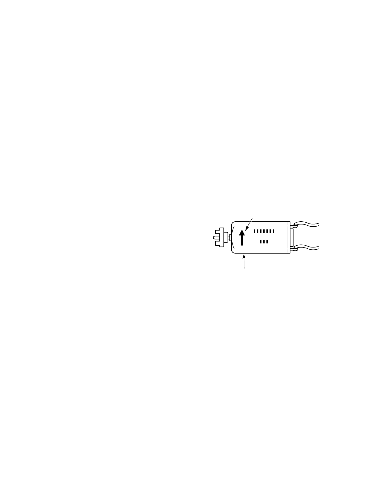
3-1. How to Make the Mechanism Move
In order to check a movement such as front loading, fron
unloading, tape loading, tape unloading, raising/lower-in
and pressing the pinch roller, you will need to operat
the loading motor. There are two methods of operatin
the loading motor, and these are explained in sections 3
1-1. The above movements can also be performed with-ou
operating the loading motor, by following the metho
explained in Section 3-1-2.
1. Refer to Section 3-2 and install the mechanism unit.
2. Using your finger, turn the loading motor located at
the rear of the mechanism unit. For EJECT, turn the
loading motor in the direction of the arrow on the
loading motor. For PLAY or FF/REW, turn it in the
opposite direction.
When rotating the loading motor in the EJECT direction with a tape slacken, stop the rotation of the
loading motor before beginning front unloading.
Rotate the capstan motor with your hand, wind the
slacked part of the tape, and rotate the loading motor
in the EJECT direction again.
When carrying out front loading, release the lock by
pressing down the tray lock lever 8 and the lid
opener lever 9 of the cassette mechanism assembly
(shown in Fig. 3-2-2).
The arrow which show the direction of EJECT
Loading motor
Fig. 3-1-1
2-10
SVT-RA40/RA168
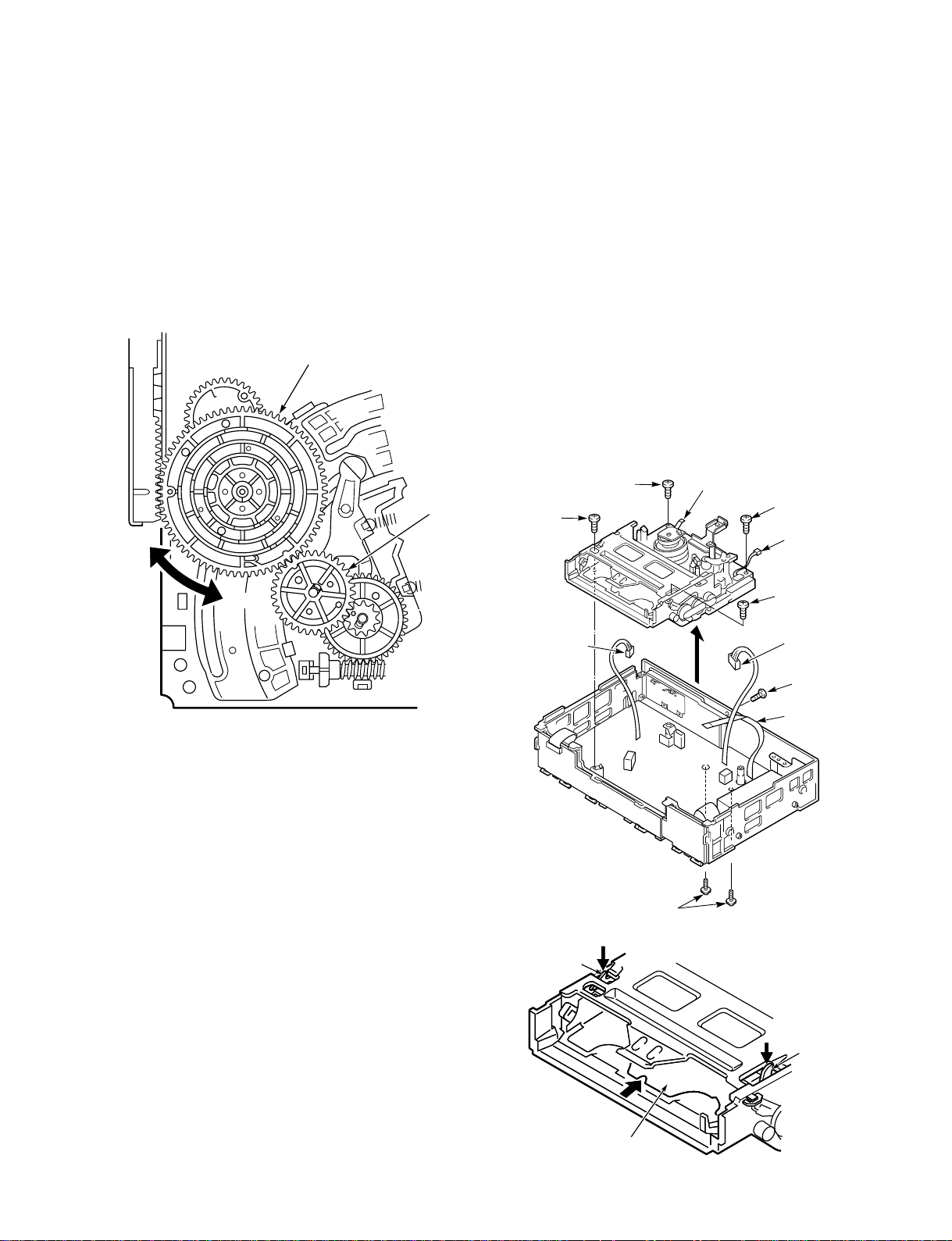
3-1-2. Making the Mechanism Move Using
7 Tray lock
lever
8 Lid opener
lever
6 Tray
the Manual Method
1. Refer to Section 3-2 and remove the mechanism unit.
2. Refer to Section 3-15 and remove the wheel gear 2.
3. If you turn the main cam counterclockwise, the mechanism will switch to a mode such as PLAY or FF/REW.
To switch from FF/REW mode to EJECT mode, turn
the main cam clockwise.
Main cam
3-2. Mechanism Unit
1. Remove the top cover, bottom cover and front cabinet
assembly.
2. Unplug the flat cable 1 from the CP-1 PWB assembly on the cylinder (drum), and unplug the ACE/FE
head connectors 2.
3. Unplug the flat cable from the stator.
4. Unplug the dew sensor connector 4.
5. Remove the four screws 5, then lift up the mechanism unit. The tray 6 will stop you removing the two
screws 5 on the front, so release the lock by pressing
down the tray lock lever 7 and the lid opener lever
8 shown in Fig. 3-2-2, then slide off the tray 6.
Move the tray by referring to Section 3-1 and turn the
loading motor in the PLAY direction.
CW
CCW
Fig. 3-1-2
Wheel gear 2
5
Screw
2
FE head
connector
5 Screw
1 Flat cable
5 Screw
4
Dew sensor
connector
5 Screw
2
ACE head
connector
3 Flat cable
Fig. 3-2-1
SVT-RA40/RA168
Fig. 3-2-2
2-11
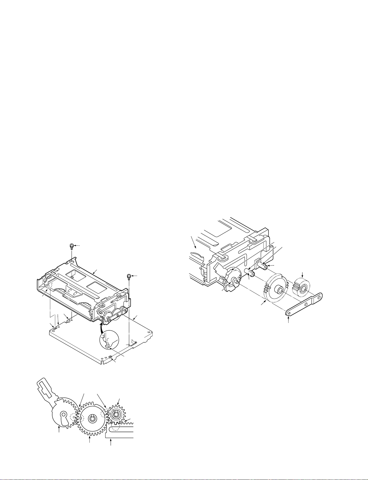
3-3. Cassette Drive Mechanism
3-3-2. Cassette Drive Gear
3-3-1. Cassette Mechanism Assembly
1. Put the VCR into EJECT mode.
2. Remove the two screws 1.
3. Lift up the back of the cassette mechanism assembly
2 slightly, and remove the two hooks 3 on the front.
Assembly Notes:
1. The cassette mechanism assembly and the mecha-nism
chassis should both be fitted in EJECT mode.
2. Check that the two hooks 3 have snapped into the
mechanism chassis, and make sure that the two holes
4 in the cassette mechanism assembly are aligned
with the two dowels 5 on the mechanism chassis.
3. Make sure that the big tooth on the pinion gear of the
cassette mechanism assembly slots properly into the
deepest gap in the start rack gear, as shown in Fig. 3-3-
2.
4. When fitting the two screws 1, use the torque gauge
screwdriver (VHJ-0014). Give the screws a tightening
torque of 5 kg.cm.
1 Screw
2 Cassette mechanism
assembly
1 Screw
3
Hook
5
Dowel
4 Hole
Mechanism
chassis
1. Refer to Section 3-3-1 and remove the cassette mechanism assembly.
2. Remove clamps 1 and 2, then remove the gear
holder 3.
3. Remove the clamp 1, then remove the pinion gear
4.
4. Remove the clamp 2, then remove the lock gear 5.
Assembly Notes:
1. Put the tray in the EJECT mode position before fitting
any parts.
2. Apply grease (VHJ-0100) to the gear mounting shafts,
all the gear teeth, and the cam part of the drive gear
6.
3. Ensure that the drive gear, the lock gear and the pinion
gear interlock correctly, as shown in Fig. 3-3-2.
4. Make sure the clamps 1 and 2 snap in to the gear
holder 3.
Tray
6 Drive gear
2 Clamp
5 Lock gear
(grease the outer rim
of the teeth)
Fig. 3-3-3
Apply
grease
4 Pinion gear
(grease the
1
outer rim of
Clamp
the teeth)
3 Gear holder
2-12
Drive gear
Fig. 3-3-1
Ensure correct
interlocking
Lock gear
Start rack gear
Fig. 3-3-2
3 Hook
4 Hole
Pinion gear
Ensure correct
interlocking
SVT-RA40/RA168
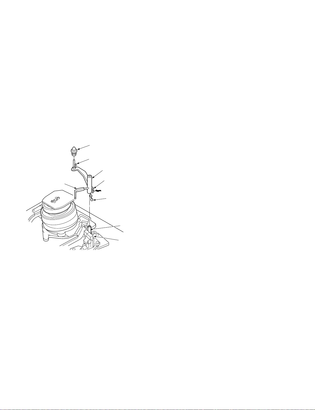
3-3-3.
1 Special screw
4 Spring
3
Shaft
7 Start rack gear
(apply grease to
inside of groove)
2 Front rack
gear assembly
5 Front rack gear
(apply grease to
inside of groove)
6 Clamp
Door Opener, Under Frame and Stand L
3-3-4. Start Rack Gear and Front Rack Gear
1. Remove the cassette mechanism assembly, referring to
Section 3-1.
2. Remove the two clamps 1 and take out the under
frame 2, pulling it towards you.
3. Press down the tray lock lever 3 and the lid opener
lever 4, and loosen the tray 5, lifting it away from
you. In this state, press the clamp 6 and remove the
door opener lever 7.
4. Remove the special washer !], then remove the
washer !\.
5. Remove the two clamps 8 and take out the stand L
9.
Be careful not to exert too much force on the clamps
8, as this could cause damage.
Assembly Notes:
1. Apply grease (VHJ-0100) to the grooves !- on the
stand L, the inside of the hole ![ in the drive shaft !=,
and the mounting hole !; in the door opener lever of
the stand R.
2. Before fitting the stand L 9, be sure to move the tray
5 back as far as the EJECT mode position. Put the
two pins 0 on the tray 5 into the grooves !- on the
stand L. Put the drive shaft != into the hole ![.
3. Be sure to fasten the two clamps 1 and the clamp 6
on the stand R, and to fasten the two clamps 8 on the
stand L.
1. Remove the mechanism unit, referring to Section 3-2.
2. Remove the cassette mechanism assembly, referring to
Section 3-3-1.
3. Remove the special screw 1. When you do this, slide
the front rack gear assembly 2 towards the front until
it stops, then take it off the shaft 3. Take care not to
damage the shaft 3.
4. Remove the spring 4.
5. Remove the clamp 6 on the front rack gear 5, then
remove the start rack gear 7.
Assembly Notes:
1. Apply grease (VHJ-0100) to the front rack gear 5
and all over the inside of the groove on the start rack
gear 7.
2. Align the positioning mark 8 on the front rack gear
5 with the mark 0 on the main cam 9.
3. When installing the cassette mechanism assembly,
refer to Section 3-3-1 and align the start rack gear with
the pinion gear.
!]
Special
washer
!\
Washer
3-4. Cleaner Roller Assembly
1. Remove the clamp 1 and take out the cleaner lever
2. When you do this, be careful not to bend the
plastic springs A and B on the cleaner lever 2.
2. Remove the clamp 3, and take out the cleaner roller
assembly 4. Be careful not to touch the sponge on the
cleaner roller assembly 4.
Assembly Notes:
1. When mounting the cleaner lever 2 on the shaft 5,
press the clamp 1 in the direction shown by the
arrow, and snap it into the mounting 6 on the audio
R/P head assembly.
4 Cleaner roller assembly
3 Clamp
2 Cleaner lever
B Plastic spring
1 Clamp
A Plastic spring
5 Shaft
6 Mounting
Fig. 3-4-1
2-14
SVT-RA40/RA168
 Loading...