

Page 1
Wall-Mount
Bracket
Operating Instructions
Manuel d’instructions
Manual de instrucciones
US
FR
ES
SU-WL810
4-588-644-13(1)
Page 2
On Safety
Thank you for purchasing this product.
To Customers
Sufficient expertise is required for
installing this product. Be sure to
subcontract the installation to Sony
dealers or licensed contractors and pay
special attention to safety during the
installation. Sony is not liable for any
damages or injury caused by
mishandling or improper installation, or
installing any other than the specified
product. Your Statutory Rights (if any) are
not affected.
To Sony dealers
Sufficient expertise is required for
installing this product. Be sure to read
this instruction manual thoroughly to do
the installation work safely. Sony is not
liable for any damages or injury caused
by mishandling or improper installation.
Please give this manual to the customer
after installation.
This instruction manual shows the correct
handling of the product and important
precautions necessary to prevent accidents.
It is your responsibility to read, thoroughly
understand, and follow all instructions in this
instruction manual. Failure to do so may
result in serious personal injury or property
damage, and may void the warranty. Keep
this manual available for future reference.
Products by Sony are designed with safety in
mind. If the products are used incorrectly,
however, it may result in a serious injury
through fire, electric shock, the product
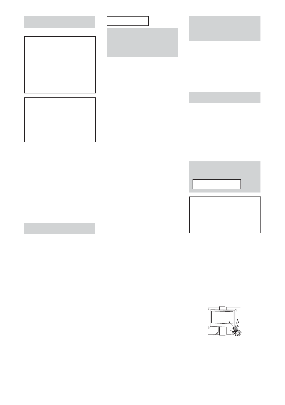
toppling over, or the product dropping. Be
sure to observe the precautions for safety to
prevent such accidents.
CAUTION
Specified products
This Wall-Mount Bracket is designed for use
with the products specified TVs. For TVs,
refer to their “Reference Guide” to verify that
the Wall-Mount Bracket can be used.
US
2
To Customers
WARNING
If the following precautions are not
observed, serious injury or death
through fire, electric shock, or the
product dropping can result.
Be sure to subcontract
the installation to
licensed contractors and
keep small children away
during the installation.
If the Wall-Mount Bracket or the TV is not
installed correctly, the following accidents
may occur. Be sure licensed contractors carry
out installation.
The TV may fall and cause a serious injury
such as a bruise or a fracture.
If the wall on which the Wall-Mount
Bracket is installed is unstable, uneven, or
not perpendicular to the floor, the unit
may fall and cause injury or property
damage. The wall should be capable of
supporting a weight of at least four times
the TV weight.
(Refer to your TV’s “Reference Guide” for
its weight.)
If the installation of the Wall-Mount
Bracket on the wall is not sufficiently
sturdy, the unit may fall and cause injury or
property damage.
Be sure to subcontract
moving or dismounting
of the TV to licensed
contractors.
If persons other than licensed contractors
transport or dismount the TV, it may fall and
cause injury or property damage. Be sure
that two or more persons carry or dismount
the TV.
Do not remove screws,
etc., after mounting the
TV.
If you do so, the TV may fall and cause injury
or property damage.
Do not make alterations
to the parts of the WallMount Bracket.
If you do so, the Wall-Mount Bracket may fall
and cause injury or property damage.
Do not mount any
equipment other than
the specified product.
This Wall-Mount Bracket is designed for use
with the specified product only. If you mount
equipment other than specified, it may fall or
break, and cause injury or property damage.
Do not apply any load
other than the TV on the
Wall-Mount Bracket.
Do not shake the TV left/
right, up/down.
If you do so, the TV may fall and cause injury
or property damage.
Do not lean on or hang
from the TV.
Do not lean on or hang from the TV as it may
fall on you and cause serious injury.
CAUTION
If the following precautions are not
observed, injury or property damage
may occur.
Do not handle the
product with excessive
force during cleaning or
maintenance.
Do not apply excessive force on the topside
of the TV. If you do so, the TV may fall and
cause injury or property damage.
Precautions
If you use the TV installed on the
Wall-Mount Bracket for a long time, the
wall behind or above the TV may become
discolored or the wallpaper may come
unstuck, depending on the material of the
wall.
If the Wall-Mount Bracket is removed after
installing it on the wall, the screw holes are
left.
Do not use the Wall-Mount Bracket in a
place where it is subjected to mechanical
vibrations.
Installing the WallMount Bracket
To Sony Dealers
WARNING
The following instructions are for Sony
dealers only. Be sure to read safety
precautions described above and pay
special attention to safety during the
installation, maintenance and checking
of this product.
Do not install the WallMount Bracket on wall
surfaces where the
corners or the sides of
the TV protrude away
from the wall surface.
Do not install the Wall-Mount Bracket on wall
surfaces such as a pillar, where the corners
or the sides of the TV protrude away from
the wall surface. If a person or object
happens to hit the protruded corner or side
of the TV, it may cause injury or property
damage.
Do not install the TV over
or under an airconditioner.
If the TV is exposed to water leaks or air
current from an air conditioner for a long
time, it may cause a fire, an electric shock or
a malfunction of the TV.
Page 3

Be sure to install the
W
all-Mount Bracket
securely to the wall
following the instructions
in this instruction
manual.
If any of the screws are loose or fall out, the
Wall-Mount Bracket may fall and cause injury
or property damage. Be sure to use the
appropriate screws for the material of the
wall and install the unit securely, using
supplied screw and anchors.
Be careful not to subject
the TV to shock during
installation.
If the TV is exposed to shock, it may fall or
break apart. This may cause injury.
Be sure to install the TV
on a wall that is both
perpendicular and flat.
If you fail to do so, the TV may fall and cause
injury.
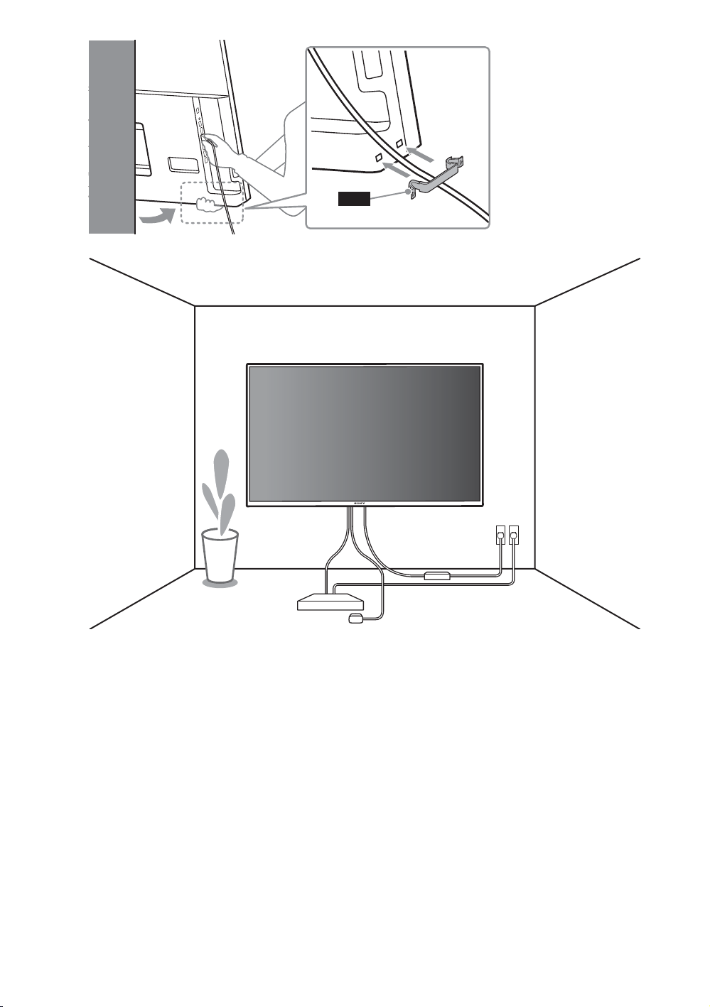
After proper installation
of the TV, secure the
cables properly.
If people or objects get tangled with cables,
this may result in injury or damage to the TV.
Do not allow the AC
power cord or the
connecting cable to be
pinched.
If the AC power cord or the connecting cable
is pinched between the unit and the wall or
is bent or twisted by force, the internal
conductors may become exposed and cause
a short circuit or an electrical break. This may
cause a fire or an electric shock.
US
Be sure to use the
supplied screws and
attachment parts
properly following the
instructions given in
this instruction
manual. If you use
substitute items, the
TV may fall and cause
bodily injury to
someone or damage to
the TV.
Be sure to assemble the
bracket properly
following the instructed
procedure explained in
this instruction manual.
If any of the screws are loose or fall out, the
TV may fall and cause bodily injury to
someone or damage to the TV.
Be sure to tighten the
screws securely in the
designated position.
If you fail to do so, the TV may fall and cause
bodily injury to someone or damage to the
TV.
US
3
Page 4
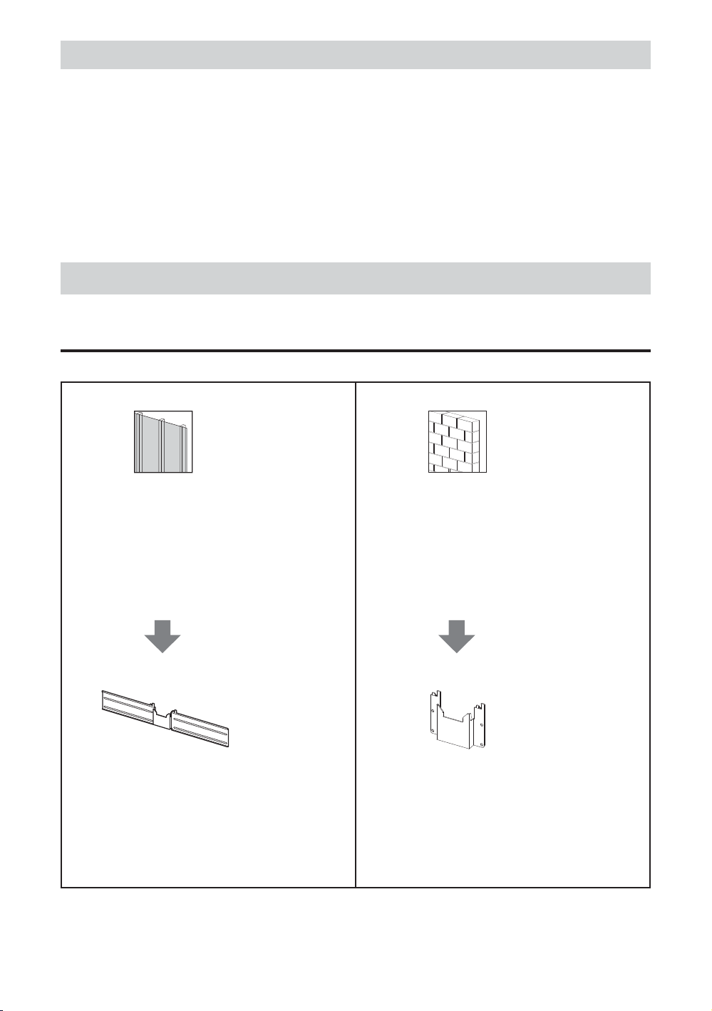
Table of Contents
Before getting started ............................................................................................................................. 4
What is your wall made of? ..........................................................................................................................................4
Supplied items ......................................................................................................................................... 5
Tools needed ........................................................................................................................................... 5
Preparing for the installation of the TV ................................................................................................... 6
Attaching the Lateral Shift Bracket to the Dry Wall with Studs ........................................................10
Attaching the Wall-Mount Bracket to the Solid Concrete or Concrete Block................................... 15
Specifications ..........................................................................................................................................19
Before getting started
Firstly, check the type of the wall to install the TV.
The Wall-Mount Bracket differs depending on the type of the wall.
What is your wall made of?
Dry wall with studs
Precautions
Maximum dry wall thickness:
16 mm (5/8 inch).
Ensure that the inner wood stud size is at
least 51 x 102 mm (2 x 4 inch) for common
or 38 x 89 mm (1 1/2 x 3 1/2 inch) for
nominal.
Keep minimum 406 mm (16 inch) horizontal
space between fasteners.
Use the Lateral Shift Bracket.
Steps
Attach the Table-Top Stand to the TV.
Attach the U-shaped Bar and cables to the
TV.
Install the Lateral Shift Bracket to the wall.
Detach the Table-Top Stand from the TV.
Hang the TV to the wall.
Solid Concrete or Concrete Block
Precautions
Mount the Wall-Mount Bracket directly
onto the solid concrete wall.
Ensure that the thickness of solid concrete
wall is at least 203 mm (8 inch).
Ensure that the size of each concrete block
is at least 203 x 203 x 406 mm
(8 x 8 x 16 inch).
Use the Wall-Mount Bracket.
Steps
Attach the Table-Top Stand to the TV.
Attach the U-shaped Bar and cables to the
TV.
Install the Wall-Mount Bracket to the wall.
Detach the Table-Top Stand from the TV.
Hang the TV to the wall.
US
4
Page 5

Supplied items
WM1 WM2 WM3 WM4 WM5
UB 75 UB 65 UB 55 TM
UB 75
UB 65
UB 55
M6L20
LIMITED WARRANTY
WS1
WS2
WW1
8 mm x 60 mm
(11/32 inch x 2 3/8 inch)
(4)
WA1
(4)
WW2
US
(2)
WA2
4.8 mm x 32 mm
(7/32 inch x 1 5/16 inch)
(2)
(4)
(2)
Tools needed
*1
5.5 mm (7/32 inch) 10 mm (3/8 inch)
*2
*1 Only for dry wall with studs *2 Only for solid concrete or concrete block
US
5
Page 6
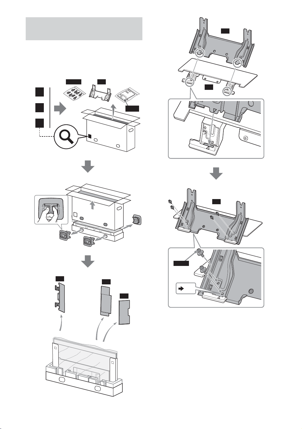
Preparing for the
installation of the TV
1 Put the TV on the Table-Top
Stand to prepare the installation
of the Wall-Mount Bracket.
2
SN
75
65
55
M5L12
1
SN
SB
CL(S)
SN
2
US
6
SB
M5L12
CC
x 4
SC
Page 7
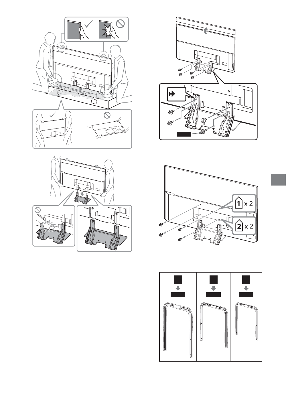
3
4
5
x 4
M5L12
Remove the screws from the
6
rear of the TV.
US
7 Choose the U-shaped Bar
according to your TV inch size.
75
UB 75
UB 75
65
UB 65
UB 65
55
UB 55
UB 55
US
7
Page 8
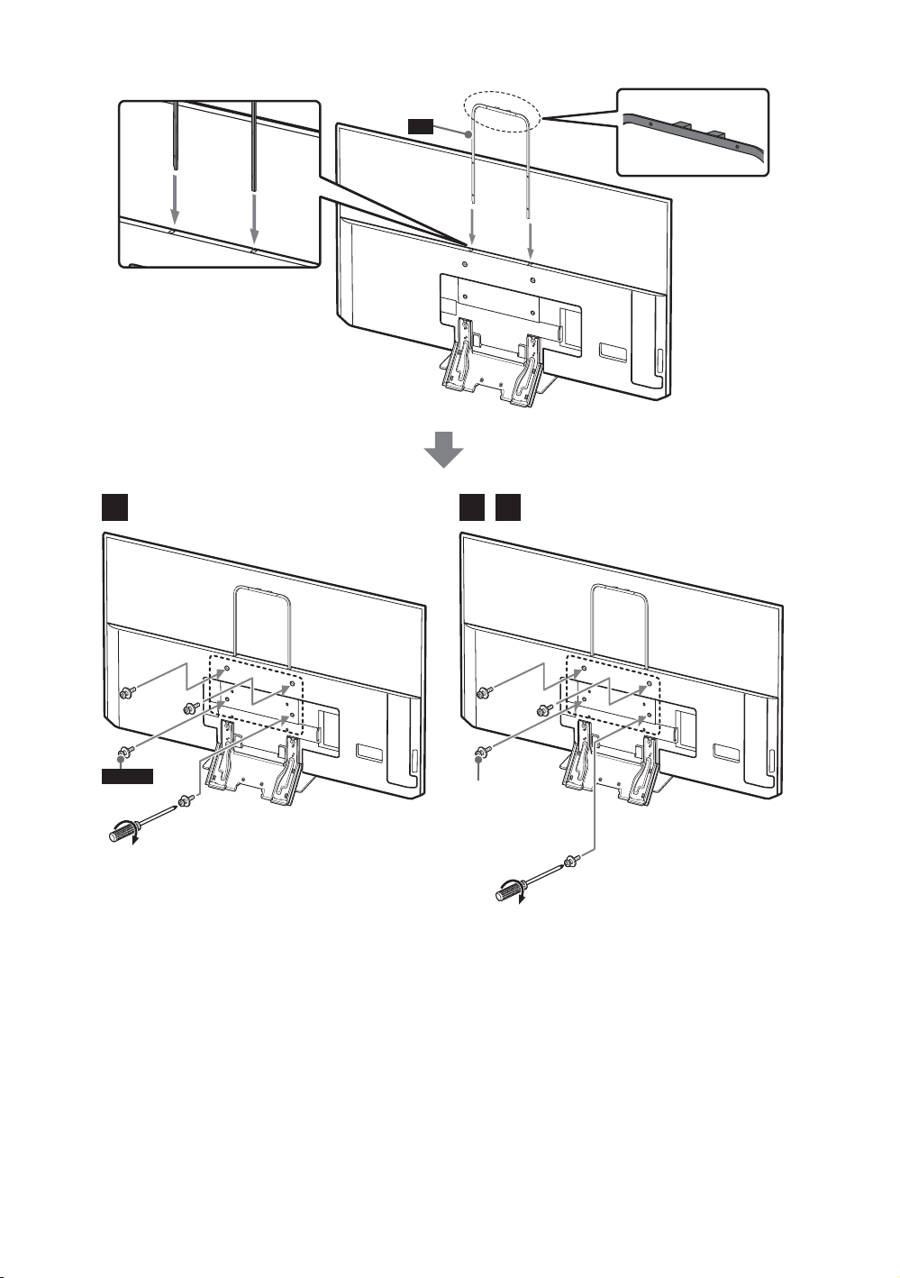
8 Attach U-shaped Bar to the rear of the TV.
UB
75
M6L20
1.5 N∙m/1,5 N∙m
{15 kgf∙cm}
65 55
previously
removed
1.5 N∙m/1,5 N∙m
{15 kgf∙cm}
US
8
Page 9
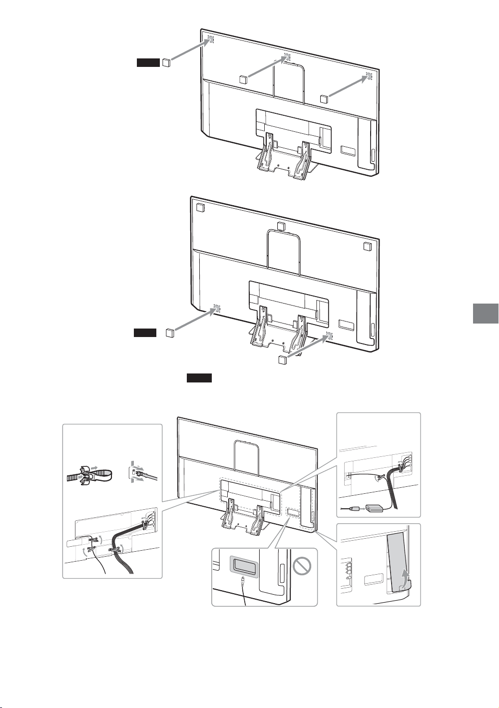
9
WM3
US
*
WM5
* Only for lateral shift bracket
WM4
10 Connect and bundle the cables.
12
3
9
US
Page 10
Attaching the Lateral Shift Bracket to the Dry Wall with
Studs
Dry wall with studs
WM4
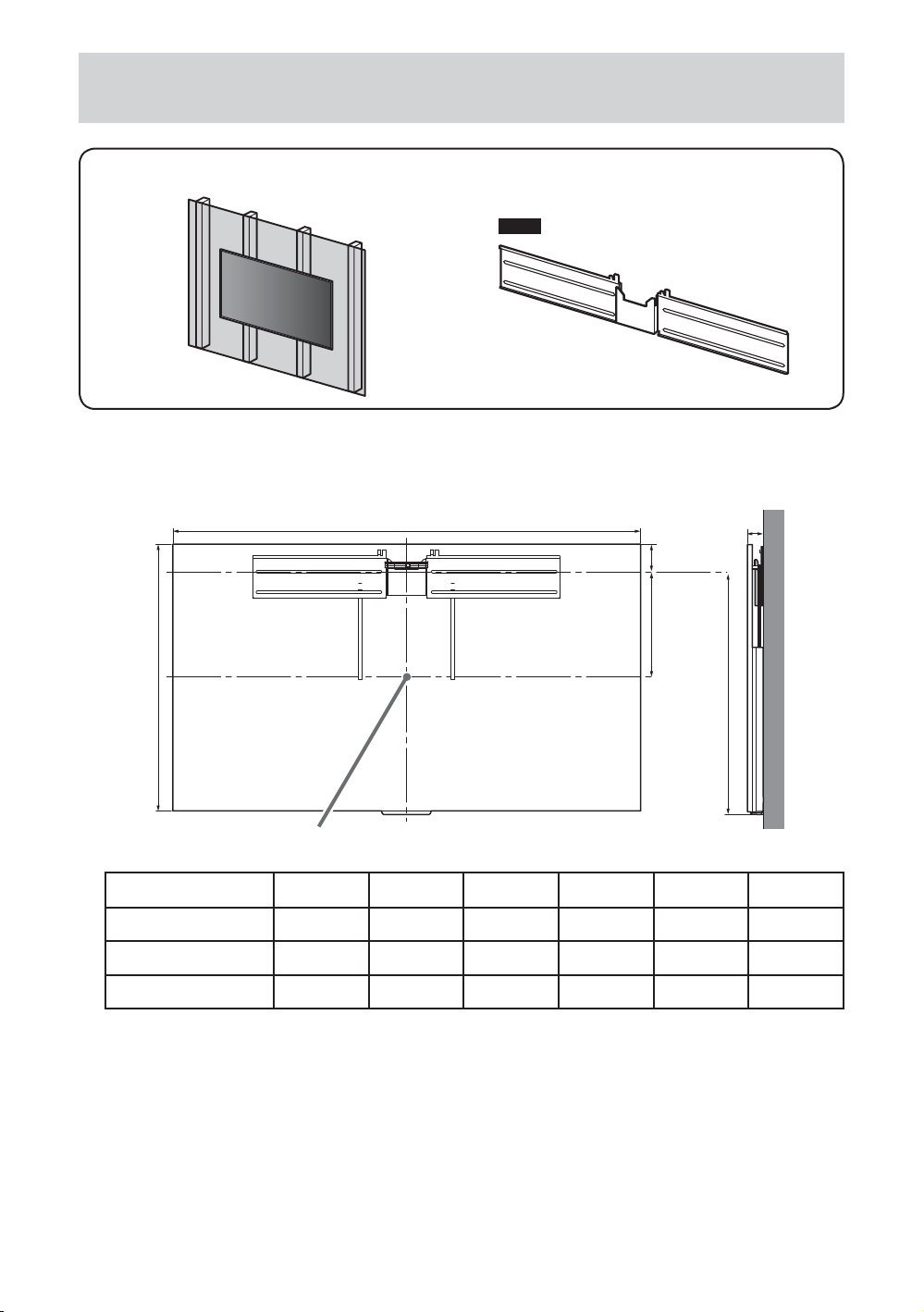
1 Decide on the installation location.
Make sure that the wall has enough space for the TV and is capable of supporting a weight of at
least four times that of the TV.
A
F
E
C
B
*
XBR
75X940D 1,672 960 387 871 59 90
65X930D 1,458 839 333 757 43 82
55X930D 1,239 717 271 634 43 83
TV installation dimensions table (mm)
(* Screen center point)
Figures in the table may differ slightly depending on the installation.
ABCDEF
D
US
10
Page 11
2
0
2
4
1
3
50
100
150
250
200
300
55’’
406 mm (16 inch) /
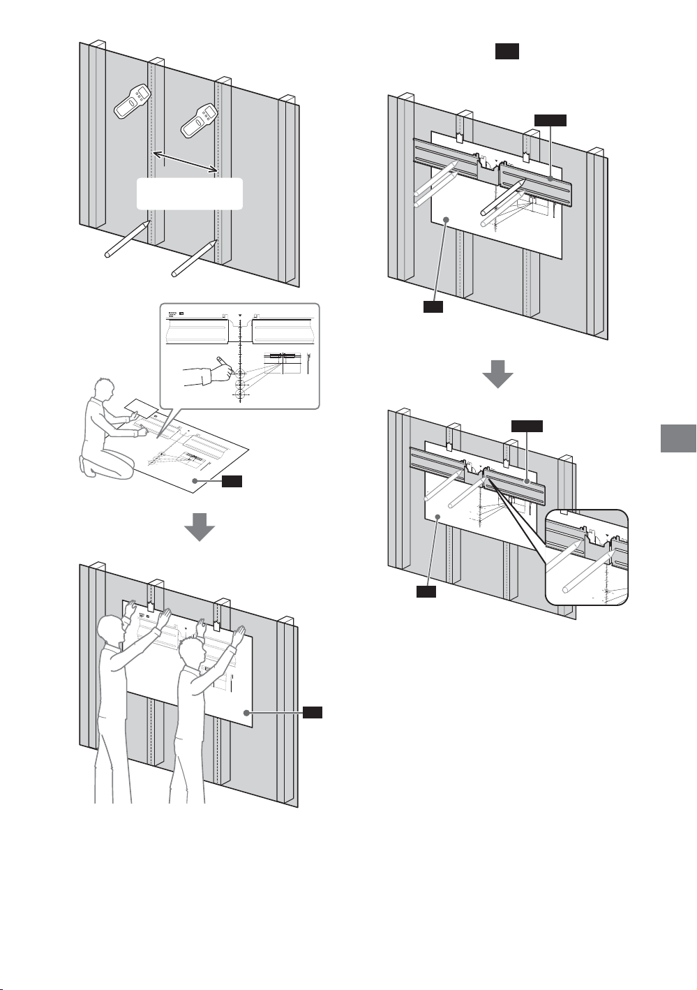
610 mm (24 inch)
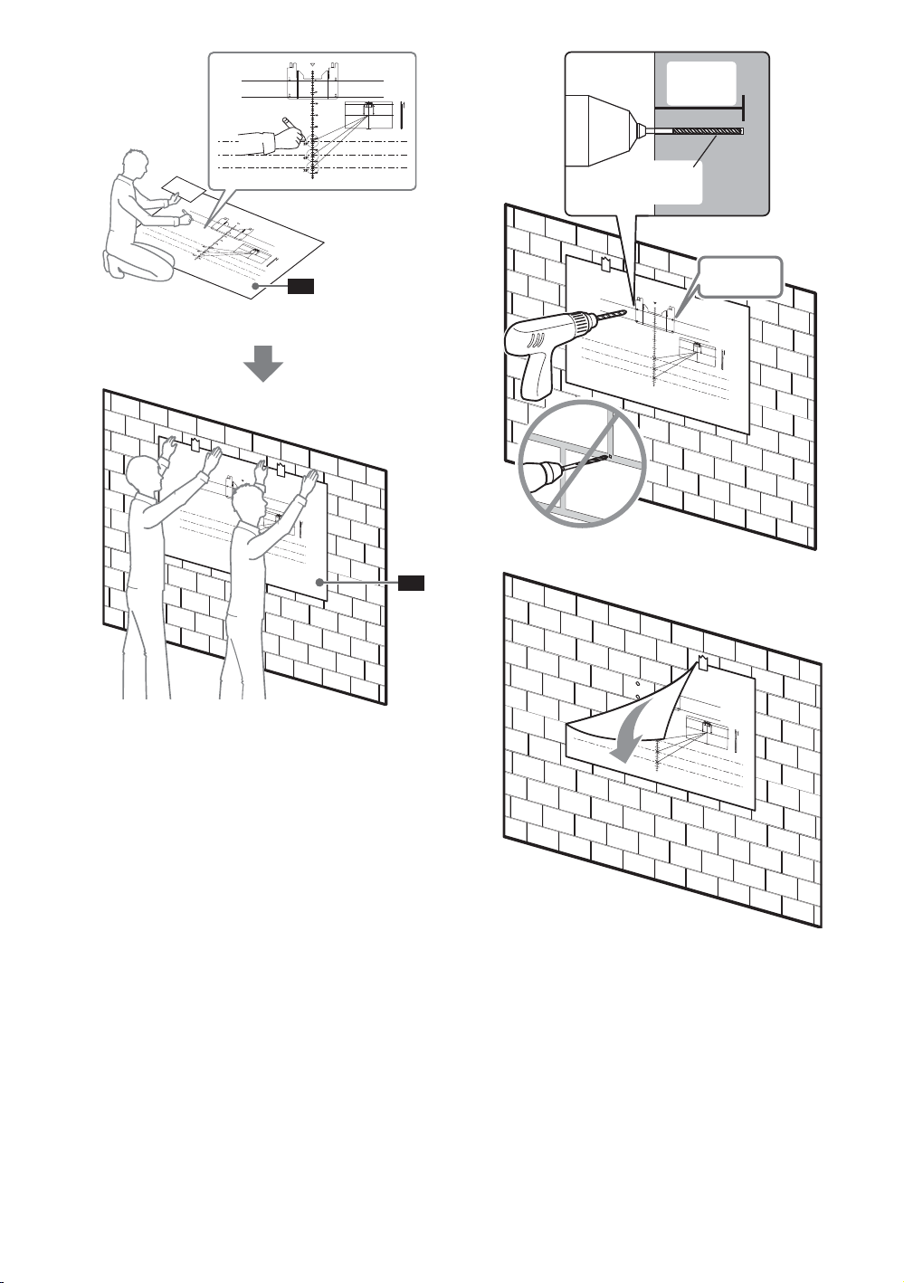
4 Poke through
with a pencil
TM
to make marks on the wall.
WM4
1
0
2
3
50
4
100
150
200
250
55’’
300
350
75’’
400
3
12inch11inch10inch 9inch 8inch 7inch 6inch 5inch 4inch 3inch 2inch 1inch 0 12inch11inch10inch9inch8inch7inch6inch5inch4inch3inch2inch1inch0
12inch
11inch10inch
9inch
8inch7inch
6inch
5inch4inch
3inch
2inch1inch
0
100
150
200
55
250
"
300
65
"
350
75
"
400
12inch11inch10inch9inch 8inch
7inch6inch 5inch 4inch
3inch
2inch 1inch0
TM
0
50
100
150
200
250
55
"
300
65
"
350
75
"
400
0
50
0
1inch
2inch
8inch7inch6inch5inch4inch3inch
9inch
10inch
12inch11inch
TM
1
3
WM4
US
0
2
50
4
100
150
200
250
55’’
300
350
75’’
400
TM
0
50
100
0
1inch
4inch3inch2inch
150
5inch
6inch
7inch
9inch8inch
11inch10inch
200
250
55
"
300
65
"
350
75
"
400
12inch
TM
US
11
Page 12
5
0
50
100
150
200
250
300
350
400
75
"
12inch11inch10inch
9inch
8inch7inch
6inch5inch
4inch
3inch 2inch
1inch
0
12inch
11inch
10inch9inch8inch7inch6inch
5inch
4inch3inch2inch
1inch
0
65
"
55
"
5.5 mm
(7/32 inch)
12inch
11inch10inch9inch 8inch
7inch6inch 5inch 4inch 3inch
2inch 1inch 0
0
50
100
150
200
250
55
"
300
65
"
350
75
"
400
75 mm
(3 inch)
3inch2inch1inch0
5inch4inch
6inch
8inch7inch
10inch9inch
11inch
12inch
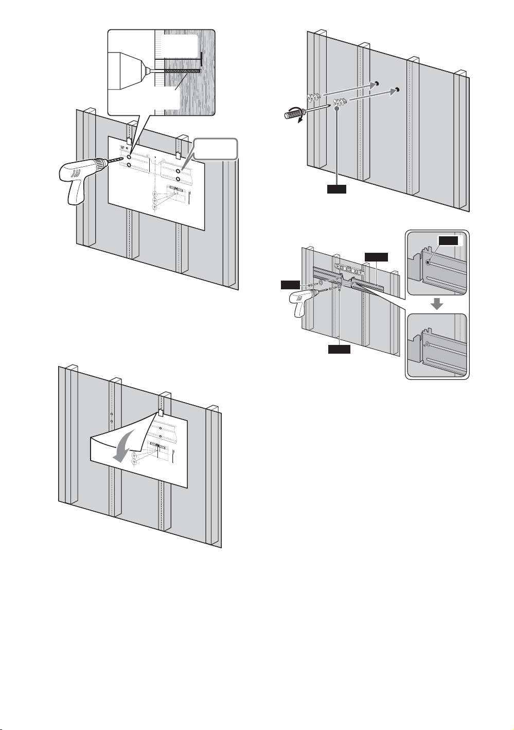
7
1, 2, 3, 4
WA2
Note
Be sure to drill into the center of wood
stud.
Pilot holes must be drilled to a depth of
75 mm (3 inch), using a 5.5 mm
(7/32 inch) diameter drill bit.
6
8
WA2
WM4
WS2
WW2
US
12
Page 13
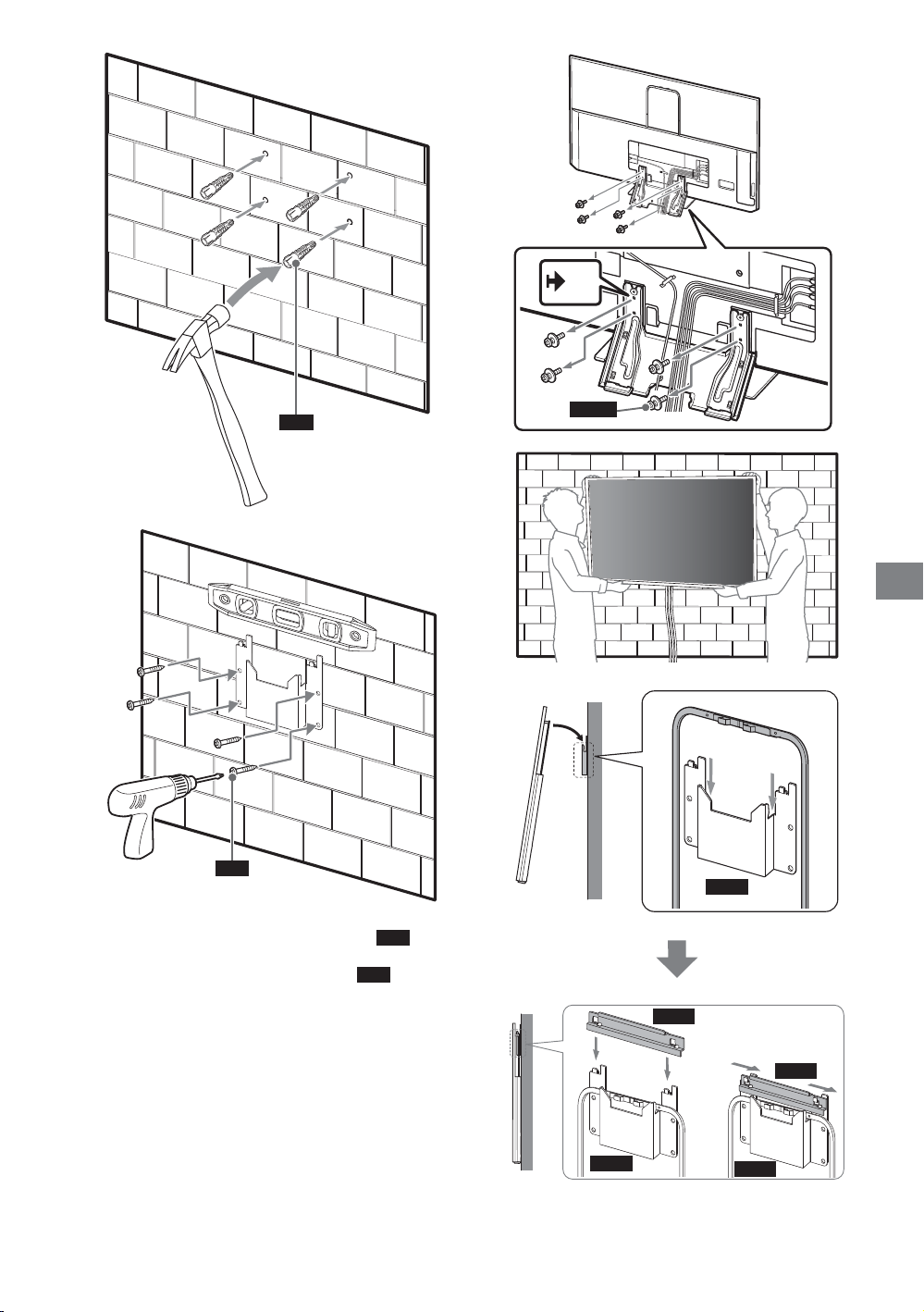
9
WS1
WW1
Precaution
Do not over-tighten the lag bolts
Improper tightening could reduce the
holding power of the lag bolts
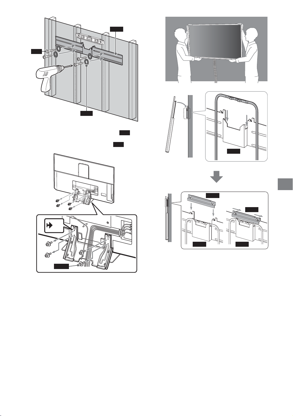
10
WM4
WS1
WS1
.
11
.
WM4
US
x 4
M5L12
WM1
WM1
WM4 WM4
13
US
Page 14
12
13
CL(S)
US
14
Page 15
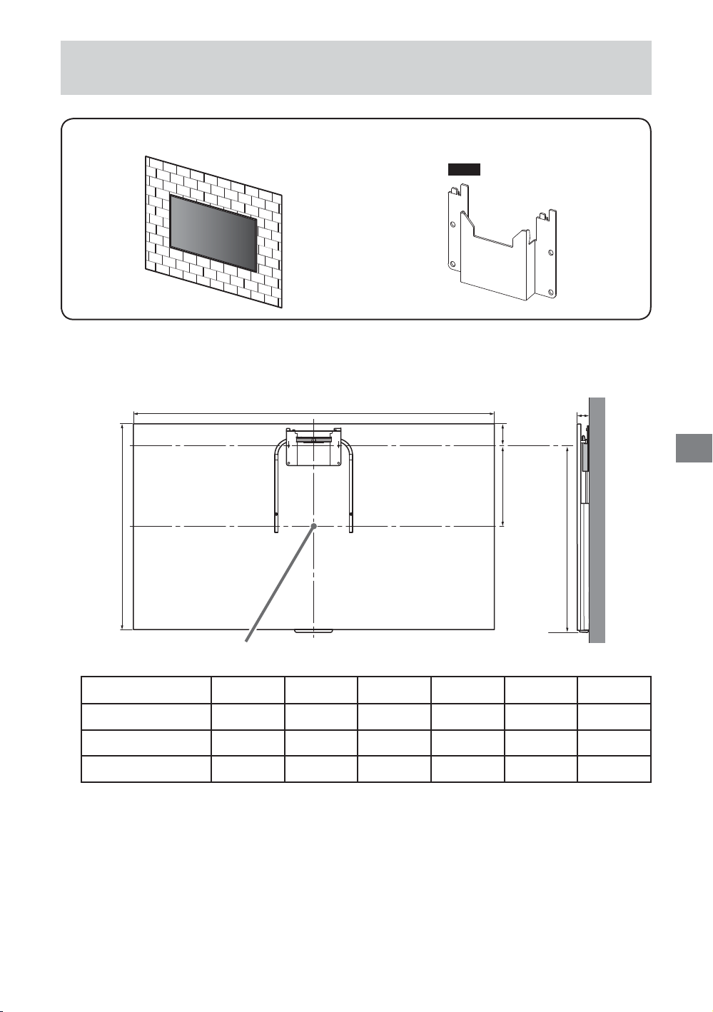
Attaching the Wall-Mount Bracket to the Solid Concrete or
Concrete Block
Solid Concrete or Concrete Block
WM2
1 Decide on the installation location.
Make sure that the wall has enough space for the TV and is capable of supporting a weight of at
least four times that of the TV.
A
E
F
C
B
*
XBR
75X940D 1,672 960 387 871 53 90
65X930D 1,458 839 333 757 37 82
55X930D 1,239 717 271 634 37 83
TV installation dimensions table (mm)
(* Screen center point)
Figures in the table may differ slightly depending on the installation.
ABCDEF
D
US
15
US
Page 16
2
0
2
4
1
3
50
100
150
250
200
300
350
400
75’’
65’’
55’’
3
75 mm
(3 inch)
10 mm
(3/8 inch)
TM
1
3
55’’
65’’
75’’
1
0
2
3
50
4
100
150
200
250
55’’
300
65’’
350
75’’
400
TM
4
1, 2, 3, 4
0
2
50
4
100
150
200
250
300
350
400
US
16
Page 17
5
7
x 4
WA1
6
WS1
Precaution
Do not over-tighten the lag bolts
Improper tightening could reduce the
holding power of the lag bolts
WS1
WS1
.
M5L12
8
US
WM2
.
WM2
WM1
WM1
WM2
US
17
Page 18

9
10
CL(S)
US
18
Page 19

Specifications
WM4
b
c
WM2
g
c
h
i
Dimension: (Approx.) (mm (inch))
a: 1,050 mm (41 3/8 inch)
b: 147 mm (5 7/8 inch)
c: 70 mm (2 7/8 inch)
d: 179 mm (7 1/8 inch)
e: 1,021 mm (40 1/4 inch)
f: 26 mm (1 1/16 inch)
g: 156 mm (6 1/4 inch)
h: 200 mm (7 7/8 inch)
i: 219 mm (8 5/8 inch)
j: 20 mm (13/16 inch)
a
d
e
j
f
US
Mass (base only): (Approx.)
3 kg / 6.6 lb.
WM4
1 kg / 2.2 lb.
WM2
Design and spe
cifications are subject to change without notice.
US
19
Page 20

Sécurité
Nous vous remercions d’avoir fait
l’acquisition de ce produit.
Note au consommateur
L’installation de ce produit nécessite une
certaine compétence. Veillez à confier
l’installation à un détaillant Sony ou à un
entrepreneur autorisé et portez une
attention particulière à la sécurité
pendant l’installation. Sony n’est pas
responsable des dommages ou
blessures provoquées par une mauvaise
manipulation ou une mauvaise
installation, ou par l’installation d’autres
produits que ceux précisés. Vos droits
légaux (le cas échéant) ne sont pas
affectés.
Aux détaillants Sony
L’installation de ce produit nécessite une
certaine compétence. Veillez à lire
attentivement le mode d’emploi pour
installer le produit en toute sécurité.
Sony n’est pas responsable des
dommages ou blessures provoquées par
une mauvaise manipulation ou une
mauvaise installation. Une fois
l’installation terminée, veuillez remettre
ce manuel d’installation au client.
Ce mode d’emploi indique comment
manipuler le produit correctement et
contient des précautions essentielles à
prendre pour éviter tout accident. Lisez
attentivement ce mode d’emploi et veillez à
utiliser le produit correctement. Conservez ce
mode d’emploi pour toute référence
ultérieure.
Les produits Sony sont conçus pour vous
offrir le maximum de sécurité. Toutefois, si
les produits sont utilisés de façon incorrecte,
ils peuvent entraîner des blessures graves en
provoquant un incendie ou l’électrocution,
ou encore la chute de l’appareil hors de son
support. Veillez à observer les consignes de
sécurité préconisées pour éviter de tels
accidents.
ATTENTION
Produits spécifiés
Ce support de fixation murale est conçu pour
l’utilisation avec les téléviseurs spécifiés.
Pour les téléviseurs, reportez-vous à leur
« Manuel de référence » pour vérifier qu’il est
possible d’utiliser le support de fixation
murale.
Note au consommateur
AVERTISSEMENT
Le non-respect des consignes suivantes
peut être fatal ou entraîner des blessures
graves en provoquant un incendie,
l’électrocution ou la chute de l’appareil.
Veillez à confier
l’installation à des
entrepreneurs autorisés
et à laisser les enfants à
l’écart pendant
l’installation.
Si le support de fixation murale ou le
téléviseur n’est pas installé correctement, les
accidents suivants peuvent se produire.
Veillez à confier l’installation à des
installateurs agréés.
Le téléviseur peut tomber et causer des
blessures graves comme des hématomes
ou des fractures.
Si le mur sur lequel le support de fixation
murale est fixé est instable, inégal ou non
perpendiculaire au sol, l’appareil risque de
tomber et de provoquer des blessures ou
des dommages matériels. Le mur doit
pouvoir supporter un poids équivalent à
au moins quatre fois celui du téléviseur.
(Pour connaître le poids du téléviseur,
reportez-vous à son mode d’emploi.)
Si l’installation du support de fixation
murale n’est pas assez solide, l’appareil
risque de tomber et de provoquer des
blessures ou des dommages matériels.
Veillez à confier le
déplacement ou le
démontage du téléviseur
à des entrepreneurs
autorisés.
Si des personnes autres que des installateurs
agréés transportent ou démontent le
téléviseur, celui-ci peut tomber et provoquer
des blessures ou des dommages matériels.
Deux personnes au moins doivent porter ou
démonter le téléviseur.
N’enlevez pas les vis, etc.,
après avoir installé le
téléviseur.
Dans ce cas, le téléviseur pourrait tomber et
provoquer des blessures ou des dommages
matériels.
N’effectuez pas de
modifications sur les
pièces du support de
fixation murale.
Dans ce cas, le support de fixation murale
pourrait tomber et provoquer des blessures
ou des dommages matériels.
N’installez pas un autre
équipement que le
produit spécifié.
Ce support de fixation murale est conçu pour
être utilisé avec les produits spécifiés
uniquement. Si vous installez un appareil
autre que ceux qui sont spécifiés, il pourrait
tomber ou se briser et provoquer des
blessures ou des dommages matériels.
N’appliquez aucune autre
charge que celle du
téléviseur sur le support
de fixation murale.
Ne secouez pas le
téléviseur vers la gauche/
droite, le haut/bas.
Dans ce cas, le téléviseur pourrait tomber et
provoquer des blessures ou des dommages
matériels.
Ne vous appuyez pas ou
ne vous suspendez pas
au téléviseur.
Ne vous appuyez pas sur le téléviseur et ne
vous y suspendez pas, car il risque de
tomber et de causer des blessures graves.
ATTENTION
Le non-respect des consignes suivantes
peut entraîner des blessures ou des
dommages matériels.
N’appliquez aucune force
excessive sur le produit
au cours de l’entretien ou
du nettoyage de
l’appareil.
N’exercez aucune pression excessive sur le
dessus du téléviseur. Dans ce cas, le
téléviseur pourrait tomber et provoquer des
blessures ou des dommages matériels.
Précautions
Si vous utilisez le téléviseur fixé au support
de fixation murale pendant une longue
période, le mur situé derrière le téléviseur
ou au-dessus de celui-ci peut se décolorer,
ou encore le papier peint peut se décoller,
selon le matériau du mur.
Les trous des vis restent apparents si vous
démontez le support de fixation murale
après son installation.
N’utilisez pas le support de fixation murale
à un endroit soumis à des vibrations
mécaniques.
Installation du
support de fixation
murale
Aux détaillants
Sony
AVERTISSEMENT
Les instructions suivantes sont destinées
uniquement aux détaillants Sony. Lisez
attentivement les consignes de sécurité
ci-dessus et accordez une attention
particulière à la sécurité lors de
l’installation, de l’entretien et de la
vérification de ce produit.
FR
2
Page 21

N’installez pas le support
de fixa
tion murale sur
des surfaces murales où
les coins ou les côtés du
téléviseur dépassent de
la surface murale.
N’installez pas le support de fixation murale
sur une surface verticale telle qu’une
colonne, où les coins ou les côtés du
téléviseur dépasseraient de la surface
murale. Si une personne ou un objet venait à
heurter le coin ou les côtés du téléviseur, ceci
risquerait de provoquer des blessures ou des
dommages matériels.
N’installez pas le
téléviseur sur ou endessous d’un climatiseur.
L’exposition prolongée du téléviseur à des
fuites d’eau ou à des courants d’air
provenant du climatiseur pourrait provoquer
un incendie, l’électrocution ou des
problèmes de fonctionnement du téléviseur.
Veillez à installer le
support de fixation
murale solidement au
mur en suivant les
instructions présentes
dans ce mode d’emploi.
Si une vis se desserre ou tombe, le support
de fixation murale peut tomber et provoquer
des blessures ou des pertes matérielles.
Assurez-vous d’utiliser des vis appropriées
pour le matériau du mur et d’installer
l’appareil solidement en utilisant la vis et les
douilles fournies.
Veillez à utiliser
correctement les vis et
les pièces de fixation
fournies conformément
aux instructions du
mode d’emploi. Si vous
utilisez d’autres
éléments de fixation, le
téléviseur pourrait
tomber et causer des
blessures corporelles
ou être endommagé.
Veillez à assembler
correctement les
supports en suivant la
procédure expliquée
dans ce mode d’emploi.
S’il manque des vis ou si elles sont
desserrées, le téléviseur pourrait tomber et
causer des blessures corporelles ou être
endommagé.
Veillez à serrer
fermement les vis dans la
position prévue.
Si vous oubliez, le téléviseur pourrait tomber
et causer des blessures corporelles ou être
endommagé.
Faites attention à ne pas
exposer le téléviseur à
des chocs pendant
l’installation.
Si le téléviseur subit des chocs, il pourrait
tomber ou se briser. Ceci pourrait causer des
blessures.
Veillez à installer le
téléviseur sur un mur plat
et perpendiculaire.
Dans le cas contraire, le téléviseur pourrait
tomber et provoquer des blessures.
Lorsque le téléviseur est
bien installé, fixez
correctement les câbles.
Si des personnes ou des objets s’accrochent
aux câbles, ceci risque de provoquer des
blessures ou d’endommager le téléviseur.
Veillez à ce que le cordon
d’alimentation CA ou le
câble de raccordement ne
soit pas coincé ni écrasé.
Si le cordon d’alimentation CA ou le câble de
raccordement est coincé entre l’appareil et le
mur, ou s’il est plié ou tordu, les conducteurs
internes peuvent être exposés et provoquer
un court-circuit ou une coupure électrique.
Un incendie ou l’électrocution pourrait en
résulter.
FR
FR
FR
3
Page 22

Table des matières
Avant de commencer .............................................................................................................................. 4
Quel est le type de matériau du mur? .........................................................................................................................4
Accessoires fournis ................................................................................................................................. 5
Outils requis ............................................................................................................................................. 5
Préparation pour l’installation du téléviseur .......................................................................................... 6
Fixation du support de déplacement latéral sur la Cloison Sèche avec Montants .........................10
Fixation du support de fixation murale au béton solide ou bloc de béton .....................................15
Spécifications ..........................................................................................................................................19
Avant de commencer
Commencez par vérifier le type de matériau du mur sur lequel vous souhaitez installer le téléviseur.
Le support de fixation murale varie selon le type de mur.
Quel est le type de matériau du mur?
Cloison sèche avec montants
Précautions
Épaisseur maximale de la cloison sèche :
16 mm (5/8 pouces).
Assurez-vous que la taille du montant en
bois interne est d’au moins 51 x 102 mm
(2 x 4 pouces) pour une charpente
commune ou 38 x 89 mm (1 1/2 x 3 1/2
pouces) pour une charpente nominale.
Laissez un espace horizontal minimal de
406 mm (16 pouces) entre les pièces de
fixation.
Utilisez le support de déplacement latéral.
Étapes
Fixez le support de table au téléviseur.
Fixez la barre en forme de U et les câbles
au téléviseur.
Installez le support de déplacement latéral
sur le mur.
Retirez le support de table du téléviseur.
Suspendez le téléviseur au mur.
Béton solide ou bloc de béton
Précautions
Fixez le support de fixation murale
directement sur le mur en béton solide.
Assurez-vous que l’épaisseur du mur en
béton solide est d’au moins 203 mm
(8 pouces).
Assurez-vous que la taille du bloc de béton
est d’au moins 203 x 203 x 406 mm
(8 x 8 x 16 pouces).
Utilisez le support de fixation murale.
Étapes
Fixez le support de table au téléviseur.
Fixez la barre en forme de U et les câbles
au téléviseur.
Installez le support de fixation murale sur
le mur.
Retirez le support de table du téléviseur.
Suspendez le téléviseur au mur.
FR
4
Page 23

Accessoires fournis
WM1 WM2 WM3 WM4 WM5
UB 75 UB 65 UB 55 TM
UB 75
UB 65
UB 55
M6L20
LIMITED WARRANTY
WS1
WS2
*1
8 mm x 60 mm
(11/32 pouces x 2 3/8 pouces)
4,8 mm x 32 mm
(7/32 pouces x 1 5/16 pouces)
Outils requis
*2
WW1
(4)
WA1
(2)
WW2
(4)
WA2
(4)
5,5 mm (7/32 pouces) 10 mm (3/8 pouces)
(2)
(2)
FR
FR
*1 Uniquement pour la cloison sèche avec montants
*2 Uniquement pour le béton solide ou bloc de béton
FR
5
Page 24

Préparation pour
l’installation du téléviseur
1 Placez le téléviseur sur le
support de table pour préparer
l’installation du support de
fixation murale.
M5L12
75
SN
2
SN
SB
65
55
SB
1
2
CC
CL(S)
SN
M5L12
x 4
FR
6
SC
Page 25

3
4
5
x 4
M5L12
Retirez les vis situées à l’arrière
6
du téléviseur.
7 Choisissez la barre en forme de
U correspondant à la taille de
votre téléviseur.
75
UB 75
UB 75
65
UB 65
UB 65
55
UB 55
UB 55
FR
FR
FR
7
Page 26

8 Fixez la barre en forme de U à l’arrière du téléviseur.
UB
75
M6L20
1.5 N∙m/1,5 N∙m
{15 kgf∙cm}
65 55
que vous
avez enlevées
précédemment
1.5 N∙m/1,5 N∙m
{15 kgf∙cm}
FR
8
Page 27

9
WM3
*
WM5
* Uniquement pour le support de déplacement latéral
10 Raccordez et regroupez les câbles.
12
3
FR
FR
WM4
9
FR
Page 28

Fixation du support de déplacement latéral sur la Cloison
Sèche avec Montants
Cloison sèche avec montants
WM4
1 Décidez de l’emplacement d’installation.
Assurez-vous que le mur offre suffisamment d’espace pour le téléviseur et qu’il peut supporter
un poids équivalent à au moins quatre fois celui du téléviseur.
A
F
E
C
B
*
XBR
75X940D 1 672 960 387 871 59 90
65X930D 1 458 839 333 757 43 82
55X930D 1 239 717 271 634 43 83
Tableau des dimensions d’installation des téléviseurs (mm)
(* Point central de l’écran)
Les chiffres repris dans le tableau peuvent varier légèrement selon l’installation.
ABCDEF
D
FR
10
Page 29

2
0
2
4
1
3
50
100
150
250
200
300
55’’
406 mm (16 pouces) /
610 mm (24 pouces)
4 Percez le
avec un crayon
TM
pour marquer le mur.
1
0
3
50
100
150
200
250
55’’
300
350
75’’
400
WM4
2
4
3
12inch11inch10inch 9inch 8inch 7inch 6inch 5inch 4inch 3inch 2inch 1inch 0 12inch11inch10inch9inch8inch7inch6inch5inch4inch3inch2inch1inch0
12inch
11inch10inch
9inch
8inch7inch
6inch
5inch4inch
3inch
2inch1inch
0
100
150
200
55
250
"
300
65
"
350
75
"
400
12inch11inch10inch9inch 8inch
7inch6inch 5inch 4inch
3inch
2inch 1inch0
TM
0
50
100
150
200
250
55
"
300
65
"
350
75
"
400
0
50
0
1inch
2inch
8inch7inch6inch5inch4inch3inch
9inch
10inch
12inch11inch
TM
1
3
WM4
0
2
50
4
100
150
200
250
55’’
300
350
75’’
400
FR
FR
TM
0
50
100
0
1inch
4inch3inch2inch
150
5inch
6inch
7inch
9inch8inch
11inch10inch
200
250
55
"
300
65
"
350
75
"
400
12inch
TM
FR
11
Page 30

5
0
50
100
150
200
250
300
350
400
75
"
12inch11inch10inch
9inch8inch 7inch 6inch
5inch
4inch
3inch 2inch
1inch 0
12inch11inch10inch9inch8inch7inch
6inch5inch4inch
3inch
2inch1inch0
65
"
55
"
5,5 mm
(7/32 pouces)
12inch
11inch10inch9inch 8inch
7inch6inch 5inch
4inch3inch
2inch 1inch 0
55
"
65
"
75
"
75 mm
(3 pouces)
0
50
100
4inch3inch2inch1inch0
150
6inch5inch
7inch
200
250
300
350
400
7
1, 2, 3, 4
8inch
10inch9inch
11inch
12inch
WA2
Remarque
Assurez-vous de percer au centre du
montant en bois.
Des avant-trous doivent être percés à
une profondeur de 75 mm (3 pouces), à
l’aide d’une mèche de 5,5 mm
(7/32 pouces) de diamètre.
6
8
WA2
WM4
WS2
WW2
FR
12
Page 31

9
WS1
WW1
Précautions
Ne serrez pas excessivement les
tirefonds
pourrait réduire la capacité de maintien
des tirefonds
. Un serrage incorrect
WS1
.
WS1
10
11
WM4
WM4
x 4
M5L12
WM1
WM4 WM4
WM1
FR
FR
13
FR
Page 32

12
13
CL(S)
FR
14
Page 33

Fixation du support de fixation murale au béton solide ou
bloc de béton
Béton solide ou bloc de béton
WM2
1 Décidez de l’emplacement d’installation.
Assurez-vous que le mur offre suffisamment d’espace pour le téléviseur et qu’il peut supporter
un poids équivalent à au moins quatre fois celui du téléviseur.
A
F
E
C
B
*
XBR
75X940D 1 672 960 387 871 53 90
65X930D 1 458 839 333 757 37 82
55X930D 1 239 717 271 634 37 83
Tableau des dimensions d’installation des téléviseurs (mm)
(* Point central de l’écran)
Les chiffres repris dans le tableau peuvent varier légèrement selon l’installation.
ABCDEF
D
FR
FR
15
FR
Page 34

2
0
2
4
1
3
50
100
150
250
200
300
350
400
75’’
65’’
55’’
3
75 mm
(3 pouces)
10 mm
(3/8 pouces)
TM
1
3
55’’
65’’
75’’
1
0
2
3
50
4
100
150
200
250
55’’
300
65’’
350
75’’
400
TM
4
1, 2, 3, 4
0
2
50
4
100
150
200
250
300
350
400
FR
16
Page 35

5
7
x 4
WA1
6
WS1
Précautions
Ne serrez pas excessivement les
tirefonds
pourrait réduire la capacité de maintien
des tirefonds
. Un serrage incorrect
WS1
.
WS1
M5L12
8
FR
FR
WM2
WM1
WM2
WM1
WM2
FR
17
Page 36

9
10
CL(S)
FR
18
Page 37

Spécifications
WM4
b
c
WM2
g
c
h
i
Dimensions : (Environ) (mm (pouces))
a : 1 050 mm (41 3/8 pouces)
b : 147 mm (5 7/8 pouces)
c : 70 mm (2 7/8 pouces)
d : 179 mm (7 1/8 pouces)
e : 1 021 mm (40 1/4 pouces)
f : 26 mm (1 1/16 pouces)
g : 156 mm (6 1/4 pouces)
h : 200 mm (7 7/8 pouces)
i : 219 mm (8 5/8 pouces)
j : 20 mm (13/16 pouces)
a
d
e
j
f
FR
FR
Poids (base seulement) : (Environ)
3 kg / 6,6 lb.
WM4
1 kg / 2,2 lb.
WM2
La c
onception et les spécifications sont susceptibles d’être modifiées sans préavis.
FR
19
Page 38

Seguridad
Muchas gracias por la adquisición de este
producto.
Para los clientes
Para la instalación de este producto se
requieren conocimientos y experiencia
suficientes. Asegúrese de obtener
servicios de instalación de distribuidores
o contratistas autorizados por Sony y de
prestar especial atención a la seguridad
durante la instalación. Sony no será
responsable de daños o lesiones
ocacionadas por el manejo indebido o
instalación incorrecta ni de la instalación
de cualquier otro producto distinto al
especificado. Sus derechos legales (si
existe alguno) no son afectados.
Para distribuidores de
Sony
Para la instalación de este producto se
requieren conocimientos y experiencia
suficientes. Asegúrese de leer
completamente este manual de
instrucciones para realizar el trabajo de
instalación de manera segura. Sony no
será responsable de daños o lesiones
ocacionadas por el manejo indebido o
instalación incorrecta. Entregue este
manual al cliente después de la
instalación.
Este manual de instrucciones muestra la
manera correcta de manipular el producto,
así como precauciones importantes
necesarias para evitar accidentes. Lea
detenidamente este manual y utilice el
producto correctamente. Conserve este
manual para poder consultarlo en el futuro.
Los productos de Sony están diseñados
pensando en la seguridad. Sin embargo, si
los productos se utilizan incorrectamente,
pueden producirse lesiones graves a causa
de un incendio o una descarga, o al volcarse
o caerse el producto. Para evitar tales
accidentes, asegúrese de observar las
precauciones de seguridad.
PRECAUCIÓN
Productos especificados
El soporte de montaje mural está diseñado
para utilizar con los TV especificados en el
producto. Consulte el “Guía de referencia”
del TV para confirmar que el soporte de
montaje mural pueda utilizarse.
Para los clientes
ADVERTENCIA
Si no se tienen en cuenta las siguientes
precauciones, existe el peligro de sufrir
lesiones graves o incluso de muerte a
raíz de un incendio o una descarga
eléctrica, o a causa de que el producto
se caiga.
Asegúrese de obtener
servicios de instalación
de contratistas
autorizados y de
mantener alejados a los
niños pequeños durante
la instalación.
Si el soporte de montaje mural o el televisor
no están instalados correctamente, pueden
ocurrir los accidentes siguientes. Asegúrese
de que la instalación la llevan a cabo
contratistas autorizados.
El televisor podría caerse y provocar
lesiones graves como contusiones o
fracturas.
Si la pared en la que se instala el soporte
de montaje mural es inestable, desigual o
no es perpendicular al suelo, la unidad
puede caerse y provocar daños personales
o materiales. La pared debe ser capaz de
soportar un peso de al menos cuatro veces
el peso del televisor.
(Consulte las instrucciones de su televisor
para obtener información sobre el peso de
éste.)
Si la instalación del soporte de montaje
mural en la pared no es lo suficientemente
resistente, es posible que la unidad se
caiga y provoque daños personales o
materiales.
Asegúrese de obtener
servicios de traslado o
desmontaje del TV de
contratistas autorizados.
Si otras personas que no son contratistas
autorizados llevan a cabo el transporte o el
desmontaje del televisor, éste puede caerse
y provocar daños personales y materiales.
Asegúrese de que transportan o desmontan
el televisor dos o más personas.
No quite tornillos, etc.,
después de montar el TV.
Si lo hace, el televisor puede caerse y
provocar daños personales o materiales.
No haga alteraciones a
las partes del soporte de
montaje mural.
Si lo hace, el soporte de montaje mural
puede caerse y provocar daños personales o
materiales.
No instale ningún equipo
diferente al producto
especificado.
Este soporte de montaje mural se ha
diseñado para utilizarse sólo con el producto
especificado. Si monta un equipo distinto del
especificado, puede caerse o romperse y
provocar daños personales o materiales.
No ponga ninguna carga
diferente a la del TV en el
soporte de montaje
mural.
No sacuda el televisor
hacia la izquierda, la
derecha, arriba o abajo.
Si lo hace, el televisor puede caerse y
provocar daños personales o materiales.
No se apoye ni se
cuelgue del TV.
No se apoye en el televisor ni se cuelgue de
éste, ya que podría caerle encima y
provocarle lesiones graves.
PRECAUCIÓN
Si no se tienen en cuenta las
precauciones siguientes, podrían
producirse daños personales o
materiales.
No manipule el producto
con fuerza excesiva
cuando realice su
limpieza o
mantenimiento.
No aplique fuerza excesiva en la parte
superior del televisor. Si lo hace, el televisor
puede caerse y provocar daños personales o
materiales.
Precauciones
Si utiliza el televisor instalado en el soporte
de montaje mural durante un largo
período de tiempo, es posible que la pared
que quede detrás o encima del televisor se
descolore o que, si la pared está
empapelada, se despegue el papel,
dependiendo del material de la pared.
Si se quita el soporte de montaje mural
después de haber estado instalado en la
pared, quedarán los orificios de los
tornillos.
No utilice el soporte de montaje mural en
un lugar que esté sujeto a la vibración
mecánica.
Instalación del
soporte del montaje
mural
Para distribuidores de
Sony
ADVERTENCIA
Las siguientes instrucciones son
únicamente para distribuidores de Sony.
Asegúrese de leer las precauciones de
seguridad descritas anteriormente y
preste especial atención a la seguridad
durante la instalación, el mantenimiento
y la comprobación de este producto.
ES
2
Page 39

No instale el soporte de
aje mural sobre
mont
superficies de paredes
donde las esquinas o los
costados del TV
sobresalgan de la
superficie de la pared.
No instale el soporte de montaje mural en
superficies de paredes, tales como una
columna, en las que puedan sobresalir las
esquinas o los lados del televisor. Si una
persona o un objeto se golpea con la
esquina o el lado saliente del televisor,
pueden producirse daños personales o
materiales.
No instale el TV sobre o
debajo de un equipo de
aire acondicionado.
Si el televisor queda expuesto a goteo de
agua o corriente de aire procedentes del
aparato de aire acondicionado durante
mucho tiempo, podría producirse un
incendio, una descarga eléctrica o un fallo de
funcionamiento.
Asegúrese de instalar el
soporte de montaje
mural firmemente a la
pared siguiendo las
instrucciones de este
manual de instrucciones.
Si alguno de los tornillos se deja flojo o se
cae, es posible que se caiga el soporte de
montaje mural y ocasione lesiones o daños a
la propiedad. Asegúrese de utilizar los
tornillos adecuados para el material de la
pared e instale la unidad de forma segura,
utilizando los tornillos y anclajes
suministrados.
Asegúrese de utilizar
correctamente los
tornillos y las piezas de
sujeción suministrados
siguiendo las
instrucciones que se
describen en este
manual. Si utiliza
artículos sustitutivos,
el televisor podría
caerse y dañarse o
provocar daños
personales.
Asegúrese de ensamblar
el soporte correctamente
siguiendo el
procedimiento
establecido explicado en
este manual de
instrucciones.
Si alguno de los tornillos queda suelto o se
desprende, el televisor podría caerse y
dañarse o provocar daños personales.
Asegúrese de apretar los
tornillos firmemente en
la posición específica.
De lo contrario, el televisor podría caerse y
dañarse o provocar daños personales.
Tenga cuidado de no
someter el TV a
descargas eléctricas
durante la instalación.
Si el televisor recibe algún golpe, puede
caerse o romperse. Tales percances podrían
causar heridas personales.
Asegúrese de instalar el
TV en una pared que sea
perpendicular y plana.
De lo contrario, el televisor podría caerse y
provocar daños personales.
Después de instalar el TV
correctamente, fije los
cables apropiadamente.
Si alguna persona u objeto se enreda con los
cables, correrá el peligro de sufrir heridas
personales o de dañarse el televisor.
Evite que el cable de
alimentación de ca o el
cable de conexión
queden atrapados.
Si el cable de alimentación de ca o el cable
de conexión quedan atrapados entre la
unidad y la pared o si se doblan o tuercen
con fuerza, es posible que los conductores
internos queden expuestos y que provoquen
un cortocircuito o corte eléctrico. Esto podría
originar un incendio o producir descargas
eléctricas.
ES
ES
ES
3
Page 40

Tabla de contenido
Antes de comenzar .................................................................................................................................. 4
¿De qué está hecha la pared? ...................................................................................................................................... 4
Artículos suministrados ........................................................................................................................... 5
Herramientas necesarias ......................................................................................................................... 5
Preparación de la instalación del TV ....................................................................................................... 6
Una el soporte de desplazamiento lateral a la Pared de Mampostería con Pernos de tope ..........10
Coloque el soporte de montaje mural al concreto sólido o al bloque de concreto ........................ 15
Especificaciones ......................................................................................................................................19
Antes de comenzar
Primero compruebe el tipo de pared para instalar el TV.
El soporte de montaje mural varía en función del tipo de la pared.
¿De qué está hecha la pared?
Pared de mampostería con pernos de tope
Precauciones
Grosor máximo de la mampostería:
16 mm.
Asegúrese de que el tamaño del perno de
tope para madera interno sea de al menos
51 x 102 mm para el común o 38 x 89 mm
para el nominal.
Mantenga un espacio horizontal mínimo de
406 mm entre los sujetadores.
Utilice el soporte de desplazamiento lateral.
Pasos a seguir
Conecte el soporte de sobremesa del TV.
Coloque la barra en forma de U y los
cables al TV.
Instale el soporte de desplazamiento
lateral en la pared.
Separe la mesa auxiliar del TV.
Cuelgue el TV en la pared.
Concreto sólido o bloque de concreto
Precauciones
Monte el soporte de montaje mural
directamente en la pared de concreto
sólido.
Asegúrese de que el grosor de la pared de
concreto sólido sea de al menos 203 mm.
Asegúrese de que el tamaño de cada
bloque de concreto sea de al menos
203 x 203 x 406 mm.
Utilice el soporte de montaje mural.
Pasos a seguir
Conecte el soporte de sobremesa del TV.
Coloque la barra en forma de U y los
cables al TV.
Instale el soporte de montaje mural en la
pared.
Separe la mesa auxiliar del TV.
Cuelgue el TV en la pared.
ES
4
Page 41

Artículos suministrados
WM1 WM2 WM3 WM4 WM5
UB 75 UB 65 UB 55 TM
UB 75
UB 65
UB 55
M6L20
LIMITED WARRANTY
WS1
WW1
WW2
8 mm x 60 mm
WS2
(4)
WA1
4,8 mm x 32 mm
(2)
(4)
(4)
WA2
(2)
ES
ES
(2)
Herramientas necesarias
*1
5,5 mm 10 mm
*2
*1 Solo para pared de mampostería con pernos de tope
*2 Solo para concreto sólido o bloque de concreto
ES
5
Page 42

Preparación de la
instalación del TV
1 Coloque el TV sobre el soporte
de sobremesa para preparar la
instalación del soporte de
montaje mural.
M5L12
75
SN
2
SN
SB
65
55
SB
1
2
CC
CL(S)
SN
M5L12
x 4
ES
6
SC
Page 43

3
4
5
x 4
M5L12
Quite los tornillos de la parte
6
trasera del TV.
7 Seleccione la barra en forma de
U según el tamaño de su TV.
75
UB 75
UB 75
65
UB 65
UB 65
55
UB 55
UB 55
ES
ES
ES
7
Page 44

8 Coloque la barra en forma de U a la parte trasera del TV.
UB
75
M6L20
1.5 N∙m/1,5 N∙m
{15 kgf∙cm}
65 55
retirados
previamente
1.5 N∙m/1,5 N∙m
{15 kgf∙cm}
ES
8
Page 45

9
WM3
*
WM5
* Solo para el soporte de desplazamiento lateral
10 Conecte y agrupe los cables.
12
3
WM4
ES
ES
9
ES
Page 46

Una el soporte de desplazamiento lateral a la Pared de
Mampostería con Pernos de tope
Pared de mampostería con pernos de tope
WM4
1 Decida dónde va a realizar la instalación.
Asegúrese de que la pared tenga espacio suficiente para el TV y pueda soportar un peso que
represente al menos cuatro veces el del TV.
A
F
E
C
B
*
XBR
75X940D 1.672 960 387 871 59 90
65X930D 1.458 839 333 757 43 82
55X930D 1.239 717 271 634 43 83
Tabla de dimensiones para la instalación del TV (mm)
(* Punto central de la pantalla)
Las cifras de la tabla pueden variar levemente según el tipo de instalación.
ABCDEF
D
ES
10
Page 47

2
0
2
4
1
3
50
100
150
250
200
300
55’’
406 mm / 610 mm
4 Pique con un lápiz a través de
para hacer marcas en la
TM
pared.
WM4
1
0
2
3
50
4
100
150
200
250
55’’
300
350
75’’
400
3
12inch11inch10inch 9inch 8inch 7inch 6inch 5inch 4inch 3inch 2inch 1inch 0 12inch11inch10inch9inch8inch7inch6inch5inch4inch3inch2inch1inch0
12inch
11inch10inch
9inch
8inch7inch
6inch
5inch4inch
3inch
2inch1inch
0
100
150
200
55
250
"
300
65
"
350
75
"
400
12inch11inch10inch9inch 8inch
7inch6inch 5inch 4inch
3inch
2inch 1inch0
0
50
100
150
200
250
55
"
300
65
"
350
75
"
400
0
50
0
1inch
2inch
8inch7inch6inch5inch4inch3inch
9inch
10inch
12inch11inch
TM
TM
WM4
1
0
2
3
50
4
100
150
200
250
55’’
300
350
75’’
400
ES
ES
TM
0
50
100
0
1inch
4inch3inch2inch
150
5inch
6inch
7inch
9inch8inch
11inch10inch
200
250
55
"
300
65
"
350
75
"
400
12inch
TM
ES
11
Page 48

5
0
50
100
150
200
250
300
350
400
75
"
12inch11inch10inch
9inch
8inch7inch
6inch5inch
4inch
3inch 2inch
1inch 0
12inch
11inch
10inch9inch8inch7inch6inch5inch
4inch3inch2inch
1inch
0
65
"
55
"
12inch
11inch10inch9inch 8inch
5,5 mm
7inch6inch 5inch
4inch3inch
2inch 1inch 0
0
50
100
150
200
250
55
"
300
65
"
350
75
"
400
75 mm
4inch3inch2inch1inch0
6inch5inch
7inch
8inch
10inch9inch
11inch
12inch
7
1, 2, 3, 4
WA2
Nota
Asegúrese de perforar en el centro del
perno de tope para madera.
Los agujeros piloto deben perforarse a
una profundidad de 75 mm, utilizando
una broca de 5,5 mm.
6
8
WA2
WM4
WS2
WW2
ES
12
Page 49

9
WS1
WW1
Precauciones
No ajuste demasiado los pernos de
fijación
reducir la capacidad de retención del
perno de fijación
. El ajuste inadecuado puede
WS1
.
WS1
10
11
WM4
WM4
x 4
M5L12
WM1
WM4 WM4
WM1
ES
ES
13
ES
Page 50

12
13
CL(S)
ES
14
Page 51

Coloque el soporte de montaje mural al concreto sólido o
al bloque de concreto
Concreto sólido o bloque de concreto
WM2
1 Decida dónde va a realizar la instalación.
Asegúrese de que la pared tenga espacio suficiente para el TV y pueda soportar un peso que
represente al menos cuatro veces el del TV.
A
F
E
C
B
*
XBR
75X940D 1.672 960 387 871 53 90
65X930D 1.458 839 333 757 37 82
55X930D 1.239 717 271 634 37 83
Tabla de dimensiones para la instalación del TV (mm)
(* Punto central de la pantalla)
Las cifras de la tabla pueden variar levemente según el tipo de instalación.
ABCDEF
D
ES
ES
15
ES
Page 52

2
0
2
4
1
3
50
100
150
250
200
300
350
400
75’’
65’’
55’’
3
75 mm
10 mm
TM
1
3
55’’
65’’
75’’
1
0
2
3
50
4
100
150
200
250
55’’
300
65’’
350
75’’
400
TM
4
1, 2, 3, 4
0
2
50
4
100
150
200
250
300
350
400
ES
16
Page 53

5
7
x 4
WA1
6
WS1
Precauciones
No ajuste demasiado los pernos de
fijación
reducir la capacidad de retención del
perno de fijación
. El ajuste inadecuado puede
WS1
.
WS1
M5L12
8
ES
ES
WM2
WM1
WM2
WM1
WM2
ES
17
Page 54

9
10
CL(S)
ES
18
Page 55

Especificaciones
WM4
b
c
WM2
g
c
h
i
Dimensiones: (Aprox.) (mm)
a: 1.050 mm
b: 147 mm
c: 70 mm
d: 179 mm
e: 1.021 mm
f: 26 mm
g: 156 mm
h: 200 mm
i: 219 mm
j: 20 mm
a
d
e
j
f
ES
ES
Peso (solo de la base): (Aprox.)
3 kg
WM4
1 kg
WM2
El diseño y las espe
cificaciones pueden cambiar sin aviso.
ES
19
Page 56

http://www.sony.net/
4-588-644-13(1)
© 2016 Sony Corporation Printed in China
 Loading...