

Page 1
To Customers and Sony Dealers
Wall-Mount Bracket
C-644-100-12(1)
Installation Manual
Manuel d’installation
Manual de instalación
GB
FR
ES
SU-WL500
© 2017 Sony Corporation
Page 2
Thank you for purchasing this product.
To Cus tomer s
Sufficient expertise is required for installing this
product. Be sure to subcontract the installation to
Sony dealers or licensed contractors and pay
special attention to safety during the installation.
Sony is not liable for any damages or injury
caused by mishandling or improper installation, or
installing any other than the specified product.
Your Statutory Rights (if any) are not affected.
WARNING
If the safety precautions are not observed or the
product is used incorrectly, it may result in serious
injury or fire.
This manual shows the correct handling of the
product and important precautions necessary to
prevent accidents. Be sure to read this manual
thoroughly and use the product correctly. Keep this
manual available for future reference.
To Sony dealers
Sufficient expertise is required for installing this
product. Be sure to read this manual thoroughly to do
the installation work safely. Sony is not liable for any
damages or injury caused by mishandling or
improper installation. Please give this manual to the
customer after installation.
CAUTION
Specified products
The following products are subject to change
without notice, may be out of stock, or
discontinued.
Some models may not be available in certain
regions.
XBR-75X900E
XBR-65X900E
XBR-55X900E
XBR-49X900E
XBR-75X850E
XBR-65X850E
XBR-55X800E
XBR-49X800E
LCD Color TV
XBR-43X800E
KD-75X9000E
KD-65X9000E
KD-55X9000E
KD-49X9000E
KD-75X8500E
KD-65X8500E
KD-55X8500E
KD-49X8000E
KD-43X8000E
On Safety
Products by Sony are designed with safety in mind. If
the products are used incorrectly, however, it may
result in a serious injury through fire, electric shock,
the product toppling over, or the product dropping.
Be sure to observe the precautions for safety to
prevent such accidents.
2 (GB)
Page 3
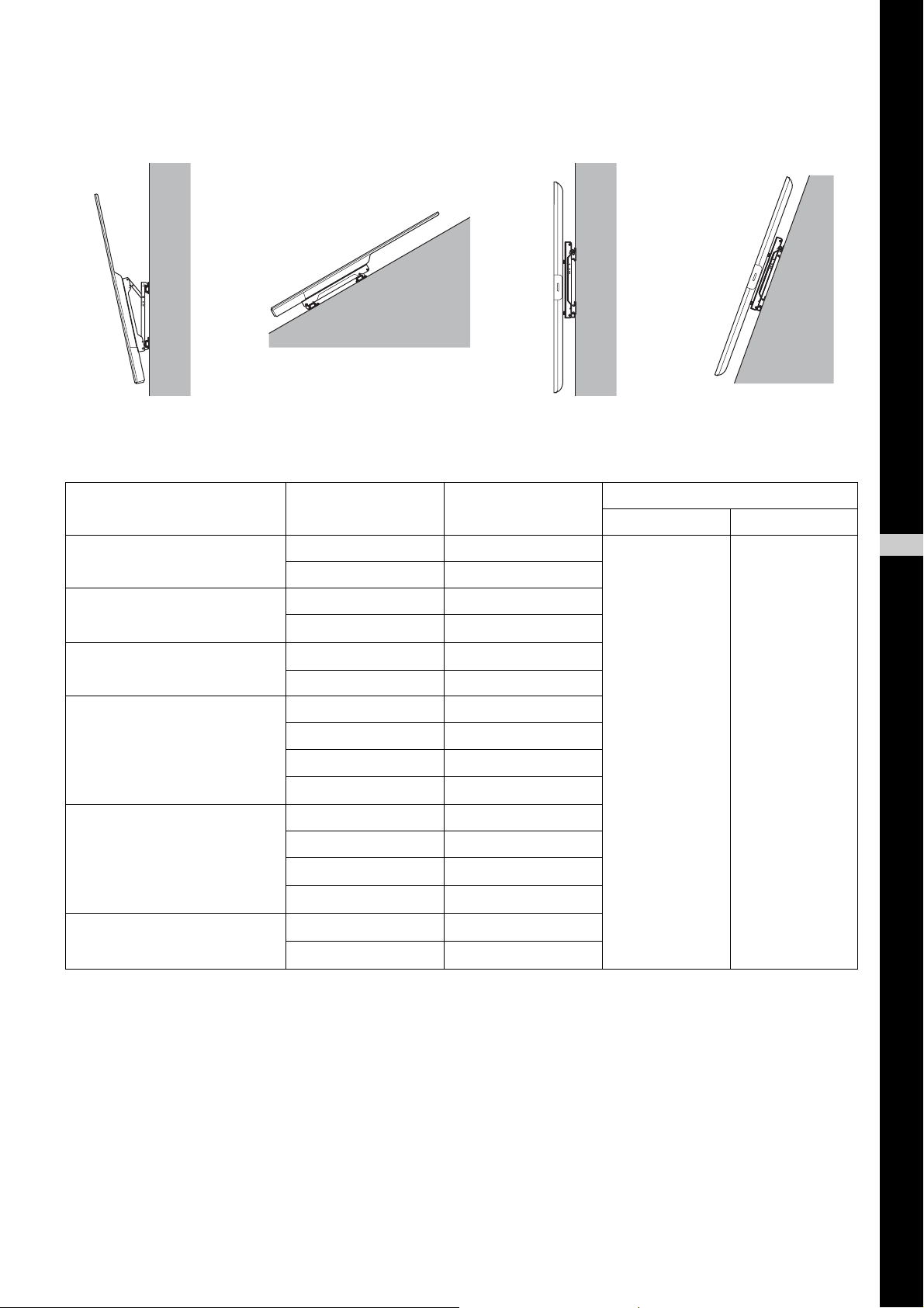
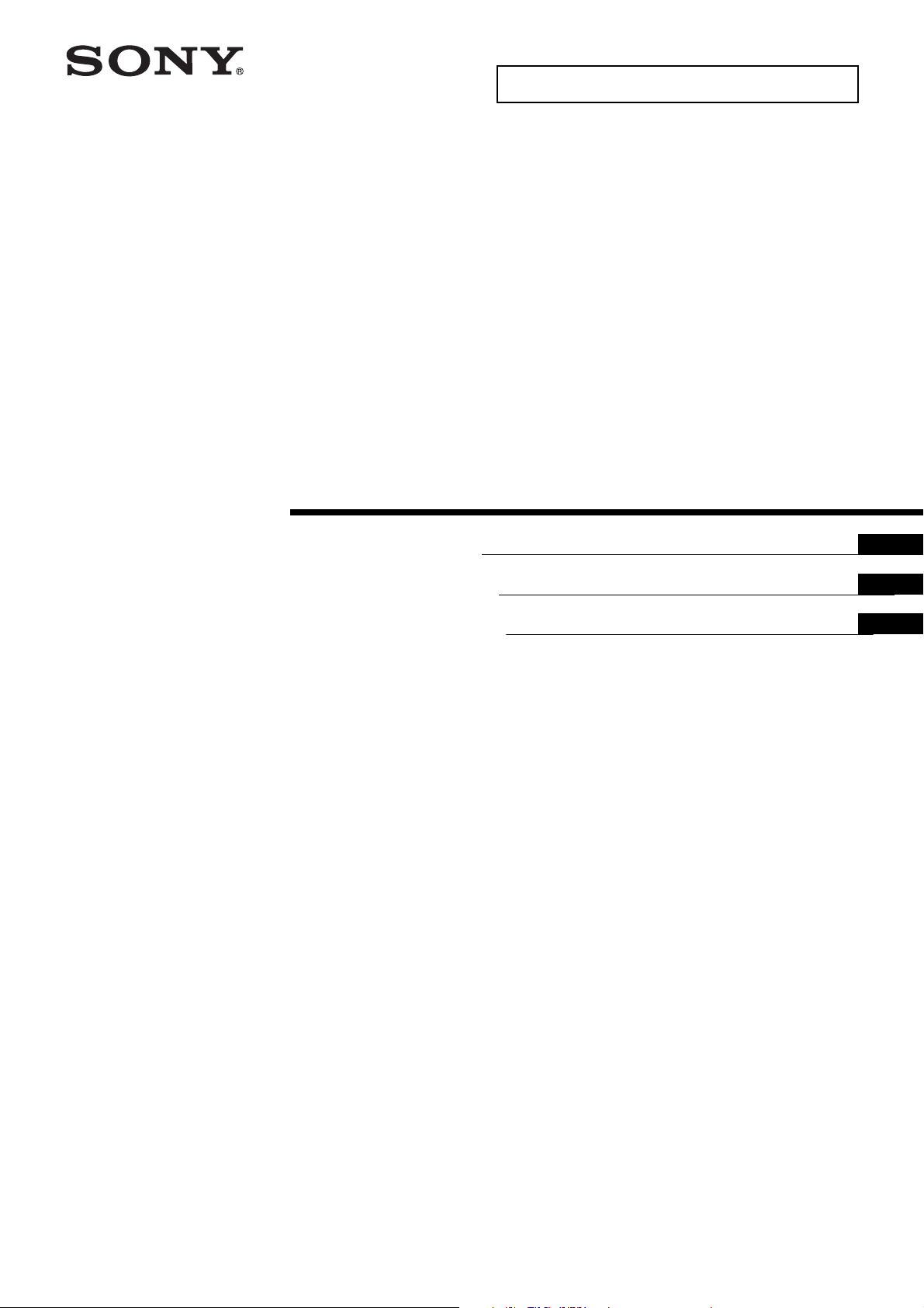
There are 4 types of installation. It may not be possible to install some types of TVs. Check the following and
install your TV in the adequate way.
AC adaptor holder kit SU-AH1 is not be able to installed.
A: Landscape, -20° leaning B: Landscape, +60° leaning C: Portrait, no leaning D: Portrait, +20° leaning
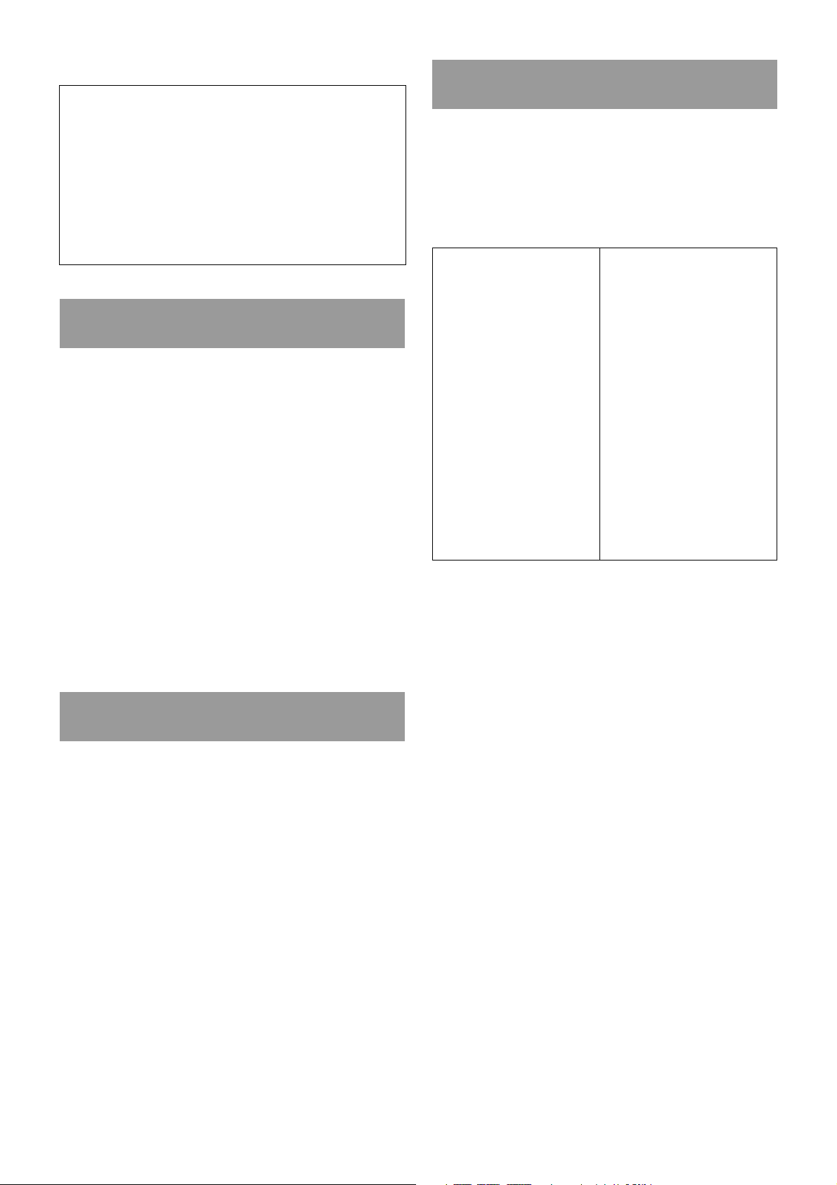
To install the TV to the wall, the SU-WL500 Wall Mount Bracket is necessary. Screws and spacers listed below are
also necessary depending on the way of installation.
For further details/terms & conditions, contact the sales representative for professional use.
TV model
XBR-75X900E KD-75X9000E
XBR-65X900E
XBR-55X900E
XBR-49X900E
XBR-75X850E KD-75X8500E
XBR-65X850E
XBR-55X800E
XBR-49X800E
XBR-43X800E KD-43X8000E
KD-65X9000E
KD-55X9000E
KD-49X9000E
KD-65X8500E
KD-55X8500E
KD-49X8000E
Installation type
A
C
A
C
A
B*3
A
B
C
D
A*5
B*5
C
D
C
D
*1
Spacer
*4
*4
*5
*5
*5
*5
*2
Wall-Mount Bracket
Model Qty
SU-WL500 1
GB
English
*1
You cannot install the TV other than the noted types.
*2
For the TV with , the following are neccesary.
Spacer: a washer with an outside diameter of 18 mm, inside diameter of 10 mm, and thickness of 2 mm
(SONY Part Number 7-688-000-32) × 20
Screw: PSW M6 × 25 mm (SONY Part Number 4-577-326-01) × 4 (1 pk)
*3
Make brightness setting to Standard or Custom 45 and lower.
*4
Make brightness setting of KD-55X8500E to Standard or Custom 30 and lower.
*5
Make brightness setting to Standard or Custom 35 and lower.
3 (GB)
Page 4
WARNING
Unit: mm (inches)
300
(11
7
/8)
100
(4)
100
(4)
100
(4)
Unit: mm (inches)
300
(11
7
/8)
100
(4)
100
(4)
100
(4)
If the following precautions are not observed,
serious injury or death through fire, electric
shock, the product toppling over, or the
product dropping can result.
Do not block the ventilation holes of
the TV.
If you block the ventilation holes with tapes or other
objects, heat builds up inside the TV and may cause a
fire.
Be sure to read thoroughly the all safety information
described in the instruction manual of SU-WL500.
Do NOT use SU-WL450 for installation in the way
noted in this manual.
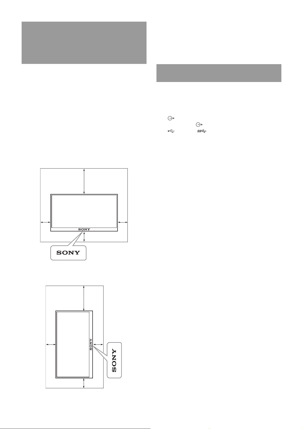
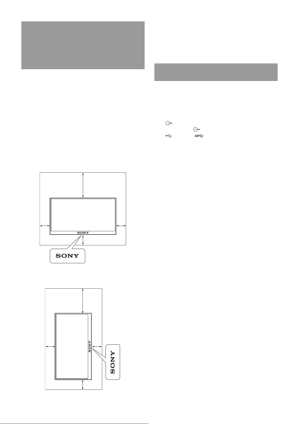
Provide adequate clearances
around the TV.
The following illustration shows how much space is
required around the TV.
Be sure to install the TV in the orientation shown in
the following illustration.
Landscape
Others
• When installing in portrait orientation, only the
following input/output jacks are available:
– HDMI IN 1/2/3/4 (Support 4K resolution, HDCP
2.2-compatible)
– DIGITAL AUDIO OUT (OPTICAL)
–AUDIO OUT / (Stereo mini jack)
– USB 1/2, USB 3
– LAN
– HDMI1 AUDIO IN (There may be no jack
depending on the country or region.)
• If you cover the illumination LED and its
surroundings with tapes or other objects, the
status of the TV cannot be recognized and the
remote control may not work.
• When carrying the TV, hold it in landscape
orientation, and take care not to drop it when
installing. Do not apply excessive force to the TV;
otherwise, it may be deformed.
Portrait
4 (GB)
Page 5
A: landscape, -20° leaning
Step 1:
Checking the parts
required for the
installation
Follow Step 1 in the SU-WL500 instruction manual to
check the parts.
Step 2:
Deciding on the
installation location
Follow Step 2 in the SU-WL500 instruction manual to
decide on the installation location. Refer to page 18
of this manual for the TV installation dimension table.
Step 4:
Preparing for the
installation of the TV
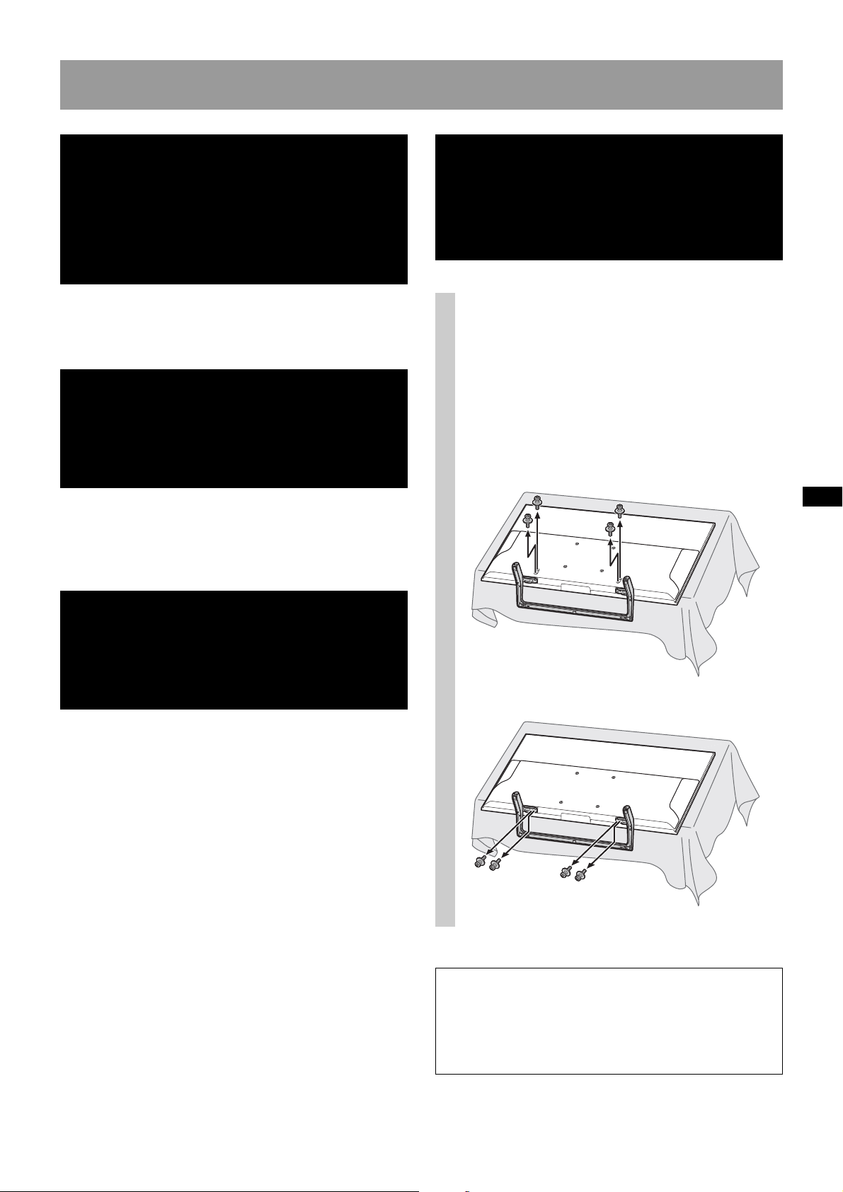
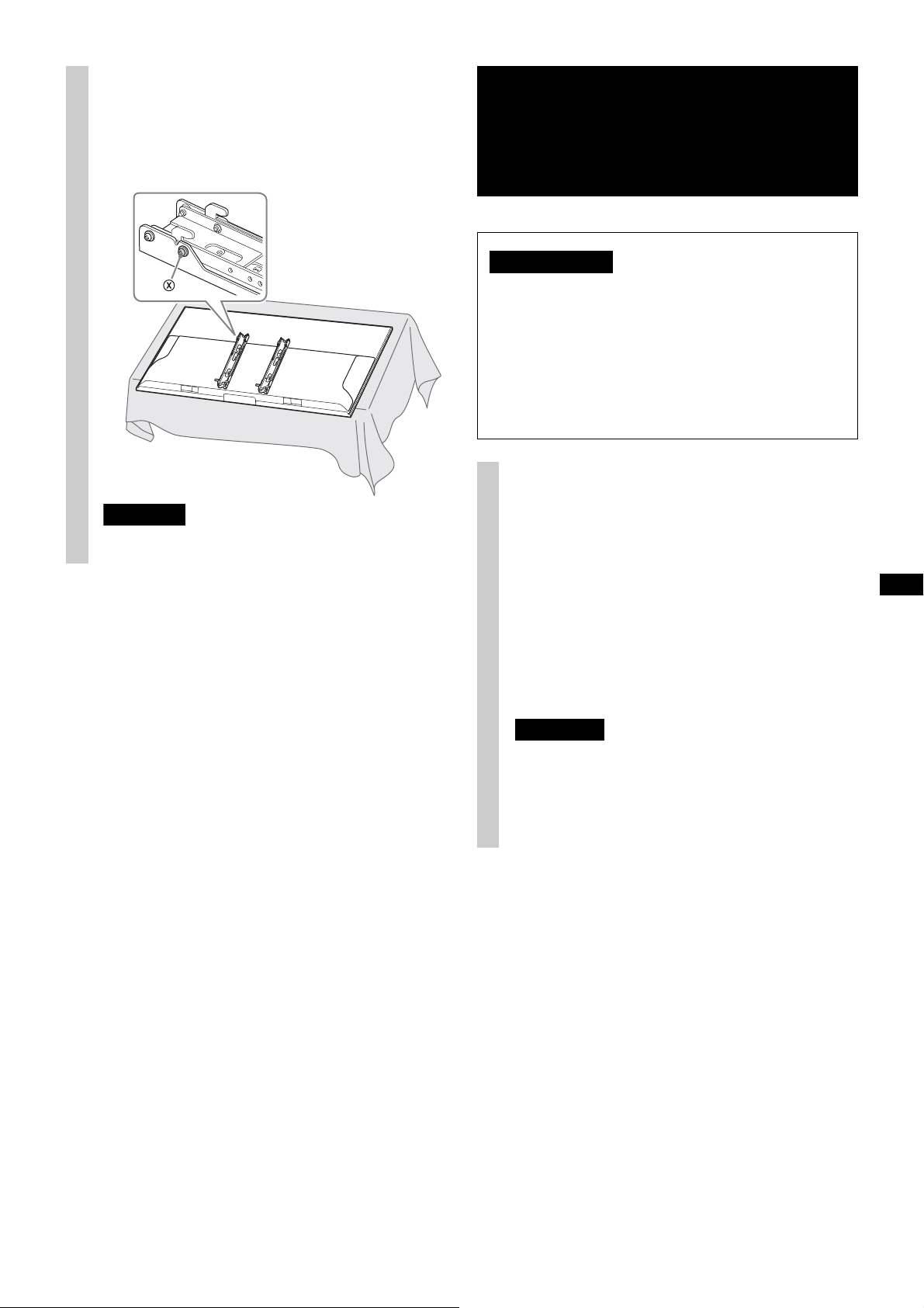
Remove the stand if it is
1
installed to the TV.
Lay down the TV and lay a soft cloth under the
TV to protect the TV monitor.
XBR-75X900E/XBR-65X900E/XBR-55X900E/
XBR-49X900E/XBR-75X850E/XBR-65X850E/
XBR-55X800E/KD-75X9000E/KD-65X9000E/
KD-55X9000E/KD-49X9000E/KD-75X8500E/
KD-65X8500E/KD-55X8500E
Step 3:
Installing the Base
Bracket on the wall
Follow Step 3 in the SU-WL500 instruction manual to
install the Base Bracket.
XBR-49X800E/KD-49X8000E
When using an electric screwdriver, set the torque
setting to approximately 2 N·m {20 kgf·cm}.
Do not lift the Mounting Hook before the screws
(two screws each for left/right) are secured. This
may distort the Mounting Hook or the TV cabinet.
5 (GB)
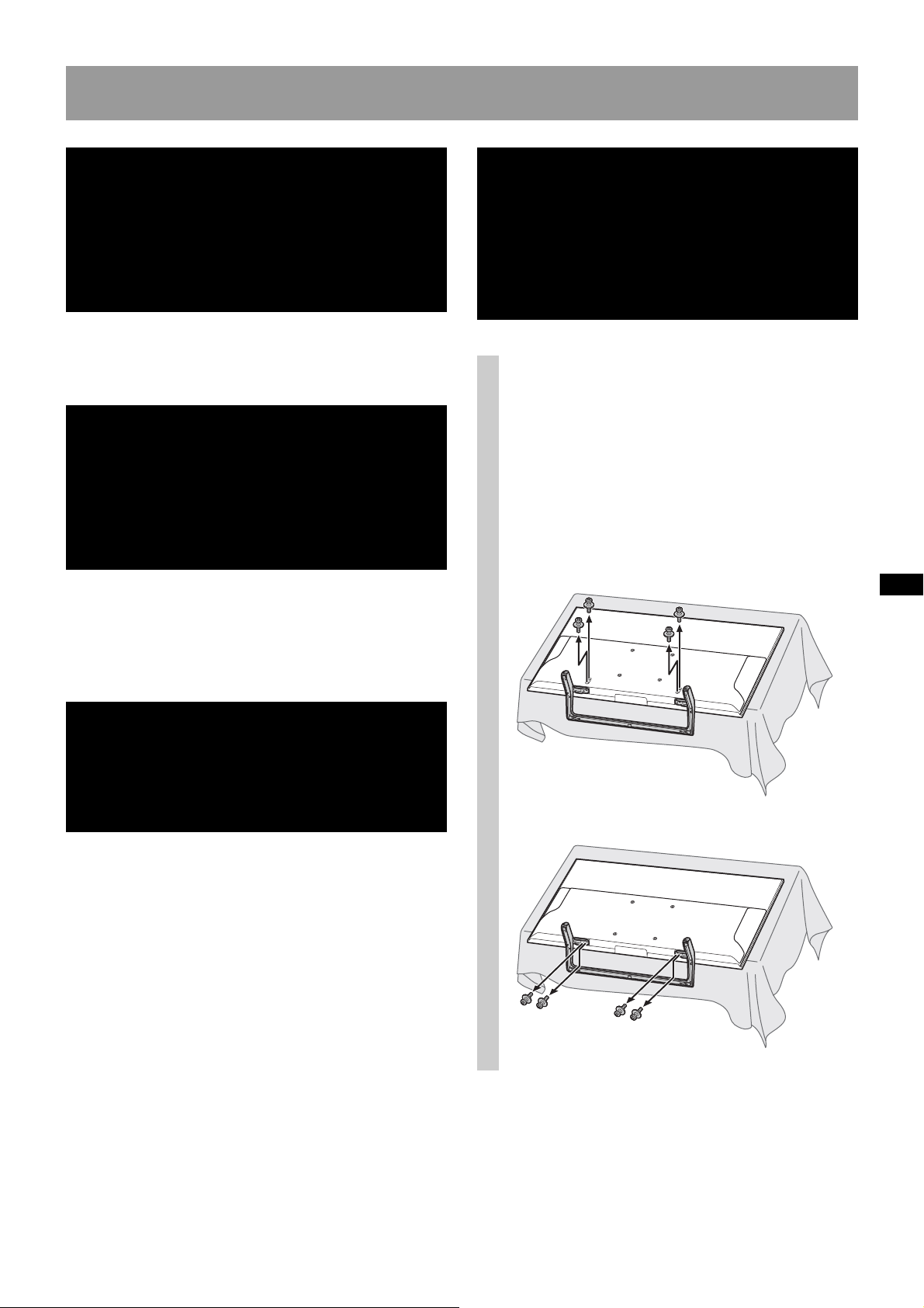
Page 6
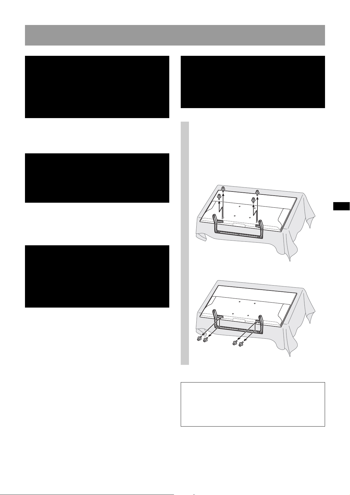
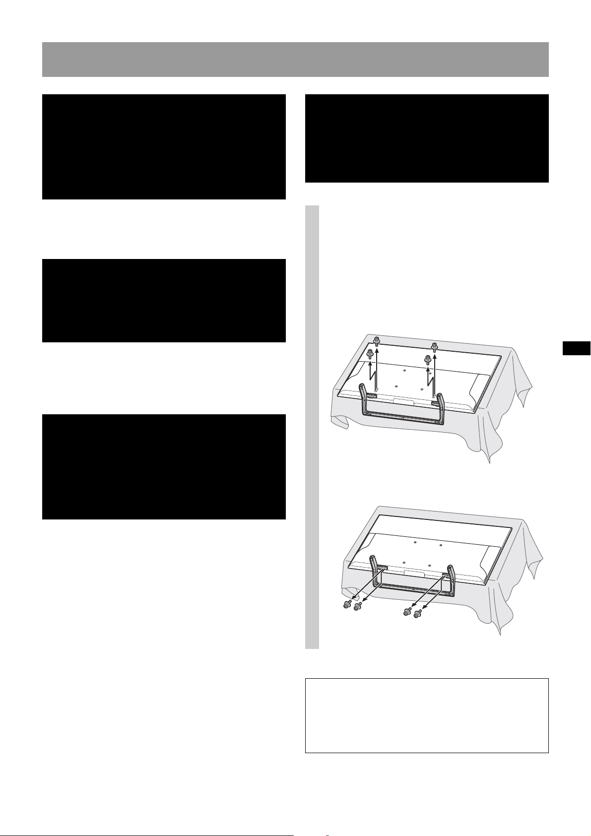
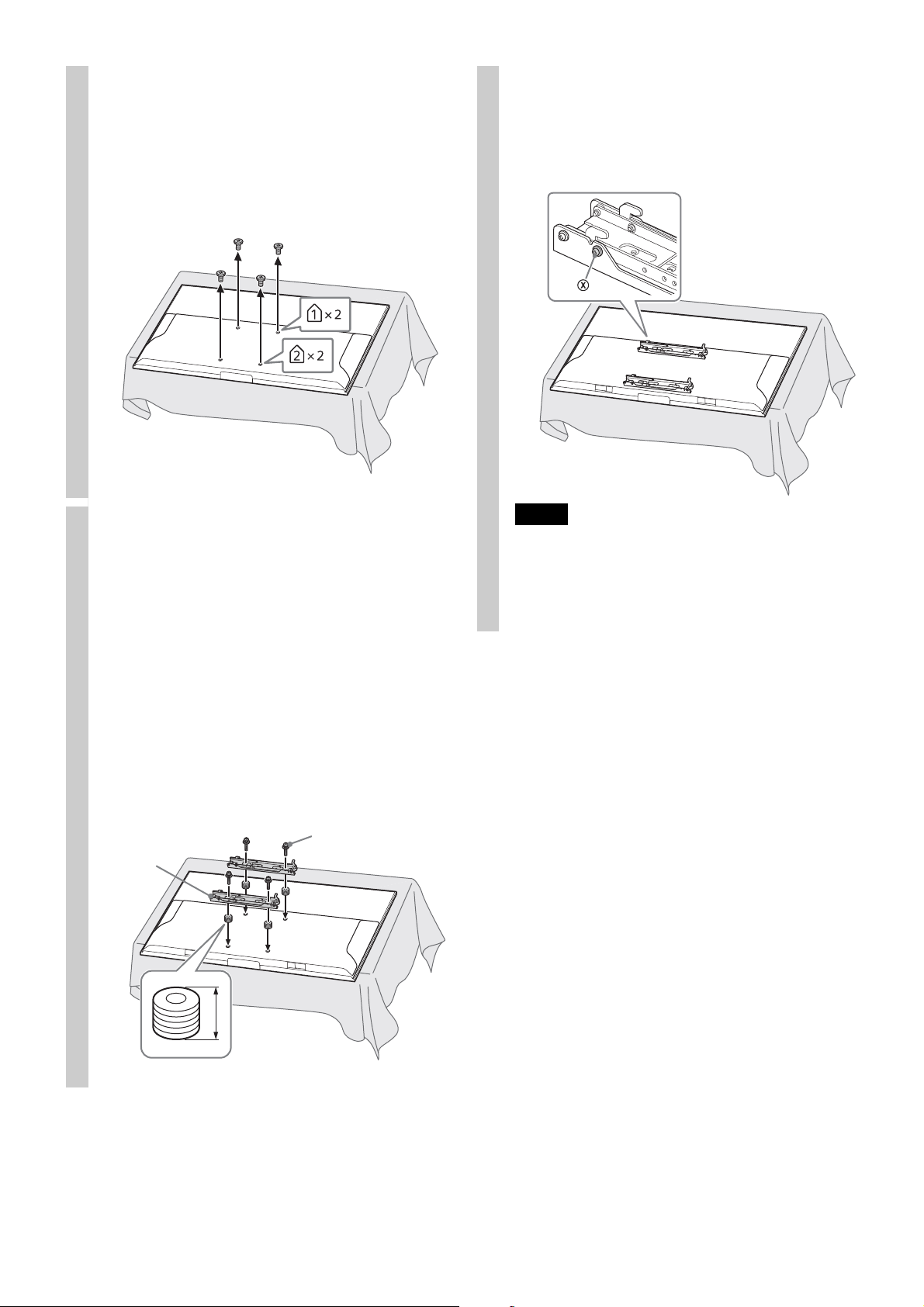
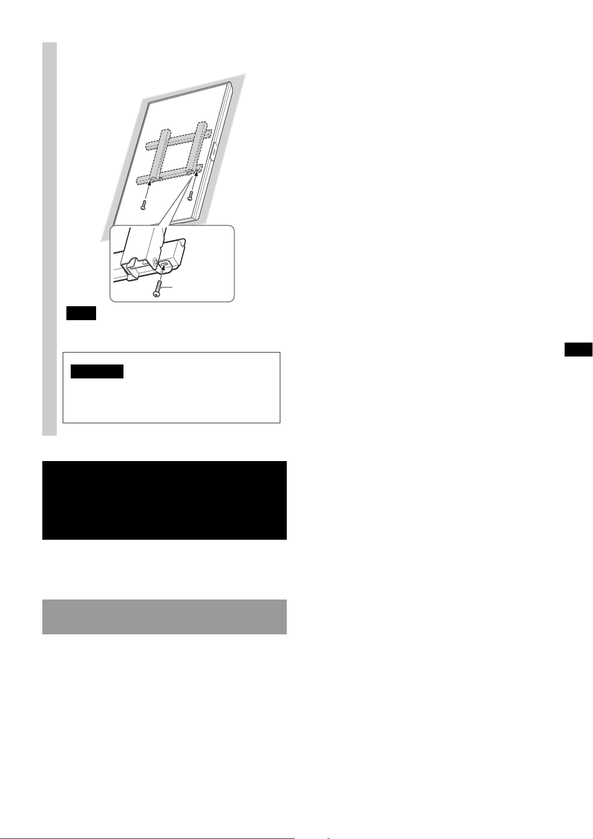
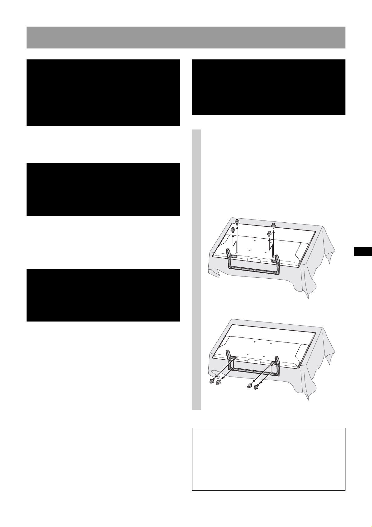
Remove the screws from the
Mounting Hook
Screw
*1, *2
Spacer
*1, *2
10 mm (13/32 inch)
2
rear of the TV.
XBR-75X900E/XBR-65X900E/XBR-55X900E/
XBR-49X900E/XBR-65X850E/KD-75X9000E/
KD-65X9000E/KD-55X9000E/KD-49X9000E/
KD-65X8500E/KD-55X8500E
XBR-75X850E/KD-75X8500E
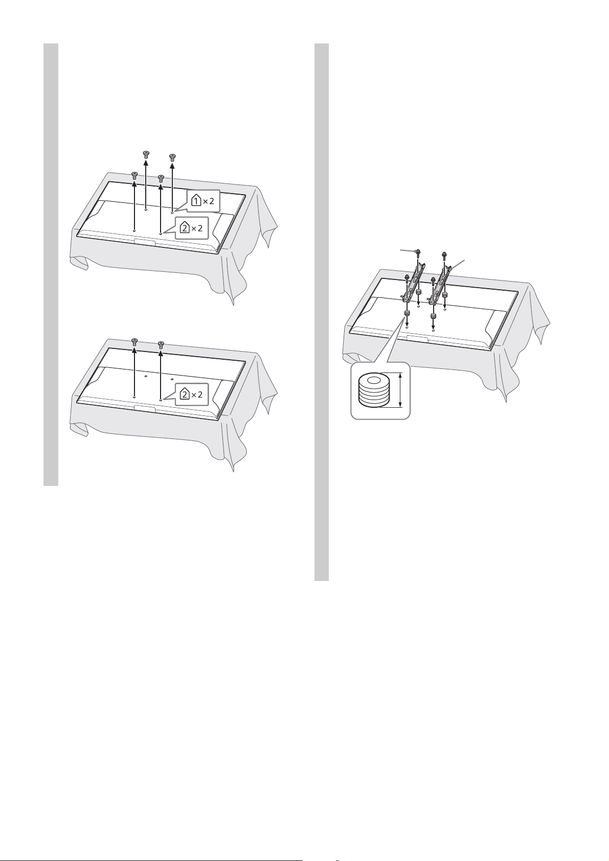
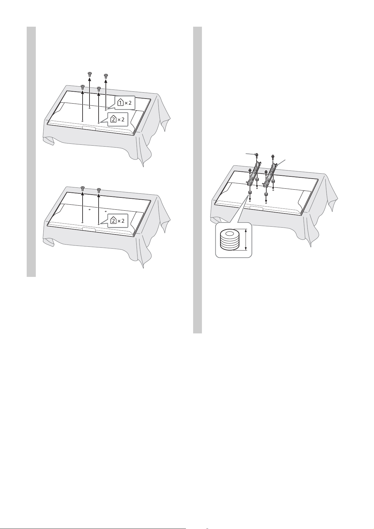
Referring to the Screw and Hook
3
locations diagram/table on
page 20, determine the screw
positions, and secure the
Mounting Hook to the rear of the
TV.
Secure the Mounting Hook to the rear of the
TV temporarily, using the four screws
Be sure that both screws are securely
tightened with equal torque strength to the
rear of the TV.
(*1, *2)
.
*1
Needs 5 spacers (not supplied) and screws
PSW M6 × 25 mm (not supplied):
XBR-75X900E/XBR-75X850E/XBR-65X850E/
KD-75X9000E/KD-75X8500E/KD-65X8500E/
KD-55X8500E
*2
No spacers necessary, but screws of PSW 6 ×
16 mm are necessary (supplied):
XBR-65X900E/XBR-55X900E/XBR-49X900E/
XBR-55X800E/XBR-49X800E/KD-65X9000E/
KD-55X9000E/KD-49X9000E/KD-49X8000E
6 (GB)
Page 7
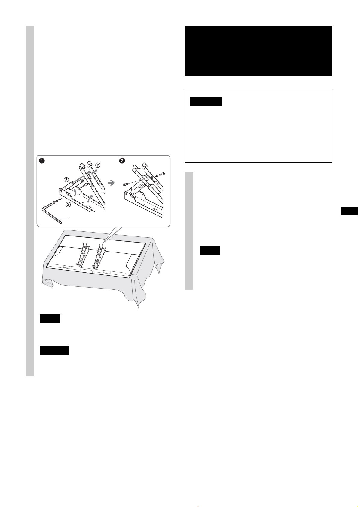
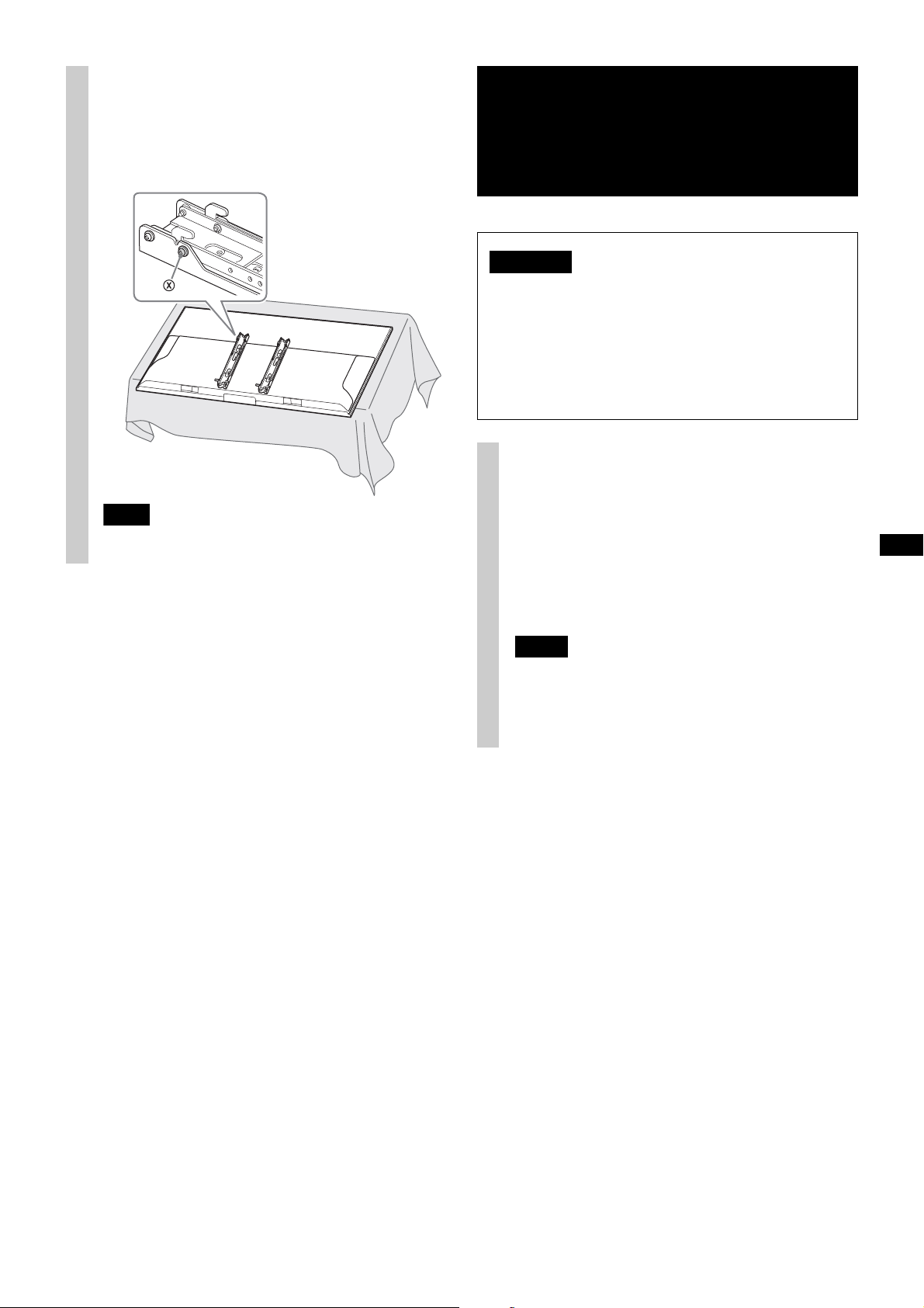
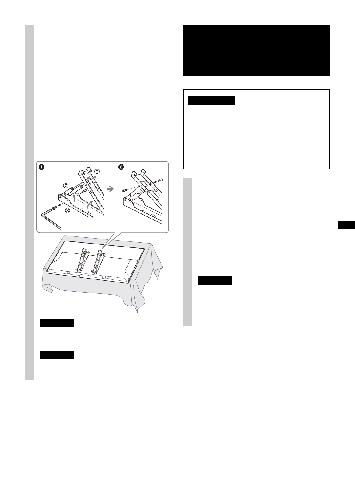
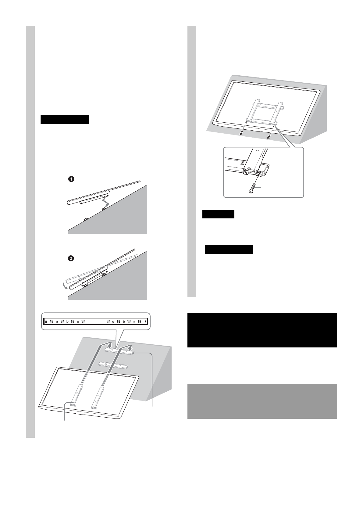
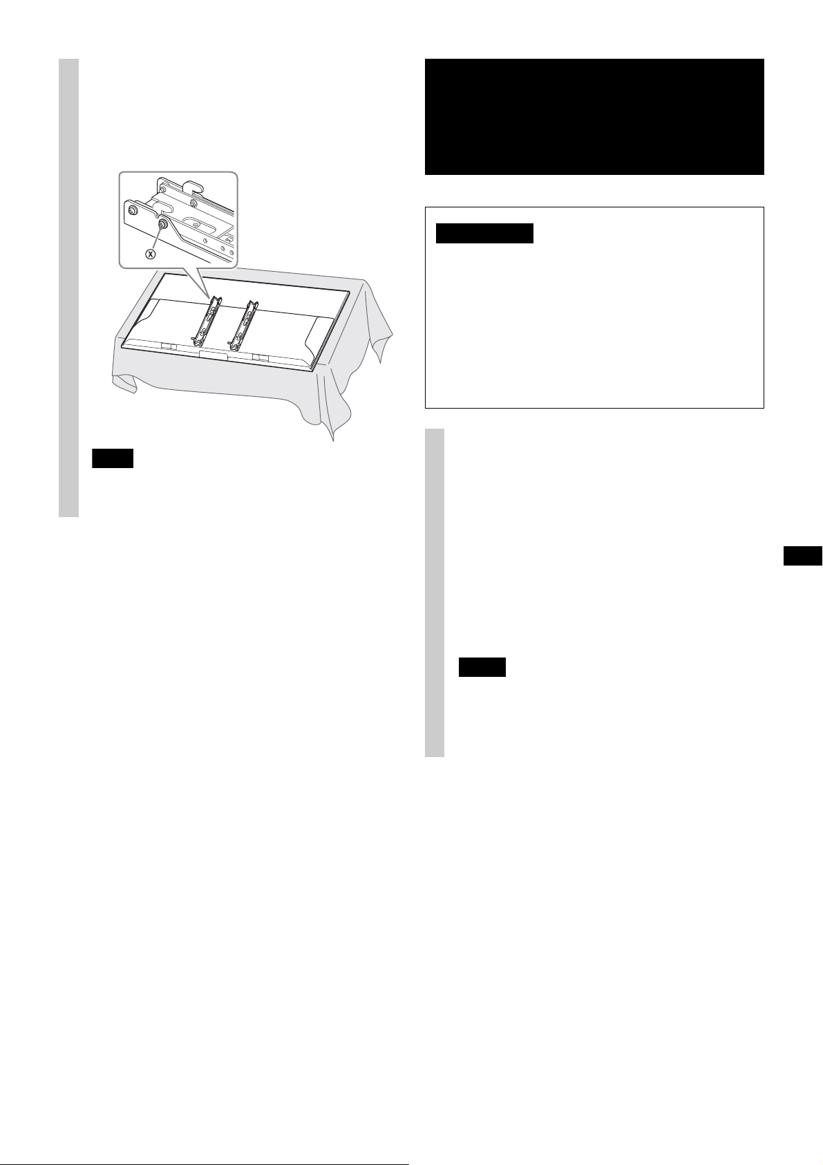
Adjust the angle of the
Notes
CAUTION
Hex key
WARNING
Notes
4
Mounting Hook with the
supplied hex key.
Perform following and . Make sure that
screw firmly secures the arm base of the
Mounting Hook (both left and right).
Remove the 2 screws from the arm base
of the Mounting Hook (both left and right)
and determine the screw holes for the angle
(20°) you plan to change to.
Fit screw holes of the upper arm and
lower arm in an adequate angle, put
screws removed in step into the holes,
then secure both arms.
Step 5:
Installing the TV on the
wall
Be sure to complete the installation before
connecting the AC power cord to the wall outlet. If
you allow the AC power cord to be pinched under
or between pieces of equipment, this may result
in a short circuit or an electric shock.
Be careful not to stumble over the AC power cord
or the TV, as you may hurt yourself.
Connect the AC power cord and
1
the connecting cable(s) supplied
with the TV to the TV.
Connect the AC power cord and the connecting
cable(s) to the connectors on the rear of the TV.
For details on connecting the AC power cord
and the connecting cable(s), refer to the
instruction manual of the TV.
• Make sure that the adjusted angle of both arms are
the same.
• Make sure that both arms are screwed in securely.
• Be careful not to get your fingers caught while
adjusting the angle.
• You cannot connect the cables to the TV after
installing it on the Base Bracket.
• Subcontract the cable routing in the wall to a
licensed contractor.
7 (GB)
Page 8
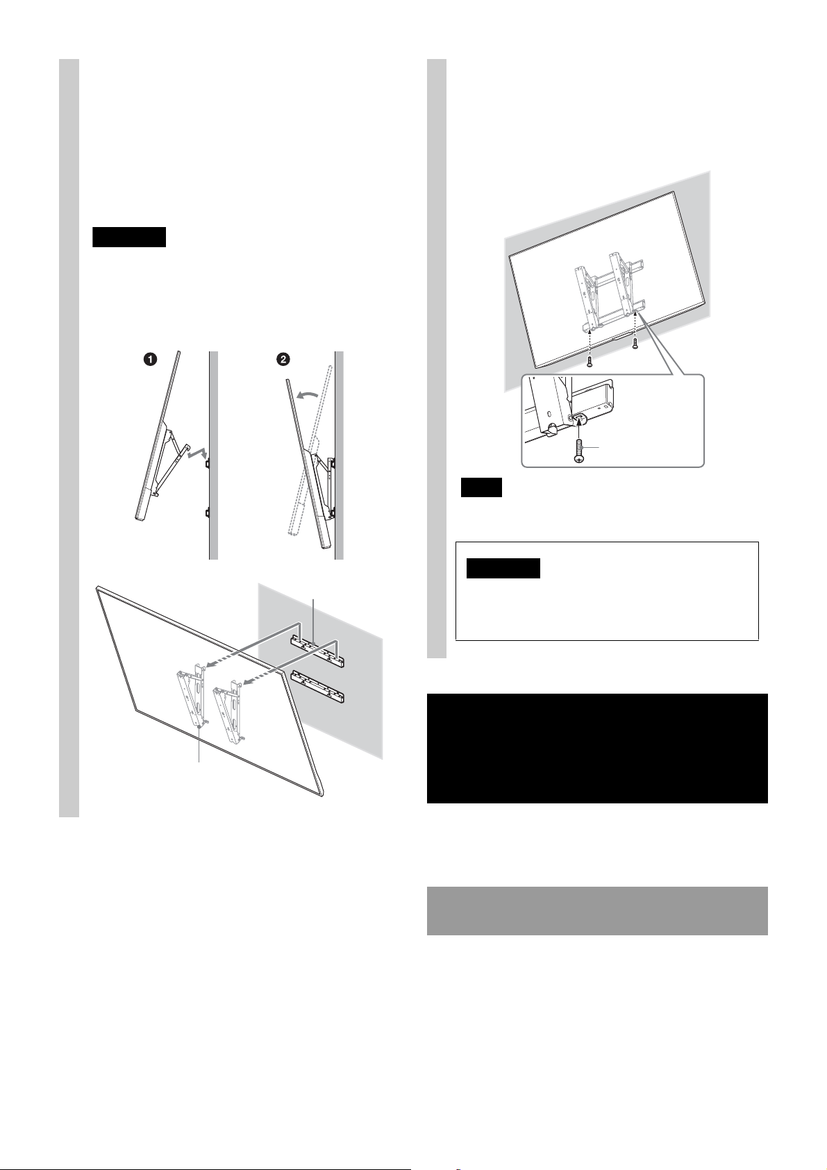
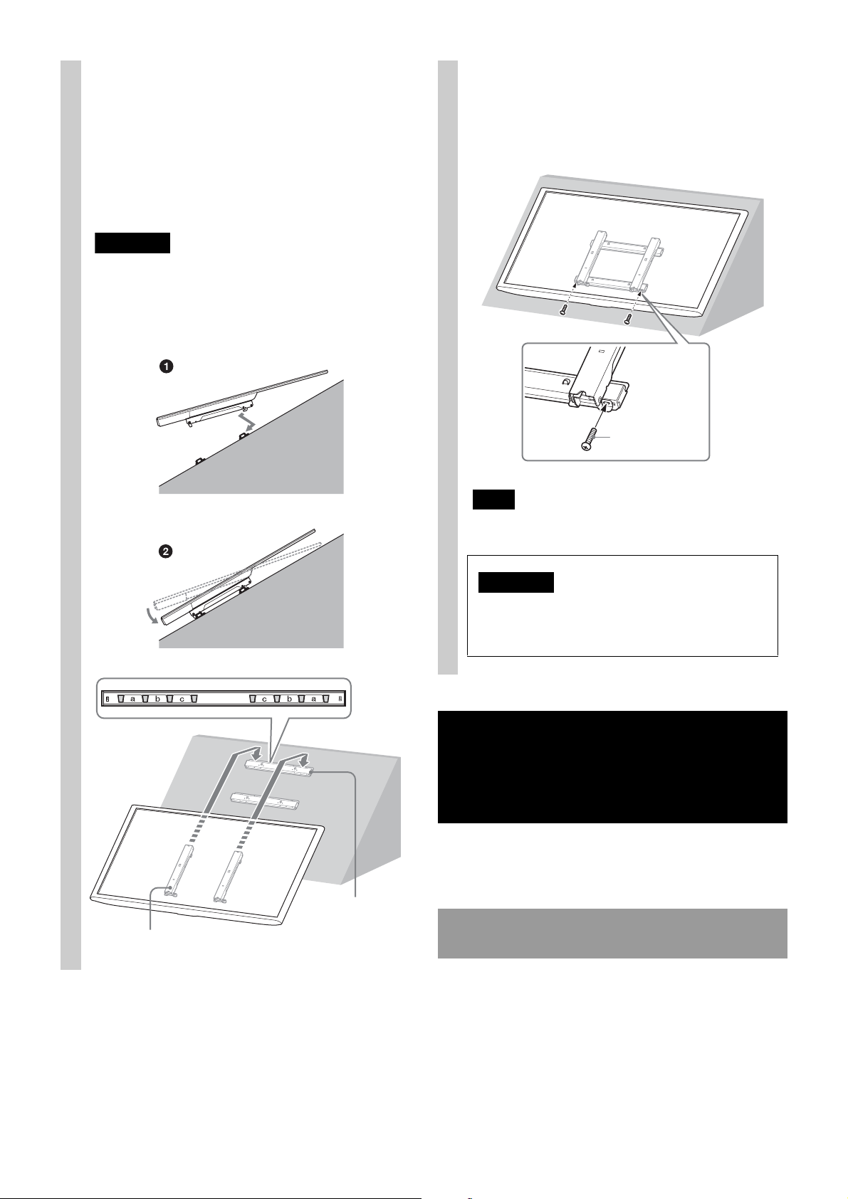
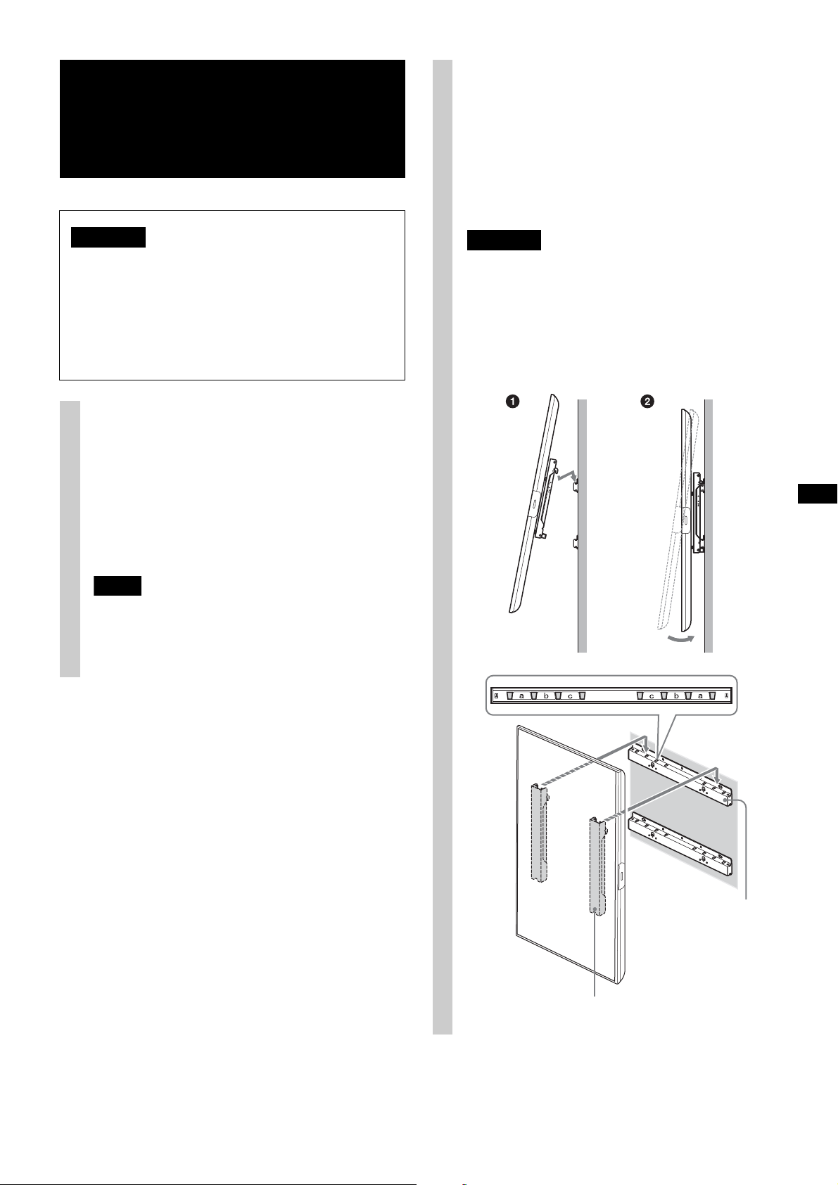
Install the TV onto the Base
WARNING
Base Bracket
Mounting Hook
Note
Screw
(+BVST4 × 12)
WARNING
Be sure to tighten the securing screw firmly.
If you fail to do so, the TV may fall when it is
pushed upward and cause injury.
2
Bracket.
Referring to the Screw and Hook locations
diagram/table on page 20, determine the
holes of the Base Bracket for latching the
upper hooks of the Mounting Hook.
Hold the TV securely with both hands, and
gently align it on the wall.
• Be sure that two or more persons hold the TV when
carrying it.
• When carrying the TV, hold it in landscape
orientation, and take care not to drop it when
installing. Do not apply excessive force to the TV;
otherwise, it may be deformed.
Firmly secure the TV and the
3
Base Bracket using the screw
supplied with SU-WL500
(+BVST4 × 12).
When using an electric screwdriver, set the torque
setting to approximately 1.5 N·m {15 kgf·cm}.
Confirming the
completion of the
installation
Follow the instructions in the SU-WL500 instruction
manual to confirm.
8 (GB)
When removing the TV
Follow the instructions in the SU-WL500 instruction
manual to remove.
Page 9
B: landscape, +60° leaning
Step 1:
Checking the parts
required for the
installation
Follow Step 1 in the SU-WL500 instruction manual to
check the parts.
Step 2:
Deciding on the
installation location
Follow Step 2 in the SU-WL500 instruction manual to
decide on the installation location. Refer to page 18
of this manual for the TV installation dimension table.
Step 4:
Preparing for the
installation of the TV
Remove the stand if it is
1
installed to the TV.
Lay down the TV and lay a soft cloth under the
TV to protect the TV monitor.
XBR-75X850E/XBR-65X850E/XBR-55X800E/
KD-75X8500E/KD-65X8500E/KD-55X8500E
Step 3:
Installing the Base
Bracket on the wall or
mounting
Follow Step 3 in the SU-WL500 instruction manual to
install the Base Bracket.
XBR-49X800E/KD-49X8000E
When using an electric screwdriver, set the torque
setting to approximately 2 N·m {20 kgf·cm}.
Do not lift the Mounting Hook before the screws
(two screws each for left/right) are secured. This
may distort the Mounting Hook or the TV cabinet.
9 (GB)
Page 10
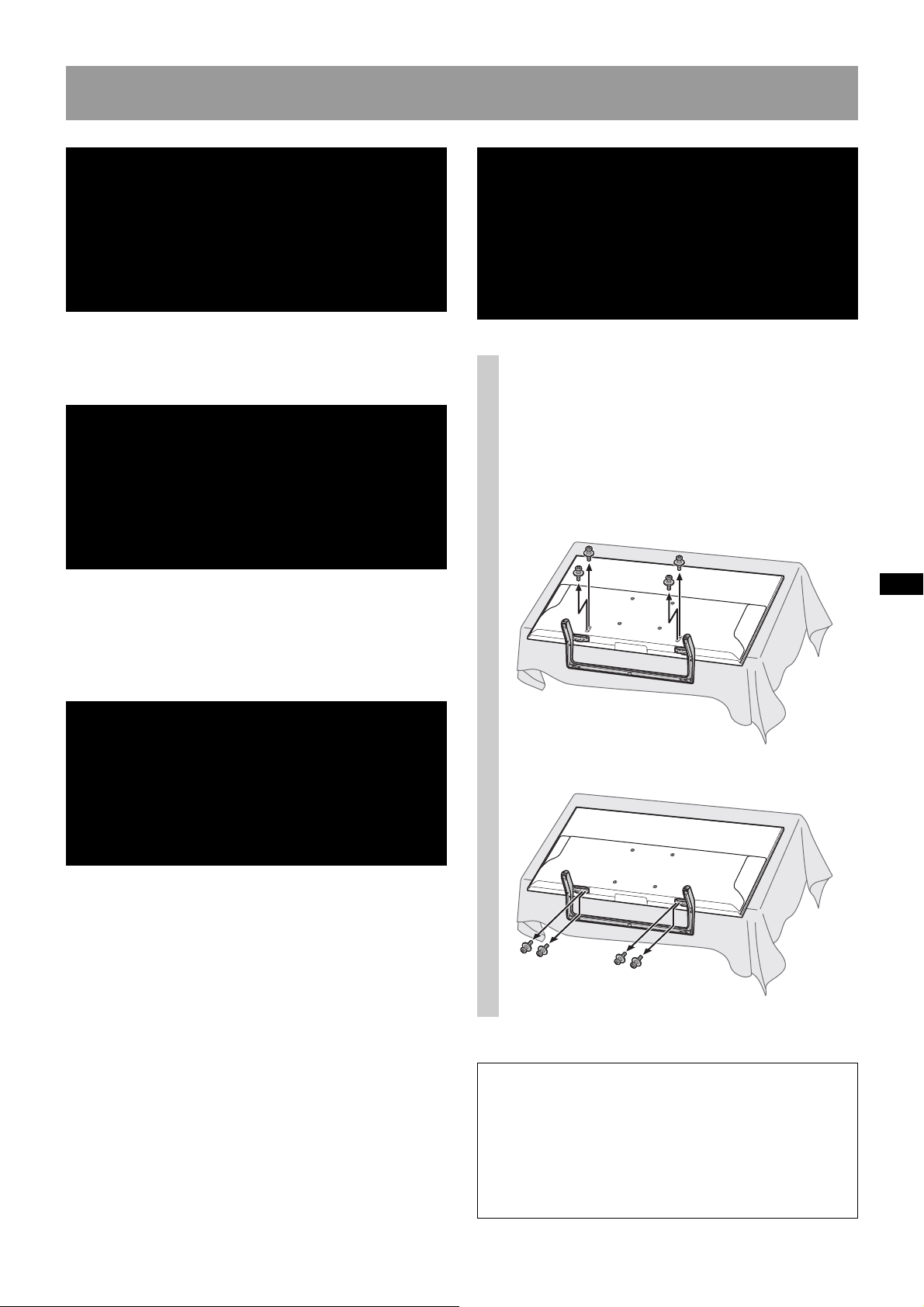
Remove the screws from the
Mounting Hook
Screw
*1, *2
Spacer
*1, *2
10 mm (13/32 inch)
2
rear of the TV.
XBR-65X850E/KD-65X8500E/KD-55X8500E
XBR-75X850E/KD-75X8500E
Referring to the Screw and Hook
3
locations diagram/table on
page 20, determine the screw
positions, and secure the
Mounting Hook to the rear of the
TV.
Secure the Mounting Hook to the rear of the
TV temporarily, using the four screws
Be sure that both screws are securely
tightened with equal torque strength to the
rear of the TV.
(*1, *2)
.
*1
Needs 5 spacers (not supplied) and screws
PSW M6 × 25 mm (not supplied):
XBR-65X850E/KD-65X8500E/KD-55X8500E
*2
No spacers necessary, but screws of PSW 6 ×
16 mm are necessary (supplied):
XBR-75X850E/XBR-55X800E/XBR-49X800E/
KD-75X8500E/KD-49X8000E
10 (GB)
Page 11
Make sure that the screw
Note
WARNING
Notes
4
firmly secures the arm base of
the Mounting Hook (both left
and right).
Make sure that the two arms are screwed in securely.
Step 5:
Installing the TV on the
wall
Be sure to complete the installation before
connecting the AC power cord to the wall outlet. If
you allow the AC power cord to be pinched under
or between pieces of equipment, this may result
in a short circuit or an electric shock.
Be careful not to stumble over the AC power cord
or the TV, as you may hurt yourself.
Connect the AC power cord and
1
the connecting cable(s) supplied
with the TV to the TV.
Connect the AC power cord and the connecting
cable(s) to the connectors on the rear of the TV.
For details on connecting the AC power cord
and the connecting cable(s), refer to the
instruction manual of the TV.
• You cannot connect the cables to the TV after
installing it on the Base Bracket.
• Subcontract the cable routing in the wall to a
licensed contractor.
11 (GB)
Page 12
Install the TV onto the Base
WARNING
Base Bracket
Mounting Hook
Note
Screw
(+BVST4 × 12)
WARNING
Be sure to tighten the securing screw firmly.
If you fail to do so, the TV may fall when it is
pushed upward and cause injury.
2
Bracket.
Referring to the Screw and Hook locations
diagram/table on page 20, determine the
holes of the Base Bracket for latching the
upper hooks of the Mounting Hook.
Hold the TV securely with both hands, and
gently align it on the wall.
• Be sure that two or more persons hold the TV when
carrying it.
• When carrying the TV, hold it in landscape
orientation, and take care not to drop it when
installing. Do not apply excessive force to the TV;
otherwise, it may be deformed.
Firmly secure the TV and the
3
Base Bracket using the screw
supplied with SU-WL500
(+BVST4 × 12).
When using an electric screwdriver, set the torque
setting to approximately 1.5 N·m {15 kgf·cm}.
Confirming the
completion of the
installation
Follow the instructions in the SU-WL500 instruction
manual to confirm.
12 (GB)
When removing the TV
Follow the instructions in the SU-WL500 instruction
manual to remove.
Page 13
C: portrait, no leaning / D: portrait, +20° leaning
Step 1:
Checking the parts
required for the
installation
Follow Step 1 in the SU-WL500 instruction manual to
check the parts.
Step 2:
Deciding on the
installation location
Follow Step 2 in the SU-WL500 instruction manual to
decide on the installation location. Refer to page 19
of this manual for the TV installation dimension table.
Step 4:
Preparing for the
installation of the TV
Remove the stand if it is
1
installed to the TV.
Lay down the TV and lay a soft cloth under the
TV to protect the TV monitor.
XBR-75X900E/XBR-65X900E/XBR-55X900E/
XBR-49X900E/XBR-65X850E/XBR-55X800E/
KD-75X9000E/KD-65X9000E/KD-55X9000E/
KD-49X9000E/KD-65X8500E/KD-55X8500E
Step 3:
Installing the Base
Bracket on the wall or
mounting
Follow Step 3 in the SU-WL500 instruction manual to
install the Base Bracket.
XBR-49X800E/XBR-43X800E/KD-49X8000E/
KD-43X8000E
When using an electric screwdriver, set the torque
setting to approximately 2 N·m {20 kgf·cm}.
Do not lift the Mounting Hook before the screws
(two screws each for left/right) are secured. This
may distort the Mounting Hook or the TV cabinet.
13 (GB)
Page 14
Remove the screws from the
Screw
(+PSW6 × 25)
(not supplied)
Mounting
Hook
Spacer × 5
(not supplied)
10 mm (13/32 inch)
Notes
2
rear of the TV.
XBR-75X900E/XBR-65X900E/XBR-55X900E/
XBR-49X900E/XBR-65X850E/KD-75X9000E/
KD-65X9000E/KD-55X9000E/KD-49X9000E/
KD-65X8500E/KD-55X8500E
Referring to the Screw and Hook
3
locations diagram/table on
page 20, determine the screw
positions, and secure the
Mounting Hook to the rear of the
TV.
Make sure that the screw
4
firmly secures the arm base of
the Mounting Hook (both left
and right).
• When installing in portrait orientation, be sure to
keep the Mounting Hook angle to 0 degrees. Do
not use another angles.
• Make sure that the two arm bases are screwed in
securely.
Secure the Mounting Hook to the rear of the
TV temporarily, using the four screws
(+PSW6 × 25).
Be sure that both screws are securely
tightened with equal torque strength to the
rear of the TV.
14 (GB)
Page 15
Step 5:
WARNING
Notes
WARNING
Base Bracket
Mounting Hook
Installing the TV on the
wall
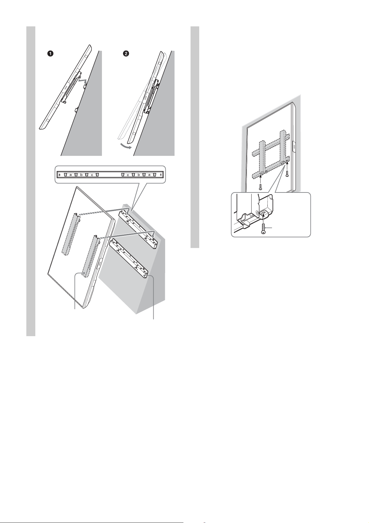
Install the TV onto the Base
2
Bracket.
Referring to the Screw and Hook locations
diagram/table on page 20, determine the
holes of the Base Bracket for latching the
upper hooks of the Mounting Hook.
Hold the TV securely with both hands, and
gently align it on the wall.
Be sure to complete the installation before
connecting the AC power cord to the wall outlet. If
you allow the AC power cord to be pinched under
or between pieces of equipment, this may result
in a short circuit or an electric shock.
Be careful not to stumble over the AC power cord
or the TV, as you may hurt yourself.
Connect the AC power cord and
1
the connecting cable(s) supplied
with the TV to the TV.
Connect the AC power cord and the connecting
cable(s) to the connectors on the rear of the TV.
For details on connecting the AC power cord
and the connecting cable(s), refer to the
instruction manual of the TV.
• You cannot connect the cables to the TV after
installing it on the Base Bracket.
• Subcontract the cable routing in the wall to a
licensed contractor.
• Be sure that two or more persons hold the TV when
carrying it.
• When carrying the TV, hold it in landscape
orientation, and take care not to drop it when
installing. Do not apply excessive force to the TV;
otherwise, it may be deformed.
C: Portrait, no leaning
15 (GB)
Page 16
D: Portrait, +20° leaning
Base Bracket
Mounting Hook
Screw
(+BVST4 × 12)
Firmly secure the TV and the
3
Base Bracket using the screw
supplied with SU-WL500
(+BVST4 × 12).
C: Portrait, no leaning
16 (GB)
Page 17
D: Portrait, +20° leaning
Note
Screw
(+BVST4 × 12)
WARNING
Be sure to tighten the securing screw firmly.
If you fail to do so, the TV may fall when it is
pushed upward and cause injury.
When using an electric screwdriver, set the torque
setting to approximately 1.5 N·m {15 kgf·cm}.
Confirming the
completion of the
installation
Follow the instructions in the SU-WL500 instruction
manual to confirm.
When removing the TV
Follow the instructions in the SU-WL500 instruction
manual to remove.
17 (GB)
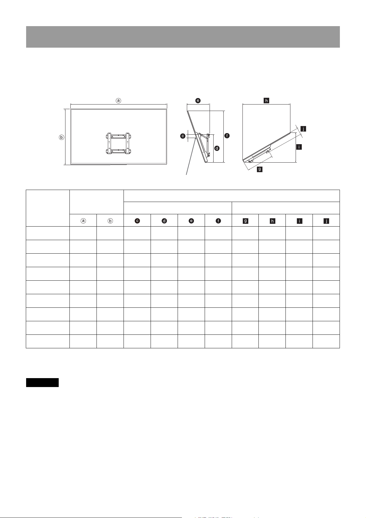
Page 18
WARNING
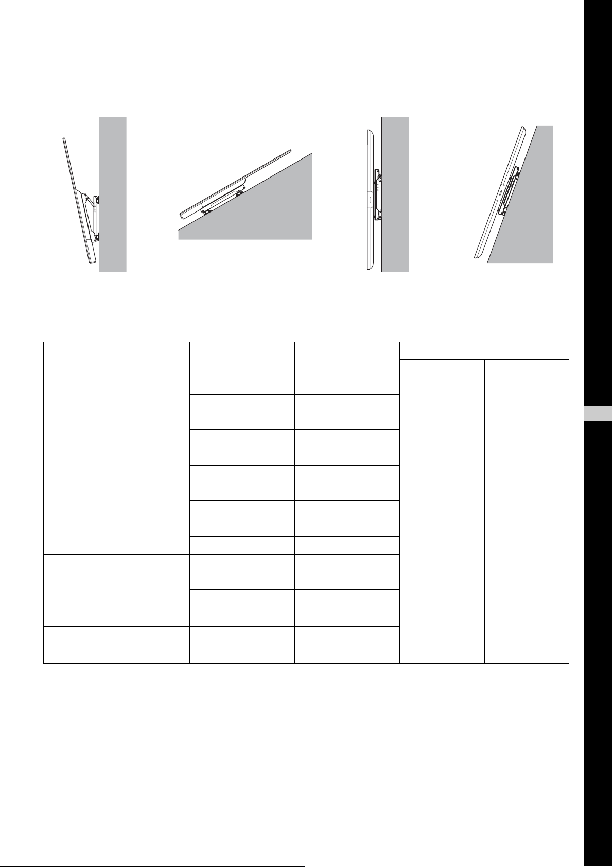
TV installation dimensions table
Screen center point
The table below shows the dimensions of the TV that is mounted on this product. Refer to this table to decide
on the installation location.
A: Landscape, -20° leaning
B: Landscape, +60° leaning
Unit: mm (inches)
Length for each mounting angle
410
(16 1/4)
369
(14 5/8)
327
(12 7/8)
297
(11 3/4)
424
(16 3/4)
353
(14)
322
(12 3/4)
330
(13)
315
(12 1/2)
(35 1/2)
(30 3/4)
(26 1/4)
(23 3/8)
(35 7/8)
(31 1/8)
(26 5/8)
(26 5/8)
(23 3/4)
Model Name
XBR-75X900E
KD-75X9000E
XBR-65X900E
KD-65X9000E
XBR-55X900E
KD-55X9000E
XBR-49X900E
KD-49X9000E
XBR-75X850E
KD-75X8500E
XBR-65X850E
KD-65X8500E
KD-55X8500E
XBR-55X800E
XBR-49X800E
KD-49X8000E
Display dimensions
1,674
(66)
1,447
(57)
1,228
(48 3/8)
1,093
(43 1/8)
1,677
(66 1/8)
1,454
(57 1/4)
1,232
(48 5/8)
1,232
(48 5/8)
1,096
(43 1/4)
959
(37 7/8)98(3 7/8)
830
(32 3/4)
707
(27 7/8)
631
(24 7/8)
968
(38 1/8)11(7/16)
840
(33 1/8)
717
(28 1/4)
716
(28 1/4)
640
(25 1/4)
103
(4 1/8)
161
(6 3/8)
213
(8 1/2)
121
(4 7/8)
187
(7 3/8)
147
(5 7/8)
151
(6)
Angle (20º) Angle (60º)
549
(21 5/8)
494
(19 1/2)
494
(19 1/2)
511
(20 1/8)
469
(18 1/2)
518
(20 1/2)
527
(20 3/4)
488
(19 1/4)
456
(18)
Some models may not be available in certain regions.
Figures in the above table may differ slightly depending on the installation.
901
780
664
592
910
790
674
675
603
————
————
————
————
547
(21 5/8)
411
(16 1/4)
507
(20)
467
(18 1/2)
434
(17 1/8)
840
(33 1/8)
9
72
3/4)
(28
623
(24 5/8)
623
(24 5/8)
557
(22)
527
(20 3/4)
456
(18)
403
(15 7/8)
406
(16)
369
(14 5/8)
109
(4 3/8)
110
(4 3/8)
123
(4 7/8)
117
(4 5/8)
117
(4 5/8)
The wall that the TV will be installed on should be capable of supporting a weight of at least four times that of
the TV.
Refer to your TV’s instructions for its weight.
18 (GB)
Page 19
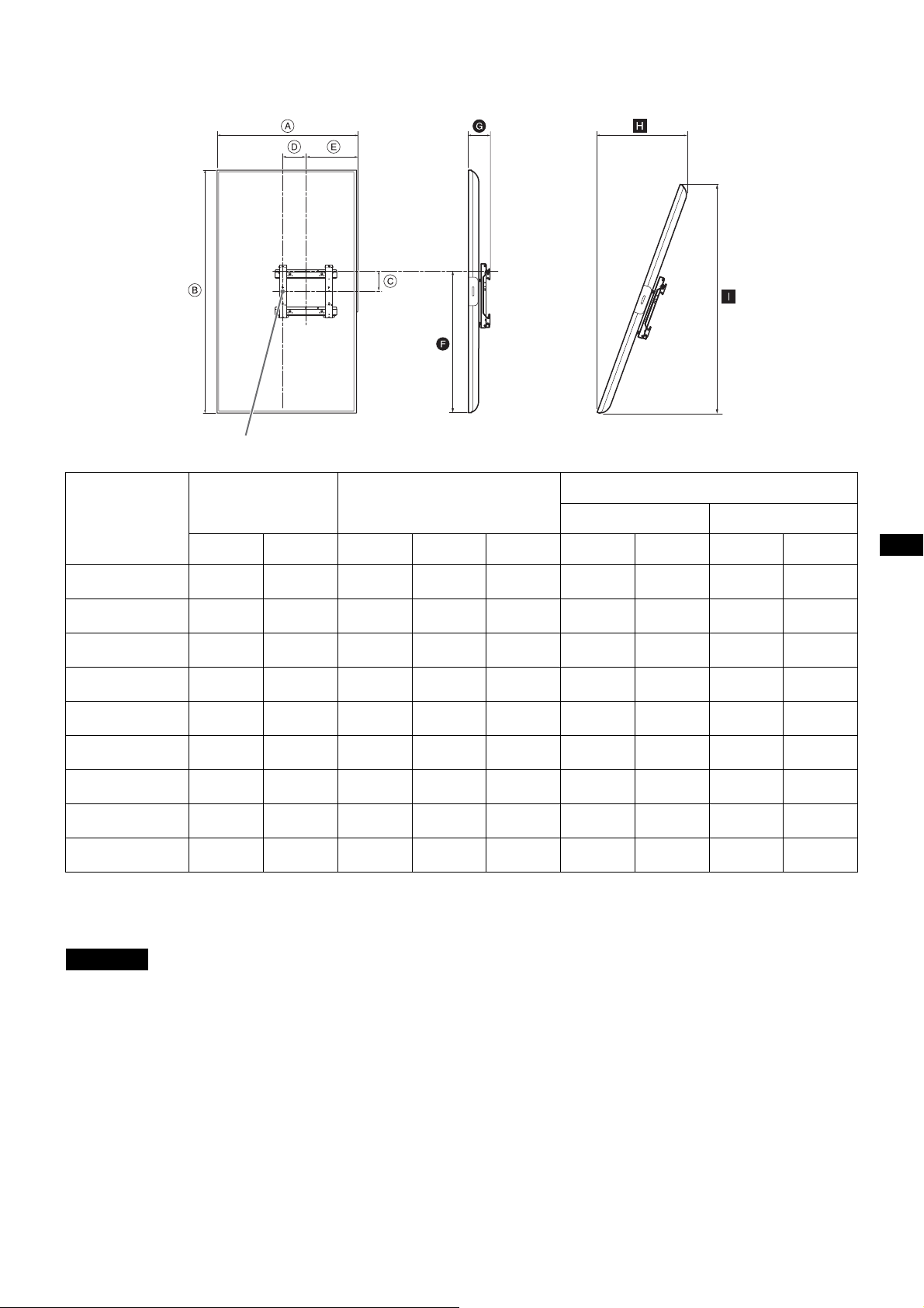
C: Portrait, no leaning
WARNING
Screen center point
D: Portrait, +20° leaning
Unit: mm (inches)
Model Name
XBR-75X900E
KD-75X9000E
XBR-65X900E
KD-65X9000E
XBR-55X900E
KD-55X9000E
XBR-49X900E
KD-49X9000E
XBR-65X850E
KD-65X8500E
KD-55X8500E
XBR-55X800E
XBR-49X800E
KD-49X8000E
XBR-43X800E
KD-43X8000E
Display dimensions Screen center dimensions
959
(37 7/8)
830
(32 3/4)
707
(27 7/8)
631
(24 7/8)
840
(33 1/8)
717
(28 1/4)
716
(28 1/4)
640
(25 1/4)
565
(22 1/4)
1,674
(66)
1,447
(57)
1,228
(48 3/8)
1,093
(43 1/8)
1,454
(57 1/4)
1,232
(48 5/8)
1,232
(48 5/8)
1,096
(43 1/4)
964
(38)
171
(6 3/4)
121
(4 7/8)
121
(4 7/8)
271
(10 3/4)
121
(4 7/8)
171
(6 3/4)
221
(8 3/4)
171
(6 3/4)
221
(8 3/4)
130
(5 1/8)
69
(2 3/4)
7
(9/32)
102
(4 1/8)
145
(5 3/4)
30
(1 3/16)
70
(2 7/8)
166
(6 5/8)
129
(5 1/8)
354
(14)
351
(13 7/8)
351
(13 7/8)
218
(8 5/8)
281
(11 1/8)
336
3 1/4)
(1
295
(11 5/8)
161
(6 3/8)
161
(6 3/8)
Some models may not be available in certain regions.
Figures in the above table may differ slightly depending on the installation.
Length for each mounting angle
Angle (0º) Angle (20º)
1,008
(39 3/4)
845
(33 3/8)
735
(29)
818
(32 1/4)
848
(33 1/2)
787
(31)
837
(33)
719
(28 3/8)
703
(27 3/4)
136
(5 3/8)
130
(5 1/8)
130
(5 1/8)
132
(5 1/4)
110
(4 3/8)
123
(4 7/8)
127
(5)
127
(5)
127
(5)
——
——
——
——
518
(20 1/2)
451
(17 7/8)
448
(17 3/4)
409
(16 1/8)
367
(14 1/2)
1,369
(54)
1,162
(45 3/4)
1,162
(45 3/4)
1,034
(40 3/4)
909
(35 7/8)
The wall that the TV will be installed on should be capable of supporting a weight of at least four times that of
the TV.
Refer to your TV’s instructions for its weight.
19 (GB)
Page 20

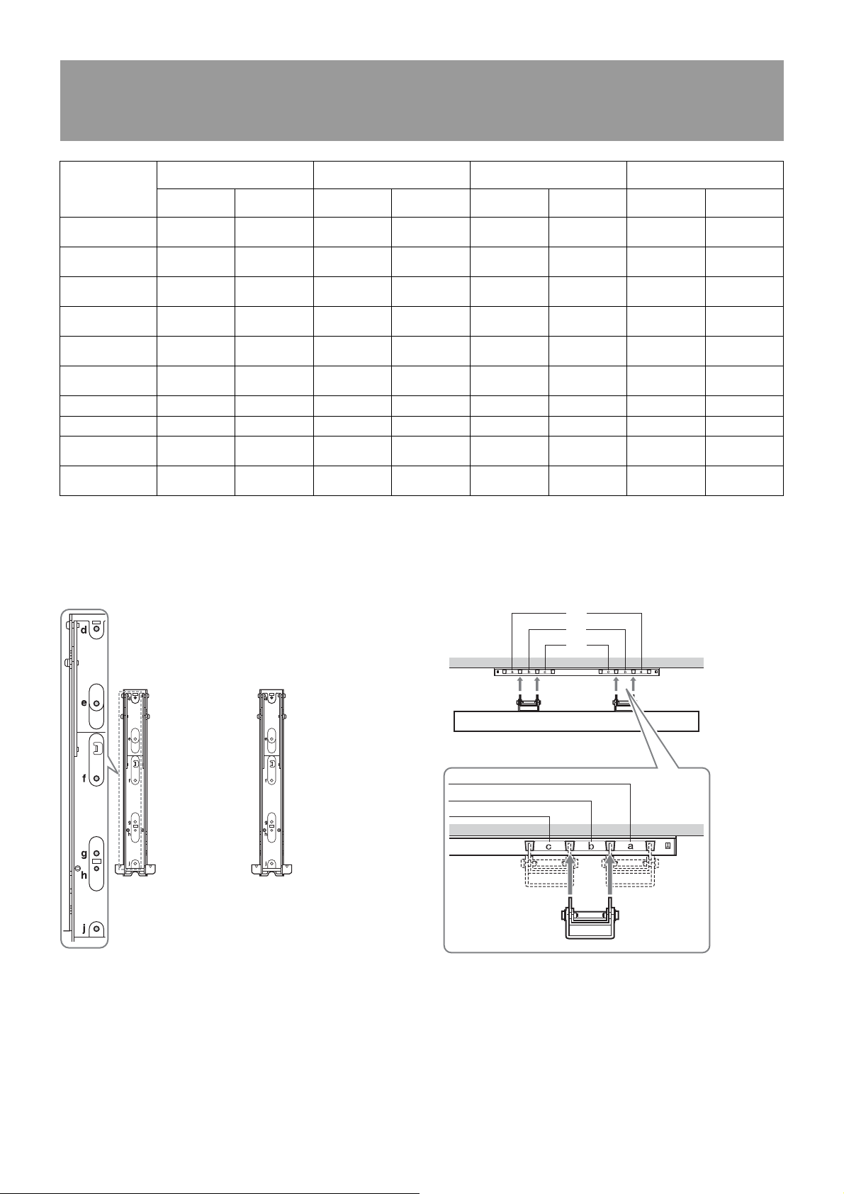
Screw and Hook locations diagram/table
Screw location
When installing the Mounting Hook on the TV.
Hook location
When installing the TV onto the Base Bracket.
c
a
b
Model Name
XBR-75X900E
KD-75X9000E
XBR-65X900E
KD-65X9000E
XBR-55X900E
KD-55X9000E
XBR-49X900E
KD-49X9000E
XBR-75X850E
KD-75X8500E
XBR-65X850E
KD-65X8500E
KD-55X8500E e, g c e, g c e, g c e, g c
XBR-55X800E e, g b e, g b e, j c e, j c
XBR-49X800E
KD-49X8000E
XBR-43X800E
KD-43X8000E
A: Landscape, -20° leaning B: Landscape, +60° leaning C: Portrait, no leaning D: Portrait, +20° leaning
Screw
location
d, j a — — d, j a — —
d, g b — — d, g b — —
d, g b — — d, g b — —
f, j c — — f, j c — —
d, gae, ja————
e, j b d, g b d, g b d, g b
f, j c f, j c e, g c e, g c
————f, gcf, gc
Hook
location
Screw
location
Hook
location
Screw
location
Hook
location
Screw
location
Hook
location
20 (GB)
Page 21

Page 22
Nous vous remercions d’avoir fait
l’acquisition de ce produit.
À l’attention des clients
L’installation de ce produit exige un certain savoirfaire. Veillez à confier l’installation à des
détaillants Sony ou à des installateurs agréés et
portez une attention particulière aux consignes de
sécurité pendant l’installation. Sony ne saurait
être tenue responsable de tout dommage ou de
toute blessure découlant d’une mauvaise
utilisation ou d’une installation incorrecte, ou
encore de l’installation d’un produit autre que
celui spécifié. Vos droits prévus par la loi (le cas
échéant) ne sont pas affectés.
AVERTISSEMENT
Le non-respect des consignes de sécurité ou
l’utilisation incorrecte de ce produit peut provoquer
un incendie ou des blessures graves.
Ce mode d’emploi indique comment manipuler le
produit correctement et contient des précautions
essentielles à prendre pour éviter tout accident. Lisez
attentivement ce mode d’emploi et veillez à utiliser le
produit correctement. Conservez ce mode d’emploi
pour toute référence ultérieure.
ATTENTION
Produits spécifiés
Les produits suivants sont susceptibles d’être
modifiés sans avis préalable, de ne plus être en
stock ou de ne plus être fabriqués.
Certains modèles ne sont pas disponibles dans
toutes les régions.
XBR-75X900E
XBR-65X900E
XBR-55X900E
XBR-49X900E
XBR-75X850E
XBR-65X850E
XBR-55X800E
XBR-49X800E
Téléviseur couleur ACL
XBR-43X800E
KD-75X9000E
KD-65X9000E
KD-55X9000E
KD-49X9000E
KD-75X8500E
KD-65X8500E
KD-55X8500E
KD-49X8000E
KD-43X8000E
À l’attention des détaillants Sony
L’installation de ce produit exige un certain savoirfaire. Lisez ce mode d’emploi attentivement afin de
procéder à l’installation en toute sécurité. Sony ne
saurait être tenue responsable de tout dommage ou
de toute blessure découlant d’une manipulation
inadéquate ou d’une installation incorrecte. Une fois
l’installation terminée, veuillez remettre ce manuel
au client.
Sécurité
Les produits Sony sont conçus pour vous offrir le
maximum de sécurité. Toutefois, si les produits sont
utilisés de façon incorrecte, ils peuvent entraîner des
blessures graves en provoquant un incendie ou une
électrocution, ou encore le basculement ou la chute
de l’appareil. Veillez à observer les consignes de
sécurité préconisées pour éviter de tels accidents.
2 (FR)
Page 23

Il existe 4 types d’installation. Il pourrait être impossible d’installer certains types de téléviseurs. Vérifiez les
points suivants et installez votre téléviseur de manière adéquate.
Il n’est pas possible d’installer l’ensemble de support d’adaptateur CA SU-AH1.
A : Paysage, inclinaison -20° B : Paysage, inclinaison +60° C : Portrait, aucune
inclinaison
D : Portrait, inclinaison +20°
Pour installer le téléviseur au mur, le support de fixation murale SU-WL500 est nécessaire. Les vis et les pièces
d’espacement indiquées ci-dessous sont également nécessaires, selon le type d’installation.
Pour obtenir plus de détails/les modalités et conditions, communiquez avec un représentant commercial pour
utilisation professionnelle.
Modèle de téléviseur
XBR-75X900E KD-75X9000E
XBR-65X900E
XBR-55X900E
XBR-49X900E
KD-65X9000E
KD-55X9000E
KD-49X9000E
Type d’installation
A
C
A
C
*1
Pièce d’espacement
*2
Support de fixation murale
Modèle Qté
FR
Français
XBR-75X850E KD-75X8500E
XBR-65X850E
XBR-55X800E
XBR-49X800E
XBR-43X800E KD-43X8000E
*1
Vous ne pouvez pas installer un téléviseur d’un type autre que ceux indiqués.
*2
Pour les téléviseurs avec , les éléments suivants sont nécessaires.
KD-65X8500E
KD-55X8500E
KD-49X8000E
A
B*3
A
B
C
D
A*5
B*5
C
D
C
D
*4
*4
*5
*5
*5
*5
SU-WL500 1
Pièce d’espacement : une rondelle avec diamètre extérieur de 18 mm, diamètre intérieur de 10 mm et
épaisseur de 2 mm (Numéro de pièce SONY 7-688-000-32) × 20
Vis : PSW M6 × 25 mm (Numéro de pièce SONY 4-577-326-01) × 4 (1 emballage)
*3
Réglez la luminosité à Standard ou Personnalisée 45 et inférieure.
*4
Réglez la luminosité du KD-55X8500E à Standard ou Personnalisée 30 et inférieure.
*5
Réglez la luminosité à Standard ou Personnalisée 35 et inférieure.
3 (FR)
Page 24
AVERTISSEMENT
Unité : mm (pouces)
300
(11
7
/8)
100
(4)
100
(4)
100
(4)
Unité : mm (pouces)
300
(11
7
/8)
100
(4)
100
(4)
100
(4)
Le non-respect des consignes suivantes peut
être fatal ou entraîner des blessures graves en
provoquant un incendie ou une électrocution,
ou encore le basculement ou la chute de
l’appareil.
Veillez à lire toutes les consignes de sécurité
indiquées dans le mode d’emploi du SU-WL500.
N’utilisez PAS le SU-WL450 pour une installation de la
manière indiquée dans ce manuel.
Prévoyez un espace suffisant autour
du téléviseur.
L’illustration suivante vous indique l’espace requis
autour du téléviseur.
Assurez-vous d’installer le téléviseur dans
l’orientation indiquée dans l’illustration suivante.
Paysage
N’obstruez pas les orifices de
ventilation du téléviseur.
Si vous obstruez les orifices de ventilation avec des
rubans adhésifs ou d’autres objets, le téléviseur
pourrait surchauffer et provoquer un incendie.
Autres
• Lors de l’installation dans l’orientation portrait,
seules les prises d’entrée/de sortie suivantes sont
disponibles :
– HDMI IN 1/2/3/4 (Prise en charge de la résolution
4K, compatible HDCP 2.2)
– DIGITAL AUDIO OUT (OPTICAL)
–AUDIO OUT / (Mini-prise stéréo)
– USB 1/2, USB 3
– LAN
– HDMI1 AUDIO IN (Il pourrait n’y avoir aucune
prise, selon le pays ou la région.)
• Si vous couvrez la DEL d’éclairage et la zone à
proximité avec des rubans adhésifs ou d’autres
objets, l’état du téléviseur ne pourra pas être
reconnu et la télécommande risque de ne pas
fonctionner.
• Lors du déplacement du téléviseur, tenez-le dans
l’orientation paysage et veillez à ne pas le laisser
tomber pendant l’installation. N’exercez aucune
pression excessive sur le téléviseur, car cela
pourrait le déformer.
Portrait
4 (FR)
Page 25
A : paysage, inclinaison -20°
Étape 1 :
Vérification des pièces
requises pour
l’installation
Suivez l’étape 1 dans le mode d’emploi du SU-WL500
pour vérifier les pièces.
Étape 2 :
Choix de
l’emplacement
d’installation
Suivez l’étape 2 dans le mode d’emploi du SU-WL500
pour choisir l’emplacement d’installation. Reportezvous à la page 18 de ce manuel pour consulter le
tableau de dimensions d’installation des téléviseurs.
Étape 4 :
Préparation de
l’installation du
téléviseur
Retirez le support s’il est installé
1
sur le téléviseur.
Déposez le téléviseur et placez un chiffon doux
sous le téléviseur pour protéger l’écran du
téléviseur.
XBR-75X900E/XBR-65X900E/XBR-55X900E/
XBR-49X900E/XBR-75X850E/XBR-65X850E/
XBR-55X800E/KD-75X9000E/KD-65X9000E/
KD-55X9000E/KD-49X9000E/KD-75X8500E/
KD-65X8500E/KD-55X8500E
Étape 3 :
Installation au mur du
support de base
Suivez l’étape 3 dans le mode d’emploi du SU-WL500
pour installer le support de base.
XBR-49X800E/KD-49X8000E
5 (FR)
Page 26

Si vous utilisez un tournevis électrique, réglez son
Crochet de montage
Vis
*1, *2
Pièce
d’espacement
*1, *2
10 mm (13/32 po)
couple à 2 N·m {20 kgf·cm} environ.
Ne soulevez pas le crochet de montage avant
d’avoir convenablement serré les vis (deux vis de
chacun des côtés gauche/droit). Vous risqueriez
de déformer le crochet de montage ou le boîtier
du téléviseur.
Retirez les vis situées à l’arrière
2
du téléviseur.
XBR-75X900E/XBR-65X900E/XBR-55X900E/
XBR-49X900E/XBR-65X850E/KD-75X9000E/
KD-65X9000E/KD-55X9000E/KD-49X9000E/
KD-65X8500E/KD-55X8500E
En vous reportant au Schéma/
3
tableau des emplacements des
crochets et des vis de la page 20,
déterminez les emplacements
des vis et fixez le crochet de
montage à l’arrière du
téléviseur.
Fixez temporairement le crochet de montage
à l’arrière du téléviseur à l’aide des quatre vis
(*1, *2)
.
Assurez-vous que les deux vis sont serrées
convenablement, au même couple, à l’arrière
du téléviseur.
XBR-75X850E/KD-75X8500E
*1
Nécessite 5 pièces d’espacement (non
fournies) et vis PSW M6 × 25 mm (non
fournies) :
XBR-75X900E/XBR-75X850E/XBR-65X850E/
KD-75X9000E/KD-75X8500E/KD-65X8500E/
KD-55X8500E
*2
Aucune pièce d’espacement n’est
nécessaire, mais les vis PSW 6 × 16 mm sont
nécessaires (fournies) :
XBR-65X900E/XBR-55X900E/XBR-49X900E/
XBR-55X800E/XBR-49X800E/KD-65X9000E/
KD-55X9000E/KD-49X9000E/KD-49X8000E
6 (FR)
Page 27
Réglez l’angle du crochet de
Remarques
ATTENTIO N
Clé hexagonale
AVERTISSEMENT
Remarques
4
montage avec la clé hexagonale
fournie.
Effectuez l’opération en suivant les étapes et
. Vérifiez que la vis est fixée solidement
dans la base de bras du crochet de montage
(sur les côtés gauche et droit).
Retirez les 2 vis de la base de bras du
crochet de montage (sur les côtés gauche et
droit) et déterminez les trous de vis pour
l’angle (20°) souhaité pour le changement.
Placez les trous de vis du bras supérieur et
du bras inférieur dans un angle adéquat,
insérez les vis retirées à l’étape dans les
trous, puis fixez les deux bras.
Étape 5 :
Installation du
téléviseur au mur
Veillez à terminer l’installation avant de brancher
le cordon d’alimentation CA à la prise murale. Si le
cordon d’alimentation CA se coince sous ou entre
des pièces de l’appareil, cela peut provoquer un
court-circuit ou une électrocution.
Veillez à ne pas trébucher sur le cordon
d’alimentation CA ou sur le téléviseur, car vous
pourriez vous blesser.
Branchez au téléviseur le cordon
1
d’alimentation CA et le(s)
câble(s) de raccordement fournis
avec le téléviseur.
Branchez le cordon d’alimentation CA et le(s)
câble(s) de raccordement aux connecteurs
situés à l’arrière du téléviseur. Pour plus
d’informations sur la manière de brancher le
cordon d’alimentation CA et le(s) câble(s) de
raccordement, reportez-vous au mode d’emploi
du téléviseur.
• Vérifiez que l’angle ajusté des deux bras est
identique.
• Vérifiez que les deux bras sont vissés solidement.
• Veillez à ne pas vous coincer les doigts pendant le
réglage de l’angle.
• Vous ne pouvez pas raccorder les câbles au
téléviseur une fois que celui-ci est installé sur le
support de base.
• Confiez l’acheminement du câble dans le mur à un
installateur agréé.
7 (FR)
Page 28

Installez le téléviseur sur le
AVERTISSEMENT
Support de base
Crochet de montage
Remarque
Vis
(+BVST4 × 12)
AVERTISSEMENT
Veillez à serrer fermement la vis de fixation.
Sinon, le téléviseur pourrait tomber s’il est
poussé vers le haut et provoquer des
blessures.
2
support de base.
En vous reportant au Schéma/tableau des
emplacements des crochets et des vis de la
page 20, déterminez les emplacements du
support de base destinés à accrocher les
crochets supérieurs du crochet de montage.
Saisissez convenablement le téléviseur avec
les deux mains et alignez-le délicatement sur
le mur.
• Veillez à ce qu’au moins deux personnes
soutiennent le téléviseur pour le déplacer.
• Lors du déplacement du téléviseur, tenez-le dans
l’orientation paysage et veillez à ne pas le laisser
tomber pendant l’installation. N’exercez aucune
pression excessive sur le téléviseur, car cela
pourrait le déformer.
Fixez convenablement le
3
téléviseur et le support de base
à l’aide de la vis fournie avec le
SU-WL500 (+BVST4 × 12).
Si vous utilisez un tournevis électrique, réglez son
couple à 1,5 N·m {15 kgf·cm} environ.
Vérification de la bonne
installation
Suivez les instructions dans le mode d’emploi du
SU-WL500 pour effectuer la vérification.
Lors du retrait du
8 (FR)
téléviseur
Suivez les instructions dans le mode d’emploi du
SU-WL500 pour effectuer le retrait.
Page 29
B : paysage, inclinaison +60°
Étape 1 :
Vérification des pièces
requises pour
l’installation
Suivez l’étape 1 dans le mode d’emploi du SU-WL500
pour vérifier les pièces.
Étape 2 :
Choix de
l’emplacement
d’installation
Suivez l’étape 2 dans le mode d’emploi du SU-WL500
pour choisir l’emplacement d’installation. Reportezvous à la page 18 de ce manuel pour consulter le
tableau de dimensions d’installation des téléviseurs.
Étape 4 :
Préparation de
l’installation du
téléviseur
Retirez le support s’il est installé
1
sur le téléviseur.
Déposez le téléviseur et placez un chiffon doux
sous le téléviseur pour protéger l’écran du
téléviseur.
XBR-75X850E/XBR-65X850E/XBR-55X800E/
KD-75X8500E/KD-65X8500E/KD-55X8500E
Étape 3 :
Installation au mur ou
montage du support de
base
Suivez l’étape 3 dans le mode d’emploi du SU-WL500
pour installer le support de base.
XBR-49X800E/KD-49X8000E
Si vous utilisez un tournevis électrique, réglez son
couple à 2 N·m {20 kgf·cm} environ.
Ne soulevez pas le crochet de montage avant
d’avoir convenablement serré les vis (deux vis de
chacun des côtés gauche/droit). Vous risqueriez
de déformer le crochet de montage ou le boîtier
du téléviseur.
9 (FR)
Page 30

Retirez les vis situées à l’arrière
Crochet de montage
Vis
*1, *2
Pièce
d’espacement
*1, *2
10 mm (13/32 po)
2
du téléviseur.
XBR-65X850E/KD-65X8500E/KD-55X8500E
XBR-75X850E/KD-75X8500E
En vous reportant au Schéma/
3
tableau des emplacements des
crochets et des vis de la page 20,
déterminez les emplacements
des vis et fixez le crochet de
montage à l’arrière du
téléviseur.
Fixez temporairement le crochet de montage
à l’arrière du téléviseur à l’aide des quatre vis
(*1, *2)
.
Assurez-vous que les deux vis sont serrées
convenablement, au même couple, à l’arrière
du téléviseur.
*1
Nécessite 5 pièces d’espacement (non
fournies) et vis PSW M6 × 25 mm (non
fournies) :
XBR-65X850E/KD-65X8500E/KD-55X8500E
*2
Aucune pièce d’espacement n’est
nécessaire, mais les vis PSW 6 × 16 mm sont
nécessaires (fournies) :
XBR-75X850E/XBR-55X800E/XBR-49X800E/
KD-75X8500E/KD-49X8000E
10 (FR)
Page 31
Vérifiez que la vis est fixée
Remarque
AVERTISSEMENT
Remarques
4
solidement dans la base de bras
du crochet de montage (sur les
côtés gauche et droit).
Vérifiez que les deux bras sont vissés solidement.
Étape 5 :
Installation du
téléviseur au mur
Veillez à terminer l’installation avant de brancher
le cordon d’alimentation CA à la prise murale. Si le
cordon d’alimentation CA se coince sous ou entre
des pièces de l’appareil, cela peut provoquer un
court-circuit ou une électrocution.
Veillez à ne pas trébucher sur le cordon
d’alimentation CA ou sur le téléviseur, car vous
pourriez vous blesser.
Branchez au téléviseur le cordon
1
d’alimentation CA et le(s)
câble(s) de raccordement fournis
avec le téléviseur.
Branchez le cordon d’alimentation CA et le(s)
câble(s) de raccordement aux connecteurs
situés à l’arrière du téléviseur. Pour plus
d’informations sur la manière de brancher le
cordon d’alimentation CA et le(s) câble(s) de
raccordement, reportez-vous au mode d’emploi
du téléviseur.
• Vous ne pouvez pas raccorder les câbles au
téléviseur une fois que celui-ci est installé sur le
support de base.
• Confiez l’acheminement du câble dans le mur à un
installateur agréé.
11 (FR)
Page 32
Installez le téléviseur sur le
AVERTISSEMENT
Support de base
Crochet de montage
Remarque
Vis
(+BVST4 × 12)
AVERTISSEMENT
Veillez à serrer fermement la vis de fixation.
Sinon, le téléviseur pourrait tomber s’il est
poussé vers le haut et provoquer des
blessures.
2
support de base.
En vous reportant au Schéma/tableau des
emplacements des crochets et des vis de la
page 20, déterminez les emplacements du
support de base destinés à accrocher les
crochets supérieurs du crochet de montage.
Saisissez convenablement le téléviseur avec
les deux mains et alignez-le délicatement sur
le mur.
• Veillez à ce qu’au moins deux personnes
soutiennent le téléviseur pour le déplacer.
• Lors du déplacement du téléviseur, tenez-le dans
l’orientation paysage et veillez à ne pas le laisser
tomber pendant l’installation. N’exercez aucune
pression excessive sur le téléviseur, car cela
pourrait le déformer.
Fixez convenablement le
3
téléviseur et le support de base
à l’aide de la vis fournie avec le
SU-WL500 (+BVST4 × 12).
Si vous utilisez un tournevis électrique, réglez son
couple à 1,5 N·m {15 kgf·cm} environ.
Vérification de la bonne
installation
Suivez les instructions dans le mode d’emploi du
SU-WL500 pour effectuer la vérification.
Lors du retrait du
12 (FR)
téléviseur
Suivez les instructions dans le mode d’emploi du
SU-WL500 pour effectuer le retrait.
Page 33

C : portrait, aucune inclinaison /
D : portrait, inclinaison +20°
Étape 1 :
Vérification des pièces
requises pour
l’installation
Suivez l’étape 1 dans le mode d’emploi du SU-WL500
pour vérifier les pièces.
Étape 2 :
Choix de
l’emplacement
d’installation
Suivez l’étape 2 dans le mode d’emploi du SU-WL500
pour choisir l’emplacement d’installation. Reportezvous à la page 19 de ce manuel pour consulter le
tableau de dimensions d’installation des téléviseurs.
Étape 4 :
Préparation de
l’installation du
téléviseur
Retirez le support s’il est installé
1
sur le téléviseur.
Déposez le téléviseur et placez un chiffon doux
sous le téléviseur pour protéger l’écran du
téléviseur.
XBR-75X900E/XBR-65X900E/XBR-55X900E/
XBR-49X900E/XBR-65X850E/XBR-55X800E/
KD-75X9000E/KD-65X9000E/KD-55X9000E/
KD-49X9000E/KD-65X8500E/KD-55X8500E
Étape 3 :
Installation au mur ou
montage du support de
base
Suivez l’étape 3 dans le mode d’emploi du SU-WL500
pour installer le support de base.
XBR-49X800E/XBR-43X800E/KD-49X8000E/
KD-43X8000E
13 (FR)
Page 34

Si vous utilisez un tournevis électrique, réglez son
Vis
(+PSW6 × 25)
(non fournie)
Crochet
de
montage
Pièce
d’espacement × 5
(non fournie)
10 mm (13/32 po)
couple à 2 N·m {20 kgf·cm} environ.
Ne soulevez pas le crochet de montage avant
d’avoir convenablement serré les vis (deux vis de
chacun des côtés gauche/droit). Vous risqueriez
de déformer le crochet de montage ou le boîtier
du téléviseur.
Retirez les vis situées à l’arrière
2
du téléviseur.
XBR-75X900E/XBR-65X900E/XBR-55X900E/
XBR-49X900E/XBR-65X850E/KD-75X9000E/
KD-65X9000E/KD-55X9000E/KD-49X9000E/
KD-65X8500E/KD-55X8500E
En vous reportant au Schéma/
3
tableau des emplacements des
crochets et des vis de la page 20,
déterminez les emplacements
des vis et fixez le crochet de
montage à l’arrière du
téléviseur.
Fixez temporairement le crochet de montage
à l’arrière du téléviseur à l’aide des quatre vis
(+PSW6 × 25).
Assurez-vous que les deux vis sont serrées
convenablement, au même couple, à l’arrière
du téléviseur.
14 (FR)
Page 35

Vérifiez que la vis est fixée
Remarques
AVERTISSEMENT
Remarques
4
solidement dans la base de bras
du crochet de montage (sur les
côtés gauche et droit).
• Lors de l’installation dans l’orientation portrait,
assurez-vous que l’angle du crochet de montage
soit à 0 degré. N’utilisez pas d’autres angles.
• Vérifiez que les deux bases de bras sont vissées
solidement.
Étape 5 :
Installation du
téléviseur au mur
Veillez à terminer l’installation avant de brancher
le cordon d’alimentation CA à la prise murale. Si le
cordon d’alimentation CA se coince sous ou entre
des pièces de l’appareil, cela peut provoquer un
court-circuit ou une électrocution.
Veillez à ne pas trébucher sur le cordon
d’alimentation CA ou sur le téléviseur, car vous
pourriez vous blesser.
Branchez au téléviseur le cordon
1
d’alimentation CA et le(s)
câble(s) de raccordement fournis
avec le téléviseur.
Branchez le cordon d’alimentation CA et le(s)
câble(s) de raccordement aux connecteurs
situés à l’arrière du téléviseur. Pour plus
d’informations sur la manière de brancher le
cordon d’alimentation CA et le(s) câble(s) de
raccordement, reportez-vous au mode d’emploi
du téléviseur.
• Vous ne pouvez pas raccorder les câbles au
téléviseur une fois que celui-ci est installé sur le
support de base.
• Confiez l’acheminement du câble dans le mur à un
installateur agréé.
15 (FR)
Page 36

Installez le téléviseur sur le
AVERTISSEMENT
Support de
base
Crochet de montage
Support de base
Crochet de montage
2
support de base.
En vous reportant au Schéma/tableau des
emplacements des crochets et des vis de la
page 20, déterminez les emplacements du
support de base destinés à accrocher les
crochets supérieurs du crochet de montage.
Saisissez convenablement le téléviseur avec
les deux mains et alignez-le délicatement sur
le mur.
• Veillez à ce qu’au moins deux personnes
soutiennent le téléviseur pour le déplacer.
• Lors du déplacement du téléviseur, tenez-le dans
l’orientation paysage et veillez à ne pas le laisser
tomber pendant l’installation. N’exercez aucune
pression excessive sur le téléviseur, car cela
pourrait le déformer.
C : Portrait, aucune inclinaison
D : Portrait, inclinaison +20°
16 (FR)
Page 37

Fixez convenablement le
Vis
(+BVST4 × 12)
Remarque
Vis
(+BVST4 × 12)
AVERTISSEMENT
Veillez à serrer fermement la vis de fixation.
Sinon, le téléviseur pourrait tomber s’il est
poussé vers le haut et provoquer des
blessures.
3
téléviseur et le support de base
à l’aide de la vis fournie avec le
SU-WL500 (+BVST4 × 12).
C : Portrait, aucune inclinaison
D : Portrait, inclinaison +20°
Si vous utilisez un tournevis électrique, réglez son
couple à 1,5 N·m {15 kgf·cm} environ.
Vérification de la bonne
installation
Suivez les instructions dans le mode d’emploi du
SU-WL500 pour effectuer la vérification.
Lors du retrait du
téléviseur
Suivez les instructions dans le mode d’emploi du
SU-WL500 pour effectuer le retrait.
17 (FR)
Page 38

AVERTISSEMENT
Tableau des dimensions d’installation des
Point central de l’écran
téléviseurs
Le tableau ci-dessous indique les dimensions du téléviseur installé sur ce produit. Reportez-vous à ce tableau
pour choisir l’emplacement d’installation.
A : Paysage, inclinaison -20°
B : Paysage, inclinaison +60°
Unité : mm (pouces)
Longueur pour chaque angle de fixation
410
(16 1/4)
369
(14 5/8)
327
(12 7/8)
297
(11 3/4)
424
(16 3/4)
353
(14)
322
(12 3/4)
330
(13)
315
(12 1/2)
901
(35 1/2)
780
(30 3/4)
664
(26 1/4)
592
(23 3/8)
910
(35 7/8)
790
(31 1/8)
674
(26 5/8)
675
(26 5/8)
603
(23 3/4)
————
————
————
————
547
(21 5/8)
411
4)
6 1/
(1
507
(20)
467
(18 1/2)
434
(17 1/8)
Nom du modèle
XBR-75X900E
KD-75X9000E
XBR-65X900E
KD-65X9000E
XBR-55X900E
KD-55X9000E
XBR-49X900E
KD-49X9000E
XBR-75X850E
KD-75X8500E
XBR-65X850E
KD-65X8500E
KD-55X8500E
XBR-55X800E
XBR-49X800E
KD-49X8000E
Dimensions de
l’écran
1674
(66)
1447
(57)
1228
(48 3/8)
1093
(43 1/8)
1677
(66 1/8)
1454
(57 1/4)
1232
(48 5/8)
1232
(48 5/8)
1096
(43 1/4)
959
(37 7/8)98(3 7/8)
830
(32 3/4)
707
(27 7/8)
631
(24 7/8)
968
(38 1/8)11(7/16)
840
(33 1/8)
717
(28 1/4)
716
(28 1/4)
640
(25 1/4)
103
(4 1/8)
161
(6 3/8)
213
(8 1/2)
121
(4 7/8)
187
(7 3/8)
147
(5 7/8)
151
(6)
Angle (20º) Angle (60º)
549
(21 5/8)
494
(19 1/2)
494
(19 1/2)
511
(20 1/8)
469
(18 1/2)
518
(20 1/2)
527
(20 3/4)
488
(19 1/4)
456
(18)
Certains modèles ne sont pas disponibles dans toutes les régions.
Les chiffres indiqués dans le tableau ci-dessus peuvent varier légèrement selon l’installation.
840
(33 1/8)
729
(28 3/4)
623
(24 5/8)
623
(24 5/8)
557
(22)
527
(20 3/4)
456
(18)
403
(15 7/8)
406
(16)
369
(14 5/8)
109
(4 3/8)
110
(4 3/8)
123
(4 7/8)
117
(4 5/8)
117
(4 5/8)
Le mur sur lequel vous installez le téléviseur doit pouvoir supporter un poids équivalent à au moins quatre fois
celui du téléviseur.
Pour connaître son poids, reportez-vous au mode d’emploi du téléviseur.
18 (FR)
Page 39

C : Portrait, aucune inclinaison
AVERTISSEMENT
Point central de l’écran
D : Portrait, inclinaison +20°
Unité : mm (pouces)
Longueur pour chaque angle de fixation
Angle (0º) Angle (20º)
1008
(39 3/4)
845
(33 3/8)
735
(29)
818
(32 1/4)
848
(33 1/2)
787
(31)
837
(33)
719
(28 3/8)
703
(27 3/4)
Nom du modèle
XBR-75X900E
KD-75X9000E
XBR-65X900E
KD-65X9000E
XBR-55X900E
KD-55X9000E
XBR-49X900E
KD-49X9000E
XBR-65X850E
KD-65X8500E
KD-55X8500E
XBR-55X800E
XBR-49X800E
KD-49X8000E
XBR-43X800E
KD-43X8000E
Dimensions de l’écran Dimensions au centre de l’écran
959
(37 7/8)
830
(32 3/4)
707
(27 7/8)
631
(24 7/8)
840
(33 1/8)
717
(28 1/4)
716
(28 1/4)
640
(25 1/4)
565
(22 1/4)
1674
(66)
1447
(57)
1228
(48 3/8)
1093
(43 1/8)
1454
(57 1/4)
1232
(48 5/8)
1232
(48 5/8)
1096
(43 1/4)
964
(38)
171
(6 3/4)
121
(4 7/8)
121
(4 7/8)
271
(10 3/4)
121
(4 7/8)
171
(6 3/4)
221
(8 3/4)
171
(6 3/4)
221
(8 3/4)
130
(5 1/8)
69
(2 3/4)
7
(9/32)
102
(4 1/8)
145
(5 3/4)
30
(1 3/16)
70
(2 7/8)
166
(6 5/8)
129
(5 1/8)
354
(14)
351
(13 7/8)
351
(13 7/8)
218
(8 5/8)
281
(11 1/8)
336
3 1/4)
(1
295
(11 5/8)
161
(6 3/8)
161
(6 3/8)
Certains modèles ne sont pas disponibles dans toutes les régions.
Les chiffres indiqués dans le tableau ci-dessus peuvent varier légèrement selon l’installation.
136
(5 3/8)
130
(5 1/8)
130
(5 1/8)
132
(5 1/4)
110
(4 3/8)
123
(4 7/8)
127
(5)
127
(5)
127
(5)
——
——
——
——
518
(20 1/2)
451
(17 7/8)
448
(17 3/4)
409
(16 1/8)
367
(14 1/2)
1369
(54)
1162
(45 3/4)
1162
(45 3/4)
1034
(40 3/4)
909
(35 7/8)
Le mur sur lequel vous installez le téléviseur doit pouvoir supporter un poids équivalent à au moins quatre fois
celui du téléviseur.
Pour connaître son poids, reportez-vous au mode d’emploi du téléviseur.
19 (FR)
Page 40
Schéma/tableau des emplacements des crochets et
Emplacement des vis
En cas d’installation du crochet de montage sur le
téléviseur.
Emplacement du crochet
En cas d’installation du téléviseur sur le support de
base.
c
a
b
des vis
A : Paysage, inclinaison
Nom du modèle
XBR-75X900E
KD-75X9000E
XBR-65X900E
KD-65X9000E
XBR-55X900E
KD-55X9000E
XBR-49X900E
KD-49X9000E
XBR-75X850E
KD-75X8500E
XBR-65X850E
KD-65X8500E
KD-55X8500E e, g c e, g c e, g c e, g c
XBR-55X800E e, g b e, g b e, j c e, j c
XBR-49X800E
KD-49X8000E
XBR-43X800E
KD-43X8000E
Emplacement
des vis
-20°
Emplacement
du crochet
d, j a — — d, j a — —
d, g b — — d, g b — —
d, g b — — d, g b — —
f, j c — — f, j c — —
d, gae, ja————
e, j b d, g b d, g b d, g b
f, j c f, j c e, g c e, g c
————f, gcf, gc
B: Paysage, inclinaison
Emplacement
des vis
+60°
Emplacement
du crochet
C : Portrait, aucune
inclinaison
Emplacement
des vis
Emplacement
du crochet
D : Portrait, inclinaison
Emplacement
des vis
+20°
Emplacement
du crochet
20 (FR)
Page 41

Page 42

Gracias por comprar este producto.
Información para los clientes
Para la instalación de este producto se requieren
conocimientos previos. Asegúrese de contratar
para la instalación a un distribuidor o a un
contratista Sony autorizado y preste especial
atención a la seguridad durante la instalación.
Sony no se hace responsable de los daños o
lesiones causados por la mala utilización, la
instalación incorrecta o la instalación de cualquier
producto que no sea el especificado. Esto no
afecta sus derechos de carácter legal (en caso de
haberlos).
ADVERTENCIA
Si no se siguen las medidas de seguridad o si el
producto se utiliza incorrectamente, podrían
producirse lesiones graves o un incendio.
Este manual muestra la manera correcta de
manipular el producto, así como las precauciones
importantes necesarias para evitar accidentes. Lea
detenidamente este manual para utilizar el producto
de manera correcta. Conserve este manual para
poder consultarlo en el futuro.
PRECAUCIÓN
Productos especificados
Los siguientes productos están sujetos a cambios
sin previo aviso, podrían estar agotados o haberse
dejado de fabricar.
Es posible que algunos modelos no se encuentren
en algunas regiones.
XBR-75X900E
XBR-65X900E
XBR-55X900E
XBR-49X900E
XBR-75X850E
XBR-65X850E
XBR-55X800E
XBR-49X800E
LCD Color TV
XBR-43X800E
KD-75X9000E
KD-65X9000E
KD-55X9000E
KD-49X9000E
KD-75X8500E
KD-65X8500E
KD-55X8500E
KD-49X8000E
KD-43X8000E
Información para los distribuidores de Sony
Para la instalación de este producto se requieren
conocimientos previos. Lea detenidamente este
manual para realizar la instalación de manera segura.
Sony no se responsabiliza de ningún daño o lesión
provocados por la manipulación o instalación
incorrecta. Entregue este manual al cliente después
de la instalación.
Seguridad
Los productos de Sony están diseñados pensando en
la seguridad. Sin embargo, si los productos se utilizan
de manera incorrecta, pueden producirse lesiones
graves a causa de un incendio o una descarga
eléctrica, o al volcarse o caerse el producto. Para
evitar tales accidentes, asegúrese de respetar las
precauciones de seguridad.
2 (ES)
Page 43
Hay 4 tipos de instalaciones. Puede que no sea posible instalarlo en algunos tipos de televisores. Revise la
siguiente información e instale su televisor de manera apropiada.
No se puede instalar el kit de soporte del adaptador de CA SU-AH1.
A: Horizontal, inclinación de
-20°
B: Horizontal, inclinación de +60° C: Vertical, sin inclinación D: Vertical, inclinación de
+20°
Se necesita el Soporte de montaje mural SU-WL500 para instalar el televisor en la pared. Los tornillos y
separadores que se enumeran a continuación también son necesarios según la forma de instalación.
Para obtener más detalles acerca de los términos y condiciones, contacte al representante comercial para el uso
profesional.
Modelo de televisor
XBR-75X900E KD-75X9000E
XBR-65X900E
XBR-55X900E
XBR-49X900E
KD-65X9000E
KD-55X9000E
KD-49X9000E
Instalación tipo
A
C
A
C
*1
Separador
*2
Soporte de montaje mural
Modelo Cant.
ES
Español
XBR-75X850E KD-75X8500E
XBR-65X850E
XBR-55X800E
XBR-49X800E
XBR-43X800E KD-43X8000E
*1
No puede instalar otros televisores que no sean los tipos de televisores indicados.
*2
Para el televisor con , se necesita lo siguiente.
KD-65X8500E
KD-55X8500E
KD-49X8000E
A
B*3
A
B
C
D
A*5
B*5
C
D
C
D
*4
*4
*5
*5
*5
*5
SU-WL500 1
Separador: una arandela con un diámetro exterior de 18 mm, un diámetro interno de 10 mm y un espesor de
2 mm (Número de parte SONY 7-688-000-32) × 20
Tornillo: PSW M6 de 25 mm (Número de parte SONY 4-577-326-01) × 4 (1 pqt.)
*3
Realice el ajuste del brillo a Estándar o Personalizado en 45 e inferior.
*4
Realice el ajuste del brillo del KD-55X8500E a Estándar o Personalizado en 30 e inferior.
*5
Realice el ajuste del brillo a Estándar o Personalizado en 35 e inferior.
3 (ES)
Page 44

ADVERTENCIA
Unidad: mm (pulgadas)
300
(11
7
/8)
100
(4)
100
(4)
100
(4)
Unidad: mm (pulgadas)
300
(11
7
/8)
100
(4)
100
(4)
100
(4)
Si no se tienen en cuenta las siguientes
precauciones, pueden producirse lesiones
graves o incluso de muerte a causa de un
incendio o una descarga eléctrica, o al volcarse
o caerse el producto.
Lea detenidamente toda la información sobre
seguridad descrita en el manual de instrucciones del
SU-WL500.
NO utilice el SU-WL450 para la instalación en la
manera indicada en este manual.
Deje espacio suficiente alrededor
del televisor.
La siguiente ilustración muestra el espacio requerido
alrededor del televisor.
Asegúrese de instalar el televisor en la orientación
que se muestra en la siguiente ilustración.
Horizontal
No bloquee los huecos de
ventilación del televisor.
Si bloquea los huecos de ventilación con cintas
adhesivas u otros objetos, se acumulará calor dentro
del equipo y esto podrá provocar un incendio.
Otras
• Cuando instale el televisor en posición vertical,
solo las siguientes entradas/salidas estarán
disponibles:
– HDMI IN 1/2/3/4 (Admite resolución 4K,
compatible con HDCP 2.2)
– DIGITAL AUDIO OUT (ÓPTICA)
–AUDIO OUT / (miniconector estéreo)
– USB 1/2, USB 3
– LAN
– HDMI1 AUDIO IN (Puede que no haya toma
según el país o región).
• Si cubre la iluminación LED y sus alrededores con
cintas adhesivas u otros objetos, el estado del
televisor no podrá ser reconocido y es posible que
el control remoto no funcione.
• Cuando transporte el televisor, manténgalo en
posición horizontal y cuide que no se caiga cuando
lo instale. No aplique fuerza excesiva al televisor; si
no, podrá deformarse.
Vertical
4 (ES)
Page 45
A: horizontal, inclinación de -20°
Paso 1:
Revisión de las partes
requeridas para la
instalación
Siga el Paso 1 en el manual de instrucciones del SUWL500 para revisar las partes.
Paso 2:
Elección del lugar de
instalación
Siga el Paso 2 en el manual de instrucciones del
SU-WL500 para elegir el lugar de instalación.
Consulte página 18 de este manual a fin de revisar la
tabla de dimensiones para la instalación del televisor.
Paso 4:
Preparación para la
instalación del televisor
Quite el soporte si está instalado
1
en el televisor.
Recueste el televisor y coloque una tela suave
debajo de este para proteger su monitor.
XBR-75X900E/XBR-65X900E/XBR-55X900E/
XBR-49X900E/XBR-75X850E/XBR-65X850E/
XBR-55X800E/KD-75X9000E/KD-65X9000E/
KD-55X9000E/KD-49X9000E/KD-75X8500E/
KD-65X8500E/KD-55X8500E
Paso 3:
Instalación del soporte
en la pared
Siga el Paso 3 en el manual de instrucciones del
SU-WL500 para instalar el soporte.
XBR-49X800E/KD-49X8000E
Si utiliza un destornillador eléctrico, ajuste el par
de fijación aproximadamente 2 N·m {20 kgf·cm}.
No levante el gancho de soporte antes de que los
tornillos (dos tornillos para cada lado derecho/
izquierdo) queden ajustados. Esto puede
deformar el gancho de soporte o el gabinete del
televisor.
5 (ES)
Page 46

Quite los tornillos en la parte
Gancho de soporte
Tornillo
*1, *2
Separador
*1, *2
10 mm
(13/32 pulgadas)
2
posterior del televisor.
XBR-75X900E/XBR-65X900E/XBR-55X900E/
XBR-49X900E/XBR-65X850E/KD-75X9000E/
KD-65X9000E/KD-55X9000E/KD-49X9000E/
KD-65X8500E/KD-55X8500E
XBR-75X850E/KD-75X8500E
Consulte la tabla/diagrama de
3
ubicaciones de los tornillos y el
gancho en la página 20, para
determinar las posiciones de los
tornillos y ajustar el gancho de
soporte a la parte posterior del
televisor.
Para ajustar el gancho de soporte a la parte
posterior del televisor, utilice los cuatro
tornillos
Asegúrese de que ambos tornillos estén bien
ajustados con la misma fuerza de par de
fijación a la parte posterior del televisor.
(*1, *2)
.
*1
Requiere 5 separadores (no suministrados) y
tornillos PSW M6 × 25 mm (no
suministrados):
XBR-75X900E/XBR-75X850E/XBR-65X850E/
KD-75X9000E/KD-75X8500E/KD-65X8500E/
KD-55X8500E
*2
Los separadores no son necesarios, pero sí
los tornillos de PSW 6 × 16 mm
(suministrados):
XBR-65X900E/XBR-55X900E/XBR-49X900E/
XBR-55X800E/XBR-49X800E/KD-65X9000E/
KD-55X9000E/KD-49X9000E/KD-49X8000E
6 (ES)
Page 47

Ajuste el ángulo del gancho de
Notas
PRECAUCIÓN
Llave hexagonal
ADVERTENCIA
Notas
4
soporte con la llave hexagonal
suministrada.
Realice los siguientes y . Asegúrese de que
el tornillo ajuste de manera segura la base
del brazo al gancho de soporte (tanto izquierdo
como derecho).
Quite los 2 tornillos de la base del brazo
del gancho de soporte (tanto izquierdo como
derecho) y establezca los orificios de los
tornillos para el ángulo (20°) al que planea
cambiarlo.
Prepare los orificios de los tornillos del brazo
superior y el inferior en un ángulo
adecuado, coloque los tornillos que quitó en
el paso en los orificios, luego ajuste
ambos brazos.
Paso 5:
Instalación del televisor
a la pared
Asegúrese de haber completado la instalación
antes de enchufar el cable de alimentación de CA
a la toma de pared. Si el cable de alimentación de
CA queda atrapado debajo o entre los
componentes del equipo, podría producirse un
cortocircuito o una descarga eléctrica.
Tenga cuidado de no tropezar con el cable de
alimentación de CA o el televisor ya que podría
hacerse daño.
Conecte el cable de alimentación
1
de CA y los cables de conexión
suministrados junto con el
televisor.
Conecte el cable de alimentación de CA y los
cables de conexión a los conectores de la parte
posterior del televisor. Para obtener información
detallada sobre la conexión del cable de
alimentación de CA y de los cables de conexión,
consulte el manual de instrucciones del
televisor.
• Asegúrese de que los ángulos ajustados de ambos
brazos sean los mismos.
• Asegúrese de que ambos brazos queden ajustados
de manera segura.
• Tenga cuidado de que los dedos no le queden
atrapados mientras ajusta el ángulo.
• No es posible conectar los cables al televisor
después de instalarlo en el soporte.
• Asegúrese de encargar la instalación de los cables
en la pared a un contratista autorizado.
7 (ES)
Page 48

Instale el televisor en el soporte.
ADVERTENCIA
Soporte
Gancho de soporte
Nota
Tornillo
(+BVST4 × 12)
ADVERTENCIA
Asegúrese de apretar firmemente los
tornillos de fijación izquierdo y derecho. De
lo contrario, el televisor podría caerse al
empujarlo hacia arriba y provocar daños
personales.
2
Consulte la tabla/diagrama de las
ubicaciones de los tornillos y el gancho en la
página 20 para determinar los orificios del
soporte donde deben encajarse los ganchos
superiores del gancho de soporte.
Sujete el televisor de manera segura con
ambas manos y alínielo con cuidado con la
pared.
• Asegúrese de que dos o más personas sujeten el
televisor para transportarlo.
• Cuando transporte el televisor, manténgalo en
posición horizontal y cuide que no se caiga cuando
lo instale. No aplique fuerza excesiva al televisor; si
no, podrá deformarse.
Fije firmemente el televisor y el
3
soporte con el tornillo
suministrado junto con el
SU-WL500 (+BVST4 × 12).
Si utiliza un destornillador eléctrico, ajuste el par de
fijación aproximadamente a 1,5 N·m {15 kgf·cm}.
Confirmación de la
finalización de la
instalación
Siga las instrucciones del manual del SU-WL500 para
confirmar.
8 (ES)
Para retirar el televisor
Siga las instrucciones del manual del SU-WL500 para
quitarlo.
Page 49

B: horizontal, inclinación de +60°
Paso 1:
Revisión de las partes
requeridas para la
instalación
Siga el Paso 1 en el manual de instrucciones del SUWL500 para revisar las partes.
Paso 2:
Elección del lugar de
instalación
Siga el Paso 2 en el manual de instrucciones del SUWL500 para elegir el lugar de instalación. Consulte
página 18 de este manual a fin de revisar la tabla de
dimensiones para la instalación del televisor.
Paso 4:
Preparación para la
instalación del televisor
Quite el soporte si está instalado
1
en el televisor.
Recueste el televisor y coloque una tela suave
debajo de este para proteger su monitor.
XBR-75X850E/XBR-65X850E/XBR-55X800E/
KD-75X8500E/KD-65X8500E/KD-55X8500E
Paso 3:
Instalación del soporte
en la pared o montaje
Siga el Paso 3 en el manual de instrucciones del
SU-WL500 para instalar el soporte.
XBR-49X800E/KD-49X8000E
Si utiliza un destornillador eléctrico, ajuste el par
de fijación aproximadamente 2 N·m {20 kgf·cm}.
No levante el gancho de soporte antes de que los
tornillos (dos tornillos para cada lado derecho/
izquierdo) queden ajustados. Esto puede
deformar el gancho de soporte o el gabinete del
televisor.
9 (ES)
Page 50

Quite los tornillos en la parte
Gancho de soporte
Tornillo
*1, *2
Separador
*1, *2
10 mm
(13/32 pulgadas)
2
posterior del televisor.
XBR-65X850E/KD-65X8500E/KD-55X8500E
XBR-75X850E/KD-75X8500E
Consulte la tabla/diagrama de
3
ubicaciones de los tornillos y el
gancho en la página 20, para
determinar las posiciones de los
tornillos y ajustar el gancho de
soporte a la parte posterior del
televisor.
Para ajustar el gancho de soporte a la parte
posterior del televisor, utilice los cuatro
tornillos
Asegúrese de que ambos tornillos estén bien
ajustados con la misma fuerza de par de
fijación a la parte posterior del televisor.
(*1, *2)
.
*1
Requiere 5 separadores (no suministrados) y
tornillos PSW M6 × 25 mm (no
suministrados):
XBR-65X850E/KD-65X8500E/KD-55X8500E
*2
No se necesitan separadores, pero sí se
necesitan los tornillos de PSW 6 × 16 mm
(suministrados):
XBR-75X850E/XBR-55X800E/XBR-49X800E/
KD-75X8500E/KD-49X8000E
10 (ES)
Page 51
Asegúrese de que el tornillo
Nota
ADVERTENCIA
Notas
4
ajuste de manera segura la base
del brazo al gancho de soporte
(tanto izquierdo como derecho).
Asegúrese de que los dos brazos queden ajustados
de manera segura.
Paso 5:
Instalación del televisor
a la pared
Asegúrese de haber completado la instalación
antes de enchufar el cable de alimentación de CA
a la toma de pared. Si el cable de alimentación de
CA queda atrapado debajo o entre los
componentes del equipo, podría producirse un
cortocircuito o una descarga eléctrica.
Tenga cuidado de no tropezar con el cable de
alimentación de CA o el televisor ya que podría
hacerse daño.
Conecte el cable de alimentación
1
de CA y los cables de conexión
suministrados junto con el
televisor.
Conecte el cable de alimentación de CA y los
cables de conexión a los conectores de la parte
posterior del televisor. Para obtener información
detallada sobre la conexión del cable de
alimentación de CA y de los cables de conexión,
consulte el manual de instrucciones del
televisor.
• No es posible conectar los cables al televisor
después de instalarlo en el soporte.
• Asegúrese de encargar la instalación de los cables
en la pared a un contratista autorizado.
11 (ES)
Page 52

Instale el televisor en el soporte.
ADVERTENCIA
Soporte
Gancho de soporte
Nota
Tornillo
(+BVST4 × 12)
ADVERTENCIA
Asegúrese de apretar firmemente los
tornillos de fijación izquierdo y derecho. De
lo contrario, el televisor podría caerse al
empujarlo hacia arriba y provocar daños
personales.
2
Consulte la tabla/diagrama de las
ubicaciones de los tornillos y el gancho en la
página 20 para determinar los orificios del
soporte donde deben encajarse los ganchos
superiores del gancho de soporte.
Sujete el televisor de manera segura con
ambas manos y alínielo con cuidado con la
pared.
• Asegúrese de que dos o más personas sujeten el
televisor para transportarlo.
• Cuando transporte el televisor, manténgalo en
posición horizontal y cuide que no se caiga cuando
lo instale. No aplique fuerza excesiva al televisor; si
no, podrá deformarse.
Fije firmemente el televisor y el
3
soporte con el tornillo
suministrado junto con el
SU-WL500 (+BVST4 × 12).
Si utiliza un destornillador eléctrico, ajuste el par de
fijación aproximadamente a 1,5 N·m {15 kgf·cm}.
Confirmación de la
finalización de la
instalación
Siga las instrucciones del manual del SU-WL500 para
confirmar.
12 (ES)
Para retirar el televisor
Siga las instrucciones del manual del SU-WL500 para
quitarlo.
Page 53

C: vertical, sin inclinación /
D: vertical, inclinación de +20°
Paso 1:
Revisión de las partes
requeridas para la
instalación
Siga el Paso 1 en el manual de instrucciones del
SU-WL500 para revisar las partes.
Paso 2:
Elección del lugar de
instalación
Siga el Paso 2 en el manual de instrucciones del
SU-WL500 para elegir el lugar de instalación.
Consulte página 19 de este manual a fin de revisar la
tabla de dimensiones para la instalación del televisor.
Paso 4:
Preparación para la
instalación del televisor
Quite el soporte si está instalado
1
en el televisor.
Recueste el televisor y coloque una tela suave
debajo de este para proteger su monitor.
XBR-75X900E/XBR-65X900E/XBR-55X900E/
XBR-49X900E/XBR-65X850E/XBR-55X800E/
KD-75X9000E/KD-65X9000E/KD-55X9000E/
KD-49X9000E/KD-65X8500E/KD-55X8500E
Paso 3:
Instalación del soporte
en la pared o montaje
Siga el Paso 3 en el manual de instrucciones del
SU-WL500 para instalar el soporte.
XBR-49X800E/XBR-43X800E/KD-49X8000E/
KD-43X8000E
13 (ES)
Page 54

Si utiliza un destornillador eléctrico, ajuste el par
Tornillo
(+PSW6 × 25)
(no suministrado)
Gancho
de
soporte
Separador × 5
(no suministrado)
10 mm
(13/32 pulgadas)
de fijación aproximadamente 2 N·m {20 kgf·cm}.
No levante el gancho de soporte antes de que los
tornillos (dos tornillos para cada lado derecho/
izquierdo) queden ajustados. Esto puede
deformar el gancho de soporte o el gabinete del
televisor.
Quite los tornillos en la parte
2
posterior del televisor.
XBR-75X900E/XBR-65X900E/XBR-55X900E/
XBR-49X900E/XBR-65X850E/KD-75X9000E/
KD-65X9000E/KD-55X9000E/KD-49X9000E/
KD-65X8500E/KD-55X8500E
Consulte la tabla/diagrama de
3
ubicaciones de los tornillos y el
gancho en la página 20, para
determinar las posiciones de los
tornillos y ajustar el gancho de
soporte a la parte posterior del
televisor.
Para ajustar el gancho de soporte a la parte
posterior del televisor, utilice los cuatro
tornillos (+PSW6 × 25).
Asegúrese de que ambos tornillos estén bien
ajustados con la misma fuerza de par de
fijación a la parte posterior del televisor.
14 (ES)
Page 55

Asegúrese de que el tornillo
Notas
ADVERTENCIA
Notas
4
ajuste de manera segura la base
del brazo al gancho de soporte
(tanto izquierdo como derecho).
• Cuando realice la instalación en posición vertical,
asegúrese de que el ángulo del gancho de soporte
quede en 0 grados. No utilice otros ángulos.
• Asegúrese de que las dos bases de los brazos
queden ajustadas de manera segura.
Paso 5:
Instalación del televisor
a la pared
Asegúrese de haber completado la instalación
antes de enchufar el cable de alimentación de CA
a la toma de pared. Si el cable de alimentación de
CA queda atrapado debajo o entre los
componentes del equipo, podría producirse un
cortocircuito o una descarga eléctrica.
Tenga cuidado de no tropezar con el cable de
alimentación de CA o el televisor ya que podría
hacerse daño.
Conecte el cable de alimentación
1
de CA y los cables de conexión
suministrados junto con el
televisor.
Conecte el cable de alimentación de CA y los
cables de conexión a los conectores de la parte
posterior del televisor. Para obtener información
detallada sobre la conexión del cable de
alimentación de CA y de los cables de conexión,
consulte el manual de instrucciones del
televisor.
• No es posible conectar los cables al televisor
después de instalarlo en el soporte.
• Asegúrese de encargar la instalación de los cables
en la pared a un contratista autorizado.
15 (ES)
Page 56

Instale el televisor en el soporte.
ADVERTENCIA
Soporte
Gancho de soporte
Soporte
Gancho de soporte
2
Consulte la tabla/diagrama de las
ubicaciones de los tornillos y el gancho en la
página 20 para determinar los orificios del
soporte donde deben encajarse los ganchos
superiores del gancho de soporte.
Sujete el televisor de manera segura con
ambas manos y alínielo con cuidado con la
pared.
• Asegúrese de que dos o más personas sujeten el
televisor para transportarlo.
• Cuando transporte el televisor, manténgalo en
posición horizontal y cuide que no se caiga cuando
lo instale. No aplique fuerza excesiva al televisor; si
no, podrá deformarse.
C: Vertical, sin inclinación
D: Vertical, inclinación de +20°
16 (ES)
Page 57
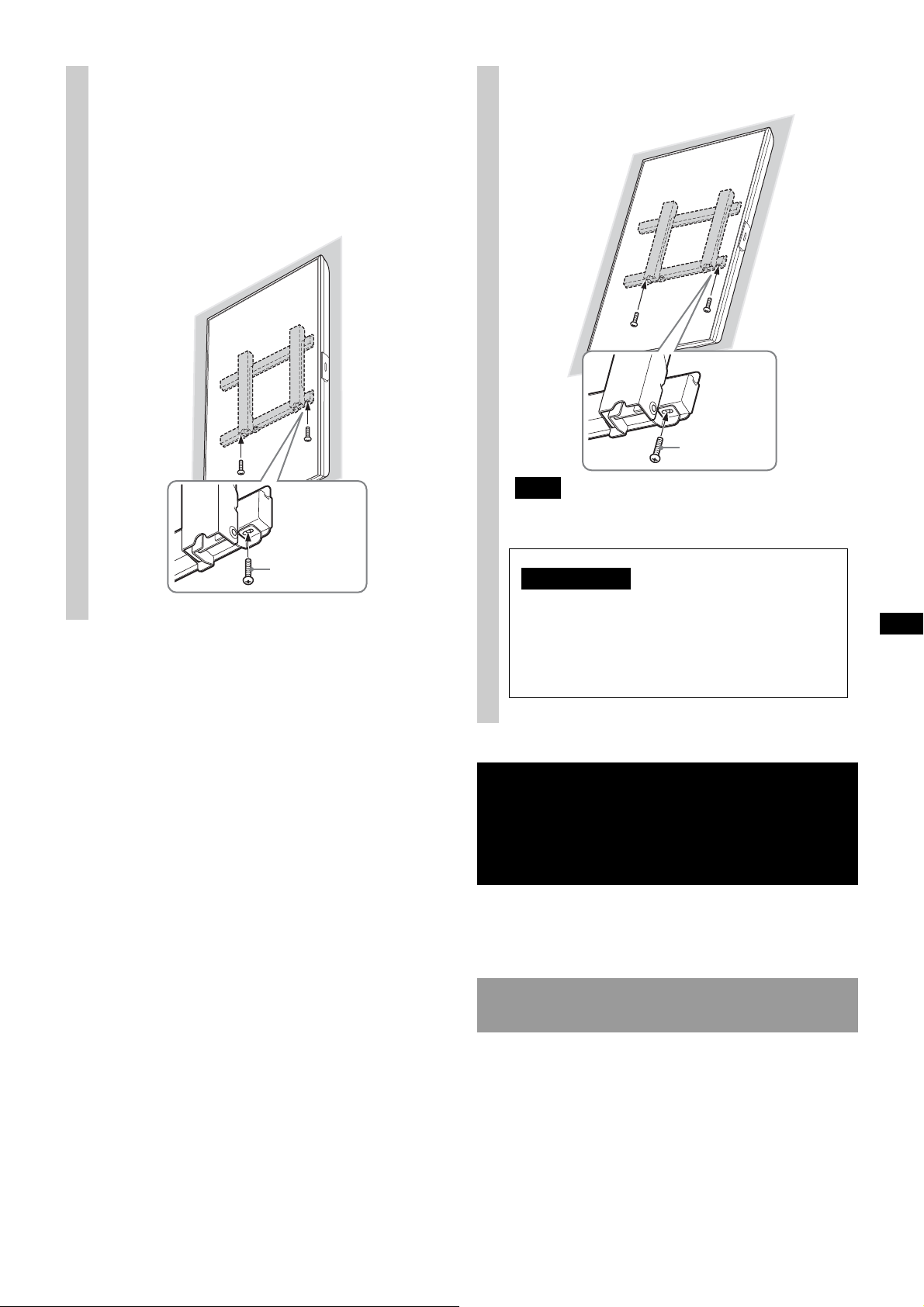
Fije firmemente el televisor y el
Tornillo
(+BVST4 × 12)
Nota
Tornillo
(+BVST4 × 12)
ADVERTENCIA
Asegúrese de apretar firmemente los
tornillos de fijación izquierdo y derecho. De
lo contrario, el televisor podría caerse al
empujarlo hacia arriba y provocar daños
personales.
3
soporte con el tornillo
suministrado junto con el
SU-WL500 (+BVST4 × 12).
C: Vertical, sin inclinación
D: Vertical, inclinación de +20°
Si utiliza un destornillador eléctrico, ajuste el par de
fijación aproximadamente a 1,5 N·m {15 kgf·cm}.
Confirmación de la
finalización de la
instalación
Siga las instrucciones del manual del SU-WL500 para
confirmar.
Para retirar el televisor
Siga las instrucciones del manual del SU-WL500 para
quitarlo.
17 (ES)
Page 58
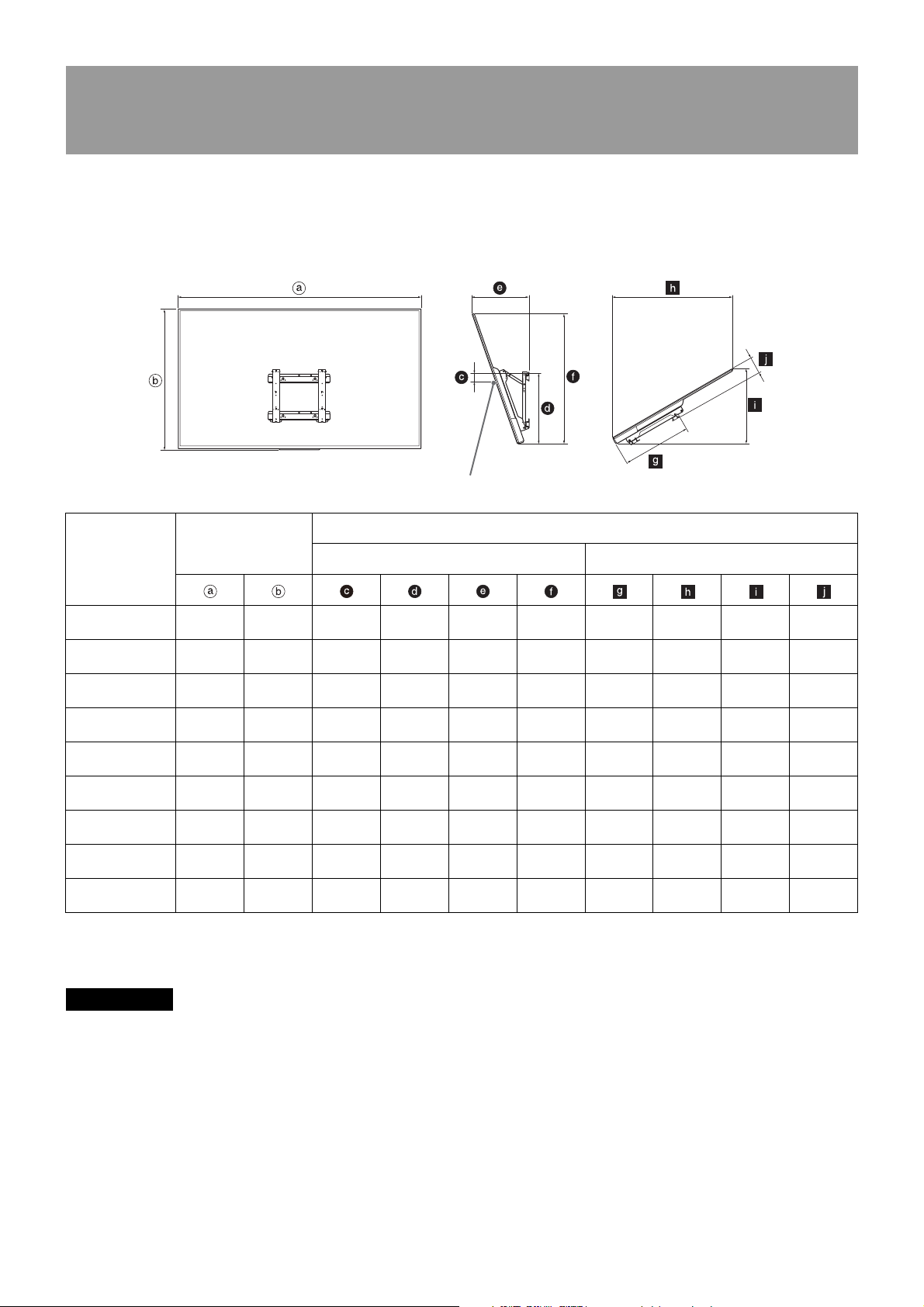
ADVERTENCIA
Tabla de dimensiones para la instalación del
Punto central de la pantalla
televisor
La tabla siguiente muestra las dimensiones del televisor que se monta al producto. Consulte esta tabla para
elegir la ubicación para instalar.
A: Horizontal, inclinación de -20°
B: Horizontal, inclinación de +60°
Unidad: mm (pulgadas)
Longitud de cada ángulo de montaje
410
(16 1/4)
369
(14 5/8)
327
(12 7/8)
297
(11 3/4)
424
(16 3/4)
353
(14)
322
(12 3/4)
330
(13)
315
(12 1/2)
(35 1/2)
(30 3/4)
(26 1/4)
(23 3/8)
(35 7/8)
(31 1/8)
(26 5/8)
(26 5/8)
(23 3/4)
Nombre del
modelo
XBR-75X900E
KD-75X9000E
XBR-65X900E
KD-65X9000E
XBR-55X900E
KD-55X9000E
XBR-49X900E
KD-49X9000E
XBR-75X850E
KD-75X8500E
XBR-65X850E
KD-65X8500E
KD-55X8500E
XBR-55X800E
XBR-49X800E
KD-49X8000E
Dimensiones de
visualización
1.674
(66)
1.447
(57)
1.228
(48 3/8)
1.093
(43 1/8)
1.677
(66 1/8)
1.454
(57 1/4)
1.232
(48 5/8)
1.232
(48 5/8)
1.096
(43 1/4)
(37 7/8)98(3 7/8)
(32 3/4)
(27 7/8)
(24 7/8)
(38 1/8)11(7/16)
(33 1/8)
(28 1/4)
(28 1/4)
(25 1/4)
959
830
707
631
968
840
717
716
640
103
(4 1/8)
161
(6 3/8)
213
(8 1/2)
121
(4 7/8)
187
(7 3/8)
147
(5 7/8)
151
(6)
Ángulo (20º) Ángulo (60º)
549
(21 5/8)
494
(19 1/2)
494
(19 1/2)
511
(20 1/8)
469
(18 1/2)
518
(20 1/2)
527
(20 3/4)
488
(19 1/4)
456
(18)
Es posible que algunos modelos no se encuentren en algunas regiones.
Las figuras en la tabla anterior pueden diferir un poco según la instalación.
901
780
664
592
910
790
674
675
603
————
————
————
————
547
(21 5/8)
1
41
(16 1
/4)
507
(20)
467
(18 1/2)
434
(17 1/8)
840
(33 1/8)
729
(28 3/4)
623
(24 5/8)
623
(24 5/8)
557
(22)
527
(20 3/4)
456
(18)
403
(15 7/8)
406
(16)
369
(14 5/8)
109
(4 3/8)
110
(4 3/8)
123
(4 7/8)
117
(4 5/8)
117
(4 5/8)
La pared sobre la cual se instalará el televisor debe estar en condiciones de soportar al menos cuatro veces el
peso del televisor.
Consulte las instrucciones del televisor para verificar el peso.
18 (ES)
Page 59

C: Vertical, sin inclinación
ADVERTENCIA
Punto central de la pantalla
D: Vertical, inclinación de +20°
Unidad: mm (pulgadas)
Nombre del
modelo
XBR-75X900E
KD-75X9000E
XBR-65X900E
KD-65X9000E
XBR-55X900E
KD-55X9000E
XBR-49X900E
KD-49X9000E
XBR-65X850E
KD-65X8500E
KD-55X8500E
XBR-55X800E
XBR-49X800E
KD-49X8000E
XBR-43X800E
KD-43X8000E
Dimensiones de
visualización
959
(37 7/8)
830
(32 3/4)
707
(27 7/8)
631
(24 7/8)
840
(33 1/8)
717
(28 1/4)
716
(28 1/4)
640
(25 1/4)
565
(22 1/4)
1.674
(66)
1.447
(57)
1.228
(48 3/8)
1.093
(43 1/8)
1.454
(57 1/4)
1.232
(48 5/8)
1.232
(48 5/8)
1.096
(43 1/4)
964
(38)
Dimensiones centrales de la
171
(6 3/4)
121
(4 7/8)
121
(4 7/8)
271
(10 3/4)
121
(4 7/8)
171
(6 3/
221
(8 3/4)
171
(6 3/4)
221
(8 3/4)
pantalla
130
(5 1/8)
69
(2 3/4)
7
(9/32)
102
(4 1/8)
145
(5 3/4)
4)
30
(1 3/16)
70
(2 7/8)
166
(6 5/8)
129
(5 1/8)
354
(14)
351
(13 7/8)
351
(13 7/8)
218
(8 5/8)
281
(11 1/8)
336
(13 1/4)
295
(11 5/8)
161
(6 3/8)
161
(6 3/8)
Es posible que algunos modelos no se encuentren en algunas regiones.
Las figuras en la tabla anterior pueden diferir un poco según la instalación.
Longitud de cada ángulo de montaje
Ángulo (0º) Ángulo (20º)
1.008
(39 3/4)
845
(33 3/8)
735
(29)
818
(32 1/4)
848
(33 1/2)
787
(31)
837
(33)
719
(28 3/8)
703
(27 3/4)
136
(5 3/8)
130
(5 1/8)
130
(5 1/8)
132
(5 1/4)
110
(4 3/8)
123
(4 7/8)
127
(5)
127
(5)
127
(5)
——
——
——
——
518
(20 1/2)
451
(17 7/8)
448
(17 3/4)
409
(16 1/8)
367
(14 1/2)
1.369
(54)
1.162
(45 3/4)
1.162
(45 3/4)
1.034
(40 3/4)
909
(35 7/8)
La pared sobre la cual se instalará el televisor debe estar en condiciones de soportar al menos cuatro veces el
peso del televisor.
Consulte las instrucciones del televisor para verificar el peso.
19 (ES)
Page 60
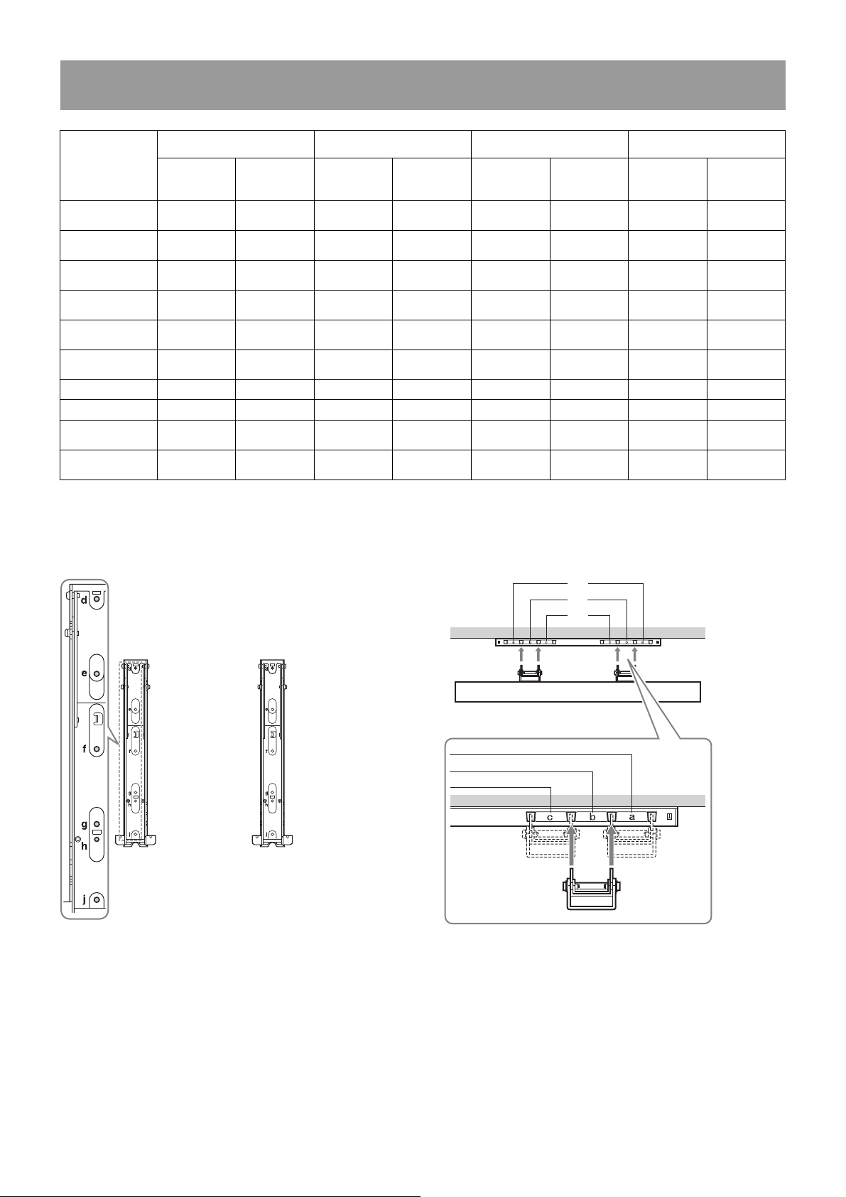
Tabla/diagrama de ubicación de tornillos y gancho
Ubicación de los tornillos
Cuando instale el gancho de soporte al televisor.
Ubicación de los ganchos
Cuando instale el televisor al soporte.
c
a
b
A: Horizontal, inclinación
Nombre del
modelo
XBR-75X900E
KD-75X9000E
XBR-65X900E
KD-65X9000E
XBR-55X900E
KD-55X9000E
XBR-49X900E
KD-49X9000E
XBR-75X850E
KD-75X8500E
XBR-65X850E
KD-65X8500E
KD-55X8500E e, g c e, g c e, g c e, g c
XBR-55X800E e, g b e, g b e, j c e, j c
XBR-49X800E
KD-49X8000E
XBR-43X800E
KD-43X8000E
Ubicación
de -20°
Ubicación
de los
tornillos
d, j a — — d, j a — —
d, g b — — d, g b — —
d, g b — — d, g b — —
f, j c — — f, j c — —
d, gae, ja————
e, j b d, g b d, g b d, g b
f, j c f, j c e, g c e, g c
————f, gcf, gc
de los
ganchos
B: Horizontal, inclinación
Ubicación
de los
tornillos
de +60°
Ubicación
de los
ganchos
C: Vertical, sin inclinación
Ubicación
de los
tornillos
Ubicación
de los
ganchos
D: Vertical, inclinación de
Ubicación
de los
tornillos
+20°
Ubicación
de los
ganchos
20 (ES)
Page 61

http://www.sony.net/
 Loading...