

Page 1
Wall-Mount Bracket
4-100-573-22 (1)
Instructions
Mode d’emploi
Gebrauchsanweisung
Instrucciones
Instructies
Bruksanvisning
Istruzioni
Instruções
Instrukcje
Инcтpyкции
Käyttöohje
Vejledning
GB
FR
DE
ES
NL
SE
IT
PT
PL
RU
FI
DK
Instruksjoner
SU-LW1
© 2003 Sony Corporation
NO
Page 2
Thank you for purchasing this product.
To Customers
Sufficient expertise is required for installing this product. Be sure to subcontract the installation to Sony dealers
or contractors and pay adequate attention to safety during the installation. Sony is not liable for any damages
or injury caused by mishandling or improper installation. Your Statutory Rights (if any) are not affected.
WARNING
If the safety precautions are not observed and the product is used incorrectly, it may result in a fire or serious
injury.
This instruction manual shows the important precautions necessary to prevent accidents and to promote the correct
handling of the product. Be sure to read this instruction manual thoroughly and use the product correctly. Be sure
to keep this instruction manual available for future reference.
For Sony Dealers
Sufficient expertise is required for installing this product. Be sure to read this instruction manual thoroughly to do
the installation work safely. We are not liable for any damage or injury caused by mishandling or improper
installation. Your Statutory Rights (if any) are not affected. Please give this manual to the customer after
installation.
This Wall-Mount Bracket is designed by Sony for use with the specified product. Do not use this bracket with
equipment other than the following products.
Specified products: LCD Colour TV (KDL-L32MRX1/KLV-L32MRX1/KLV-30MR1/KLV-26HG2/KLV-L32M1)
On Safety
Products by Sony are designed with safety in mind.
If the products are used incorrectly, however, it may result in a serious injury through fire, electric shock, the
product toppling over, or the product dropping. Be sure to observe the precautions for safety to prevent such
accidents.
2 (GB)
Page 3
For Customers
WARNING
If the following precautions are not observed, there is a possibility of either death or serious injury
through a fire, an electric shock or an explosion.
Be sure to subcontract the installation to qualified contractors and keep small
children away during the installation.
If persons other than qualified contractors install the Wall-Mount Bracket,
the following accidents may happen.
• The Display Unit may fall and cause a serious injury such as a bruise or a
fracture during an earthquake.
• If the wall on which the Wall-Mount Bracket is installed is unstable,
uneven, or not perpendicular to the floor, the unit may fall and cause
injury or property damage. The wall should be capable of supporting a
weight of at least four (4) times the Display Unit weight (KDLL32MRX1/KLV-L32MRX1: 23 kg × 4 = 92 kg, KLV-30MR1: 20 kg × 4 =
80 kg, KLV-26HG2: 15 kg × 4 = 60 kg, KLV-L32M1: 17 kg × 4 = 68 kg).
• If the installation of the Wall-Mount Bracket on the wall is not
sufficiently sturdy, the unit may fall and cause injury or property
damage.
Be sure to subcontract the installation to qualified contractors when moving
or dismounting the Wall-Mount Bracket.
If persons other than qualified contractors transport or dismount the Wall-Mount Bracket, the Display Unit may
fall and cause injury or property damage. Be sure that two or more persons carry or dismount the Wall-Mount
Bracket.
Do not spill liquid of any kind on the Display Unit.
If you allow the Display Unit to get wet, this may result in a fire or an electric shock.
Do not remove bolts, etc., after mounting the Display Unit.
If you do so, the Display Unit may fall.
Do not disassemble or make alterations to the parts of the Wall-Mount
Bracket.
If you do so, the Wall-Mount Bracket may fall and cause injury or property
damage.
GB
English
Do not mount any equipment other than the specified product.
This Wall-Mount Bracket is designed for use with the specified product. If you mount equipment other than the
specified product, it may fall and cause injury or property damage.
3 (GB)
Page 4
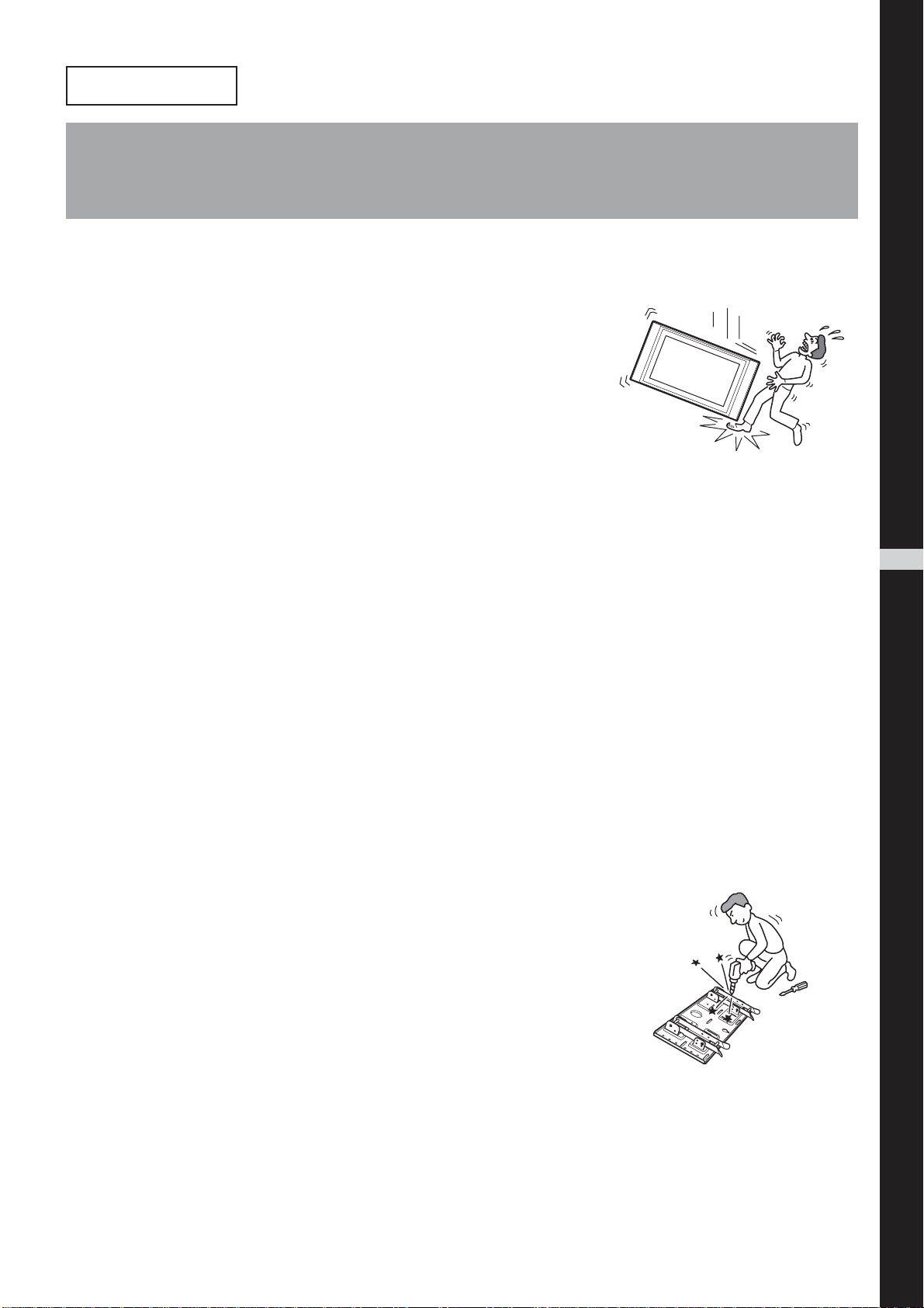
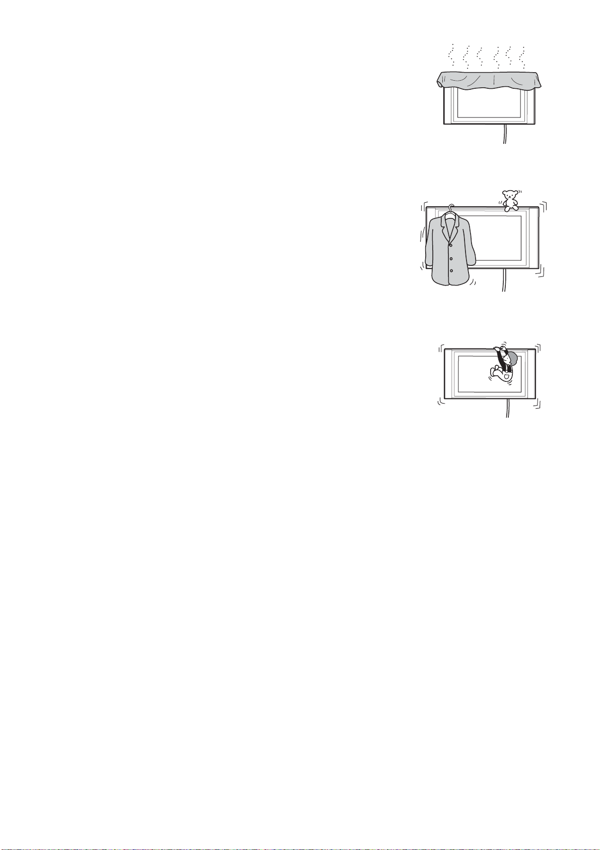
Do not block the ventilating holes on the Display Unit.
If you block the ventilating holes on the Display Unit by covering the top of
the Display Unit with a cloth or the like, the Display Unit may become
overheated and this may cause a fire.
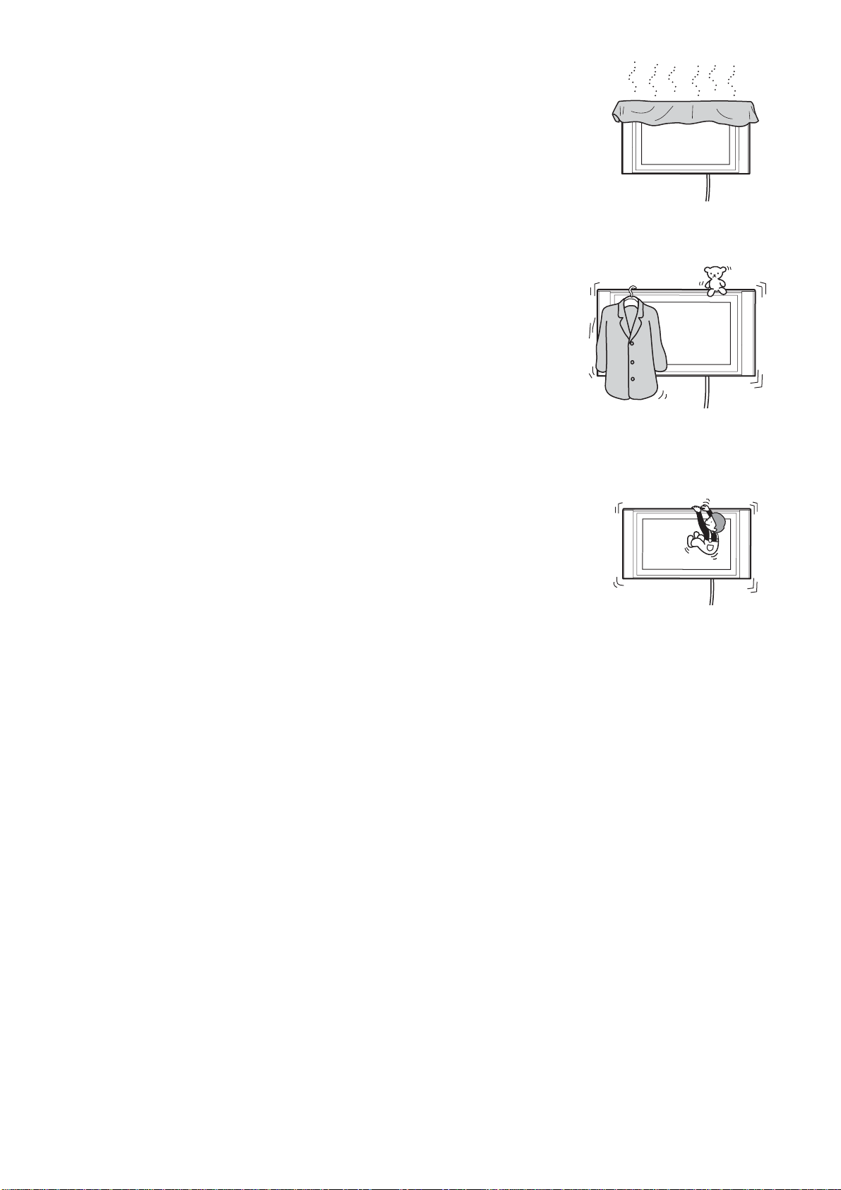
Do not apply any load other than the Display Unit on the Wall-Mount
Bracket.
If you do so, the Display Unit may fall and cause injury or property
damage.
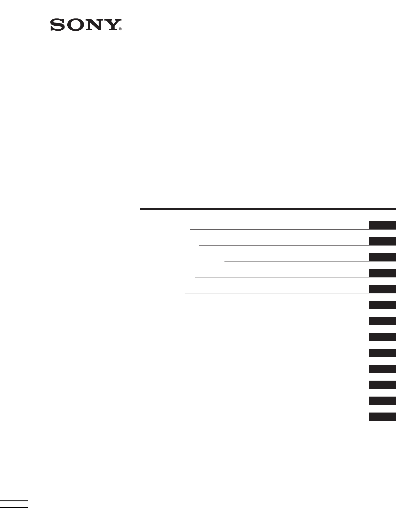
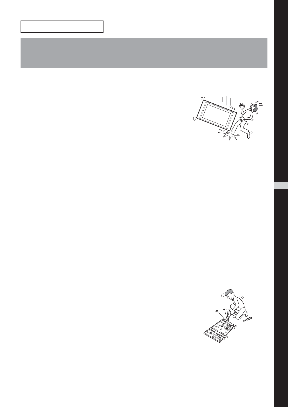
Do not lean on or hang from the Display Unit.
The Display Unit may fall and the user may be caught under the weight of
the unit and suffer serious injury.
To prevent a fire or an electric shock, do not expose the Display Unit to rain
or moisture.
If you allow the Display Unit to get wet, this may result in a fire or an electric shock.
Never place the Display Unit in hot, humid or excessively dusty places. Do not
install the Display Unit where it may be exposed to mechanical vibrations.
If you do so, this may cause a fire or an electric shock.
Keep flammable objects or open flames (e.g. candles) away from the Display
Unit.
To prevent a fire, keep flammable objects or open flames (e.g. candles) away from the Display Unit.
4 (GB)
Page 5
CAUTION
If the following precautions are not observed, there is a possibility of injury or property damage.
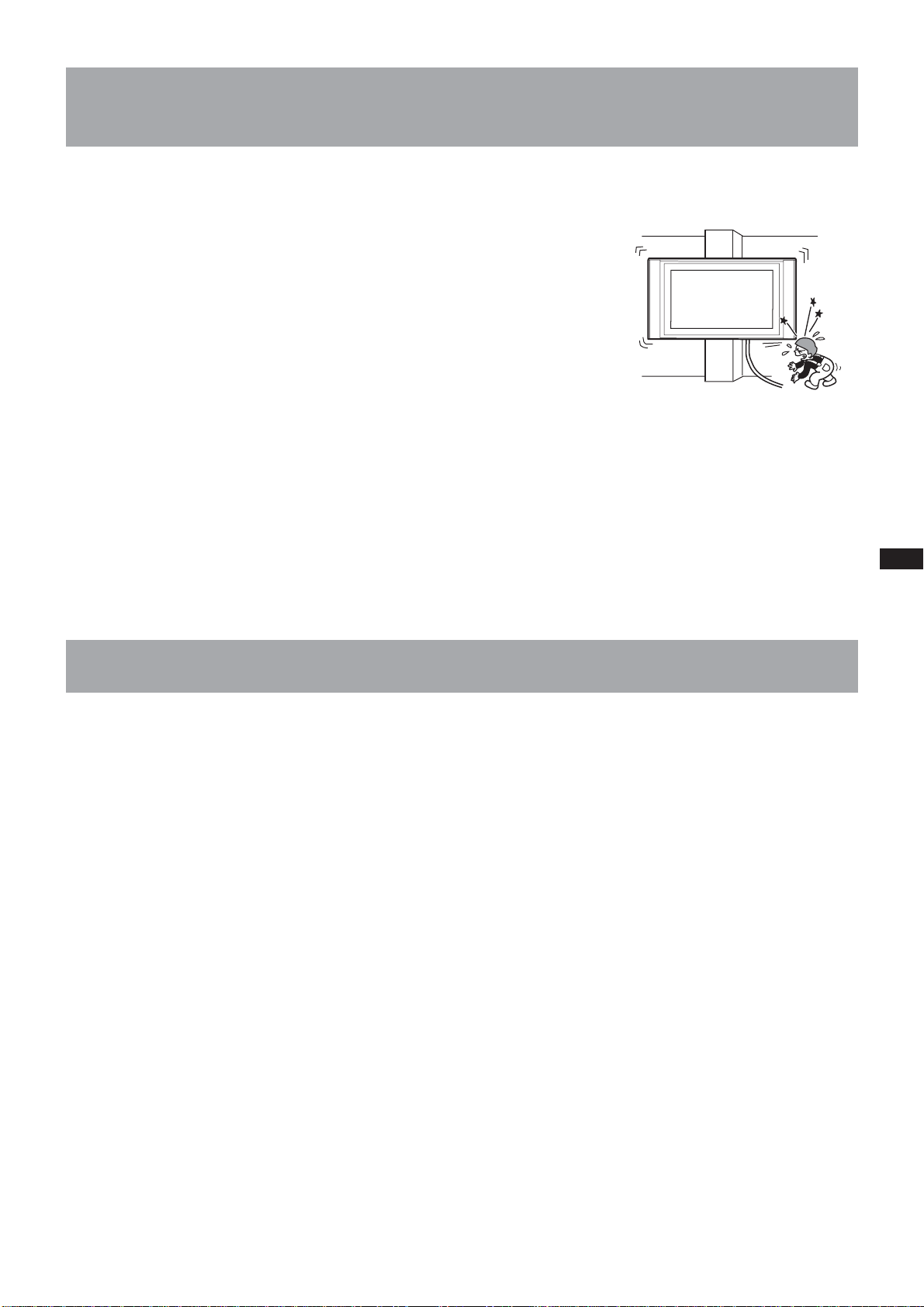
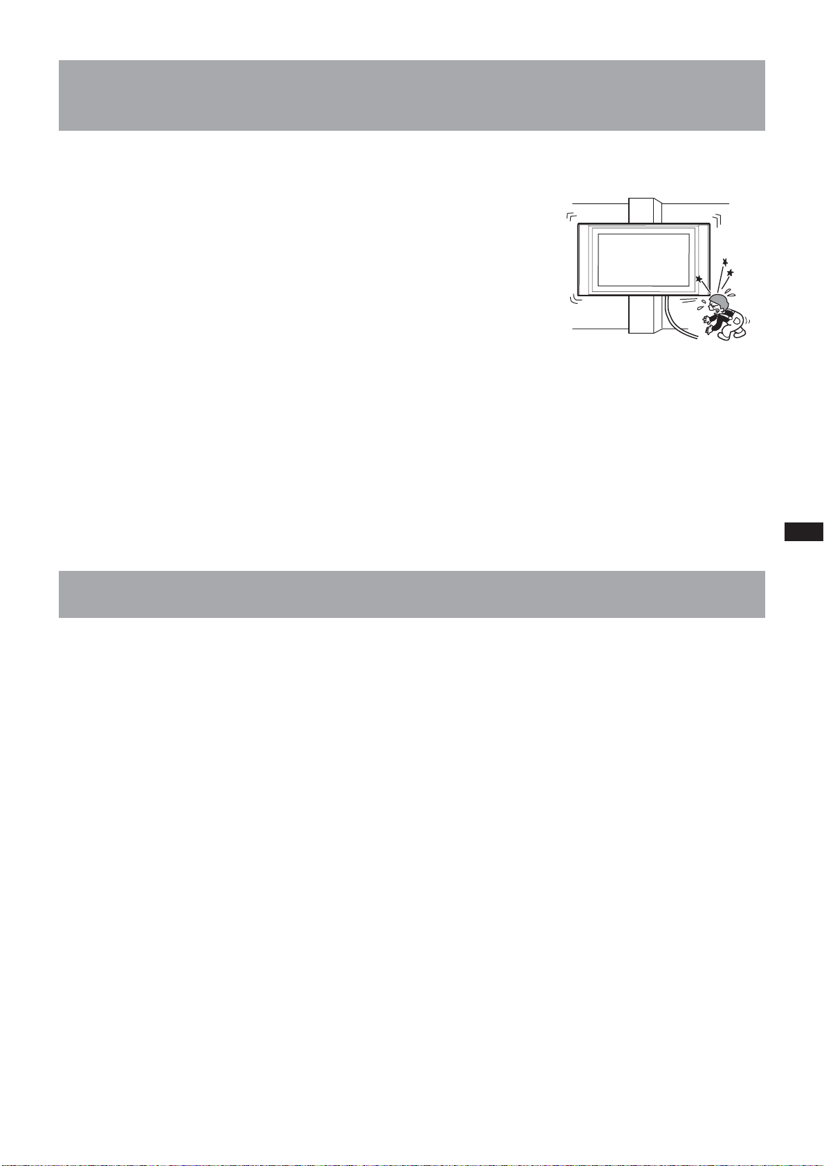
Do not install the Wall-Mount Bracket on wall surfaces where the corners or
the sides of Display Unit would protrude away from the wall surface.
Do not install the Wall-Mount Bracket on wall surfaces such as a pillar,
where the corners or the sides of Display Unit would protrude away from
the wall surface. If a person or object happens to hit the protruded corner
or side of the Display Unit, this may cause injury or property damage.
Do not handle the product with excessive force during cleaning or
maintenance.
Do not apply excessive force on the topside of the Display Unit.
If you do so, this may cause injury or property damage by causing the Display Unit to fall.
Do not install the Display Unit over or under an air-conditioner.
If you do so, the Display Unit may be exposed to air currents from the air-conditioner. This may result in a
malfunction of the Display Unit.
Precautions
• If you use the Display Unit installed on the Wall-Mount Bracket for a long time, the wall behind or above the
Display Unit may become discolored or the wallpaper may come unstuck, depending on the material of the wall.
If the Wall-Mount Bracket is removed after installing them on the wall, the screw holes are left.
• If you have routed 300 ohm feeder cables behind the wall, we recommend that you change them to 75 ohm
coaxial cables.
If it is necessary to continue to use 300 ohm feeder cables, be sure to confirm that sufficient space is available
between the Display Unit and the feeder cables behind the wall before starting the installation.
Consult your contractor on an appropriate installation location where the Display Unit suffers no radio noise
before starting the installation.
5 (GB)
Page 6
Install the Wall-Mount Bracket
For Sony Dealers
WARNING To Customers
Sufficient expertise is required for installing this product. Be sure to subcontract the installation to Sony dealers
or contractors and pay adequate attention to safety during the installation.
To Sony Dealers
The following instructions are for Sony Dealers only. Be sure to read the following safety precautions and pay
adequate attention to safety during the installation, maintenance and checking of this product.
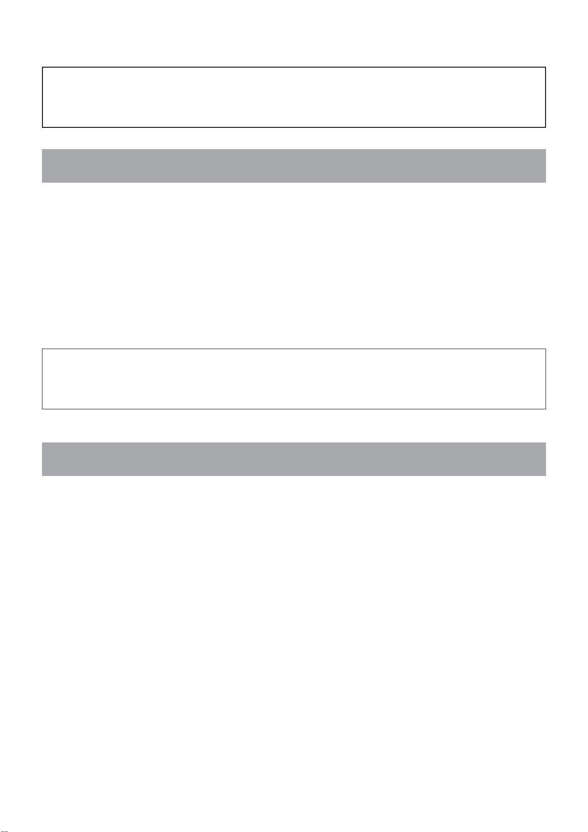
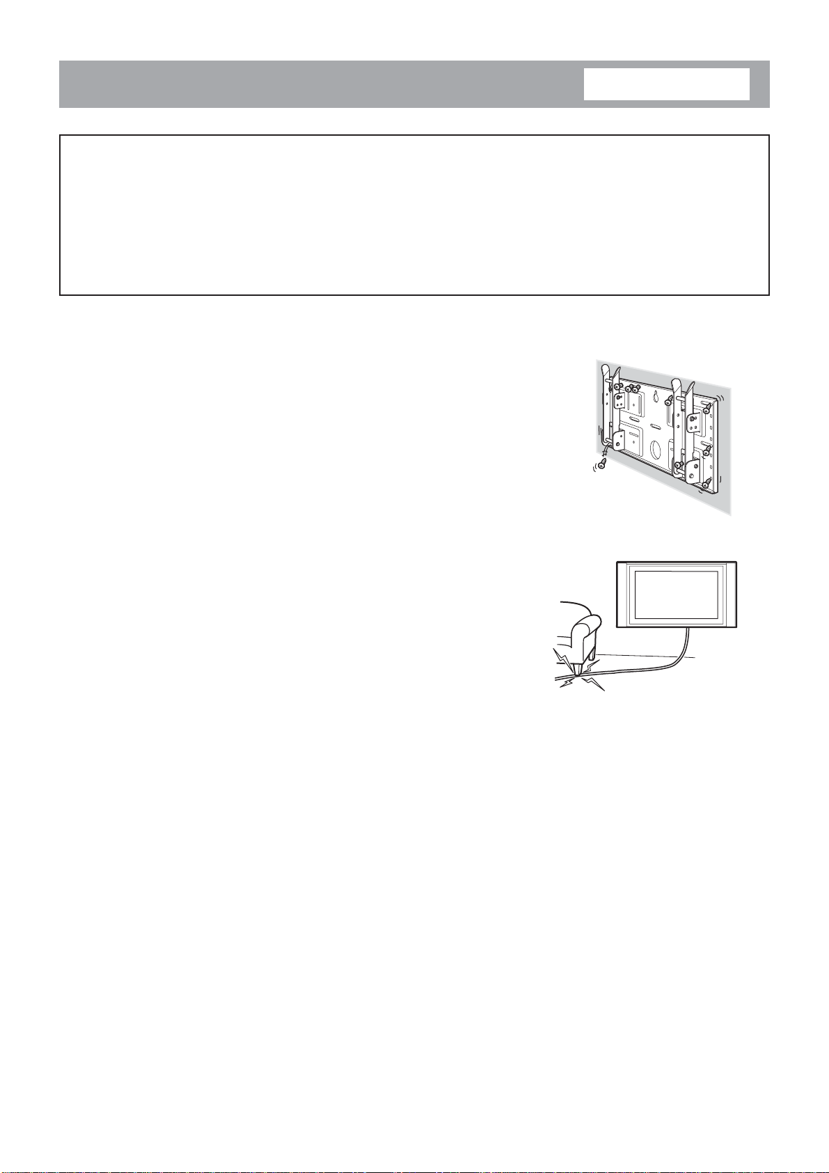
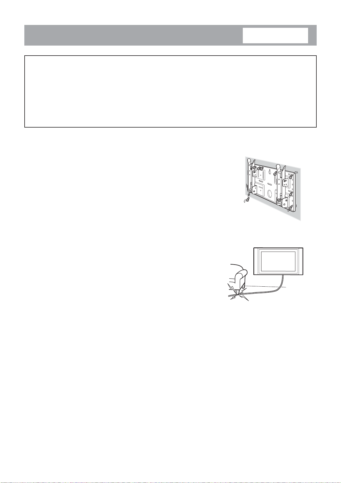
Be sure to install the Wall-Mount Bracket securely to the wall following the
instructions in this instruction manual.
If any of the screws are loose or fall out, the Wall-Mount Bracket may fall
and cause injury or property damage. Be sure to use the screws appropriate
for the material of the wall and install the unit securely, using five or more
M6 or the equivalent screws.
Do not allow the Power Cord or the Display Cable to be pinched.
If the Power Cord or the Display Cable is pinched between the unit and the
wall or is bent or twisted by force, the metallic part of the cord or cable may
be exposed and cause a short circuit or a break in the cord or cable. This
may cause a fire or an electric shock.
Be sure to use the supplied screws and attachment parts properly following
the instructions given in this instruction manual. If you use substitute items,
the Display Unit may fall, and cause bodily injury to someone or damage to
the Display Unit.
Be sure to assemble the bracket properly following the instructed procedure
explained in this instruction manual.
If any of the screws are loose or fall out, the Display Unit may fall, and cause bodily injury to someone or damage
to the Display Unit.
Be sure to tighten the bolts and screws securely in the designated position.
If you fail to do so, the Display Unit may fall, and cause bodily injury to someone or damage to the Display Unit.
Be careful not to subject the Display Unit to shock during installation.
If the Display Unit is exposed to shock, it may fall or break apart. This may cause injury.
6 (GB)
Page 7
Be sure to install the Display Unit on a wall that is both perpendicular and
flat.
If you fail to do so, the Display Unit may fall and cause injury.
After proper installation of the Display Unit, secure the cables properly.
If people or objects get tangled in the cables, this may result in injury.
Be careful not to hurt your hands or fingers during the installation.
Be careful not to hurt your hands or fingers when installing the Wall-Mount Bracket or the Display Unit.
The screws needed to secure the Wall-Mount Bracket to the wall are not
supplied.
Use the appropriate screws for the wall material and structure when mounting the Wall-Mount Bracket.
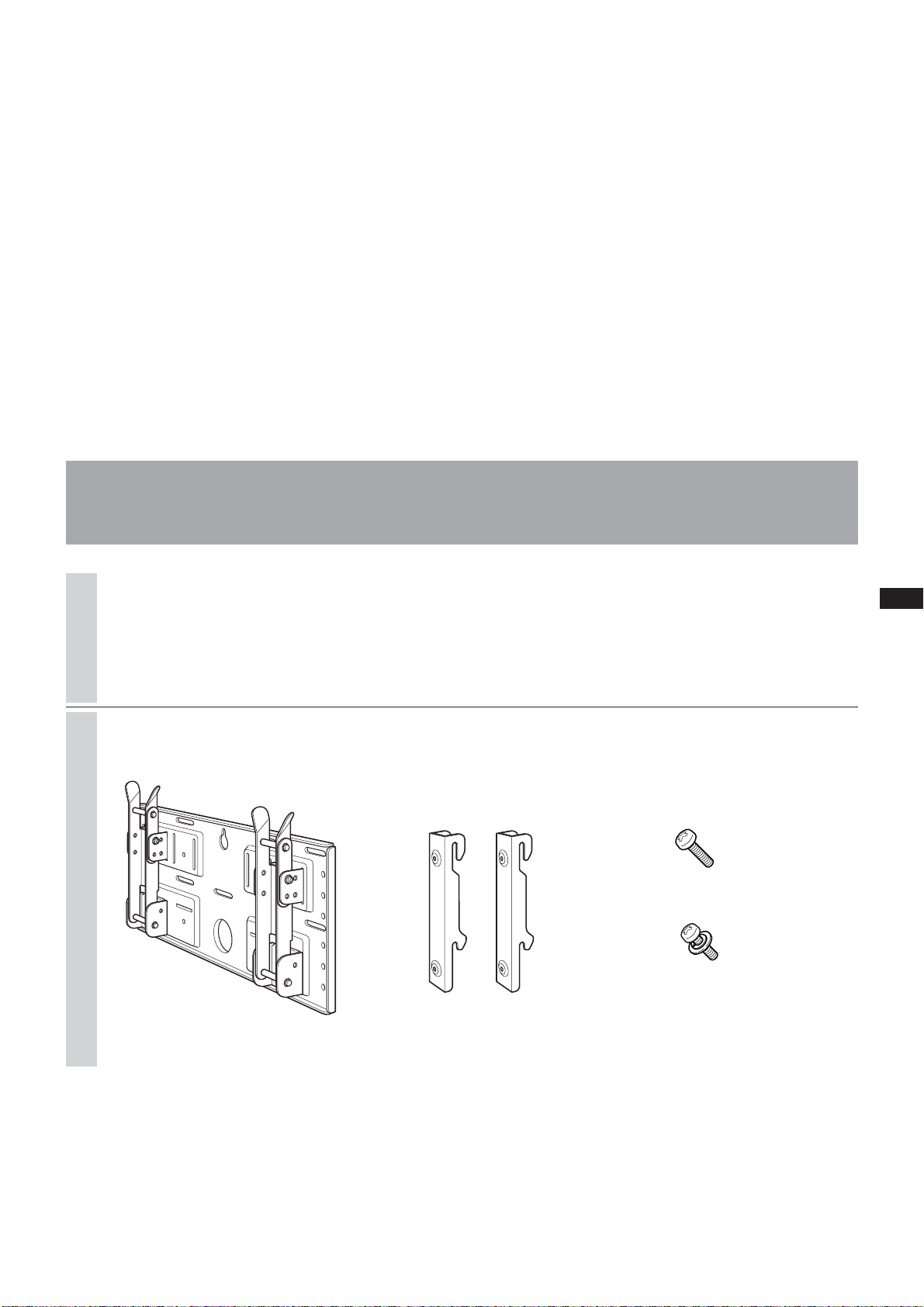
Step 1: Check to see that you have all the items
necessary for installation
1
2
Prepare five or more M6 or
equivalent screws (not supplied) and
a screwdriver. Select screws suitable
for the material of the wall.
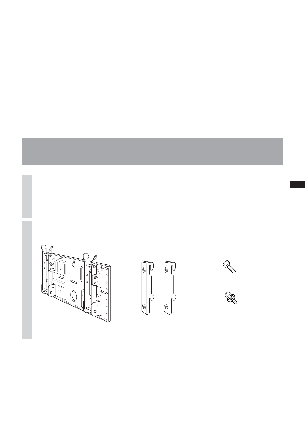
Unpack the carton and check to see
that all the following items are
included.
Screws (+B5 × L12) (2)
Screws (+PSW5 × L16) (4)
(For the KLV-26HG2)
Plate Unit (1) Mounting Hook Unit (2)
7 (GB)
Page 8
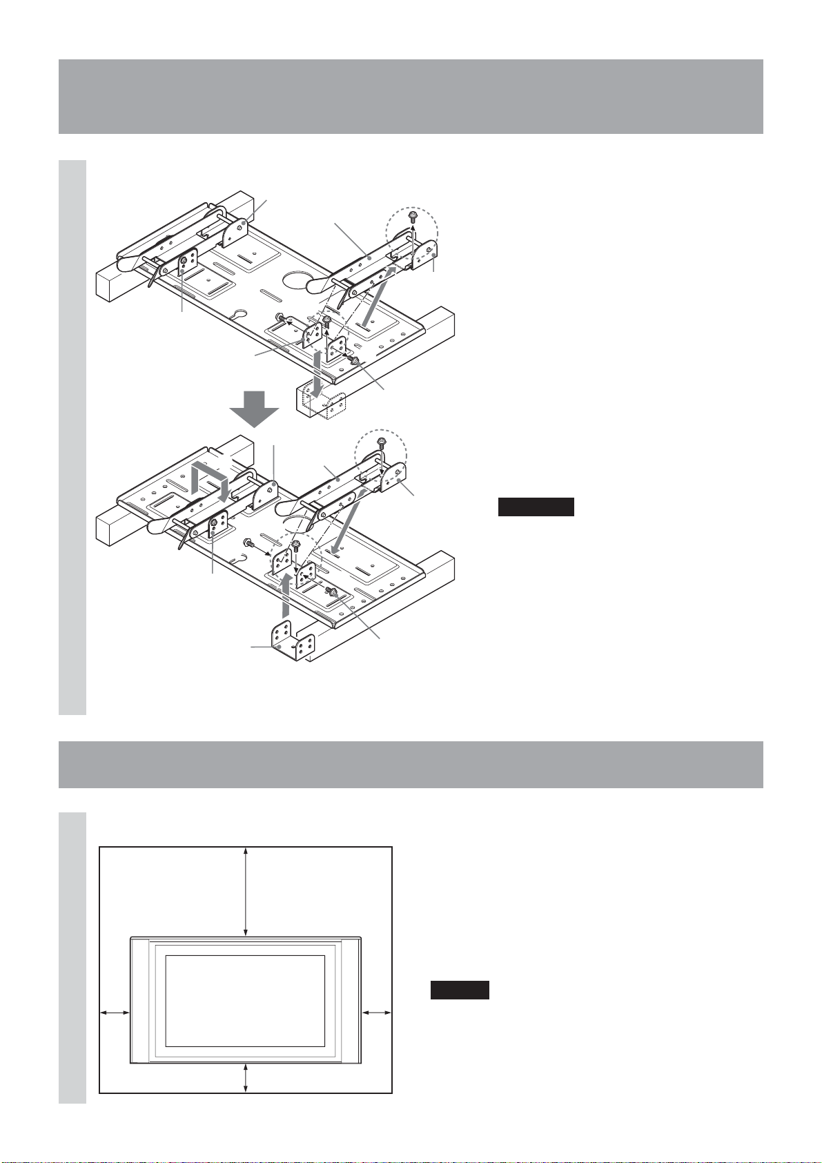
Step 2: Adjust the position of the arm bases
(For the KLV-26HG2 and the KLV-L32M1 only)
If you are going to install a KDL-L32MRX1,
1
Arm base A
Arm base A
Arm base A
3
5
Arm base B
1
Arm base B
2
Arm
4
Arm
2
Arm base B
1
Tilt adjuster
4
Arm base B
3
5
a KLV-L32MRX1 or a KLV-30MR1, skip
Step 2 and go to Step 3.
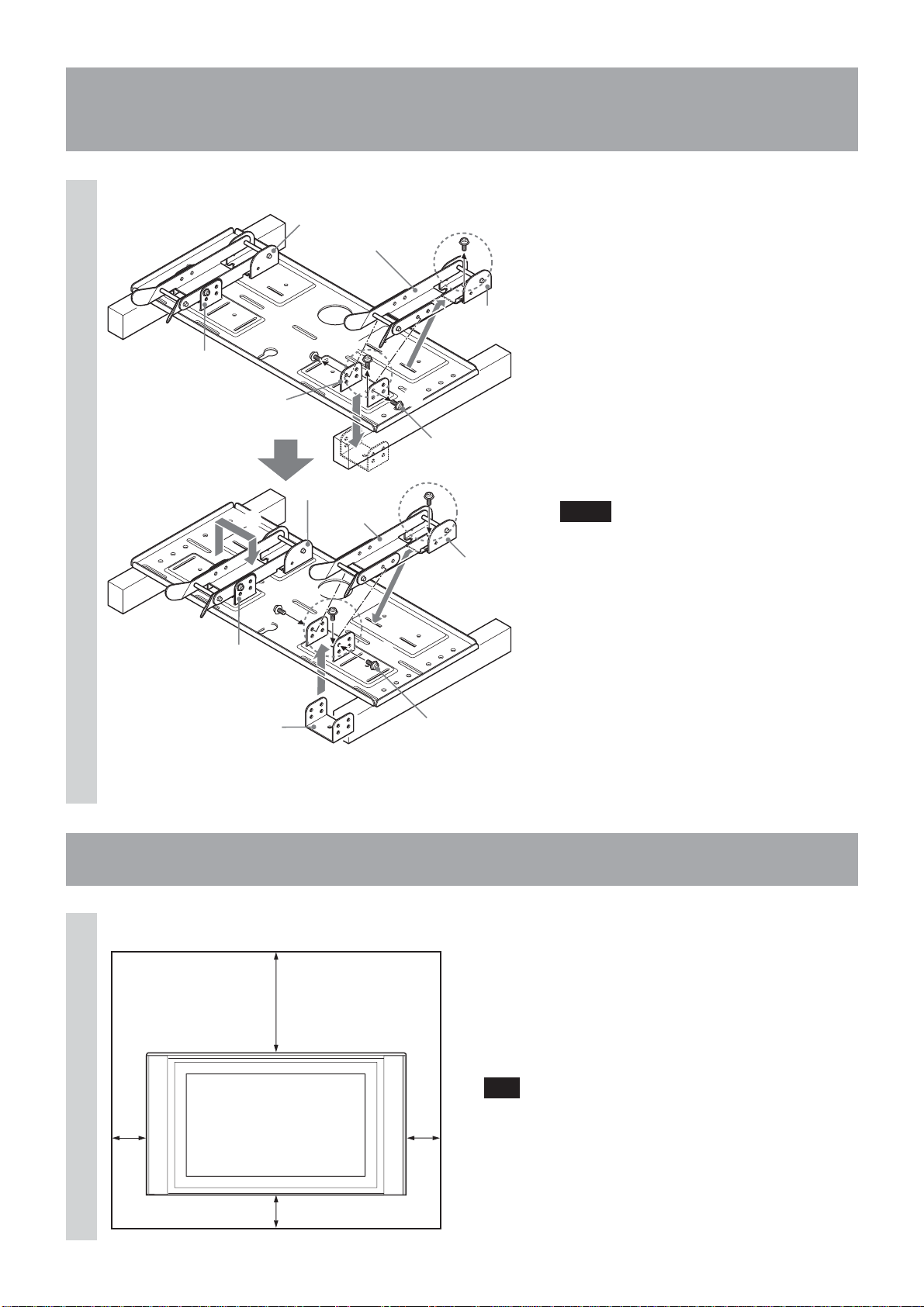
1Remove the four (two for each arm
bases) tilt adjusters .
2Remove the four screws that secure the
arm bases to the Plate Unit.
3Remove the arm bases A and put them
in the slots facing inward. Put both arms
and the arm bases B on the arm bases
A.
4Secure the arm bases to the Plate Unit
using the four screws removed in 2.
5Secure the arms to the arm bases using
the four tilt adjusters removed in 1.
Notes
• If you are installing a display other than
the KLV-26HG2 or the KLV-L32M1, skip
Step 2.
•When using an electric screwdriver to
tighten the screws, the torque must be
approx. 2 N•m.
3
Arm base A
Tilt adjuster
Step 3: Decide on the location for installation
1
Unit: mm
100
300
100
Leave spaces around the display. At
least the amount of space shown in
the diagram should be left between
the display and a ceiling or raised
portions of the wall.
Tip
Refer to the table (9 (GB)) for the display installation
dimensions.
8 (GB)
100
Page 9
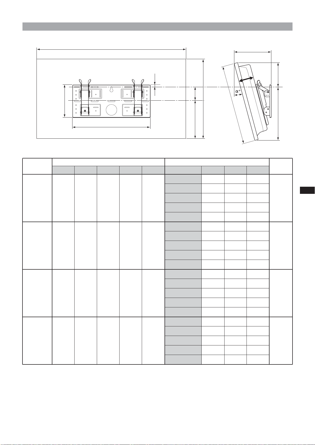
Display installation dimensions table
A
14
F
C
D
210
B
B
E
500
Display
Model
KLV-30MR1 971 524 93 68 268 10° 206 167 352
A BCDE
Display Dimensions
Unit: mm
Length for each mounting angle
Mounting angle (α°)
0° 147 188 336
5° 177 179 345
15° 234 152 258
FGH (×4)*
Unit: mm
G
H
Weight
20 kg
(80 kg)
20° 260 135 363
0° 151 247 322
5° 186 237 331
KDL-L32MRX1
1,052 569 97 31 291 10° 219 225 339
KLV-L32MRX1
15° 252 209 345
20° 282 190 350
0° 167 150 280
5° 194 139 291
KLV-26HG2 790 430 118 65 215 10° 220 129 301
15° 244 122 310
20° 266 113 318
0° 165 281 323
5° 198 273 333
KLV-L32M1 835 604 111 -5 328 10° 230 262 342
15° 262 248 349
20° 292 231 356
23 kg
(92 kg)
15 kg
(60 kg)
17 kg
(68 kg)
* The wall must be strong enough to support at least four times the weight of the display that you are installing.
9 (GB)
Page 10
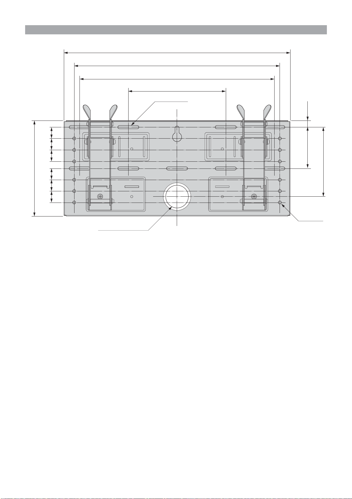
Wall installation diagram
252525
210
252525
Unit: mm
500
454
430
215
9-7×40
Oblong hole
91 14
148
12-φ7
φ60
Hole for cable routing
Refer to the diagram above for wall installation requirements (when reinforcing the wall or routing cables in the
wall).
WARNING
The wall must be strong enough to support at least four times the weight of the display that you are installing
(9 (GB)). Make sure the wall has sufficient strength. Reinforce the wall if necessary.
10 (GB)
Page 11
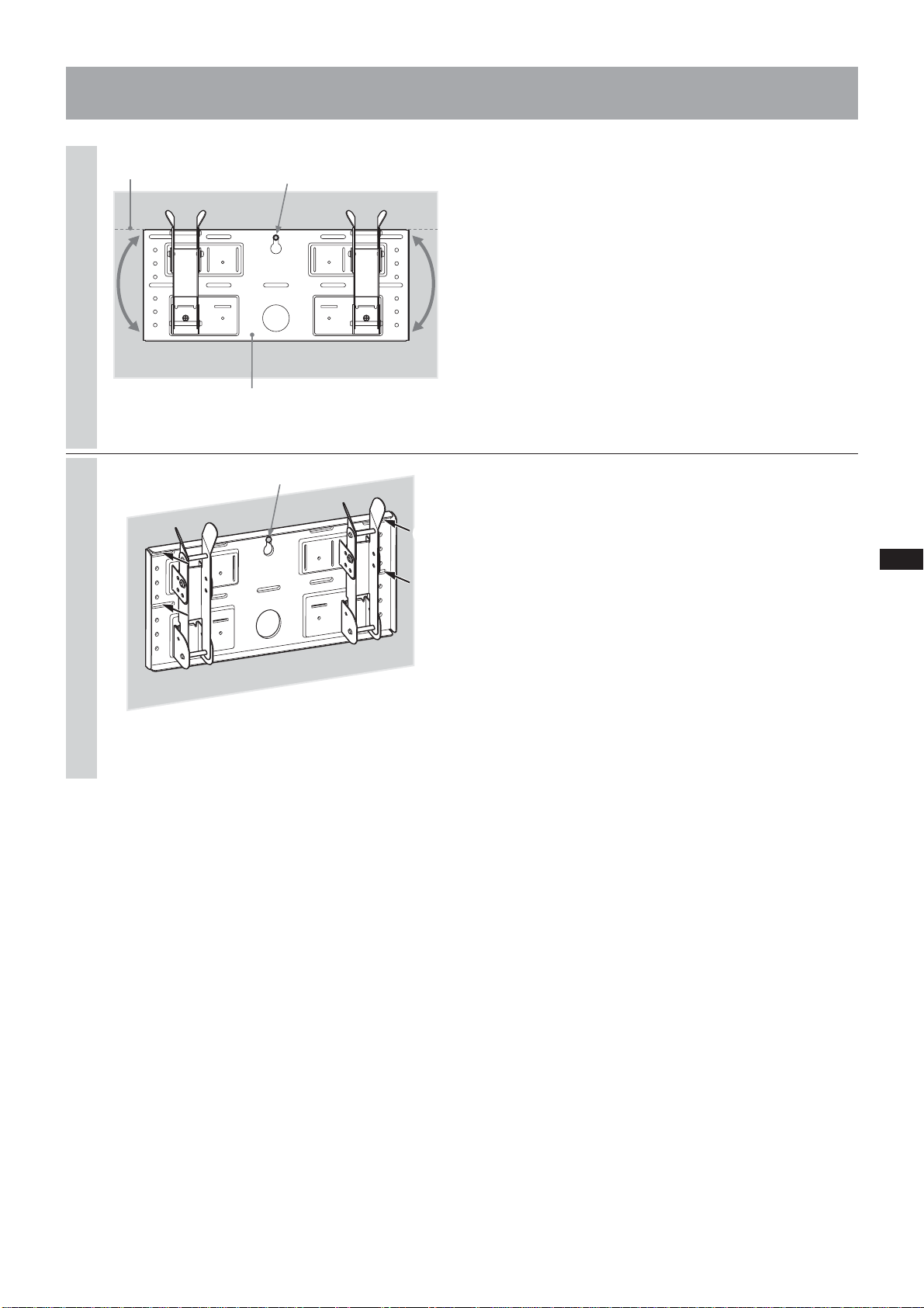
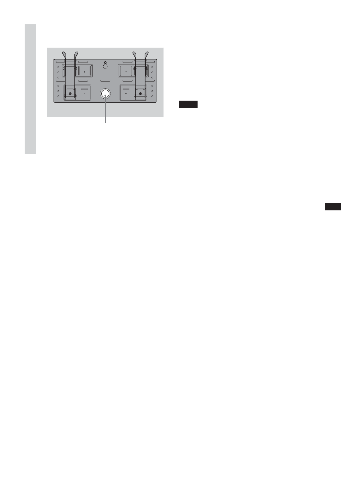
Step 4: Install the Plate Unit on the wall
Align the Plate Unit.
1
2
Hole used for temporarily
attaching the Plate Unit
Plate Unit
2
1
Temporarily secure the Plate Unit to
the wall using a screw. Align the
Plate Unit to make it level with the
floor.
WARNING
• The screw used in this procedure is not supplied
with the unit.
• Select a screw suitable for the material and the
structure of the wall.
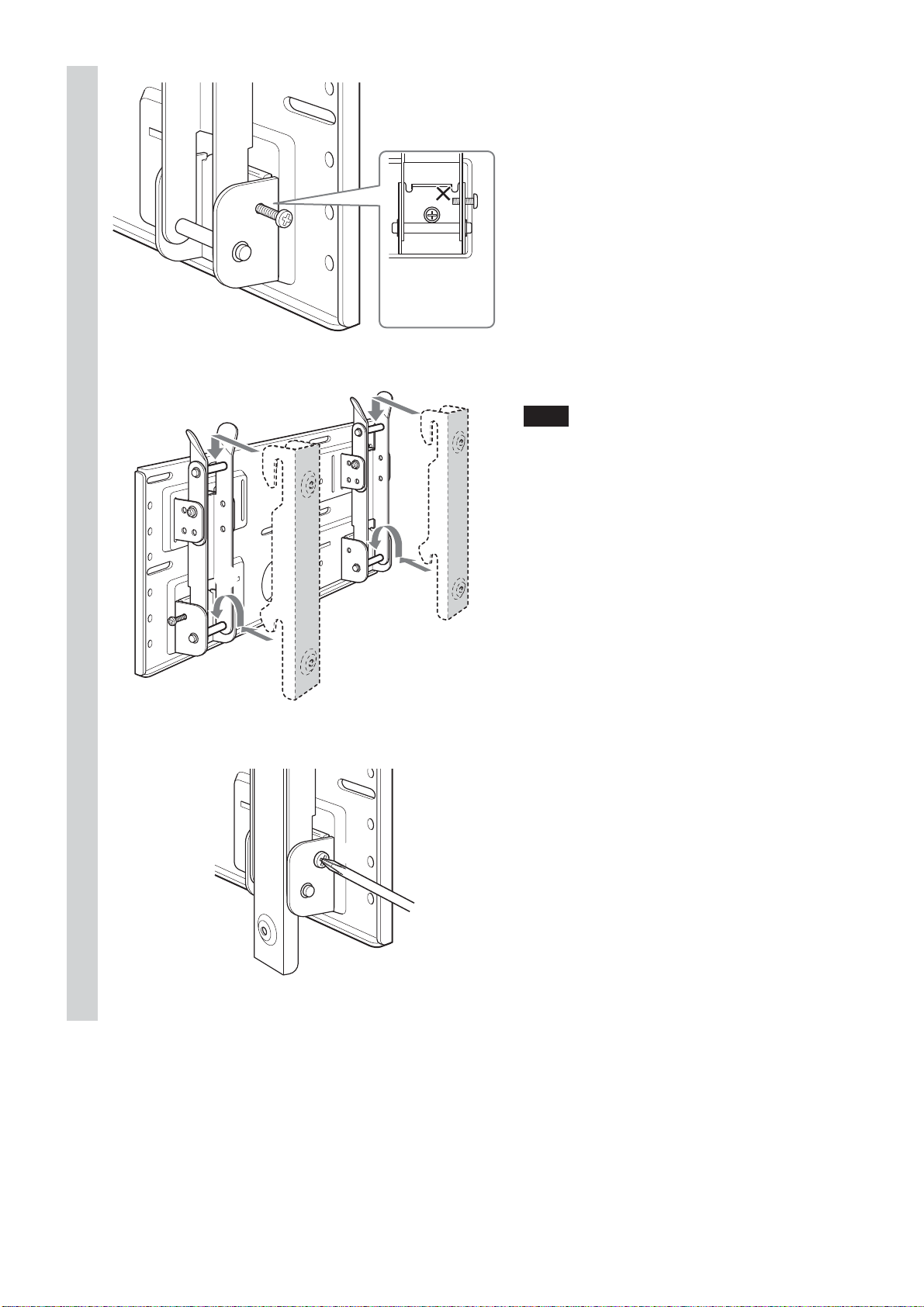
Secure the Plate Unit to the wall
using four or more M6 or equivalent
screws (not supplied).
1Tighten the screws firmly so that the Plate Unit can
support the weight of the display.
2Tighten the screw used in 1.
WARNING
The wall must be strong enough to support at least
four times the weight of the display that you installing
(9 (GB)). Make sure the wall has sufficient strength.
Reinforce the wall if necessary.
11 (GB)
Page 12
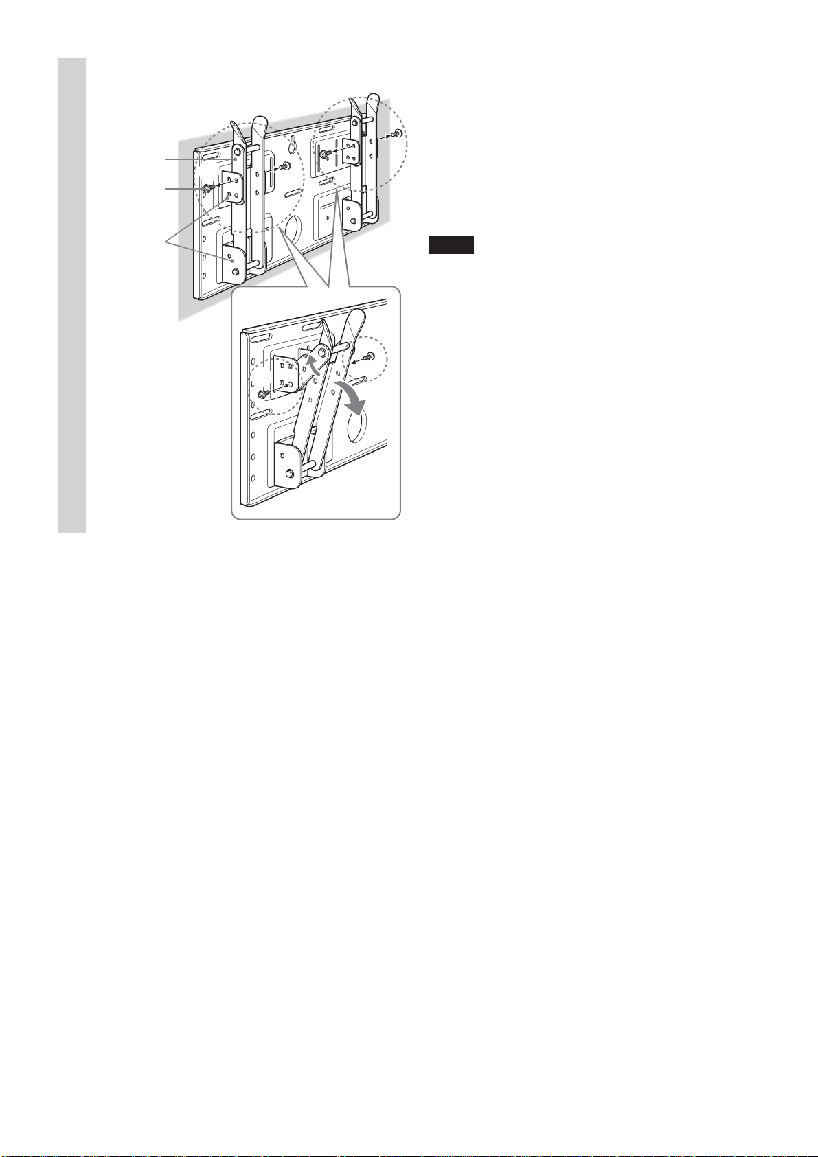
3
Adjust the tilt of the arms.
If you want to install the display vertically, flush with
the wall (0°), skip 1 and 2 below. Check that the
arms are securely attached to the Plate Unit.
Arm
Tilt adjuster
Arm bases
A and B
1
2
1Remove all four tilt adjusters.
2Put them into the screw holes corresponding to the
desired angle (5°, 10°, 15°, or 20°) and tighten them
firmly.
Notes
• The angle of the left and right arms must be the
same.
• Be careful not to catch your fingers when adjusting
the angle of the arms.
•When using an electric screwdriver to tighten the
screws, the torque must be approx. 2 N•m.
• Check that the arm bases are securely attached to
the Plate Unit.
12 (GB)
Page 13
Step 5: Detach the display from the Tabletop Stand
The procedure differs depending on the display model. Apply the procedure
appropriate for the display you are installing.
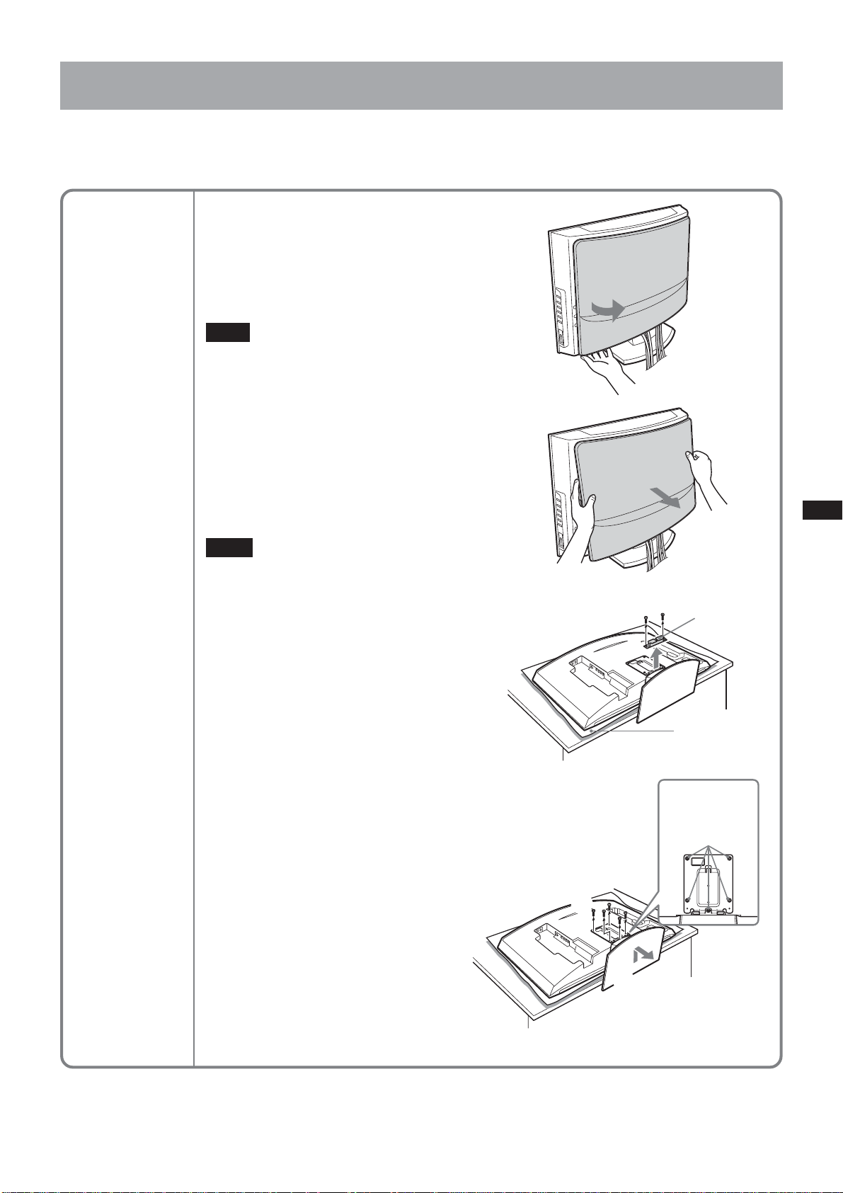
KLV-26HG2
1Pull the lower corner (either right or
left ) of the rear cover. Then pull the
other lower corner.
2Hold the rear cover with both hands
and pull it towards you. The rear
cover will separate from the display.
Note
Lay the display face down on a soft cloth
before going to 3.
3Remove the two small screws from
the clip. Detach the clip from the
Tabletop Stand.
4Remove the five screws from the
Tabletop Stand.
5Lift up the Stand slightly, then pull it
towards you. The Stand will separate
from the display.
Notes
• Lay the display face down on a stable
and level surface, leaving the base of
the Stand sticking out in the air.
Putting the display face and the base
of the Stand on the same level surface
makes the Display Unit inclined, thus
unstable, causing any danger.
•When removing the Tabletop Stand,
hold it firmly.
1
2
3
Clip
Soft cloth
4
5
Screws
removed in 4
13 (GB)
Page 14
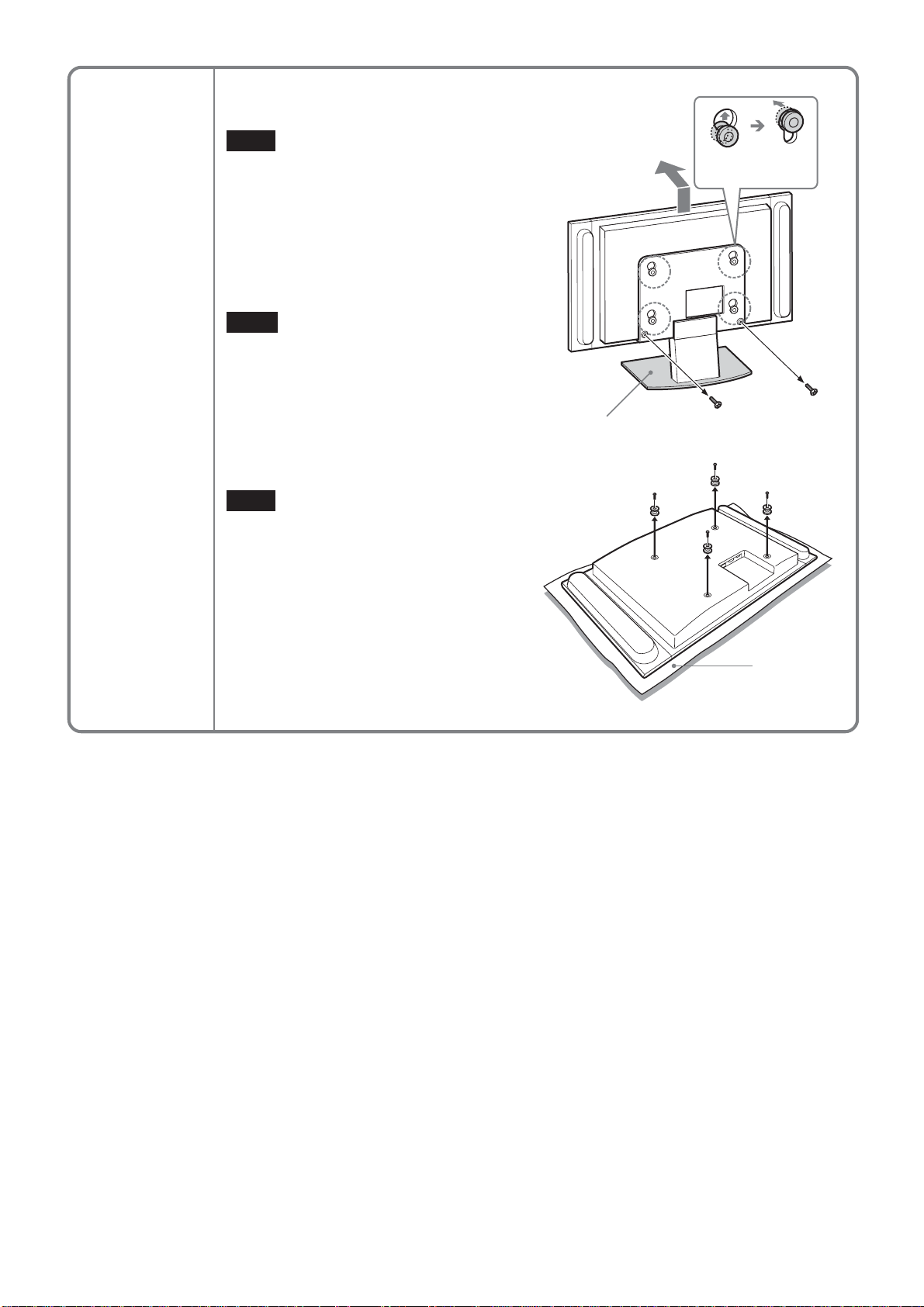
KLV-30MR1
1Remove the two screws from the Tabletop
Stand.
Note
Do not lay the display down when carrying
out the procedure.
2Holding down the base of the Stand, lift
up the display slightly, then move it away
from the Stand. The display will separate
from the Stand. At least two persons must
hold and carry the display.
Notes
• At least two persons must work together
on this procedure.
•When lifting up the display, hold the base
of the Stand so that it is not lifted along
with the display.
3Remove the four hooks on the rear cover
of the display.
Lift up and carry
forward.
2
1
Base of the Stand
Note
Lay the display face down on a soft cloth.
3
Soft cloth
14 (GB)
Page 15
KDL-L32MRX1
KLV-L32MRX1
1Remove the two screws from the Tabletop
Stand.
Note
Do not lay the display down when carrying
out the procedure.
2Holding down the base of the Stand, lift
up the display slightly, then move it away
from the Stand. The display will separate
from the Stand. At least two persons must
hold and carry the display.
Notes
• At least two persons must work together
on this procedure.
•When lifting up the display, hold the base
of the Stand so that it is not lifted along
with the display.
3Remove the two hooks on the rear cover
of the display.
Lift up and carry
forward.
2
1
Base of the Stand
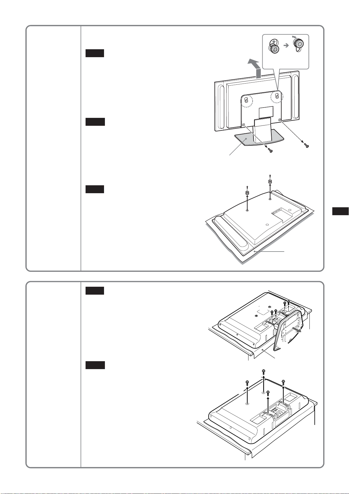
KLV-L32M1
Note
Lay the display face down on a soft cloth.
Note
Lay the display face down on a soft cloth
before going to 1.
1Remove the four screws from the rear
cover of the display.
2Pull the stand towards you. The Stand
will separate from the display.
3Remove the four screws on the rear
cover of the display.
Notes
• Lay the display face down on a stable
and level surface, leaving the base of
the Stand sticking out in the air.
Putting the display face and the base
of the Stand on the same level surface
makes the Display Unit inclined, thus
unstable, causing any danger.
•When removing the Tabletop Stand,
hold it firmly.
3
Soft cloth
1
2
Soft cloth
3
15 (GB)
Page 16
Step 6: Install the display on the Plate Unit
WARNING
Do not connect the power cord to a wall socket before the installation is completed. If the mains lead is
pinched, a short circuit may occur, causing an electric shock.
Be careful not to stumble over the cables or the display.
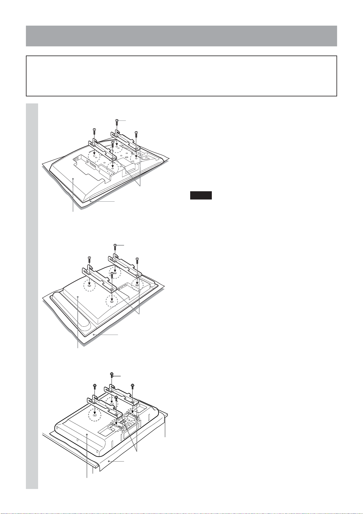
KLV-26HG2
1
Rear of the display
The supplied screws
(+PSW5 × L16)
Mounting Hook Units
Soft cloth
KDL-L32MRX1/KLV-L32MRX1/KLV-30MR1
The screws removed
in Step 5
Align the holes on the Mounting
Hook Units with the corresponding
holes on the rear of the display.
Secure them to the display using
four screws.
For the KLV-26HG2, use the screws supplied (+PSW5
× L16). For the KDL-L32MRX1, the KLV-L32MRX1,
the KLV-30MR1, and the KLV-L32M1 use the screws
you removed in Step 5.
Notes
• Lay the display face down on a soft cloth.
•When using an electric screwdriver to tighten the
screws, the torque must be approx. 2 N•m.
16 (GB)
Mounting Hook Units
Soft cloth
Rear of the display
KLV-L32M1
The screws removed
in Step 5
Mounting Hook Units
Soft cloth
Rear of the display
Page 17
2
Hole for cable routing
Connect the supplied mains lead
and cables.
Connect the mains lead and cables to the
corresponding jacks on the rear of the display. For
details on the cable connection, see the Operating
Instructions for your display.
When routing cables in a wall, pass the cables through
a hole made in the wall for cable routing (10 (GB)).
Notes
•You cannot connect the cables to the display after
installing it on the Plate Unit.
• Subcontract the cable routing in the wall to
qualified contractors.
17 (GB)
Page 18
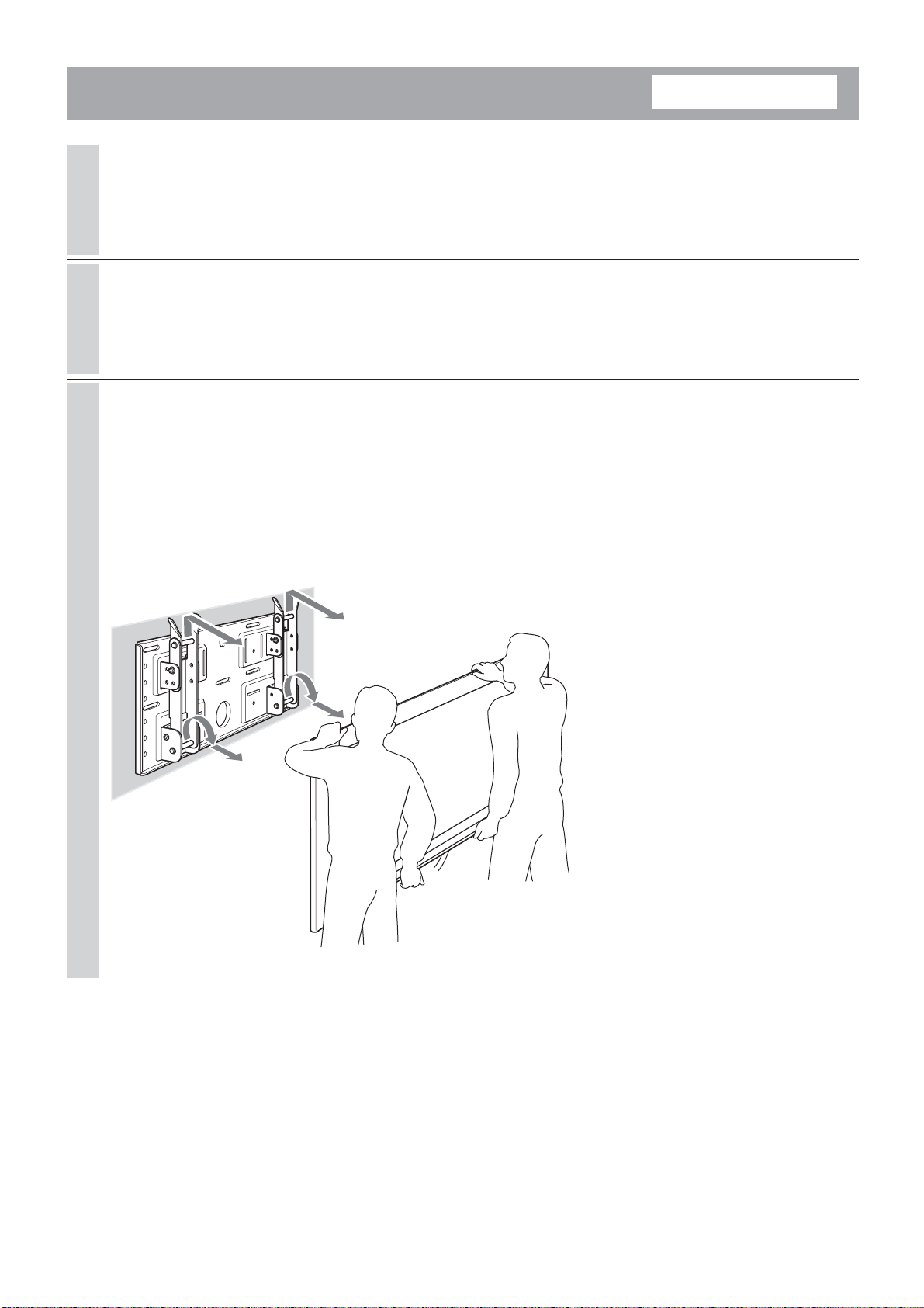
3
1
Do not push
the screws in
too far.
Mount the display on the Plate
Unit.
1To lock the arms temporarily, put the two
securing screws (+B5 × L12, supplied) in the
holes on the arm bases B from the outside.
2Hang the upper hooks of the Mounting Hook
Units on the upper shafts of the arms.
3Place the lower hooks of the Mounting Hook
Units on the lower shafts of the arms.
4Pushing the display towards the Plate Unit,
lift it up slowly and hang the lower hooks of
the arms onto the lower shafts.
5Check to make sure that all eight hooks are
properly hung on the corresponding shafts.
6Tighten the securing screws attached in 1.
2
Note
If you push the securing screws into the holes
too far (1), the tips of the screws will get in the
way when you hang the lower hooks on the
shafts (4).
4
3
6
18 (GB)
Page 19
Check to make sure all the procedures have been
properly completed
Check the following.
• All eight hooks are securely hung on the corresponding shafts.
• The cables are neither twisted nor pinched.
• The two securing screws are securely tightened.
WARNING
If not properly installed, the unit may fall, causing injury to persons or damage to the unit itself. If the cables
are not properly routed, a short circuit may occur, causing a fire or an electric shock. For your safety, be sure to
check that all the procedures have been properly carried out.
19 (GB)
Page 20
To dismount the display
1
2
3
For Sony Dealers
Unplug the mains lead from the wall
socket.
Remove the two securing screws.
Two or more persons should lift up
the display and dismount it from the
Plate Unit.
WARNING
• At least two persons must hold and carry the
display.
•When dismounting the display, be careful not to
catch the cables.
•When dismounting the display, be careful of your
hands and fingers.
20 (GB)
Page 21
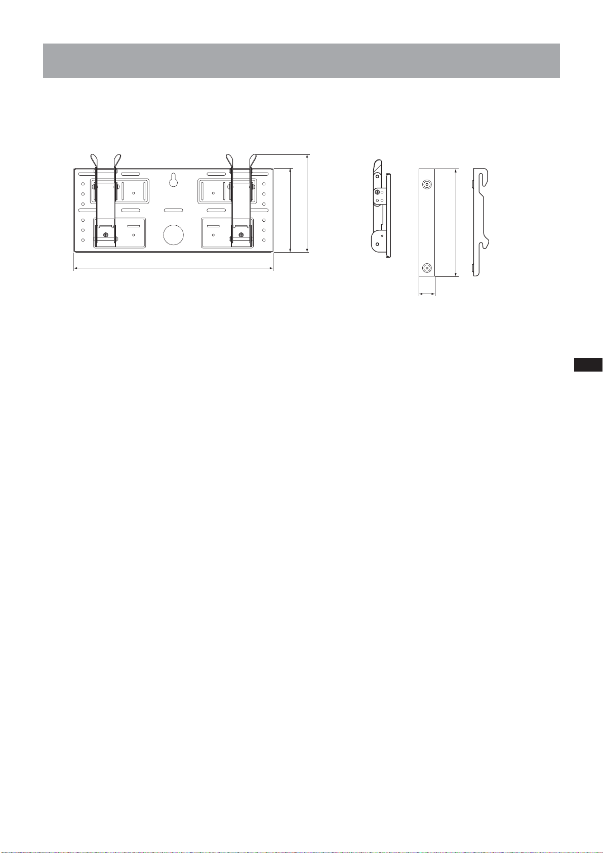
Specifications
Unit: mm
Mass: 3.4 kg
500
210
245
270
40
Design and specifications are subject to change without notice.
21 (GB)
Page 22
Nous vous remercions d’avoir fait l’acquisition de ce produit.
A l’attention des clients
Une certaine expérience est requise pour installer ce produit. Confiez l’installation à des revendeurs Sony ou à
des professionnels et portez une attention particulière à la sécurité au cours de l’installation. Sony ne peut être
tenu pour responsable de quelque dommage ou blessure que ce soit consécutif(ve) à une mauvaise utilisation
ou à une installation incorrecte. Vos droits prévus par la loi (le cas échéant) ne sont pas affectés.
AVERTISSEMENT
Le non-respect des règles de sécurité et l’utilisation incorrecte de ce produit peut provoquer un incendie ou des
blessures graves.
Ce mode d’emploi indique les précautions essentielles pour éviter tout accident et garantir une bonne utilisation
du produit. Lisez attentivement ce mode d’emploi et veillez à utiliser ce produit correctement. Conservez ce mode
d’emploi pour toute référence ultérieure.
A l’attention des revendeurs Sony
Une certaine expérience est requise pour installer ce produit. Lisez ce mode d’emploi attentivement afin de
procéder à l’installation en toute sécurité. Nous ne sommes nullement responsables de tout dommage ou blessure
consécutif(ve) à une mauvaise utilisation ou à une installation incorrecte. Vos droits prévus par la loi (le cas
échéant) ne sont pas affectés. Une fois l’installation terminée, remettez ce manuel d’installation aux clients.
Ce support de fixation mural est conçu par Sony pour être utilisé avec le produit spécifié. N’utilisez pas ce
support avec un autre appareil que le produit suivant.
Produits spécifiés : LCD Colour TV (KDL-L32MRX1/KLV-L32MRX1/KLV-30MR1/KLV-26HG2/KLV-L32M1)
Sécurité
Les produits Sony sont conçus pour vous offrir le maximum de sécurité.
Toutefois si les produits sont utilisés de façon incorrecte, ils peuvent provoquer des blessures graves en cas
d’incendie, d’électrocution, de chute ou s’ils basculent de leur support. Veillez à observer les consignes de sécurité
préconisées pour éviter de tels accidents.
2 (FR)
Page 23
A l’attention des clients
AVERTISSEMENT
Le non-respect des précautions suivantes peut entraîner la mort ou des blessures graves en cas
d’incendie, d’électrocution ou d’explosion.
Confiez l’installation à des professionnels qualifiés et tenez les enfants à
l’écart pendant la durée de l’installation.
Si des personnes autres que des professionnels qualifiés installent le
support de fixation mural, les accidents suivants peuvent se produire :
•L’écran peut tomber et causer des blessures graves comme des
hématomes ou des fractures en cas de tremblement de terre.
• Si le mur sur lequel le support de fixation mural est fixé est instable,
inégal ou non perpendiculaire au sol, l’appareil risque de tomber et de
vous blesser ou de provoquer des dommages matériels. Le mur doit
pouvoir supporter un poids équivalent à quatre (4) fois le poids de
l’écran (KDL-L32MRX1/KLV-L32MRX1 : 23 kg × 4 = 92 kg,
KLV-30MR1 : 20 kg × 4 = 80 kg, KLV-26HG2 : 15 kg × 4 = 60 kg,
KLV-L32M1 : 17 kg × 4 = 68 kg).
• Si l’installation du support de fixation mural n’est pas assez solide,
l’appareil risque de tomber et de vous blesser ou de provoquer des
dommages matériels.
Confiez l’installation à des professionnels qualifiés lorsque vous déplacez ou
démontez le support de fixation mural.
Si des personnes autres que des professionnels qualifiés transportent ou démontent le support de fixation mural,
l’écran peut tomber et provoquer des blessures ou des dommages matériels. Deux personnes au moins doivent
porter ou démonter le support de fixation mural.
Ne renversez aucun liquide sur l’écran.
Si ce dernier venait à être mouillé, il risquerait de provoquer un incendie ou une électrocution.
Ne retirez pas de boulons, etc., après l’installation de l’écran.
Dans le cas contraire, l’écran risque de tomber.
Ne démontez pas ou n’apportez pas de modifications aux pièces du support
de fixation mural.
Dans le cas contraire, le support risque de tomber et de vous blesser ou de
provoquer des dommages matériels.
FR
Français
N’utilisez pas d’autre appareil que le produit spécifié.
Ce support de fixation mural est conçu pour être utilisé avec le produit spécifié. Si vous installez un autre appareil
que le produit spécifié, il risque de tomber et de vous blesser ou de provoquer des dommages matériels.
3 (FR)
Page 24
Ne bloquez pas les orifices de ventilation de l’écran.
Si vous bloquez les orifices de ventilation de l’écran en couvrant la partie
supérieure de l’écran avec un tissu ou autre, l’écran peut surchauffer et ceci
risque de provoquer un incendie.
N’appliquez aucune charge autre que l’écran sur le support de fixation mural.
Dans le cas contraire, l’écran risque de tomber et de vous blesser ou de
provoquer des dommages matériels.
Ne vous appuyez pas sur l’écran ou ne vous pendez pas après.
L’écran risquerait de tomber et l’utilisateur serait coincé par le poids de
l’appareil, il en résulterait des blessures graves.
Pour éviter tout risque d’incendie ou d’électrocution, n’exposez pas l’écran à
la pluie ou à l’humidité.
Si l’écran venait à être mouillé, il risquerait de déclencher un incendie ou une électrocution.
Ne placez jamais l’écran dans des endroits chauds, humides ou extrêmement
poussiéreux. N’installez pas l’écran à des endroits où il serait soumis à des
vibrations mécaniques.
Dans le cas contraire, ceci risque de provoquer un incendie ou un risque d’électrocution.
Conservez les objets inflammables ou les flammes nues (ex : bougies) à l’écart
de l’écran.
Pour éviter tout risque d’incendie, gardez les objets inflammables ou les flammes nues (ex : bougies) à l’écart de
l’écran.
4 (FR)
Page 25
ATTENTION
Le non-respect des précautions suivantes risque de provoquer des blessures ou des dommages matériels.
N’installez pas le support de fixation mural sur des surfaces murales où les
coins ou les côtés de l’écran dépasseraient.
N’installez pas le support de fixation mural sur des surfaces murales, telles
qu’un pilier où les coins ou les côtés de l’écran dépasseraient de la surface.
Si une personne ou un objet venait à heurter le coin ou les côtés de l’écran,
ceci risquerait de provoquer une blessure ou d’endommager appareil.
N’exercez aucune force excessive sur le produit en cours de nettoyage ou
d’entretien.
N’exercez pas une force excessive sur la face supérieure de l’écran.
Dans le cas contraire, l’écran risque de tomber et de vous blesser ou entraîner des dommages matériels.
N’installez pas l’écran sur ou sous un climatiseur.
Dans le cas contraire, l’écran risque d’être exposé aux courants d’air du climatiseur. Ceci risquerait de provoquer
un dysfonctionnement de l’écran.
Précautions
• Si vous utilisez l’écran fixé au support de fixation mural pendant une longue période, le mur situé derrière ou
au-dessus de l’écran peut se décolorer ou le papier peut se décoller selon le matériau du mur. Les trous des vis
restent apparents si vous démontez le support de fixation mural après son installation.
• Si vous avez fait passer des câbles d’alimentation de 300 ohms derrière le mur, nous vous recommandons de les
remplacer par des câbles coaxiaux de 75 ohms.
Toutefois, s’il est nécessaire de continuer à utiliser des câbles d’alimentation de 300 ohms, un espace
suffisamment important doit être prévu entre l’écran et les câbles d’alimentation derrière le mur avant de
procéder à l’installation.
Avant de procéder à l’installation, consultez votre installateur sur l’emplacement où l’écran ne subira aucune
interférence radio.
5 (FR)
Page 26
Installation du support de fixation mural
revendeurs Sony
AVERTISSEMENT A l’attention des clients
A l’attention des
Une certaine expérience est requise pour installer ce produit. Confiez l’installation à des revendeurs Sony ou à
des professionnels et portez une attention particulière à la sécurité au cours de l’installation.
A l’attention des revendeurs Sony
Les instructions suivantes concernent les revendeurs Sony uniquement. Lisez attentivement les consignes de
sécurité décrites ci-dessous et accordez une attention particulière à la sécurité lors de l’installation, de
l’entretien et de la vérification de ce produit.
Veillez à installer le support de fixation mural correctement au mur en suivant
les instructions de ce mode d’emploi.
Si certaines des vis sont desserrées ou absentes, le support de fixation
mural peut tomber et provoquer des blessures ou des dommages matériels.
Utilisez les vis convenant au type de cloison et fixez solidement l’appareil à
l’aide des cinq vis M6 (ou davantage) ou de vis équivalentes.
Le cordon d’alimentation ou le câble de l’écran ne doivent pas être coincés.
Si le cordon d’alimentation ou le câble de l’écran est coincé entre l’appareil
et le mur ou s’il est plié ou tordu en forçant, la partie métallique du cordon
ou du câble peut être exposée et provoquer un court-circuit ou une cassure
du cordon ou du câble. Ceci risquerait de provoquer un incendie ou une
électrocution.
Veillez à utiliser les vis et les pièces de fixation fournies en suivant les
instructions de ce mode d’emploi. Si vous utilisez d’autres éléments de
fixation, l’écran risque de tomber et de vous blesser ou d’être endommagé.
Veillez à monter le support correctement en suivant la procédure décrite dans
ce mode d’emploi.
Si certaines vis sont desserrées ou sont absentes, l’écran risque de tomber et de blesser quelqu’un ou d’être
endommagé.
Veillez à serrer les boulons et les vis correctement dans la position indiquée.
Dans le cas contraire, l’écran risque de tomber et de vous blesser ou d’être endommagé.
Veillez à ne pas faire subir de chocs à l’écran pendant l’installation.
Si l’écran est soumis à des chocs, il risque de tomber ou de se casser. Ceci risquerait de vous blesser.
6 (FR)
Page 27
Veillez à installer l’écran sur un mur qui soit à la fois perpendiculaire au sol et
plat.
Dans le cas contraire, l’écran risque de tomber et de vous blesser.
Après une installation correcte de l’écran, fixez les câbles correctement.
Si des personnes ou des objets se prennent dans les câbles, ceci risque de provoquer des blessures.
Prenez garde de ne pas vous blesser aux mains ou aux doigts pendant
l’installation.
Prenez garde à ne pas vous blesser aux mains ou aux doigts lors de l’installation du support de fixation mural ou
de l’écran.
Les vis nécessaires pour fixer solidement le support de fixation mural au mur
ne sont pas fournies.
Utilisez les vis appropriées selon le matériau et la structure du mur lors du montage du support de fixation mural.
Etape 1 : Vérification des pièces requises pour
1
2
l’installation
Préparez au moins cinq vis M6 ou
équivalentes, non fournies, ainsi
qu’un tournevis. Sélectionnez des vis
convenant au type de cloison.
Ouvrez l’emballage pour vérifier
que toutes les pièces suivantes s’y
trouvent.
Vis (+B5 × L12) (2)
Plaque de fixation (1) Crochet de fixation (2)
Vis (+PSW5 × L16) (4)
(Pour le KLV-26HG2)
7 (FR)
Page 28
Etape 2 : Réglage de la position de l’embase du bras
(pour le KLV-26HG2 et le KLV-L32M1 uniquement)
Si vous installez un KDL-L32MRX1, un
1
Embase A
Embase A
3
Embase B
1
Embase B
2
Bras
Bras
2
Embase B
1
Limiteur d’inclinaison
4
KLV-L32MRX1 ou un KLV-30MR1, ignorez
l’Etape 2 et passez à l’Etape 3.
1Retirez les quatre limiteurs d’inclinaison
(deux pour chaque embase du bras).
2Retirez les quatre vis qui maintiennent
les embases des bras à la plaque de
fixation.
3Retirez les embases du bras A et
introduisez-les dans les fentes vers
l’intérieur. Placez les deux bras et les
embases B sur les embases A.
4Fixez les embases de bras à la plaque de
fixation à l’aide des quatre vis retirées en
2.
5Fixez les bras aux embases à l’aide des
quatre limiteurs d’inclinaison retirés en
1.
Embase A
Embase A
3
Embase B
4
5
5
3
Limiteur d’inclinaison
Remarques
• Si l’écran que vous installez n’est pas le
KLV-26HG2 ni le KLV-L32M1, sautez
l’étape 2.
• Si vous utilisez un tournevis électrique
pour serrer les vis, le couple de serrage
doit être réglé à 2 N•m environ.
Etape 3 : Choix de l’emplacement d’installation
1
Unité : mm
300
Laissez un espace suffisant autour de
l’écran. Vous devez laisser au
minimum la distance indiquée dans
le schéma ci-contre entre l’écran et
le plafond ou les parties saillantes
du mur.
8 (FR)
100
100
100
Conseil
Reportez-vous au tableau (9 (FR)) pour connaître les
dimensions d’installation de l’écran.
Page 29
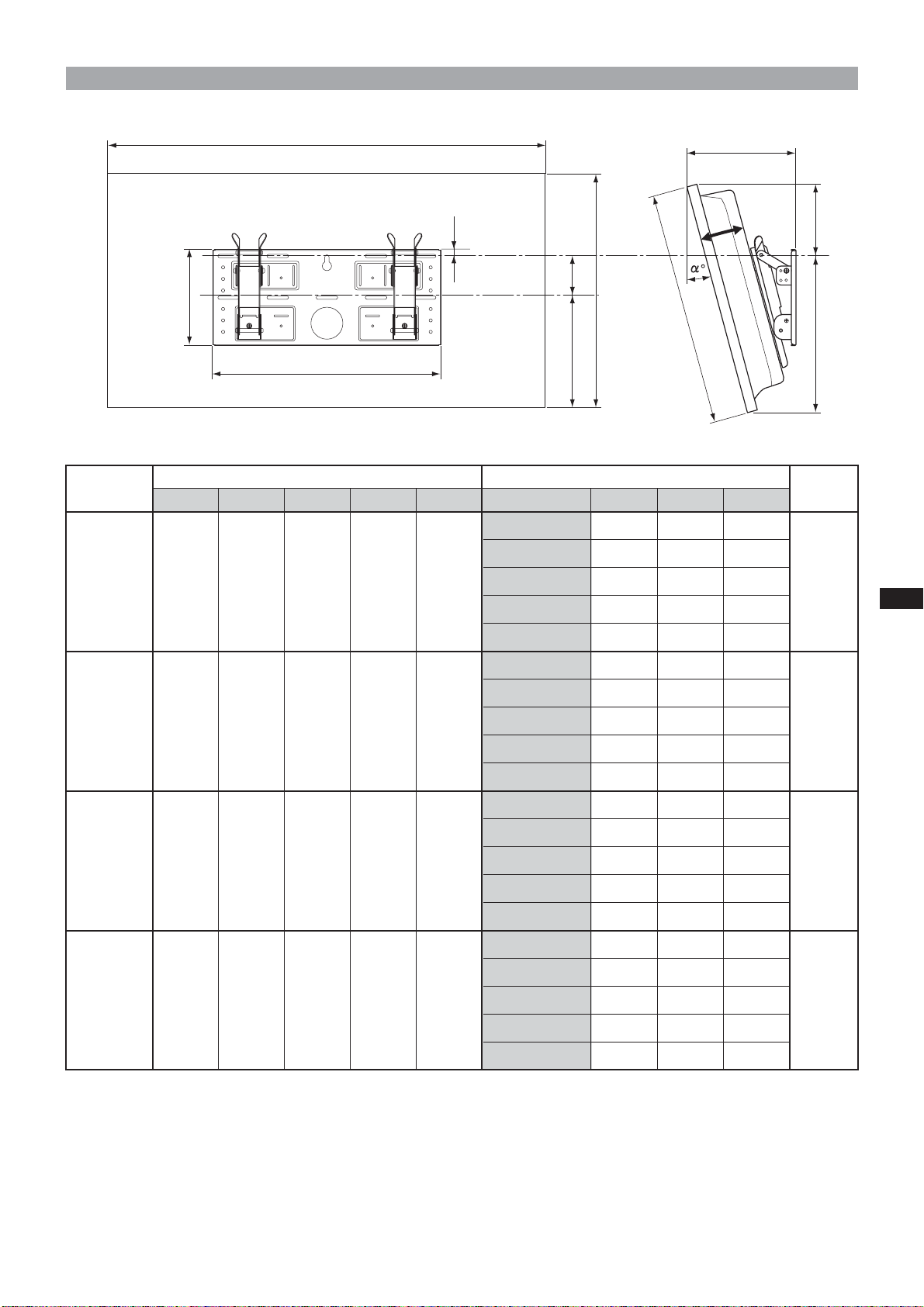
Tableau des dimensions pour l’installation de l’écran
A
14
F
C
D
210
B
B
E
500
Modèle
d’écran
KLV-30MR1 971 524 93 68 268 10° 206 167 352
Dimensions de l’écran
ABCDE
Unité : mm Longueur pour chaque angle de montage Unité : mm
Angle de montage (α°)
0° 147 188 336
5° 177 179 345
15° 234 152 258
FGH (×4)*
G
H
Poids
20 kg
(80 kg)
20° 260 135 363
0° 151 247 322
5° 186 237 331
KDL-L32MRX1
1 052 569 97 31 291 10° 219 225 339
KLV-L32MRX1
15° 252 209 345
20° 282 190 350
0° 167 150 280
5° 194 139 291
KLV-26HG2 790 430 118 65 215 10° 220 129 301
15° 244 122 310
20° 266 113 318
0° 165 281 323
5° 198 273 333
KLV-L32M1 835 604 111 -5 328 10° 230 262 342
15° 262 248 349
20° 292 231 356
23 kg
(92 kg)
15 kg
(60 kg)
17 kg
(68 kg)
* Le mur doit être suffisamment solide pour supporter au moins quatre fois le poids de l’écran que vous installez.
9 (FR)
Page 30
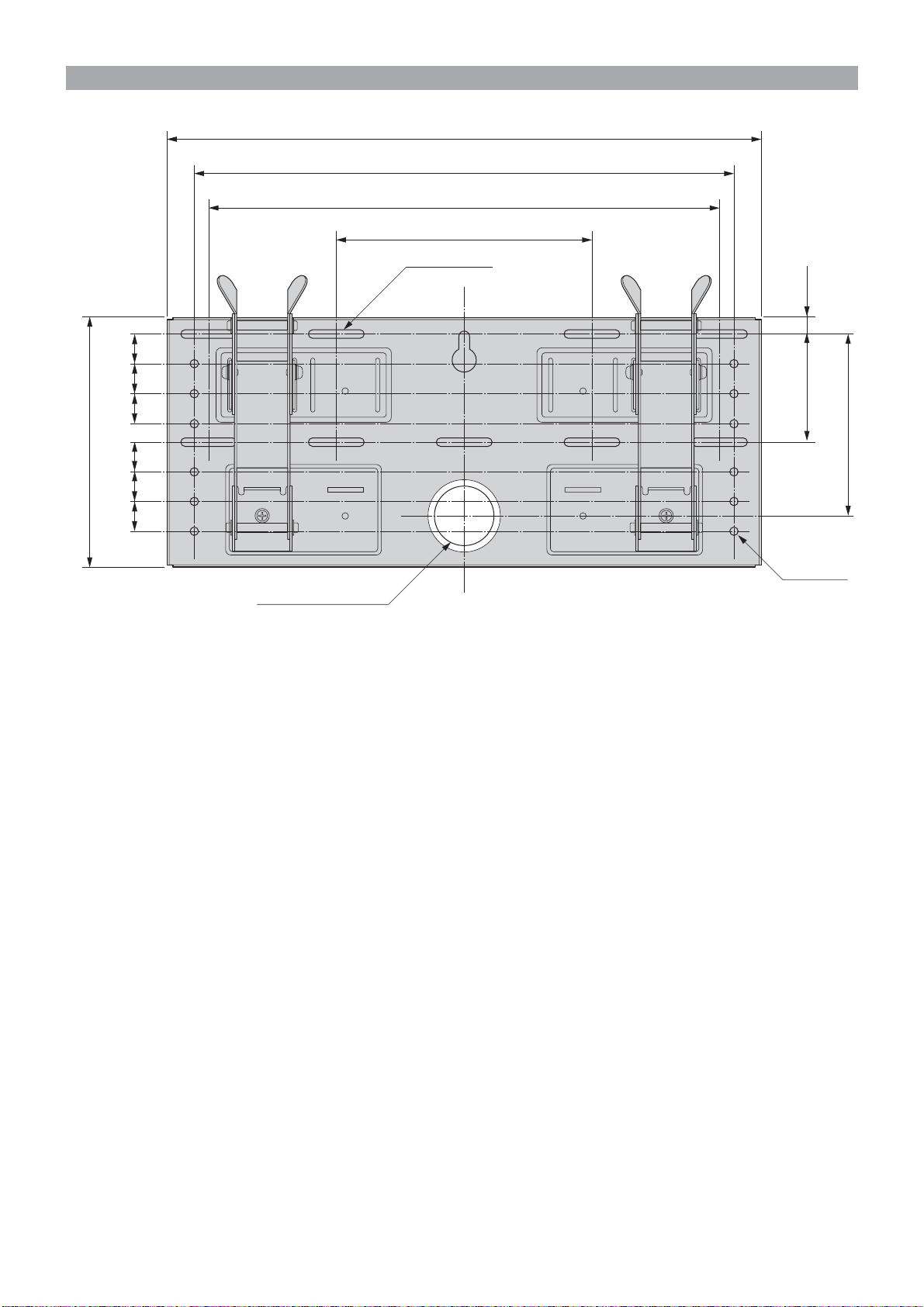
Schéma d’installation murale
252525
210
252525
Unité : mm
500
454
430
215
9-7×40
Trou allongé
91 14
148
12-φ7
φ60
Trou réservé au passage des
câbles
Reportez-vous au schéma ci-dessus pour connaître les spécifications de l’installation murale (en cas de
renforcement du mur ou de passage des câbles dans le mur).
AVERTISSEMENT
Le mur doit être suffisamment solide pour supporter au moins quatre fois le poids de l’écran que vous installez
(9 (FR)). Vérifiez que le mur peut supporter cette charge. Le cas échéant, renforcez-le.
10 (FR)
Page 31

Etape 4 : Installation de la plaque de fixation sur le
mur
Alignez la plaque de
fixation.
1
2
Trou utilisé pour fixer
temporairement la plaque de
fixation
Plaque de fixation
2
1
Fixez temporairement la plaque de
fixation au mur à l’aide d’une vis.
Alignez la plaque de fixation de
sorte qu’elle soit à niveau avec le
sol.
AVERTISSEMENT
• La vis utilisée dans cette procédure n’est pas livrée
avec l’appareil.
• Sélectionnez une vis convenant au matériau et à la
structure du mur.
Fixez la plaque de fixation au mur à
l’aide d’au moins quatre vis M6 ou
équivalentes (non fournies).
1Serrez les vis à fond de sorte que la plaque de
fixation puisse supporter le poids de l’écran.
2Serrez la vis utilisée en 1.
AVERTISSEMENT
Le mur doit être suffisamment solide pour supporter
au moins quatre fois le poids de l’écran que vous
installez (9 (FR)). Vérifiez que le mur peut supporter
cette charge. Le cas échéant, renforcez-le.
11 (FR)
Page 32

3
Bras
Limiteur
d’inclinaison
Embases A
et B
1
2
Ajustez l’inclinaison des bras.
Si vous souhaitez installer l’écran à la verticale, collé
contre le mur (0°), sautez les points 1 et 2 cidessous. Vérifiez que les bras sont solidement fixés à
la plaque de fixation.
1Retirez les quatre limiteurs d’inclinaison.
2Placez-les dans les trous de vis correspondant à
l’angle souhaité (5°, 10°, 15° ou 20°) et serrez-les à
fond.
Remarques
•L’angle d’inclinaison des bras droit et gauche doit
être le même.
• Faites attention à ne pas vous coincer les doigts lors
du réglage de l’angle des bras.
• Si vous utilisez un tournevis électrique pour serrer
les vis, le couple de serrage doit être réglé à 2 N•m
environ.
• Vérifiez que les embases sont solidement fixées à la
plaque de fixation.
12 (FR)
Page 33

Etape 5 : Dépose de l’écran du support de table
La procédure est différente suivant le modèle d’écran. Suivez la procédure
convenant à l’écran que vous installez.
KLV-26HG2
1Tirez sur un des coins inférieurs
(droite ou gauche) du couvercle
arrière. Tirez ensuite sur l’autre coin
inférieur.
2Maintenez le couvercle arrière des
deux mains et tirez-le vers vous. Le
couvercle se sépare de l’écran.
Remarque
Posez l’écran sur un tissu doux, face
orientée vers le sol, avant de passer à
l’étape 3.
3Retirez les deux petites vis du clip.
Retirez le clip du support de table.
4Retirez les cinq vis du support de
table.
5Soulevez légèrement le support, puis
tirez-le vers vous. Le support de table
se sépare de l’écran.
Remarques
• Couchez l’écran, face orientée vers le
sol, sur une surface plane et stable, en
laissant la base du support dépasser.
Le fait de placer la face de l’écran et la
base du support sur la même surface
plane entraîne une inclinaison de
l’écran, ce qui le rend instable et donc
dangereux.
• Lors du retrait du support de table,
tenez-le fermement.
1
2
3
Clip
Tissu doux
4
Vis retirées à
l’étape 4
5
13 (FR)
Page 34

KLV-30MR1
1Retirez les deux vis du support de table.
Remarque
Ne couchez pas l’écran lorsque vous
exécutez la procédure de démontage.
2Tout en maintenant l’embase du support,
soulevez légèrement l’écran, puis
éloignez-le du support. L’écran se sépare
du support de table. Prévoyez au moins
deux personnes pour tenir et porter
l’écran.
Remarques
• Lors de cette procédure, au moins deux
personnes doivent travailler ensemble.
• Lorsque vous soulevez l’écran, retenez
l’embase du support afin de ne pas le
soulever en même temps que l’écran.
3Retirez les quatre crochets situés sur le
couvercle arrière de l’écran.
Soulevez et
déplacez l’écran.
2
1
Embase du support
Remarque
Couchez l’écran, face orientée vers le sol, sur
un tissu doux.
3
Tissu doux
14 (FR)
Page 35

KDL-L32MRX1
KLV-L32MRX1
1Retirez les deux vis du support de table.
Remarque
Ne couchez pas l’écran lorsque vous
exécutez la procédure de démontage.
2Tout en maintenant l’embase du support,
soulevez légèrement l’écran, puis
éloignez-le du support. L’écran se sépare
du support de table. Prévoyez au moins
deux personnes pour tenir et porter
l’écran.
Remarques
• Lors de cette procédure, au moins deux
personnes doivent travailler ensemble.
• Lorsque vous soulevez l’écran, retenez
l’embase du support afin de ne pas le
soulever en même temps que l’écran.
3Retirez les deux crochets situés sur le
couvercle arrière de l’écran.
Soulevez et
déplacez l’écran.
2
1
Embase du support
KLV-L32M1
Remarque
Couchez l’écran, face orientée vers le sol, sur
un tissu doux.
Remarque
Posez l’écran sur un tissu doux, face
orientée vers le sol, avant de passer à
l’étape 1.
1Retirez les quatre vis du panneau
arrière de l’écran.
2Tirez le support vers vous. Le support
se sépare de l’écran.
3Retirez les quatre vis du panneau
arrière de l’écran.
3
Tissu doux
1
2
Tissu doux
Remarques
• Couchez l’écran, face orientée vers le
sol, sur une surface plane et stable, en
laissant la base du support dépasser.
Le fait de placer la face de l’écran et la
base du support sur la même surface
plane entraîne une inclinaison de
l’écran, ce qui le rend instable et donc
dangereux.
• Lors du retrait du support de table,
tenez-le fermement.
3
15 (FR)
Page 36

Etape 6 : Installation de l’écran sur la plaque de
fixation
AVERTISSEMENT
Ne branchez pas le cordon d’alimentation sur une prise de courant avant la fin de la procédure d’installation. Si
le cordon d’alimentation est coincé, cela risque de provoquer un court-circuit susceptible de causer un choc
électrique.
Faites attention à ne pas trébucher sur les câbles ou l’écran.
KLV-26HG2
1
Arrière de l’écran
Les vis fournies
(+PSW5 × L16)
Crochet de fixation
Tissu doux
KDL-L32MRX1/KLV-L32MRX1/KLV-30MR1
Les vis retirées à
l’Etape 5
.
Alignez les trous situés à l’arrière de
l’écran sur les crochets de montage
correspondants. Fixez-les sur le
l’écran à l’aide des quatre vis.
Pour le KLV-26HG2, utilisez les vis fournies (+PSW5 ×
L16). Pour le KDL-L32MRX1, le KLV-L32MRX1, le
KLV-30MR1 et le KLV-L32M1 utilisez les vis retirées à
l’Etape 5.
Remarques
• Couchez l’écran, face orientée vers le sol, sur un
tissu doux.
• Si vous utilisez un tournevis électrique pour serrer
les vis, le couple de serrage doit être réglé à 2 N•m
environ.
16 (FR)
Arrière de l’écran
KLV-L32M1
Arrière de l’écran
Crochet de fixation
Tissu doux
Les vis retirées à
l’Etape 5
Crochet de fixation
Tissu doux
Page 37

2
Trou réservé au passage
des câbles
Raccordement du cordon
d’alimentation et des câbles fournis.
Raccordez le cordon d’alimentation et les câbles aux
prises correspondantes à l’arrière de l’écran. Pour
obtenir davantage de détails sur le raccordement des
câbles, reportez-vous au mode d’emploi de l’écran.
Si vous faites passer les câbles dans un mur, prévoyez
un trou dans le mur pour faire cheminer les câbles (10
(FR)).
Remarques
• Il n’est plus possible de raccorder les câbles à
l’écran après l’avoir installé sur la plaque de
fixation.
• Confiez le passage des câbles dans le mur à un
technicien qualifié.
17 (FR)
Page 38

3
2
1
N’enfoncez
pas les vis trop
loin.
Montage de l’écran sur la plaque
de fixation.
1Pour verrouiller temporairement les bras,
placez depuis l’extérieur les deux vis de
fixation (+B5 × L12, fournies) dans les trous
situés dans les embases B.
2Suspendez les crochets supérieurs de fixation
aux axes supérieurs des bras.
3Suspendez les crochets inférieurs de fixation
aux axes inférieurs des bras.
4Tout en poussant l’écran vers la plaque de
fixation, soulevez-le doucement et suspendez
les crochets inférieurs aux axes inférieurs.
5Vérifiez que les huit crochets sont
correctement suspendus aux axes
correspondants.
6Serrez les vis de fixation montées en 1.
Remarque
Si vous enfoncez les vis de fixation trop loin
dans les trous (1), l’extrémité des vis risque de
vous gêner lorsque vous suspendrez les crochets
inférieurs aux axes (4).
4
3
6
18 (FR)
Page 39

Vérifiez que toutes les procédures de montage ont
été réalisées correctement
Vérifiez les points suivants.
• Les huit crochets sont bien suspendus aux axes correspondants.
• Les câbles de ne sont pas tordus ni pincés.
• Les deux vis de fixation sont serrées à fond.
AVERTISSEMENT
Si l’écran n’est pas correctement installé, il risque de tomber et d’entraîner des blessures ou des dommages
matériels. Si les câbles ne sont pas correctement acheminés, un court-circuit risque de se produire et d’entraîner
un incendie ou une électrocution. Pour votre sécurité, vérifiez que toutes les procédures ont été correctement
suivies.
19 (FR)
Page 40

Dépose de l’écran
1
2
3
A l’attention des
revendeurs Sony
Débranchez le cordon
d’alimentation de la prise secteur.
Retirez les deux vis de fixation.
Deux personnes au moins doivent
soulever l’écran et le retirer de la
plaque de fixation.
AVERTISSEMENT
• Prévoyez au moins deux personnes pour tenir et
porter l’écran.
• Lors de la dépose de l’écran, prenez soin de ne pas
entraîner les câbles.
• Lors de la dépose de l’écran, faites attention à ne
pas vous blesser les mains ou les doigts.
20 (FR)
Page 41

Spécifications
Unité : mm
Poids : 3,4 kg
500
210
245
270
40
La conception et les spécifications sont sujettes à modifications sans préavis.
21 (FR)
Page 42

Danke, dass Sie sich für dieses Produkt entschieden haben.
Hinweis an Kunden
Zur Installation dieses Produkts sind entsprechende Kenntnisse erforderlich. Lassen Sie die
Installationsarbeiten unbedingt von Ihrem Sony-Händler oder entsprechenden Fachleuten ausführen und
beachten Sie bei der Installation die nötigen Sicherheitsvorkehrungen. Sony übernimmt keine Haftung für
Verletzungen bzw. Sachschäden, die durch unsachgemäßen Umgang mit dem Produkt oder eine fehlerhafte
Montage entstehen. Ihre gesetzlich vorgeschriebenen Rechte (sofern vorhanden) bleiben davon unberührt.
ACHTUNG
Wenn die Sicherheitsmaßnahmen nicht eingehalten werden und das Produkt unsachgemäß verwendet wird,
besteht Feuergefahr und die Gefahr schwerer Verletzungen.
Diese Gebrauchsanweisung enthält wichtige Sicherheitshinweise, deren Beachtung Unfälle verhindert und die
richtige Handhabung des Produkts gewährleistet. Lesen Sie diese Anweisungen sorgfältig durch und verwenden
Sie das Produkt sachgemäß. Bewahren Sie diese Gebrauchsanweisung zum späteren Nachschlagen auf.
Für Sony-Händler
Zur Installation dieses Produkts sind entsprechende Kenntnisse erforderlich. Lesen Sie diese Gebrauchsanweisung
unbedingt sorgfältig durch, damit eine sichere Ausführung der Arbeiten gewährleistet ist. Der Hersteller
übernimmt keine Haftung für Verletzungen bzw. Sachschäden, die durch unsachgemäßen Umgang mit dem
Produkt oder eine fehlerhafte Installation verursacht werden. Ihre gesetzlich vorgeschriebenen Rechte (sofern
vorhanden) bleiben davon unberührt. Händigen Sie diese Gebrauchsanweisung nach der Installation bitte an den
Kunden aus.
Diese Wandhalterung wurde von Sony ausschließlich für die angegebenen Geräte konzipiert. Verwenden Sie
die Halterung ausschließlich mit folgenden Geräten.
Spezifizierte Produkte: LCD Colour TV (KDL-L32MRX1/KLV-L32MRX1/KLV-30MR1/KLV-26HG2/KLV-L32M1)
Sicherheit
Bei der Entwicklung von Sony-Produkten wird besonderer Wert auf den Faktor Sicherheit gelegt.
Wenn ein Produkt jedoch nicht sachgemäß verwendet wird, kann es durch Feuer, einen elektrischen Schlag, das
Umkippen oder das Herunterfallen des Geräts zu schweren Verletzungen kommen. Beachten Sie bitte unbedingt
die Sicherheitsmaßnahmen, um solche Unfälle zu vermeiden.
2 (DE)
Page 43

Für Kunden
ACHTUNG
Wenn Sie die folgenden Sicherheitsmaßnahmen nicht beachten, besteht die Gefahr von schweren oder
gar tödlichen Verletzungen durch Feuer, einen elektrischen Schlag oder eine Explosion.
Lassen Sie die Installationsarbeiten unbedingt von qualifizierten Fachleuten
ausführen und halten Sie kleine Kinder bei der Installation unbedingt fern.
Wenn die Wandhalterung nicht von qualifizierten Fachleuten installiert
wird, besteht die Gefahr folgender Unfälle.
• Das Fernsehgerät kann bei einem Erdbeben herunterfallen und schwere
Verletzungen wie Blutergüsse oder Knochenbrüche verursachen.
•Wenn die Wand, an der die Wandhalterung installiert wird, nicht stabil,
nicht eben oder nicht senkrecht zum Fußboden ist, kann das
Fernsehgerät herunterfallen. Dabei besteht die Gefahr von Verletzungen
oder Sachschäden. Die Wand muss eine Tragfähigkeit von mindestens
dem Vierfachen (4) des Gewichts des Fernsehgeräts aufweisen (KDLL32MRX1/KLV-L32MRX1: 23 kg × 4 = 92 kg, KLV-30MR1: 20 kg × 4 =
80 kg, KLV-26HG2: 15 kg × 4 = 60 kg, KLV-L32M1: 17 kg × 4 = 68 kg).
•Wenn die Wandhalterung nicht ausreichend stabil installiert wird, kann
das Fernsehgerät herunterfallen. Dabei besteht die Gefahr von
Verletzungen oder Sachschäden.
Lassen Sie die Installationsarbeiten beim Versetzen oder Abnehmen der
Wandhalterung unbedingt von qualifizierten Fachleuten ausführen.
Wenn die Wandhalterung von anderen Personen als qualifizierten Fachleuten abgenommen oder transportiert
wird, kann das Fernsehgerät herunterfallen und Verletzungen oder Sachschäden verursachen. Zum Abnehmen
bzw. Transportieren der Wandhalterung sind mindestens zwei Personen erforderlich.
Achten Sie darauf, dass keinerlei Flüssigkeit in das Fernsehgerät gelangt.
Wenn das Fernsehgerät nass wird, besteht Feuergefahr oder die Gefahr eines elektrischen Schlags.
Entfernen Sie nach der Montage des Fernsehgeräts keine Schrauben usw.
Andernfalls kann das Fernsehgerät herunterfallen.
Versuchen Sie nicht, die Komponenten der Wandhalterung zu zerlegen oder
zu modifizieren.
Andernfalls kann die Wandhalterung herunterfallen und es besteht die
Gefahr von Sachschäden und Verletzungen.
DE
Deutsch
Installieren Sie an der Halterung ausschließlich die angegebenen Geräte.
Diese Wandhalterung wurde ausschließlich für die angegebenen Geräte konzipiert. Wenn Sie andere als die
angegebenen Geräte an der Wandhalterung installieren, kann sie herunterfallen und es besteht die Gefahr von
Sachschäden und Verletzungen.
3 (DE)
Page 44

Blockieren Sie nicht die Lüftungsöffnungen des Fernsehgeräts.
Wenn Sie die Lüftungsöffnungen am Fernsehgerät blockieren, indem Sie
eine Tischdecke oder etwas Ähnliches darauf legen, kann sich das
Fernsehgerät überhitzen. In diesem Fall besteht Brandgefahr.
Befestigen Sie zusätzlich zu dem Fernsehgerät keine weiteren Lasten an der
Wandhalterung.
Andernfalls kann das Fernsehgerät herunterfallen und es besteht die
Gefahr von Sachschäden und Verletzungen.
Lehnen und hängen Sie sich nicht an das Fernsehgerät.
Das Fernsehgerät könnte auf Sie fallen und schwere Verletzungen
verursachen.
Um Feuergefahr und die Gefahr eines elektrischen Schlags zu vermeiden,
setzen Sie das Fernsehgerät weder Regen noch sonstiger Feuchtigkeit aus.
Wenn das Fernsehgerät nass wird, besteht Feuergefahr oder die Gefahr eines elektrischen Schlags.
Stellen Sie das Fernsehgerät nicht in heißer, feuchter oder übermäßig
staubiger Umgebung auf. Stellen Sie das Fernsehgerät nicht an Orten auf, an
denen es mechanischen Vibrationen ausgesetzt ist.
Andernfalls besteht Feuergefahr oder die Gefahr eines elektrischen Schlags.
Halten Sie brennbare Materialien bzw. offenes Feuer (z. B. Kerzen) vom
Fernsehgerät fern.
Um Feuergefahr zu vermeiden, halten Sie brennbare Materialien bzw. offenes Feuer (z. B. Kerzen) vom
Fernsehgerät fern.
4 (DE)
Page 45

VORSICHT
Wenn Sie die folgenden Sicherheitsmaßnahmen nicht beachten, besteht die Gefahr von Verletzungen
und Sachschäden.
Installieren Sie die Wandhalterung nicht an Wänden, bei denen die Ecken
oder die Seiten des Fernsehgeräts über die Wandfläche hinausragen.
Installieren Sie die Wandhalterung nicht an Wänden, wie z. B. einer Säule,
bei denen die Ecken oder die Seiten des Fernsehgeräts über die Wandfläche
hinausragen. Andernfalls könnten Personen oder Gegenstände gegen die
vorstehenden Ecken oder Seiten des Fernsehgeräts stoßen. Dabei besteht
die Gefahr von Verletzungen und Sachschäden.
Wenden Sie bei Reinigungs- bzw. Wartungsarbeiten nicht zu viel Kraft an.
Drücken Sie nicht zu stark auf die Oberseite des Fernsehgeräts.
Andernfalls kann das Fernsehgerät herunterfallen und es besteht die Gefahr von Sachschäden und Verletzungen.
Montieren Sie das Fernsehgerät nicht über oder unter einer Klimaanlage.
Andernfalls ist das Fernsehgerät dem Luftstrom von der Klimaanlage ausgesetzt. Dies könnte zu Fehlfunktionen
des Fernsehgeräts führen.
Sicherheitsmaßnahmen
•Wenn das Fernsehgerät längere Zeit an der Wandhalterung montiert bleibt, kann sich die Wand hinter und über
dem Fernsehgerät verfärben und die Tapete kann sich von der Wand lösen. Dies hängt vom Material der Wand
ab. Wenn die Wandhalterung später von der Wand abgenommen wird, bleiben die Bohrlöcher sichtbar.
•Wenn hinter der Wand 300-Ohm-Speisekabel verlegt sind, empfiehlt es sich, diese durch 75-Ohm-Koaxialkabel
zu ersetzen.
Wenn es nicht möglich ist, die 300-Ohm-Speisekabel auszutauschen, achten Sie vor der Installation darauf, dass
zwischen dem Fernsehgerät und den Speisekabeln hinter der Wand ausreichend Platz ist.
Lassen Sie sich von den mit der Installation betrauten Fachleuten bei der Wahl der Montageposition beraten,
damit das Fernsehgerät keinen Funkstörungen ausgesetzt ist.
5 (DE)
Page 46

Installieren der Wandhalterung
Für Sony-Händler
ACHTUNG Hinweis an Kunden
Zur Installation dieses Produkts sind entsprechende Kenntnisse erforderlich. Lassen Sie die
Installationsarbeiten unbedingt von Ihrem Sony-Händler oder entsprechenden Fachleuten ausführen und
beachten Sie bei der Installation die nötigen Sicherheitsvorkehrungen.
Für Sony-Händler
Die folgenden Anweisungen richten sich ausschließlich an Sony-Händler. Lesen Sie die oben erläuterten
Sicherheitsmaßnahmen sorgfältig durch und beachten Sie bei der Installation, der Wartung und der
Überprüfung dieses Produkts alle geeigneten Sicherheitsmaßnahmen.
Beachten Sie beim Installieren der Wandhalterung an der Wand unbedingt
die Anweisungen in dieser Gebrauchsanweisung.
Wenn Schrauben nicht fest sitzen oder gar herausfallen, kann die
Wandhalterung herunterfallen und Verletzungen oder Sachschäden
verursachen. Verwenden Sie unbedingt Schrauben, die für das Material der
Wand geeignet sind, und befestigen Sie die Halterung sicher mit
mindestens fünf M6-Schrauben oder entsprechenden Schrauben.
Achten Sie darauf, das Netzkabel und das Bildschirmkabel nicht
einzuklemmen.
Wenn das Netzkabel oder das Bildschirmkabel zwischen dem Gerät und
der Wand eingeklemmt wird oder mit Gewalt gebogen oder verdreht wird,
wird möglicherweise die Kabelisolierung beschädigt. Die blanken Drähte
können zu einem Kurzschluss führen und die Kabel können brechen. In
diesem Fall besteht Feuergefahr oder die Gefahr eines elektrischen Schlags.
Verwenden Sie die mitgelieferten Schrauben und Montageteile unbedingt
wie in dieser Gebrauchsanweisung erläutert. Wenn Sie andere Teile
verwenden, kann das Fernsehgerät herunterfallen. Dabei besteht die Gefahr
von Verletzungen bzw. Schäden am Gerät.
Gehen Sie bei der Montage der Halterung unbedingt genau nach den
Anweisungen in dieser Gebrauchsanweisung vor.
Wenn Schrauben nicht fest sitzen oder gar herausfallen, kann das Fernsehgerät herunterfallen. Dabei besteht die
Gefahr von Verletzungen bzw. Schäden am Gerät.
Ziehen Sie alle Schraubenbolzen und Schrauben unbedingt fest an.
Andernfalls kann das Fernsehgerät herunterfallen. Dabei besteht die Gefahr von Verletzungen bzw. Schäden am
Gerät.
Schützen Sie das Fernsehgerät bei der Montage vor Stößen.
Wenn das Fernsehgerät Stößen ausgesetzt wird, kann es herunterfallen oder beschädigt werden. Außerdem besteht
die Gefahr von Verletzungen.
6 (DE)
Page 47

Montieren Sie das Fernsehgerät unbedingt an einer senkrechten und ebenen
Wand.
Andernfalls kann das Fernsehgerät herunterfallen und Verletzungen verursachen.
Sichern Sie die Kabel ordnungsgemäß, nachdem das Fernsehgerät korrekt
installiert wurde.
Wenn jemand über die Kabel stolpert oder sich Gegenstände darin verfangen, besteht Verletzungsgefahr.
Klemmen Sie sich bei der Montage nicht die Hände oder Finger ein.
Gehen Sie bei der Montage der Wandhalterung und bei der Installation des Fernsehgeräts bitte vorsichtig vor, damit
Sie sich nicht an Händen oder Fingern verletzen.
Die Schrauben, die zum Befestigen der Wandhalterung an der Wand benötigt
werden, sind nicht im Lieferumfang enthalten.
Verwenden Sie zur Installation der Wandhalterung für Material und Struktur der Wand geeignete Schrauben.
Schritt 1: Überprüfen, ob Sie alle für die Installation
1
2
benötigten Teile haben
Halten Sie mindestens fünf M6Schrauben oder entsprechende
Schrauben (nicht mitgeliefert) und
einen Schraubenzieher bereit.
Wählen Sie Schrauben aus, die für
das Material der Wand geeignet
sind.
Öffnen Sie die Verpackung und
vergewissern Sie sich, dass folgende
Teile enthalten sind.
Schrauben
(+B5 × L12) (2)
Montageplatte (1) Befestigungsstreben (2)
Schrauben (+PSW5 × L16) (4)
(beim KLV-26HG2)
7 (DE)
Page 48

Schritt 2: Einstellen der Position der Armstützen
(nur beim KLV-26HG2 und KLV-L32M1)
Wenn Sie einen KDL-L32MRX1, KLV-
1
Armstütze A
Armstütze A
Armstütze A
Armstütze A
3
5
3
Armstütze B
1
Armstütze B
2
Arm
4
Arm
2
Armstütze B
1
Neigungseinstellschraube
4
Armstütze B
3
5
Neigungseinstellschraube
L32MRX1 oder KLV-30MR1 installieren,
lassen Sie Schritt 2 aus und fahren mit
Schritt 3 fort.
1Entfernen Sie die vier
Neigungseinstellschrauben (zwei pro
Armstütze).
2Entfernen Sie die vier Schrauben, mit
denen die Armstützen an der
Montageplatte befestigt sind.
3Nehmen Sie die Armstützen A ab und
setzen Sie sie nach innen weisend in die
Kerben ein. Setzen Sie die Arme und die
Armstützen B auf die Armstützen A.
4Befestigen Sie die Armstützen mit den in
2 entfernten vier Schrauben an der
Montageplatte.
5Befestigen Sie die Arme mit den in 1
entfernten vier
Neigungseinstellschrauben an den
Armstützen.
Hinweise
•Wenn Sie ein anderes Fernsehgerät als
den KLV-26HG2 oder KLV-L32M1
installieren, lassen Sie Schritt 2 aus.
•Wenn Sie die Schrauben mit einem
elektrischen Schraubendreher anziehen,
muss das Drehmoment etwa 2 N•m
betragen.
Schritt 3: Festlegen der Montageposition
1
8 (DE)
Maßeinheit: mm
100
300
100
100
Lassen Sie ausreichend Platz um das
Fernsehgerät. Halten Sie zwischen
dem Fernsehgerät und der Decke
bzw. den vorstehenden Teilen der
Wand unbedingt mindestens die in
der Abbildung gezeigten Abstände
ein.
Tipp
Installationsabmessungen für das Fernsehgerät finden
Sie im Aufriss und in der Tabelle (9 (DE)).
Page 49

Aufriss und Tabelle der Installationsabmessungen für das Fernsehgerät
Modell des
Fernsehgeräts
A
14
210
500
Abmessungen des Fernsehgeräts
ABCDE
Maßeinheit: mm
Montagewinkel (α°)
D
B
B
E
Abmessungen bei verschiedenen
Montagewinkeln
FGH
0° 147 188 336
F
C
Maßeinheit: mm
G
H
Gewicht
(×4)*
5° 177 179 345
KLV-30MR1 971 524 93 68 268 10° 206 167 352
15° 234 152 258
20° 260 135 363
0° 151 247 322
5° 186 237 331
KDL-L32MRX1
1.052 569 97 31 291 10° 219 225 339
KLV-L32MRX1
15° 252 209 345
20° 282 190 350
0° 167 150 280
5° 194 139 291
KLV-26HG2 790 430 118 65 215 10° 220 129 301
15° 244 122 310
20° 266 113 318
0° 165 281 323
5° 198 273 333
KLV-L32M1 835 604 111 -5 328 10° 230 262 342
15° 262 248 349
20 kg
(80 kg)
23 kg
(92 kg)
15 kg
(60 kg)
17 kg
(68 kg)
20° 292 231 356
* Die Tragfähigkeit der Wand muss mindestens dem Vierfachen des Gewichts des Fernsehgeräts entsprechen, das
Sie installieren.
9 (DE)
Page 50

Diagramm für Wandmontage
252525
210
252525
Maßeinheit: mm
500
454
430
215
9-7×40
Langloch
91 14
148
12-φ7
φ60
Aussparung für Kabelverlegung
Informationen zu den Anforderungen bei einer Wandmontage (Verstärken der Wand oder Verlegen von Kabeln in
der Wand) sind im Diagramm oben enthalten.
ACHTUNG
Die Tragfähigkeit der Wand muss mindestens dem Vierfachen des Gewichts des Fernsehgeräts entsprechen, das Sie
installieren (9 (DE)). Vergewissern Sie sich, dass die Wand ausreichend stabil ist. Wenn nötig, muss die Wand
verstärkt werden.
10 (DE)
Page 51

Schritt 4: Installier en der Montageplatte an der Wand
Richten Sie die
Montageplatte aus.
1
2
Bohrung für vorübergehendes
Anbringen der Montageplatte
Montageplatte
2
1
Befestigen Sie die Montageplatte
vorübergehend mit einer Schraube
an der Wand. Richten Sie die
Montageplatte so aus, dass sie
waagrecht angebracht ist.
ACHTUNG
• Die hierfür benötigte Schraube wird nicht mit dem
Gerät mitgeliefert.
•Wählen Sie eine Schraube aus, die für das Material
und die Struktur der Wand geeignet ist.
Befestigen Sie die Montageplatte
mit mindestens vier M6-Schrauben
oder entsprechenden Schrauben
(nicht mitgeliefert) an der Wand.
1Ziehen Sie die Schrauben fest an, so dass die
Montageplatte das Gewicht des Fernsehgeräts
tragen kann.
2Ziehen Sie die in 1 verwendete Schraube an.
ACHTUNG
Die Tragfähigkeit der Wand muss mindestens dem
Vierfachen des Gewichts des Fernsehgeräts
entsprechen, das Sie installieren (9 (DE)).
Ve rgewissern Sie sich, dass die Wand ausreichend
stabil ist. Wenn nötig, muss die Wand verstärkt
werden.
11 (DE)
Page 52

3
Arm
Neigungseinstellschraube
Armstützen
A und B
1
2
Stellen Sie die Neigung der Arme
ein.
Wenn Sie das Fernsehgerät vertikal, also an der Wand
anliegend (0°) installieren wollen, lassen Sie 1 und 2
unten aus. Überprüfen Sie, ob die Arme fest an der
Montageplatte angebracht sind.
1Entfernen Sie alle vier Neigungseinstellschrauben.
2Setzen Sie sie in die Bohrungen für den
gewünschten Winkel (5°, 10°, 15° oder 20°) ein und
ziehen Sie sie fest an.
Hinweise
• Der Winkel des linken und der des rechten Arms
müssen übereinstimmen.
• Achten Sie darauf, sich beim Einstellen der
Armwinkel nicht die Finger einzuklemmen.
•Wenn Sie die Schrauben mit einem elektrischen
Schraubendreher anziehen, muss das Drehmoment
etwa 2 N•m betragen.
• Überprüfen Sie, ob die Armstützen fest an der
Montageplatte angebracht sind.
12 (DE)
Page 53

Schritt 5: Abnehmen des Fernsehgeräts vom
Tischständer
Das Verfahren variiert je nach Modell des Fernsehgeräts. Gehen Sie nach
dem Verfahren vor, das für das zu installierende Fernsehgerät geeignet ist.
KLV-26HG2
1Ziehen Sie an einer der Ecken unten
(rechts oder links) an der hinteren
Abdeckung. Ziehen Sie dann an der
anderen Ecke unten.
2Halten Sie die hintere Abdeckung mit
beiden Händen und ziehen Sie sie auf
sich zu. Die hintere Abdeckung löst
sich vom Fernsehgerät.
Hinweis
Legen Sie das Fernsehgerät mit der
Mattscheibe nach unten auf ein weiches
Tuch, bevor Sie mit 3 fortfahren.
3Entfernen Sie die beiden kleinen
Schrauben von der Klammer. Nehmen
Sie die Klammer vom Tischständer ab.
4Entfernen Sie die fünf Schrauben vom
Tischständer.
5Heben Sie den Ständer etwas an und
ziehen Sie ihn dann auf sich zu. Der
Ständer löst sich vom Fernsehgerät.
Hinweise
• Legen Sie das Fernsehgerät mit der
Mattscheibe nach unten auf eine
stabile und ebene Oberfläche, so dass
der Fuß des Ständers in die Luft ragt.
Wenn Sie die Mattscheibe und den
Fuß des Ständers auf derselben
Oberfläche ablegen, liegt das
Fernsehgerät schräg und damit
instabil. Dies kann gefährlich werden.
• Halten Sie den Tischständer gut fest,
wenn Sie ihn vom Fernsehgerät
abmontieren.
1
2
3
In 4 entfernte
Schrauben
Klammer
Weiches Tuch
4
5
13 (DE)
Page 54

KLV-30MR1
1Entfernen Sie die beiden Schrauben vom
Tischständer.
Hinweis
Legen Sie das Fernsehgerät beim Ausführen
dieses Verfahrens nicht ab.
2Halten Sie den Fuß des Ständers fest,
heben Sie das Fernsehgerät leicht an und
entfernen Sie es vom Ständer. Das
Fernsehgerät löst sich vom Ständer. Zum
Halten und Tragen des Fernsehgeräts sind
mindestens zwei Personen erforderlich.
Hinweise
• Dieses Verfahren muss von mindestens
zwei Personen ausgeführt werden.
•Halten Sie beim Anheben des
Fernsehgeräts den Fuß des Ständers fest,
so dass er nicht zusammen mit dem
Fernsehgerät angehoben wird.
3Entfernen Sie die vier Haken an der
Rückseite des Fernsehgeräts.
Anheben und
herausziehen.
2
1
Fuß des Ständers
3
Hinweis
Legen Sie das Fernsehgerät mit der
Mattscheibe nach unten auf ein weiches
Tuch.
Weiches
Tuch
14 (DE)
Page 55

KDL-L32MRX1
KLV-L32MRX1
1Entfernen Sie die beiden Schrauben vom
Tischständer.
Hinweis
Legen Sie das Fernsehgerät beim Ausführen
dieses Verfahrens nicht ab.
2Halten Sie den Fuß des Ständers fest,
heben Sie das Fernsehgerät leicht an und
entfernen Sie es vom Ständer. Das
Fernsehgerät löst sich vom Ständer. Zum
Halten und Tragen des Fernsehgeräts sind
mindestens zwei Personen erforderlich.
Hinweise
• Dieses Verfahren muss von mindestens
zwei Personen ausgeführt werden.
•Halten Sie beim Anheben des
Fernsehgeräts den Fuß des Ständers fest,
so dass er nicht zusammen mit dem
Fernsehgerät angehoben wird.
3Entfernen Sie die beiden Haken an der
Rückseite des Fernsehgeräts.
Anheben und
herausziehen.
2
1
Fuß des Ständers
3
KLV-L32M1
Hinweis
Legen Sie das Fernsehgerät mit der
Mattscheibe nach unten auf ein weiches
Tuch.
Hinweis
Legen Sie das Fernsehgerät mit der
Mattscheibe nach unten auf ein weiches
Tuch, bevor Sie mit 1 fortfahren.
1Entfernen Sie die vier Schrauben an
der Rückseite des Fernsehgeräts.
2Ziehen Sie den Ständer auf sich zu.
Der Ständer löst sich vom
Fernsehgerät.
3Entfernen Sie die vier Schrauben an
der Rückseite des Fernsehgeräts.
Hinweise
• Legen Sie das Fernsehgerät mit der
Mattscheibe nach unten auf eine
stabile und ebene Oberfläche, so dass
der Fuß des Ständers in die Luft ragt.
Wenn Sie die Mattscheibe und den
Fuß des Ständers auf derselben
Oberfläche ablegen, liegt das
Fernsehgerät schräg und damit
instabil. Dies kann gefährlich werden.
• Halten Sie den Tischständer gut fest,
wenn Sie ihn vom Fernsehgerät
abmontieren.
Weiches
Tuch
1
2
Weiches Tuch
3
15 (DE)
Page 56

Schritt 6: Installieren des Fernsehgeräts auf der
Montageplatte
ACHTUNG
Schließen Sie das Netzkabel immer erst an eine Netzsteckdose an, wenn die Installation abgeschlossen ist.
Wenn das Netzkabel eingeklemmt wird, kann ein Kurzschluss auftreten, der wiederum einen elektrischen
Schlag verursachen kann.
Achten Sie darauf, nicht über die Kabel oder das Fernsehgerät zu stolpern.
KLV-26HG2
1
Rückseite des Fernsehgeräts
Mitgelieferte Schrauben
(+PSW5 × L16)
Befestigungsstreben
Weiches Tuch
KDL-L32MRX1/KLV-L32MRX1/KLV-30MR1
In Schritt 5 entfernte
Schrauben
Richten Sie die Bohrungen der
Befestigungsstreben an den
entsprechenden Bohrungen an der
Rückseite des Fernsehgeräts aus.
Befestigen Sie die Streben mit vier
Schrauben am Fernsehgerät.
Verwenden Sie beim KLV-26HG2 die mitgelieferten
Schrauben (+PSW5 × L16). Verwenden Sie beim KDLL32MRX1, KLV-L32MRX1, KLV-30MR1 bzw. KLVL32M1 die in Schritt 5 entfernten Schrauben.
Hinweise
• Legen Sie das Fernsehgerät mit der Mattscheibe
nach unten auf ein weiches Tuch.
•Wenn Sie die Schrauben mit einem elektrischen
Schraubendreher anziehen, muss das Drehmoment
etwa 2 N•m betragen.
16 (DE)
Rückseite des Fernsehgeräts
KLV-L32M1
Rückseite des Fernsehgeräts
Befestigungsstreben
Weiches Tuch
In Schritt 5 entfernte
Schrauben
Befestigungsstreben
Weiches Tuch
Page 57

2
Aussparung für Kabelverlegung
Schließen Sie das mitgelieferte
Netzkabel und sonstige Kabel an.
Schließen Sie das Netzkabel und die sonstigen Kabel
an die entsprechenden Buchsen an der Rückseite des
Fernsehgeräts an. Einzelheiten zum Anschließen der
Kabel finden Sie in der Bedienungsanleitung zu Ihrem
Fernsehgerät.
Wenn Sie die Kabel in der Wand verlegen wollen,
führen Sie sie durch ein für die Verkabelung gebohrtes
Loch in der Wand (10 (DE)).
Hinweise
• Sie können die Kabel nicht mehr an das
Fernsehgerät anschließen, wenn dieses auf der
Montageplatte installiert ist.
• Lassen Sie die Verkabelung in der Wand von
qualifizierten Fachleuten ausführen.
17 (DE)
Page 58

3
2
4
1
Schieben Sie
die Schrauben
nicht zu weit
hinein.
Montieren Sie das Fernsehgerät
auf der Montageplatte.
1Um die Arme vorübergehend zu arretieren,
setzen Sie die beiden Befestigungsschrauben
(+B5 × L12, mitgeliefert) von außen in die
Bohrungen an den Armstützen B ein.
2Hängen Sie die oberen Haken der
Befestigungsstreben in die oberen Schäfte der
Arme ein.
3Setzen Sie die unteren Haken der
Befestigungsstreben auf die unteren Schäfte
der Arme.
4Drücken Sie das Fernsehgerät auf die
Montageplatte, heben Sie es langsam an und
hängen Sie die unteren Haken in die unteren
Schäfte ein.
5Ve rgewissern Sie sich, dass alle Haken korrekt
in den entsprechenden Schäften eingehängt
sind.
6Ziehen Sie die in 1 angebrachten
Befestigungsschrauben an.
Hinweis
Wenn Sie die Befestigungsschrauben zu weit in
die Bohrungen schieben (1), sind die Spitzen
der Schrauben im Weg, wenn Sie die unteren
Haken in die Schäfte einhängen (4).
3
6
18 (DE)
Page 59

Überprüfen, ob alle Schritte korrekt ausgeführt
wurden
Überprüfen Sie Folgendes:
• Alle Haken müssen fest in den entsprechenden Schäften eingehängt sein.
• Die Kabel dürfen nicht verdreht oder eingeklemmt sein.
• Die beiden Befestigungsschrauben müssen fest angezogen sein.
ACHTUNG
Wenn das Gerät nicht richtig installiert wurde, kann es herunterfallen und beschädigt werden oder
Verletzungen verursachen. Wenn die Kabel nicht richtig verlegt sind, kann es zu einem Kurzschluss kommen
und es besteht Feuergefahr oder die Gefahr eines elektrischen Schlags. Überprüfen Sie aus Sicherheitsgründen,
ob alle Schritte korrekt ausgeführt wurden.
19 (DE)
Page 60

Abnehmen des Fernsehgeräts
1
2
3
Für Sony-Händler
Ziehen Sie das Netzkabel aus der
Netzsteckdose.
Entfernen Sie die beiden
Befestigungsschrauben.
Mindestens zwei Personen sind
erforderlich, um das Fernsehgerät
anzuheben und von der
Montageplatte abzunehmen.
ACHTUNG
• Zum Halten und Tragen des Fernsehgeräts sind
mindestens zwei Personen erforderlich.
• Achen Sie beim Abnehmen des Fernsehgeräts
darauf, die Kabel nicht einzuklemmen.
• Achten Sie beim Abnehmen des Fernsehgeräts
darauf, sich nicht die Hände und Finger zu
verletzen.
20 (DE)
Page 61

Technische Daten
Maßeinheit: mm
Gewicht: 3,4 kg
500
210
245
270
40
Änderungen, die dem technischen Fortschritt dienen, bleiben vorbehalten.
21 (DE)
Page 62

Gracias por adquirir este producto.
Para los clientes
Para la instalación de este producto se precisan conocimientos y experiencia suficientes. Asegúrese de contratar
la instalación a un distribuidor o contratista de Sony y de prestar especial atención a la seguridad durante la
instalación. Sony no se responsabiliza de ningún daño o lesión provocados por una manipulación o instalación
incorrectas. Sus derechos legales (en caso de haberlos) no se ven afectados.
ADVERTENCIA
Si no se respetan las precauciones de seguridad y se utiliza el producto de forma incorrecta, existe el riesgo de que
se produzcan lesiones graves o un incendio.
Este manual de instrucciones describe las precauciones que deben tomarse para evitar accidentes y realizar un uso
adecuado del producto. Léalo detenidamente y utilice el producto de forma correcta. Consérvelo para consultarlo
en el futuro.
Para distribuidores Sony
Para la instalación de este producto se precisan conocimientos y experiencia suficientes. Asegúrese de leer
detenidamente este manual de instrucciones para poder realizar con seguridad el proceso de instalación.
Declinamos cualquier responsabilidad por los daños o heridas producidos por una manipulación incorrecta o una
instalación inadecuada. Sus derechos legales (en caso de haberlos) no se ven afectados. Proporcione este manual al
cliente tras la instalación.
Sony ha diseñado este soporte de montaje mural para utilizarlo con el producto especificado. No utilice este
soporte con otros productos.
Productos especificados: LCD Colour TV (KDL-L32MRX1/KLV-L32MRX1/KLV-30MR1/KLV-26HG2/KLV-L32M1)
Seguridad
Los productos Sony se diseñan para garantizar su uso seguro.
Sin embargo, si los productos se utilizan incorrectamente, pueden provocar lesiones graves a raíz de un incendio,
una descarga eléctrica, que el producto vuelque o que se caiga. Para evitar tales accidentes, asegúrese de cumplir
las precauciones de seguridad.
2 (ES)
Page 63

Para clientes
ADVERTENCIA
Si no se respetan las precauciones siguientes, se pueden producir incendios, descargas eléctricas o
explosiones que podrían provocar heridas graves o fatales.
Asegúrese de contratar la instalación a contratistas cualificados y procure que
los niños pequeños se mantengan alejados del lugar donde se realiza la
instalación.
Si la instalación del soporte de montaje mural no la realizan contratistas
cualificados, podrían producirse los siguientes accidentes.
• El monitor podría caerse y provocar lesiones graves como contusiones o
fracturas durante un terremoto.
• Si la pared en la que se instala el soporte de montaje mural es inestable,
irregular o no es perpendicular con el suelo, la unidad podría caerse y
provocar daños personales o materiales. La pared deberá ser capaz de
soportar al menos cuatro (4) veces el peso del monitor (KDL-L32MRX1/
KLV-L32MRX1: 23 kg × 4 = 92 kg, KLV-30MR1: 20 kg × 4 = 80 kg,
KLV-26HG2: 15 kg × 4 = 60 kg, KLV-L32M1: 17 kg × 4 = 68 kg).
• Si la instalación del soporte de montaje mural en la pared no es lo
suficientemente resistente, la unidad podría caerse y provocar daños
personales o materiales.
Procure contratar la instalación a contratistas cualificados al transportar o
desmontar el soporte de montaje mural.
Si el transporte o desmontaje del soporte de montaje mural no lo realizan contratistas cualificados, el monitor
podría caerse y provocar daños personales o materiales. Procure que dos o más personas realicen el transporte o
desmontaje del soporte de montaje mural.
No derrame ningún tipo de líquido en el monitor.
Si el monitor se moja, podría producirse un incendio o una descarga eléctrica.
No retire ningún tornillo, etc. después de haber montado el monitor.
Si lo hace, el monitor podría caerse.
No desmonte ni altere los componentes del soporte de montaje mural.
Si lo hace, éste podría caerse y provocar daños personales o materiales.
ES
Español
No instale ningún equipo distinto al producto especificado.
Este soporte de montaje mural ha sido diseñado para utilizarse con el producto especificado. Si lo instala con otro
producto, puede caerse y provocar daños personales o materiales.
3 (ES)
Page 64

No obstruya los orificios de ventilación del monitor.
Si cubre la parte superior del monitor con un paño o similar y obstruye los
orificios de ventilación del mismo, éste puede sobrecalentarse y provocar
un incendio.
No aplique ningún peso que no sea el del propio monitor al soporte de
montaje mural.
Si lo hace, éste podría caerse y provocar daños personales o materiales.
No se apoye en el monitor ni se agarre a él.
Éste podría caerse y el usuario podría quedar atrapado bajo el peso de la
unidad, lo que provocaría lesiones graves.
Para evitar que se produzca un incendio o descarga eléctrica, no exponga el
monitor a la lluvia ni a la humedad.
Si el monitor se moja, podría producirse un incendio o una descarga eléctrica.
No coloque nunca el monitor en lugares cálidos, húmedos o excesivamente
polvorientos. No instale el monitor en lugares expuestos a vibraciones
mecánicas.
Si lo hace, podría provocar un incendio o una descarga eléctrica.
Mantenga los objetos inflamables o fuegos desprotegidos (como por ejemplo
velas) alejados del monitor.
Para evitar posibles incendios, mantenga los objetos inflamables o fuegos desprotegidos (como por ejemplo velas)
alejados del monitor.
4 (ES)
Page 65

PRECAUCIÓN
Si no se respetan las instrucciones siguientes, existe el riesgo de que se produzcan daños personales o
materiales.
No instale el soporte de montaje mural en superficies de paredes en las que
puedan sobresalir las esquinas o los lados del monitor.
No instale el soporte de montaje mural en superficies de paredes como, por
ejemplo, una columna, en las que puedan sobresalir las esquinas o los lados
del monitor. Si una persona u objeto golpea accidentalmente una de las
esquinas o partes salientes del monitor, podrían provocarse daños
personales o materiales.
No manipule el producto con excesiva fuerza durante su limpieza o
mantenimiento.
No aplique demasiada fuerza en la parte superior del monitor.
Si lo hace, éste podría caerse y provocar daños personales o materiales.
No instale el monitor sobre o bajo un aparato de aire acondicionado.
Si lo hace, el monitor podría quedar expuesto a corrientes de aire procedentes de dicho aparato, lo que podría
provocar que el monitor no funcionara correctamente.
Precauciones
• Según el material de la pared, si utiliza el monitor instalado en el soporte de montaje mural durante un período
de tiempo prolongado, es posible que la pared que se encuentra detrás o encima del monitor se descolore o que
el papel de la pared se desprenda. Si se retira el soporte de montaje mural después de instalarse en la pared,
quedarán los orificios de los tornillos.
• Si hay instalados cables de alimentación de 300 ohmios detrás de la pared, le recomendamos que los cambie por
cables coaxiales de 75 ohmios.
Si debe seguir utilizando necesariamente los cables de alimentación de 300 ohmios, compruebe que dispone de
suficiente espacio entre el monitor y los cables de alimentación que se encuentran detrás de la pared antes de
iniciar la instalación.
Póngase en contacto con el contratista para decidir la ubicación ideal de instalación donde el monitor no esté
sujeto a interferencias radioeléctricas antes de iniciar la instalación.
5 (ES)
Page 66

Instalación del soporte de montaje mural
Para distribuidores Sony
ADVERTENCIA Para los clientes
Para la instalación de este producto se precisan conocimientos y experiencia suficientes. Asegúrese de contratar
la instalación a un distribuidor o contratista de Sony y de prestar especial atención a la seguridad durante la
instalación.
Para distribuidores Sony
Las instrucciones siguientes van destinadas únicamente a distribuidores Sony. Procure leer las instrucciones de
seguridad descritas anteriormente y poner especial atención a la seguridad durante la instalación,
mantenimiento y comprobación del producto.
Asegúrese de fijar el soporte de montaje mural firmemente en la pared
siguiendo las instrucciones de este manual.
Si alguno de los tornillos queda suelto o se desprende, el soporte de
montaje mural podría caerse y provocar daños personales o materiales.
Asegúrese de utilizar los tornillos adecuados para el material de la pared e
instalar correctamente la unidad, utilizando cinco o más tornillos M6 o
equivalentes.
Evite que el cable de alimentación o el cable del monitor queden atrapados.
Si el cable de alimentación o el cable del monitor quedan atrapados entre la
unidad y la pared o bien se doblan o retuercen forzándolos, la parte
metálica de los cables podría provocar un cortocircuito o una rotura de los
mismos. Esto podría provocar un incendio o una descarga eléctrica.
Procure utilizar adecuadamente los tornillos y componentes de montaje
suministrados siguiendo las instrucciones de este manual. Si utiliza artículos
sustitutivos, el monitor podría caerse y dañarse o provocar daños personales.
Procure montar el soporte siguiendo correctamente el procedimiento descrito
en este manual.
Si alguno de los tornillos queda suelto o se desprende, el monitor podría caerse y dañarse o provocar daños
personales.
Procure apretar firmemente los tornillos y tuercas en su posición
correspondiente.
De lo contrario, el monitor podría caerse y dañarse o provocar daños personales.
Procure no golpear el monitor durante la instalación.
Si se golpea el monitor , podría caerse o romperse, lo que puede causar daños personales.
6 (ES)
Page 67

Procure instalar el monitor en una pared perpendicular y plana.
De lo contrario, el monitor podría caerse y provocar daños personales.
Una vez instalado correctamente el monitor, sujete los cables
adecuadamente.
Si alguna persona u objeto queda enredado con los cables, podrían provocarse daños o lesiones.
Tenga cuidado de no dañarse las manos o los dedos durante la instalación.
Tenga cuidado de no dañarse las manos o los dedos cuando instale el soporte de montaje mural o el propio
monitor.
Los tornillos utilizados para fijar el soporte de montaje mural no están
incluidos.
Utilice los tornillos adecuados según el material y la estructura de la pared cuando instale el soporte de montaje
mural.
Paso 1:Compruebe que dispone de los componentes
necesarios para la instalación
1
2
Prepare cinco o más tornillos M6 o
equivalentes (no suministrados) y un
destornillador. Elija tornillos
adecuados para el material de la
pared.
Desembale la caja y compruebe que
contiene todas las piezas que se
indican a continuación.
Tornillos (+B5 × L12) (2)
Tornillos (+PSW5 × L16) (4)
(Para KLV-26HG2)
Placa (1) Ganchos de montaje (2)
7 (ES)
Page 68

Paso 2:Ajuste la posición de las bases de la
abrazadera (sólo para KLV-26HG2 y KLV-L32M1)
1
Base de
abrazadera A
Base de
abrazadera A
Base de
abrazadera A
Base de
abrazadera B
1
Base de
abrazadera A
3
5
3
Abrazadera
2
Base de
abrazadera B
Abrazadera
4
3
5
Base de
abrazadera B
1
Ajustador de
inclinación
4
Base de
abrazadera B
Ajustador de
inclinación
2
Si va a instalar un televisor KDLL32MRX1, KLV-L32MRX1 o KLV-30MR1,
omita el paso 2 y vaya directamente al
paso 3.
1Retire los cuatro ajustadores de
inclinación (dos para cada base de
abrazadera).
2Retire los cuatro tornillos que sujetan las
bases de la abrazadera a la placa.
3Retire las bases de la abrazadera A y
colóquelas en las ranuras hacia adentro.
Coloque ambas abrazaderas y las bases
de abrazadera B en las bases A.
4Fije las bases de la abrazadera a la placa
utilizando los cuatro tornillos que ha
retirado en el paso 2.
5Sujete las abrazaderas a las bases de
abrazadera utilizando los cuatro
ajustadores de inclinación que ha
retirado en el paso 1.
Notas
• Si instala una pantalla distinta al modelo
KLV-26HG2 o al KLV-L32M1, omita el
paso 2.
• Si utiliza un destornillador eléctrico para
apretar los tornillos, el par de fijación
debe ser de aprox. 2 N•m.
Paso 3: Decida la ubicación de instalación
1
8 (ES)
Unidad: mm
100
300
100
100
Deje espacio alrededor de la
pantalla. Debe dejar como mínimo
el espacio que se indica en el
diagrama entre la pantalla y el
techo o las partes elevadas de una
pared.
Sugerencia
Consulte las dimensiones de instalación de la pantalla
en la tabla (9 (ES)).
Page 69

Tabla de las dimensiones de instalación de la pantalla
A
14
F
C
D
210
B
B
E
500
Modelo de
pantalla
KLV-30MR1 971 524 93 68 268 10° 206 167 352
Dimensiones de la pantalla
ABCDE
Unidad: mm Longitud de cada ángulo de montaje Unidad: mm
Ángulo de montaje (α°)
0° 147 188 336
5° 177 179 345
15° 234 152 258
FGH (×4)*
G
H
Peso
20 kg
(80 kg)
20° 260 135 363
0° 151 247 322
KDL-L32MRX1
KLV-L32MRX1
KLV-26HG2 790 430 118 65 215 10° 220 129 301
KLV-L32M1 835 604 111 -5 328 10° 230 262 342
1.052 569 97 31 291 10° 219 225 339
5° 186 237 331
15° 252 209 345
20° 282 190 350
0° 167 150 280
5° 194 139 291
15° 244 122 310
20° 266 113 318
0° 165 281 323
5° 198 273 333
15° 262 248 349
20° 292 231 356
23 kg
(92 kg)
15 kg
(60 kg)
17 kg
(68 kg)
* La pared debe ser suficientemente resistente para soportar como mínimo cuatro veces el peso de la pantalla que
está instalando.
9 (ES)
Page 70

Diagrama de instalación en la pared
210
500
Unidad: mm
454
430
215
9-7×40
Orificio elíptico
252525
91 14
148
252525
12-φ7
φ60
Orificio para el cableado
Consulte los requisitos de instalación en el diagrama anterior (en el caso de reforzar la pared o cablear por la
misma).
ADVERTENCIA
La pared debe ser suficientemente resistente para soportar como mínimo cuatro veces el peso de la pantalla que
está instalando (9 (ES)). Asegúrese de que la pared sea suficientemente resistente. En caso necesario, refuércela.
10 (ES)
Page 71

Paso 4:Instale la placa en la par ed
1
2
Alinee la placa.
Orificio utilizado para fijar
temporalmente la placa
Placa
2
1
Fije temporalmente la placa a la
pared por medio de un tornillo.
Alinee la placa para que quede
nivelada con el suelo.
ADVERTENCIA
• El tornillo utilizado en este procedimiento no se
suministra con la unidad.
• Elija un tornillo adecuado para el material y la
estructura de la pared.
Fije la placa a la pared utilizando
cuatro o más tornillos M6 o
equivalentes (no suministrados).
1Apriete los tornillos firmemente para que la placa
pueda soportar el peso de la pantalla.
2Apriete el tornillo utilizado en el paso 1.
ADVERTENCIA
La pared debe ser suficientemente resistente para
soportar como mínimo cuatro veces el peso de la
pantalla que está instalando (9 (ES)). Asegúrese de
que la pared sea suficientemente resistente. En caso
necesario, refuércela.
11 (ES)
Page 72

3
Abrazadera
Ajustador de
inclinación
Bases de
abrazadera
A y B
1
2
Ajuste la inclinación de las
abrazaderas.
Si desea instalar la pantalla en sentido vertical, a ras
de pared (0°), omita los pasos 1 y 2 siguientes.
Compruebe que las abrazaderas estén firmemente
fijadas a la placa.
1Retire los cuatro ajustadores de inclinación.
2Póngalos en los orificios de tornillo
correspondientes al ángulo deseado (5°, 10°, 15° o
20°) y apriételos firmemente.
Notas
• Las abrazaderas izquierda y derecha deben tener el
mismo ángulo.
•Tenga cuidado de no pillarse los dedos al ajustar el
ángulo de las abrazaderas.
• Si utiliza un destornillador eléctrico para apretar
los tornillos, el par de fijación debe ser de aprox.
2N•m.
• Compruebe que las bases de la abrazadera estén
firmemente fijadas a la placa.
12 (ES)
Page 73

Paso 5:Separe la pantalla del soporte de escritorio
El procedimiento varía en función del modelo de pantalla. Aplique el
procedimiento adecuado para la pantalla que está instalando.
KLV-26HG2
1Tire de la esquina inferior (derecha o
izquierda) de la cubierta posterior.
Luego tire de la otra esquina inferior.
2Sujete la cubierta posterior con ambas
manos y tire de ella hacia usted. La
cubierta posterior se separará de la
pantalla.
Nota
Coloque la pantalla cara abajo sobre un
paño suave antes de seguir con el paso
3.
3Retire los dos tornillos pequeños de la
pinza. Separe la pinza del soporte de
escritorio.
4Retire los cinco tornillos del soporte
de escritorio.
5Levante el soporte ligeramente y, a
continuación, tire de él hacia usted. El
soporte se separará de la pantalla.
Notas
• Coloque la pantalla cara abajo sobre
una superficie plana y estable, de
forma que la base del soporte quede
levantada y no toque dicha superficie.
Si tanto la cara de la pantalla como la
base del soporte están en contacto con
dicha superficie, la pantalla quedará
inclinada e inestable, lo que puede
resultar peligroso.
• Al retirar el soporte de escritorio,
sujételo con firmeza.
1
2
3
Pinza
Paño suave
4
Tornillos
retirados en el
paso 4
5
13 (ES)
Page 74

KLV-30MR1
1Retire los dos tornillos del soporte de
escritorio.
Nota
No coloque la pantalla cara abajo mientras
realiza el procedimiento.
2Aguantando la base del soporte, levante
ligeramente la pantalla y apártela del
soporte. La pantalla se separará del
soporte. Son necesarias como mínimo dos
personas para sujetar y transportar la
pantalla.
Notas
• Son necesarias como mínimo dos
personas para realizar este procedimiento.
• Al levantar la pantalla, sujete la base del
soporte de modo que no se levante junto
con la pantalla.
3Retire los cuatro ganchos de la cubierta
posterior de la pantalla.
Nota
Levante y
presione.
2
1
Base del soporte
3
Coloque la pantalla cara abajo sobre un paño
suave.
Paño suave
14 (ES)
Page 75

KDL-L32MRX1
KLV-L32MRX1
1Retire los dos tornillos del soporte de
escritorio.
Nota
No coloque la pantalla cara abajo mientras
realiza el procedimiento.
2Aguantando la base del soporte, levante
ligeramente la pantalla y apártela del
soporte. La pantalla se separará del
soporte. Son necesarias como mínimo dos
personas para sujetar y transportar la
pantalla.
Notas
• Son necesarias como mínimo dos
personas para realizar este procedimiento.
• Al levantar la pantalla, sujete la base del
soporte de modo que no se levante junto
con la pantalla.
3Retire los dos ganchos de la cubierta
posterior de la pantalla.
Nota
Levante y
presione.
2
1
Base del soporte
3
KLV-L32M1
Coloque la pantalla cara abajo sobre un paño
suave.
Nota
Coloque la pantalla cara abajo sobre un
paño suave antes de seguir con el paso
1.
1Retire los cuatro tornillos de la
cubierta posterior de la pantalla.
2Tire del soporte hacia usted. El
soporte se separará de la pantalla.
3Retire los cuatro tornillos de la
cubierta posterior de la pantalla.
Paño suave
1
2
Paño suave
Notas
• Coloque la pantalla cara abajo sobre
una superficie plana y estable, de
forma que la base del soporte quede
levantada y no toque dicha superficie.
Si tanto la cara de la pantalla como la
base del soporte están en contacto con
dicha superficie, la pantalla quedará
inclinada e inestable, lo que puede
resultar peligroso.
• Al retirar el soporte de escritorio,
sujételo con firmeza.
3
15 (ES)
Page 76

Paso 6: Instale la pantalla en la placa
ADVERTENCIA
No conecte el cable de alimentación a la toma de corriente hasta que haya finalizado la instalación. Si el cable
de alimentación queda atrapado, podría producirse un cortocircuito, ocasionando una descarga eléctrica.
Procure no tropezar con los cables o la pantalla.
KLV-26HG2
1
Parte posterior de la pantalla
Tornillos
suministrados
(+PSW5 × L16)
Ganchos de montaje
Paño suave
KDL-L32MRX1/KLV-L32MRX1/KLV-30MR1
Tornillos retirados en
el paso 5
Alinee los orificios de los ganchos de
montaje con los orificios
correspondientes de la parte
posterior de la pantalla. Fíjelos a la
pantalla utilizando cuatro tornillos.
Para el modelo KLV-26HG2, utilice los tornillos
suministrados (+PSW5 × L16). Para los modelos KDLL32MRX1, KLV-L32MRX1, KLV-30MR1 y KLV-L32M1
utilice los tornillos retirados en el paso 5.
Notas
• Coloque la pantalla cara abajo sobre un paño suave.
• Si utiliza un destornillador eléctrico para apretar
los tornillos, el par de fijación debe ser de aprox. 2
N•m.
Parte posterior de la pantalla
KLV-L32M1
Parte posterior de la pantalla
Ganchos de montaje
Paño suave
Tornillos retirados en
el paso 5
Ganchos de montaje
Paño suave
16 (ES)
Page 77

2
Orificio para el cableado
Conecte el cable de alimentación y
los cables suministrados.
Conecte el cable de alimentación y el resto de cables a
las tomas correspondientes de la parte posterior de la
pantalla. Para obtener más información sobre la
conexión de los cables, consulte el manual de
instrucciones de la pantalla.
Al cablear en una pared, pase los cables por un
orificio realizado en la pared con esta finalidad
(10 (ES)).
Notas
•No podrá conectar los cables a la pantalla después
de instalarla en la placa.
• Contrate a una empresa especializada para realizar
el cableado de pared.
17 (ES)
Page 78

3
2
4
1
No apriete
demasiado los
tornillos.
Monte la pantalla en la placa.
1Para bloquear las abrazaderas
temporalmente, coloque los dos tornillos de
fijación (+B5 × L12, suministrados) en los
orificios de las bases de la abrazadera B
desde la parte exterior.
2Cuelgue los ganchos superiores de los
ganchos de montaje en las barras superiores
de las abrazaderas.
3Coloque los ganchos inferiores de los ganchos
de montaje en las barras inferiores de las
abrazaderas.
4Colocando la pantalla frente a la placa,
levántela lentamente y cuelgue los ganchos
inferiores de las abrazaderas en las barras
inferiores.
5Compruebe que los ocho ganchos estén
correctamente apoyados sobre las barras
correspondientes.
6Apriete los tornillos de fijación que ha
instalado en el paso 1.
Nota
Si aprieta demasiado los tornillos de fijación en
los orificios (1), las puntas de los tornillos
obstruirán el paso de los ganchos inferiores al
colgarlos en las barras (4).
3
6
18 (ES)
Page 79

Compruebe que todos los procedimientos se hayan
realizado correctamente
Compruebe lo siguiente.
• Los ocho ganchos están firmemente colgados en las barras correspondientes.
• Los cables no están doblados ni atrapados.
• Los dos tornillos de fijación están firmemente apretados.
ADVERTENCIA
Si no se instala correctamente, la unidad podría caerse y ocasionar lesiones personales o daños en la misma
unidad. Si los cables no se pasan correctamente, podría producirse un cortocircuito y originarse un incendio o
una descarga eléctrica. Para su seguridad, compruebe que todos los procedimientos se han realizado
correctamente.
19 (ES)
Page 80

Cómo retirar la pantalla
1
2
3
Para distribuidores Sony
Desconecte el cable de alimentación
de la toma de pared.
Retire los dos tornillos de fijación.
Son necesarias dos o más personas
para levantar la pantalla y separarla
de la placa.
ADVERTENCIA
• Son necesarias como mínimo dos personas para
sujetar y transportar la pantalla.
• Al desmontar la pantalla, procure que los cables no
queden atrapados.
•Tenga cuidado de no pillarse las manos o los dedos
al desmontar la pantalla.
20 (ES)
Page 81

Especificaciones
Unidad: mm
Peso: 3,4 kg
500
210
245
270
40
El diseño y las especificaciones están sujetos a cambios sin previo aviso.
21 (ES)
Page 82

Dank u voor uw aankoop van dit product.
Voor klanten
Installatie van dit product vereist voldoende kennis. U moet de installatie uitbesteden aan Sony dealers of
installateurs. Houd rekening met de veiligheid tijdens de installatie. Sony is niet aansprakelijk voor schade of
letsel als gevolg van onjuist handelen of onjuiste installatie. Uw wettelijke rechten (indien van toepassing)
worden niet aangetast.
WAARSCHUWING
Als u de voorzorgsmaatregelen niet opvolgt en het product onjuist gebruikt, kan dit brand of ernstig letsel tot
gevolg hebben.
In deze gebruiksaanwijzing worden de belangrijkste voorzorgsmaatregelen beschreven om ongelukken te
voorkomen en wordt aangegeven hoe u het product moet gebruiken. Lees deze gebruiksaanwijzing aandachtig
door en gebruik het product op de juiste manier. Bewaar deze gebruiksaanwijzing voor het geval u deze later als
referentiemateriaal nodig hebt.
Voor Sony dealers
Installatie van dit product vereist voldoende kennis. U moet deze gebruiksaanwijzing aandachtig doorlezen zodat
het installatiewerk veilig kan worden uitgevoerd. Sony is niet aansprakelijk voor schade of letsel als gevolg van
onjuist handelen of onjuiste installatie. Uw wettelijke rechten (indien van toepassing) worden niet aangetast. Geef
deze gebruiksaanwijzing aan de klant nadat het product is geïnstalleerd.
Deze wandmontagesteun is ontworpen door Sony voor het opgegeven product. Gebruik deze steun niet met
andere producten dan het volgende product.
Opgegeven producten: LCD Colour TV (KDL-L32MRX1/KLV-L32MRX1/KLV-30MR1/KLV-26HG2/KLV-L32M1)
Veiligheid
Bij het ontwerpen van producten houdt Sony rekening met de veiligheid.
Als de producten onjuist worden gebruikt, kan dit echter ernstig letsel veroorzaken als gevolg van brand,
elektrische schokken, omvallen van het product of vallen van het product. Houd rekening met de
veiligheidsmaatregelen om dergelijke ongelukken te voorkomen.
2 (NL)
Page 83

Voor klanten
WAARSCHUWING
Als u de volgende voorzorgsmaatregelen niet in acht neemt, kan dit leiden tot de dood of ernstig letsel
door brand, elektrische schokken of explosies.
U moet de installatie uitbesteden aan gekwalificeerde installateurs. Kleine
kinderen moeten uit de buurt worden gehouden tijdens de installatie.
Als de wandmontagesteun wordt geïnstalleerd door andere personen dan
gekwalificeerde installateurs, kunnen er ongelukken gebeuren.
• Het beeldscherm kan vallen tijdens een aardbeving en ernstig letsel,
zoals kneuzingen of botbreuken, veroorzaken.
• Als de muur waarop de wandmontagesteun is bevestigd, instabiel of
onregelmatig is of niet loodrecht op de vloer staat, kan de steun vallen
en letsel of beschadiging van eigendommen tot gevolg hebben. De muur
moet ten minste vier (4) keer het gewicht van het beeldscherm kunnen
dragen (KDL-L32MRX1/KLV-L32MRX1: 23 kg × 4 = 92 kg, KLV-30MR1:
20 kg × 4 = 80 kg, KLV-26HG2: 15 kg × 4 = 60 kg, KLV-L32M1: 17 kg × 4 =
68 kg).
• Als de wandmontagesteun niet stevig genoeg op de muur is bevestigd,
kan de steun vallen en letsel of beschadiging van eigendommen tot
gevolg hebben.
U moet de installatie uitbesteden aan gekwalificeerde installateurs als u de
wandmontagesteun wilt verplaatsen of verwijderen.
Als de wandmontagesteun wordt verplaatst of verwijderd door andere personen dan gekwalificeerde installateurs,
kan het beeldscherm vallen en letsel of beschadiging van eigendommen tot gevolg hebben. De wandmontagesteun
moet worden gedragen of verwijderd door twee of meer personen.
Mors geen vloeistof op het beeldscherm.
Als het beeldscherm nat wordt, kan dit brand of elektrische schokken veroorzaken.
Verwijder geen bouten na het bevestigen van het beeldscherm.
Als u dit wel doet, kan het beeldscherm vallen.
U moet de wandmontagesteun niet uit elkaar halen of de onderdelen
aanpassen.
Als u dit wel doet, kan de wandmontagesteun vallen en letsel of
beschadiging van eigendommen tot gevolg hebben.
NL
Nederlands
Monteer geen andere apparatuur dan het opgegeven product.
Deze wandmontagesteun is ontworpen voor het opgegeven product. Als u andere apparatuur dan het opgegeven
product monteert, kan deze vallen en letsel of beschadiging van eigendommen tot gevolg hebben.
3 (NL)
Page 84

Blokkeer de ventilatiegaten van het beeldscherm niet.
Als u de ventilatiegaten van het beeldscherm blokkeert door de bovenzijde
van het beeldscherm af te dekken met bijvoorbeeld een kleed, kan het
beeldscherm oververhit worden. Dit kan brand veroorzaken.
Plaats geen ander gewicht dan het beeldscherm op de wandmontagesteun.
Als u dit wel doet, kan het beeldscherm vallen en letsel of beschadiging
van eigendommen tot gevolg hebben.
U moet niet op het beeldscherm leunen of aan het beeldscherm gaan
hangen.
Het beeldscherm kan vallen en de gebruiker kan beklemd raken onder het
gewicht van het beeldscherm en zo ernstig letsel oplopen.
Stel het beeldscherm niet bloot aan regen of vocht om brand of elektrische
schokken te voorkomen.
Als het beeldscherm nat wordt, kan dit brand of elektrische schokken veroorzaken.
Plaats het beeldscherm nooit in warme, vochtige of extreem stoffige
omgevingen. Installeer het beeldscherm niet op een plek waar dit wordt
blootgesteld aan mechanische trillingen.
Als u dit wel doet, kan dit brand of elektrische schokken veroorzaken.
Houd brandbare voorwerpen of open vuur (bijvoorbeeld kaarsen) uit de
buurt van het beeldscherm.
Houd brandbare voorwerpen of open vuur (bijvoorbeeld kaarsen) uit de buurt van het beeldscherm om brand te
voorkomen.
4 (NL)
Page 85

LET OP
Als u de volgende voorzorgsmaatregelen niet in acht neemt, kan dit leiden tot letsel of beschadiging
van eigendommen.
Installeer de wandmontagesteun niet op oppervlakken waarbij de hoeken of
de zijkanten van het beeldscherm uitsteken.
Installeer de wandmontagesteun niet op oppervlakken, zoals pilaren,
waarbij de hoeken of de zijkanten van het beeldscherm uitsteken. Als een
persoon of voorwerp tegen de uitstekende hoek of zijkant van het
beeldscherm aankomt, kan dit letsel of beschadiging van eigendommen tot
gevolg hebben.
Gebruik niet teveel kracht bij het reinigen en onderhouden van het product.
Duw niet te hard op de bovenzijde van het beeldscherm.
Als u dit wel doet, kan dit letsel of beschadiging van eigendommen veroorzaken omdat het beeldscherm kan
vallen.
Plaats het beeldscherm niet boven of onder een airconditioning.
Als u dit doet, kan het beeldscherm worden blootgesteld aan de luchtstromen van de airconditioning. Dit kan
leiden tot storing in het beeldscherm.
Voorzorgsmaatregelen
• Als u het beeldscherm op de wandmontagesteun lange tijd gebruikt, kan de muur achter of boven het
beeldscherm verkleuren of kan het behang kan losraken, afhankelijk van het materiaal waarvan de muur is
gemaakt. Als de wandmontagesteun wordt verwijderd nadat deze op de muur is geïnstalleerd, blijven de gaten
van de schroeven in de muur.
• Als er achter de muur voedingskabels van 300 ohm lopen, kunt u deze kabels het beste vervangen door
coaxkabels van 75 ohm.
Als u toch voedingskabels van 300 ohm moet gebruiken, controleert u of er voldoende ruimte tussen het
beeldscherm en de voedingskabels achter de muur is voordat u de steun installeert.
Voordat de steun wordt geïnstalleerd, moet u contact opnemen met de installateur over een goede plaats voor de
wandmontagesteun waar de radio geen storingen veroorzaakt in het beeldscherm.
5 (NL)
Page 86

De wandmontagesteun installeren
Voor Sony dealers
WAARSCHUWING Voor klanten
Installatie van dit product vereist voldoende kennis. U moet de installatie uitbesteden aan Sony dealers of
installateurs. Houd rekening met de veiligheid tijdens de installatie.
Voor Sony dealers
De volgende instructies zijn alleen bestemd voor Sony dealers. Lees de veiligheidsmaatregelen die hierboven
worden beschreven, door en houd rekening met de veiligheid tijdens installatie, onderhoud en controle van dit
product.
Bevestig de wandmontagesteun stevig op de muur volgens de instructies in
deze gebruiksaanwijzing.
Als schroeven loszitten of uit de muur vallen, kan de wandmontagesteun
vallen en letsel of beschadiging van eigendommen tot gevolg hebben.
Gebruik schroeven die geschikt zijn voor het materiaal waaruit de muur is
gemaakt en monteer het apparaat stevig, met vijf of meer M6-schroeven of
gelijksoortige schroeven.
Het netsnoer en de beeldschermkabel mogen niet beklemd raken.
Als het netsnoer of de beeldschermkabel beklemd raakt tussen de steun en
de muur, wordt gebogen of met kracht wordt gedraaid, kan het metalen
gedeelte van het snoer of de kabel worden blootgelegd en een kortsluiting
of een breuk in het snoer of de kabel veroorzaken. Dit kan leiden tot brand
of elektrische schokken.
Gebruik de bijgeleverde schroeven en bevestigingsonderdelen op de juiste
manier aan de hand van de instructies in deze gebruiksaanwijzing. Als u
vervangende items gebruikt, kan het beeldscherm vallen en ernstig
lichamelijk letsel of beschadiging van het beeldscherm tot gevolg hebben.
Monteer de steun op de juiste manier aan de hand van de procedure die in
deze gebruiksaanwijzing wordt beschreven.
Als schroeven loszitten of uit de muur vallen, kan het beeldscherm vallen en ernstig lichamelijk letsel of
beschadiging van het beeldscherm tot gevolg hebben.
Draai de bouten en schroeven goed vast in de aangegeven positie.
Als u dit niet doet, kan het beeldscherm vallen en ernstig lichamelijk letsel of beschadiging van het beeldscherm tot
gevolg hebben.
Stel het beeldscherm niet bloot aan schokken tijdens de installatie.
Als het beeldscherm wordt blootgesteld aan schokken, kan dit vallen of breken. Dit kan letsel veroorzaken.
6 (NL)
Page 87

Installeer het beeldscherm op een muur die loodrecht en vlak is.
Als u dit niet doet, kan het beeldscherm vallen en letsel veroorzaken.
Nadat het beeldscherm juist is geïnstalleerd, moet u de kabels goed
vastmaken.
Als personen of objecten verstrikt raken in de kabels, kan dit letsel tot gevolg hebben.
Let op dat u uw handen en vingers niet bezeert tijdens de installatie.
Let op dat u uw handen of vingers niet bezeert tijdens de installatie van de wandmontagesteun of het beeldscherm.
De schroeven waarmee de wandmontagesteun op de muur wordt bevestigd,
worden niet bijgeleverd.
Gebruik de juiste schroeven voor het materiaal en de structuur van de muur wanneer u de wandmontagesteun
installeert.
Stap 1: Controleren of u alle benodigde onderdelen
voor de installatie hebt
1
2
Leg vijf of meer M6-schroeven of
gelijksoortige schroeven (niet
bijgeleverd) en een
schroevendraaier klaar. Selecteer
schroeven die geschikt zijn voor het
materiaal waaruit de muur is
gemaakt.
Pak de doos uit en controleer of de
volgende onderdelen aanwezig zijn.
Schroeven
(+B5 × L12) (2)
Plaat (1)
Schroeven (+PSW5 × L16) (4)
(Voor de KLV-26HG2)
Montageklemmen (2)
7 (NL)
Page 88

Stap 2: De positie van de montageplaatjes
aanpassen (alleen voor de KLV-26HG2 en KLV-L32M1)
Als u een KDL-L32MRX1, KLV-L32MRX1
1
Montageplaatje A
Montageplaatje A
3
Montageplaatje A
Montageplaatje A
Montageplaatje B
1
Montageplaatje B
4
5
3
2
Arm
Arm
1
3
5
2
Montageplaatje
B
Hoekregelaar
4
Montageplaatje
B
Hoekregelaar
of KLV-30MR1 wilt installeren, slaat u stap
2 over en gaat u verder met stap 3.
1Verwijder de vier hoekregelaars (twee
voor elk montageplaatje).
2Verwijder de vier schroeven waarmee de
montageplaatjes op de plaat zijn
bevestigd.
3Verwijder de montageplaatjes A en
plaats deze naar binnen gericht in de
sleuven. Plaats beide armen en de
montageplaatjes B op de
montageplaatjes A.
4Zet de montageplaatjes vast op de plaat
met de vier schroeven die u bij 2 hebt
verwijderd.
5Zet de armen vast op de
montageplaatjes met de vier
hoekregelaars die u bij 1 hebt
verwijderd.
Opmerkingen
• Als u een ander beeldscherm dan de
KLV-26HG2 of KLV-L32M1 wilt
installeren, slaat u stap 2 over.
•Wanneer u een elektrische
schroevendraaier gebruikt om de
schroeven vast te draaien, moet de
draaikracht ongeveer 2 N•m zijn.
Stap 3: De installatieplaats bepalen
1
8 (NL)
Eenheid: mm
100
300
100
100
Laat ruimte vrij rondom het
beeldscherm. U moet ten minste de
hoeveelheid ruimte vrij laten die in
het diagram wordt aangegeven
tussen het beeldscherm en het
plafond of uitstekende delen van de
muur.
Tip
Zie de tabel (9 (NL)) voor de installatie-afmetingen
van het beeldscherm.
Page 89

Tabel met installatie-afmetingen van het beeldscherm
A
14
F
C
D
210
B
B
E
500
Model
beeldscherm
KLV-30MR1 971 524 93 68 268 10° 206 167 352
ABCDE
Afmetingen beeldscherm
Eenheid: mm
Lengte voor elke plaatsingshoek
Plaatsingshoek (α°)
0° 147 188 336
5° 177 179 345
15° 234 152 258
FGH (×4)*
Eenheid: mm
G
H
Gewicht
20 kg
(80 kg)
20° 260 135 363
0° 151 247 322
KDL-L32MRX1
KLV-L32MRX1
KLV-26HG2 790 430 118 65 215 10° 220 129 301
KLV-L32M1 835 604 111 -5 328 10° 230 262 342
1.052 569 97 31 291 10° 219 225 339
5° 186 237 331
15° 252 209 345
20° 282 190 350
0° 167 150 280
5° 194 139 291
15° 244 122 310
20° 266 113 318
0° 165 281 323
5° 198 273 333
15° 262 248 349
20° 292 231 356
23 kg
(92 kg)
15 kg
(60 kg)
17 kg
(68 kg)
* De muur moet sterk genoeg zijn om ten minste vier keer het gewicht te kunnen dragen van het beeldscherm dat
u wilt installeren.
9 (NL)
Page 90

Diagram voor wandmontage
252525
210
252525
Eenheid: mm
500
454
430
215
9-7×40
Langwerpig gat
91 14
148
12-φ7
φ60
Opening voor kabels
Zie het bovenstaande diagram voor vereisten voor wandmontage (als u de muur versterkt of kabels door de muur
leidt).
WAARSCHUWING
De muur moet sterk genoeg zijn om ten minste vier keer het gewicht te kunnen dragen van het beeldscherm dat u
wilt installeren (9 (NL)). Controleer of de muur sterk genoeg is. Versterk de muur indien nodig.
10 (NL)
Page 91

Stap 4: De plaat op de muur monteren
1
2
Lijn de plaat uit.
Gat voor het tijdelijk bevestigen
van de plaat
Plaat
2
1
Bevestig de plaat tijdelijk op de
muur met een schroef. Lijn de plaat
uit zodat deze waterpas is met de
vloer.
WAARSCHUWING
• De schroef die u voor deze procedure gebruikt,
wordt niet bij het apparaat geleverd.
• Selecteer een schroef die geschikt is voor het
materiaal en de structuur van de muur.
Bevestig de plaat op de muur met
vier of meer M6-schroeven of
gelijksoortige schroeven (niet
bijgeleverd).
1Draai de schroeven stevig vast zodat de plaat het
gewicht van het beeldscherm kan dragen.
2Draai de schroef die bij 1 is gebruikt, vast.
WAARSCHUWING
De muur moet sterk genoeg zijn om ten minste vier
keer het gewicht te kunnen dragen van het
beeldscherm dat u wilt installeren (9 (NL)). Controleer
of de muur sterk genoeg is. Versterk de muur indien
nodig.
11 (NL)
Page 92

3
Arm
Hoekregelaar
Montageplaatjes
A en B
1
2
Pas de hoek van de armen aan.
Als u het beeldscherm verticaal wilt installeren, gelijk
met de muur (0°), slaat u 1 en 2 hierna over.
Controleer of de armen stevig op de plaat zijn
bevestigd.
1Verwijder de vier hoekregelaars.
2Plaats deze in de schroefgaten die horen bij de
gewenste hoek (5°, 10°, 15° of 20°) en draai deze
stevig vast.
Opmerkingen
• De hoek van de linker- en rechterarm moet gelijk
zijn.
•Wees voorzichtig en zorg dat uw vingers niet
beklemd raken als u de hoek van de armen aanpast.
•Wanneer u een elektrische schroevendraaier
gebruikt om de schroeven vast te draaien, moet de
draaikracht ongeveer 2 N•m zijn.
• Controleer of de montageplaatjes stevig op de plaat
zijn bevestigd.
12 (NL)
Page 93

Stap 5: Het beeldscherm losmaken van de
tafelstandaard
De procedure verschilt, afhankelijk van het model van het beeldscherm.
Voer de procedure uit die hoort bij het beeldscherm dat u wilt installeren.
KLV-26HG2
1Trek aan de benedenhoek (rechts of
links) van het achterpaneel. Trek
vervolgens aan de andere
benedenhoek.
2Houd het achterpaneel met beide
handen vast en trek dit naar u toe. Het
achterpaneel komt los van het
beeldscherm.
Opmerking
Leg het beeldscherm met de voorzijde
naar beneden op een zachte doek
voordat u naar 3 gaat.
3Verwijder de twee kleine schroeven
uit de klem. Maak de klem van de
tafelstandaard los.
4Verwijder de vijf schroeven uit de
tafelstandaard.
5Til de standaard iets omhoog en trek
de standaard naar u toe. De standaard
komt los van het beeldscherm.
Opmerkingen
• Leg het beeldscherm met de voorzijde
naar beneden op een stabiele en
vlakke ondergrond en zorg dat het
voetstuk van de standaard omhoog is
gericht. Als u de voorkant van het
beeldscherm en het voetstuk van de
standaard op dezelfde ondergrond
legt, staat het beeldscherm scheef en
dus niet stabiel. Dit kan gevaarlijk
zijn.
• Als u de tafelstandaard verwijdert,
moet u deze stevig vasthouden.
1
2
3
Klem
Zachte doek
Schroeven die
bij 4 worden
verwijderd
4
5
13 (NL)
Page 94

KLV-30MR1
1Verwijder de twee schroeven uit de
tafelstandaard.
Opmerking
Leg het beeldscherm niet neer als u deze
procedure uitvoert.
2Terwijl u het voetstuk van de standaard
vasthoudt, tilt u het beeldscherm
enigszins omhoog en bij de standaard
vandaan. Het beeldscherm komt los van
de standaard. Ten minste twee personen
moeten het beeldscherm vasthouden en
dragen.
Opmerkingen
Til omhoog en
druk naar voren.
2
•Ten minste twee personen moeten
samenwerken bij deze procedure.
• Als u het beeldscherm omhoog tilt, moet
u het voetstuk van de standaard
vasthouden zodat dit niet tegelijk met het
beeldscherm wordt opgetild.
3Verwijder de vier haakjes uit het
achterpaneel van het beeldscherm.
Opmerking
Leg het beeldscherm met de voorzijde naar
beneden op een zachte doek.
1
Voetstuk van de
standaard
3
Zachte doek
14 (NL)
Page 95

KDL-L32MRX1
KLV-L32MRX1
1Verwijder de twee schroeven uit de
tafelstandaard.
Opmerking
Leg het beeldscherm niet neer als u deze
procedure uitvoert.
2Terwijl u het voetstuk van de standaard
vasthoudt, tilt u het beeldscherm
enigszins omhoog en bij de standaard
vandaan. Het beeldscherm komt los van
de standaard. Ten minste twee personen
moeten het beeldscherm vasthouden en
dragen.
Opmerkingen
•Ten minste twee personen moeten
samenwerken bij deze procedure.
• Als u het beeldscherm omhoog tilt, moet
u het voetstuk van de standaard
vasthouden zodat dit niet tegelijk met het
beeldscherm wordt opgetild.
3Verwijder de twee haakjes uit het
achterpaneel van het beeldscherm.
Til omhoog en
druk naar voren.
2
1
Voetstuk van de
standaard
3
KLV-L32M1
Opmerking
Leg het beeldscherm met de voorzijde naar
beneden op een zachte doek.
Opmerking
Leg het beeldscherm met de voorzijde
naar beneden op een zachte doek
voordat u naar 1 gaat.
1Verwijder de vier schroeven uit het
achterpaneel van het beeldscherm.
2Trek de standaard naar u toe. De
standaard komt los van het
beeldscherm.
3Verwijder de vier schroeven uit het
achterpaneel van het beeldscherm.
Opmerkingen
• Leg het beeldscherm met de voorzijde
naar beneden op een stabiele en
vlakke ondergrond en zorg dat het
voetstuk van de standaard omhoog is
gericht. Als u de voorkant van het
beeldscherm en het voetstuk van de
standaard op dezelfde ondergrond
legt, staat het beeldscherm scheef en
dus niet stabiel. Dit kan gevaarlijk
zijn.
• Als u de tafelstandaard verwijdert,
moet u deze stevig vasthouden.
Zachte doek
1
2
Zachte doek
3
15 (NL)
Page 96

Stap 6: Het beeldscherm op de plaat monteren
WAARSCHUWING
Sluit het netsnoer niet aan op een stopcontact voordat de installatie is voltooid. Als het netsnoer beklemd raakt,
kan er kortsluiting ontstaan. Dit kan elektrische schokken veroorzaken.
Wees voorzichtig en struikel niet over de kabels of het beeldscherm.
KLV-26HG2
1
Achterkant van het
beeldscherm
De bijgeleverde
schroeven
(+PSW5 × L16)
Montageklemmen
Zachte doek
KDL-L32MRX1/KLV-L32MRX1/KLV-30MR1
De schroeven die u in stap
5 hebt verwijderd
Lijn de gaten van de montagehaken
uit met de bijbehorende gaten op
de achterkant van het beeldscherm.
Bevestig deze op het beeldscherm
met de vier schroeven.
Gebruik voor de KLV-26HG2 de bijgeleverde
schroeven (+PSW5 × L16). Gebruik voor de KDLL32MRX1, KLV-L32MRX1, KLV-30MR1 en KLVL32M1 de schroeven die u in stap 5 hebt verwijderd.
Opmerkingen
• Leg het beeldscherm met de voorzijde naar
beneden op een zachte doek.
•Wanneer u een elektrische schroevendraaier
gebruikt om de schroeven vast te draaien, moet de
draaikracht ongeveer 2 N•m zijn.
16 (NL)
Achterkant van het
beeldscherm
KLV-L32M1
Achterkant van het beeldscherm
Montageklemmen
Zachte doek
De schroeven die u in stap
5 hebt verwijderd
Montageklemmen
Zachte doek
Page 97

2
Opening voor kabels
Sluit het bijgeleverde netsnoer en
de bijgeleverde kabels aan.
Sluit het netsnoer en de kabels aan op de bijbehorende
aansluitingen aan de achterkant van het beeldscherm.
Raadpleeg de gebruiksaanwijzing voor het
beeldscherm voor meer informatie over het aansluiten
van de kabels.
Als de kabels door een muur moeten worden geleid,
leidt u deze door een gat dat in de muur is gemaakt
voor de kabel (10 (NL)).
Opmerkingen
•U kunt de kabels niet aansluiten op het
beeldscherm nadat u dit op de plaat hebt
gemonteerd.
• Als de kabels door de muur moeten worden geleid,
moet u dit werk uitbesteden aan een bevoegde
installateur.
17 (NL)
Page 98

3
2
4
1
Duw de
schroeven niet
te ver naar
binnen.
Monteer het beeldscherm op de
plaat.
1Als u de armen tijdelijk wilt vergrendelen,
plaatst u de twee borgschroeven (+B5 × L12,
bijgeleverd) vanaf de buitenkant in de gaten
in de montageplaatjes B.
2Plaats de bovenste haken van de
montagehaken op de bovenste stangetjes van
de armen.
3Plaats de onderste haken van de
montagehaken op de onderste stangetjes van
de armen.
4Terwijl u het beeldscherm naar de plaat duwt,
tilt u het beeldscherm langzaam omhoog en
plaatst u de onderste haken van de armen op
de onderste stangetjes.
5Controleer of de acht haken goed zijn
geplaatst op de bijbehorende stangetjes.
6Draai de borgschroeven vast die u bij 1 hebt
bevestigd.
Opmerking
Als u de borgschroeven te ver in de gaten duwt
(1), belemmeren de uiteinden van de schroeven
de onderste haken als u deze haken op de
stangetjes plaatst (4).
3
6
18 (NL)
Page 99

Controleer of u alle procedures op de juiste manier
hebt voltooid
Controleer het volgende.
• De acht haken zijn goed op de bijbehorende stangetjes geplaatst.
• De kabels zijn niet gedraaid en niet beklemd.
• De twee borgschroeven zijn goed vastgedraaid.
WAARSCHUWING
Als de eenheid niet goed is gemonteerd, kan deze vallen en letsel veroorzaken of de eenheid beschadigen. Als
de kabels niet goed zijn geleid, kan er kortsluiting ontstaan. Dit kan brand en elektrische schokken
veroorzaken. Controleer voor uw eigen veiligheid of alle procedures op de juiste manier zijn uitgevoerd.
19 (NL)
Page 100

Het beeldscherm verwijderen
1
2
3
Voor Sony dealers
Trek de stekker van het netsnoer uit
het stopcontact.
Verwijder de twee borgschroeven.
Twee of meer personen moeten het
beeldscherm optillen en verwijderen
van de plaat.
WAARSCHUWING
•Ten minste twee personen moeten het beeldscherm
vasthouden en dragen.
• Zorg dat u niet achter de kabels blijft hangen als u
het beeldscherm verwijdert.
•Wees voorzichtig en bezeer uw handen en vingers
niet als u het beeldscherm verwijdert.
20 (NL)
 Loading...