

Page 1
Wall-Mount Bracket
4-100-573-11 (1)
Instructions
Mode d’emploi
Instrucciones
US
FR
ES
SU-LW1
© 2003 Sony Corporation
Page 2
Thank you for purchasing this product.
To Customers
Sufficient expertise is required for installing this product. Be sure to subcontract the installation to Sony dealers
or contractors and pay adequate attention to safety during the installation.
WARNING
If the safety precautions are not observed and the product is used incorrectly, it may result in a fire or serious
injury.
This instruction manual shows the important precautions necessary to prevent accidents and to promote the correct
handling of the product. Be sure to read this instruction manual thoroughly and use the product correctly. Be sure
to keep this instruction manual available for future reference.
For Sony Dealers
Sufficient expertise is required for installing this product. Be sure to read this instruction manual thoroughly to do
the installation work safely. We are not liable for any damage or injury caused by mishandling or improper
installation. After installation, please hand this installation manual to the customers.
This Wall-Mount Bracket is designed by Sony for use with the specified product. Do not use this bracket with
equipment other than the following products.
Specified products: LCD Color TV (KDL32XBR950/KLV30XBR900/KLV-26HG2)
On Safety
Products by Sony are designed with safety in mind.
If the product is used incorrectly, however, it may result in serious injury through a fire, an electric shock or by
causing the product to topple over. Be sure to observe the proper safety precautions to prevent accidents.
2 (US)
Page 3
For Customers
WARNING
If the following precautions are not observed, there is a possibility of either death or serious injury
through a fire, an electric shock or an explosion.
Be sure to subcontract the installation to qualified contractors and keep small
children away during the installation.
If persons other than qualified contractors install the Wall-Mount Bracket,
the following accidents may happen.
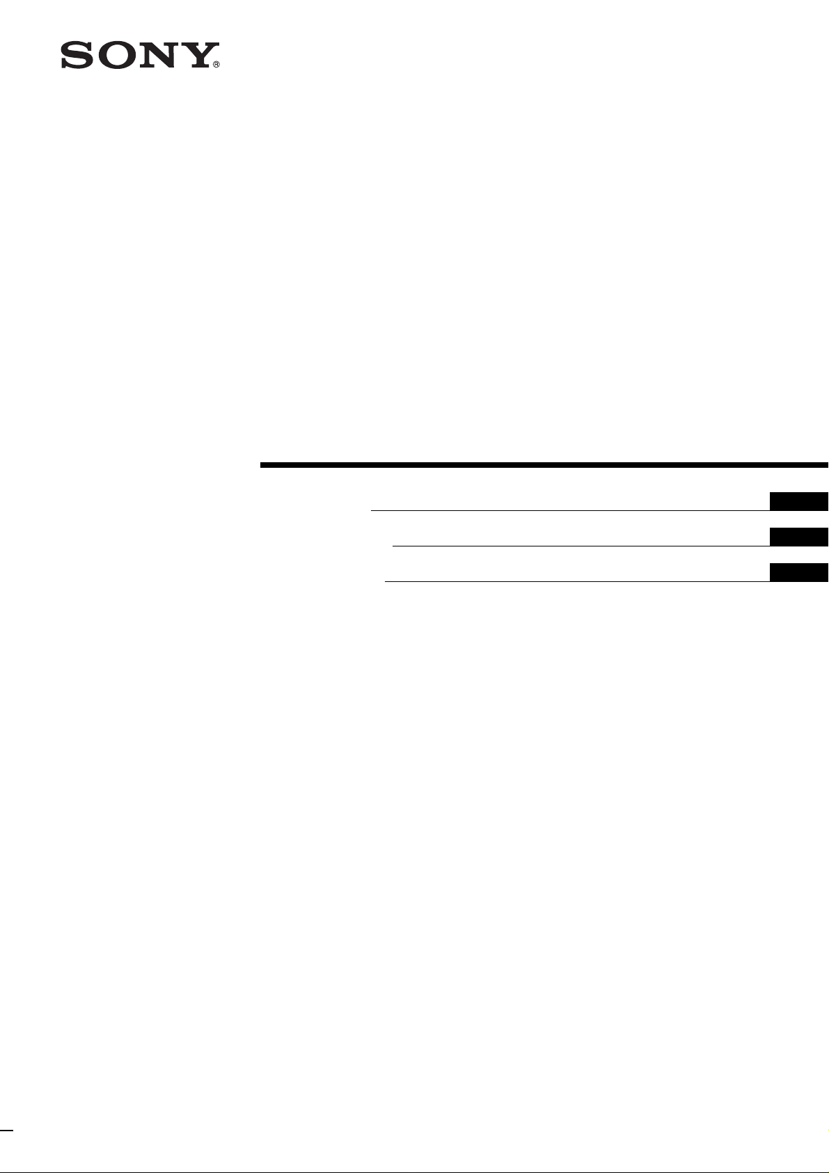
• The Display Unit may fall and cause a serious injury such as a bruise or a
fracture during an earthquake.
• If the wall on which the Wall-Mount Bracket is installed is unstable,
uneven, or not perpendicular to the floor, the unit may fall and cause
injury or property damage. The wall should be capable of supporting a
weight of at least four (4) times the Display Unit weight (KDL32XBR950:
23 kg (50 lb 11 oz) × 4 = 92 kg (202 lb 13 oz), KLV30XBR900: 20 kg (44 lb
1 oz) × 4 = 80 kg (176 lb 6 oz), and KLV-26HG2: 12 kg (26 lb 7 oz) × 4 =
48 kg (105 lb 13 oz)).
• If the installation of the Wall-Mount Bracket on the wall is not
sufficiently sturdy, the unit may fall and cause injury or property
damage.
US
English
Be sure to subcontract the installation to qualified contractors when moving
or dismounting the Wall-Mount Bracket.
If persons other than qualified contractors transport or dismount the Wall-Mount Bracket, the Display Unit may
fall and cause injury or property damage. Be sure that two or more persons carry or dismount the Wall-Mount
Bracket.
Do not spill liquid of any kind on the Display Unit.
If you allow the Display Unit to get wet, this may result in a fire or an electric shock.
Do not remove bolts, etc., after mounting the Display Unit.
If you do so, the Display Unit may fall.
Do not disassemble or make alterations to the parts of the Wall-Mount
Bracket.
If you do so, the Wall-Mount Bracket may fall and cause injury or property
damage.
Do not mount any equipment other than the specified product.
This Wall-Mount Bracket is designed for use with the specified product. If you mount equipment other than the
specified product, it may fall and cause injury or property damage.
3 (US)
Page 4
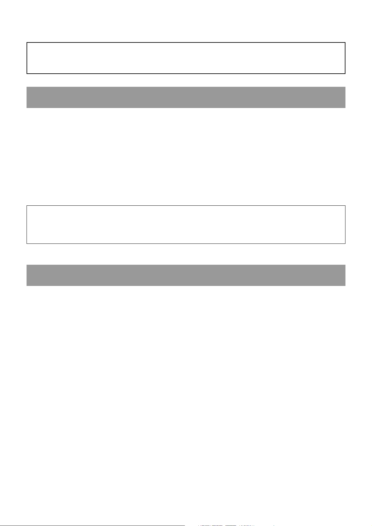
Do not block the ventilating holes on the Display Unit.
If you block the ventilating holes on the Display Unit by covering the top of
the Display Unit with a cloth or the like, the Display Unit may become
overheated and this may cause a fire.
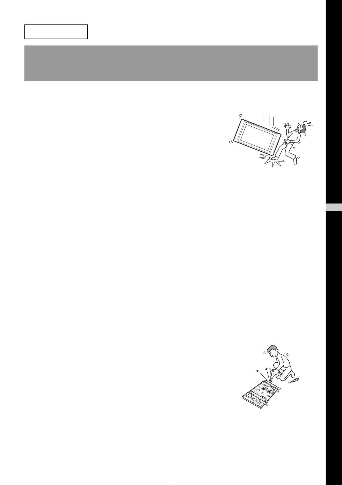
Do not apply any load other than the Display Unit on the Wall-Mount
Bracket.
If you do so, the Display Unit may fall and cause injury or property
damage.
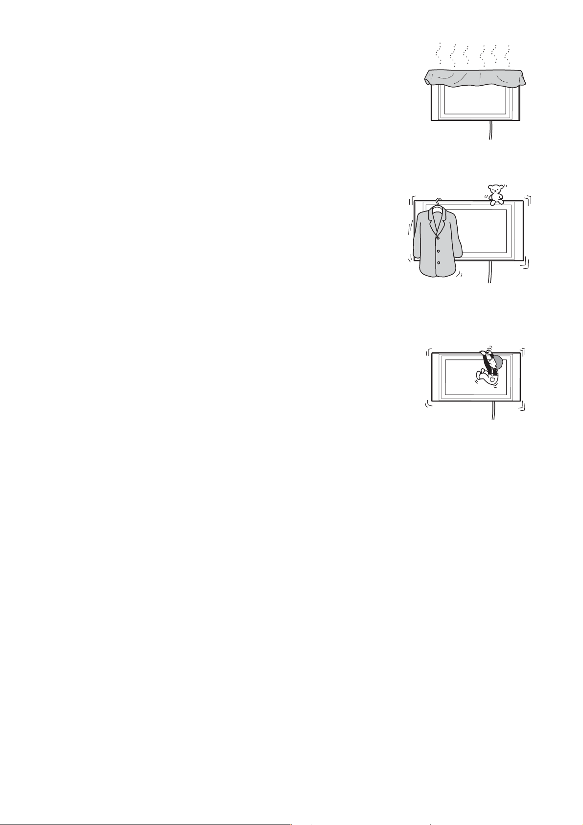
Do not lean on or hang from the Display Unit.
The Display Unit may fall and the user may be caught under the weight of
the unit and suffer serious injury.
To prevent a fire or an electric shock, do not expose the Display Unit to rain
or moisture.
If you allow the Display Unit to get wet, this may result in a fire or an electric shock.
Never place the Display Unit in hot, humid or excessively dusty places. Do not
install the Display Unit where it may be exposed to mechanical vibrations.
If you do so, this may cause a fire or an electric shock.
Keep flammable objects or open flames (e.g. candles) away from the Display
Unit.
To prevent a fire, keep flammable objects or open flames (e.g. candles) away from the Display Unit.
4 (US)
Page 5
CAUTION
If the following precautions are not observed, there is a possibility of injury or property damage.
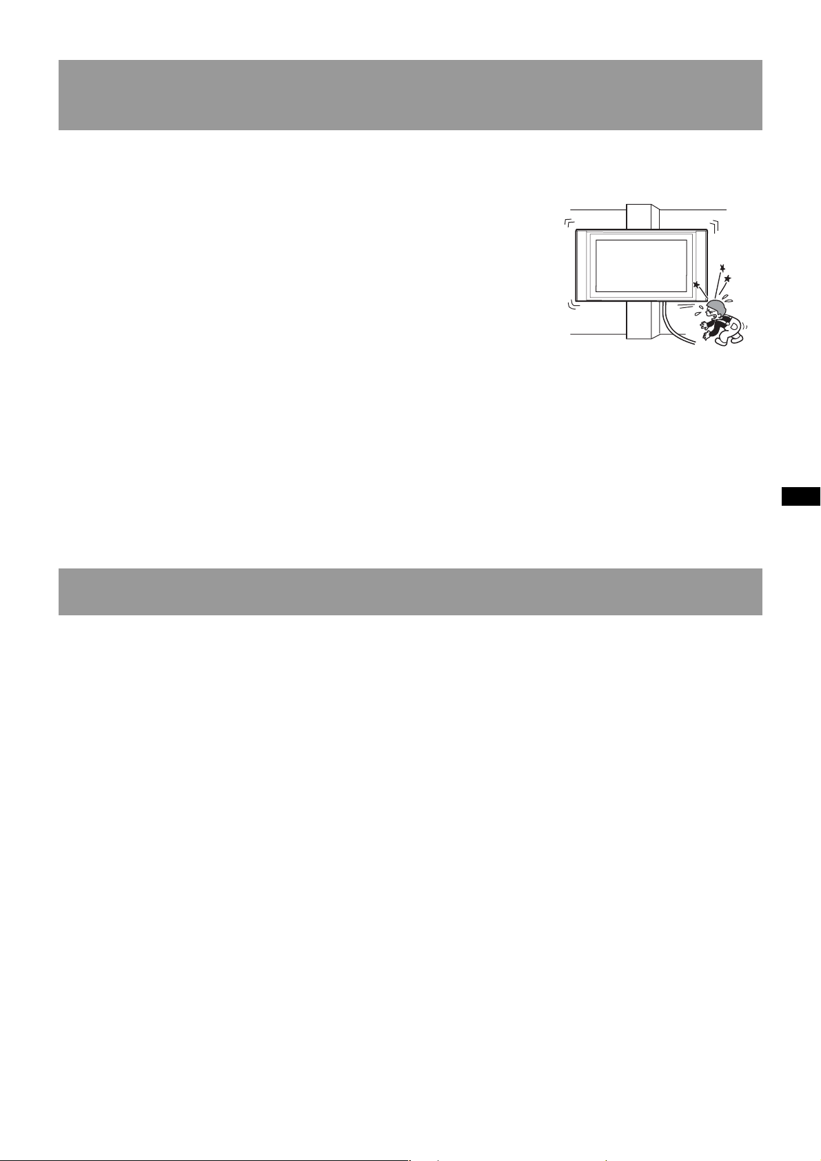
Do not install the Wall-Mount Bracket on wall surfaces where the corners or
the sides of Display Unit would protrude away from the wall surface.
Do not install the Wall-Mount Bracket on wall surfaces such as a pillar,
where the corners or the sides of Display Unit would protrude away from
the wall surface. If a person or object happens to hit the protruded corner
or side of the Display Unit, this may cause injury or property damage.
Do not handle the product with excessive force during cleaning or
maintenance.
Do not apply excessive force on the topside of the Display Unit.
If you do so, this may cause injury or property damage by causing the Display Unit to fall.
Do not install the Display Unit over or under an air-conditioner.
If you do so, the Display Unit may be exposed to air currents from the air-conditioner. This may result in a
malfunction of the Display Unit.
Precautions
• If you use the Display Unit installed on the Wall-Mount Bracket for a long time, the wall behind or above the
Display Unit may become discolored or the wallpaper may come unstuck, depending on the material of the wall.
If the Wall-Mount Bracket is removed after installing them on the wall, the screw holes are left.
• If you have routed 300 ohm feeder cables behind the wall, we recommend that you change them to 75 ohm
coaxial cables.
If it is necessary to continue to use 300 ohm feeder cables, be sure to confirm that sufficient space is available
between the Display Unit and the feeder cables behind the wall before starting the installation.
Consult your contractor on an appropriate installation location where the Display Unit suffers no radio noise
before starting the installation.
5 (US)
Page 6
Install the Wall-Mount Bracket
For Sony Dealers
WARNING To Customers
Sufficient expertise is required for installing this product. Be sure to subcontract the installation to Sony dealers
or contractors and pay adequate attention to safety during the installation.
To Sony Dealers
The following instructions are for Sony Dealers only. Be sure to read the following safety precautions and pay
adequate attention to safety during the installation, maintenance and checking of this product.
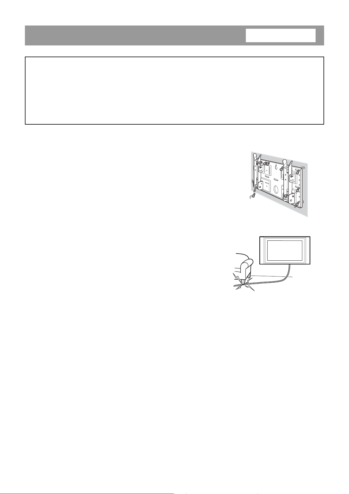
Be sure to install the Wall-Mount Bracket securely to the wall following the
instructions in this instruction manual.
If any of the screws are loose or fall out, the Wall-Mount Bracket may fall
and cause injury or property damage. Be sure to use the screws appropriate
for the material of the wall and install the unit securely, using five or more
M6 or the equivalent screws.
Do not allow the Power Cord or the Display Cable to be pinched.
If the Power Cord or the Display Cable is pinched between the unit and the
wall or is bent or twisted by force, the metallic part of the cord or cable may
be exposed and cause a short circuit or a break in the cord or cable. This
may cause a fire or an electric shock.
Be sure to use the supplied screws and attachment parts properly following
the instructions given in this instruction manual. If you use substitute items,
the Display Unit may fall, and cause bodily injury to someone or damage to
the Display Unit.
Be sure to assemble the bracket properly following the instructed procedure
explained in this instruction manual.
If any of the screws are loose or fall out, the Display Unit may fall, and cause bodily injury to someone or damage
to the Display Unit.
Be sure to tighten the bolts and screws securely in the designated position.-
If you fail to do so, the Display Unit may fall, and cause bodily injury to someone or damage to the Display Unit.
Be careful not to subject the Display Unit to shock during installation.
If the Display Unit is exposed to shock, it may fall or break apart. This may cause injury.
6 (US)
Page 7
Be sure to install the Display Unit on a wall that is both perpendicular and
flat.
If you fail to do so, the Display Unit may fall and cause injury.
After proper installation of the Display Unit, secure the cables properly.
If people or objects get tangled in the cables, this may result in injury.
Be careful not to hurt your hands or fingers during the installation.
Be careful not to hurt your hands or fingers when installing the Wall-Mount Bracket or the Display Unit.
The screws needed to secure the Wall-Mount Bracket to the wall are not
supplied.
Use the appropriate screws for the wall material and structure when mounting the Wall-Mount Bracket.
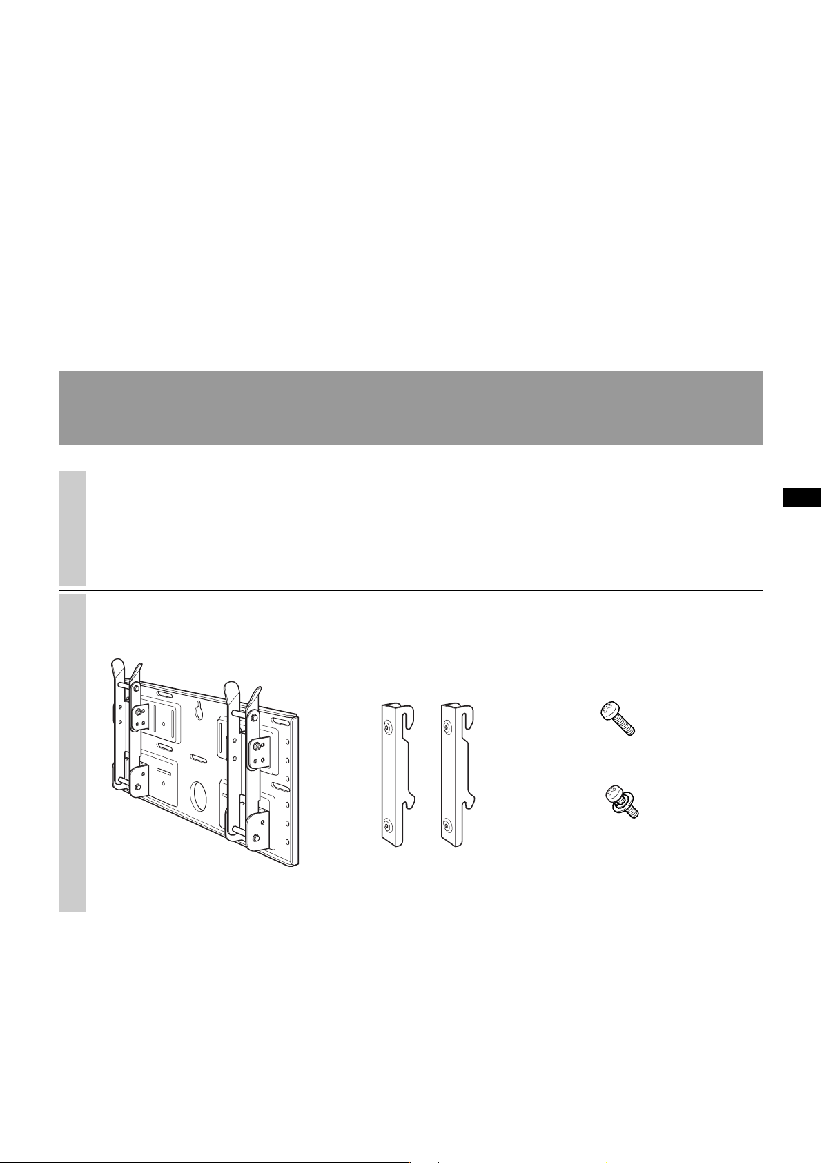
Step 1: Check to see that you have all the items
necessary for installation
1
2
Prepare five or more M6 or
equivalent screws (not supplied) and
a screwdriver. Select screws suitable
for the material of the wall.
Unpack the carton and check to see
that all the following items are
included.
Screws (+B5 × L12) (2)
Screws (+PSW5 × L16) (4)
(For the KLV-26HG2)
Plate Unit (1) Mounting Hook Unit (2)
7 (US)
Page 8
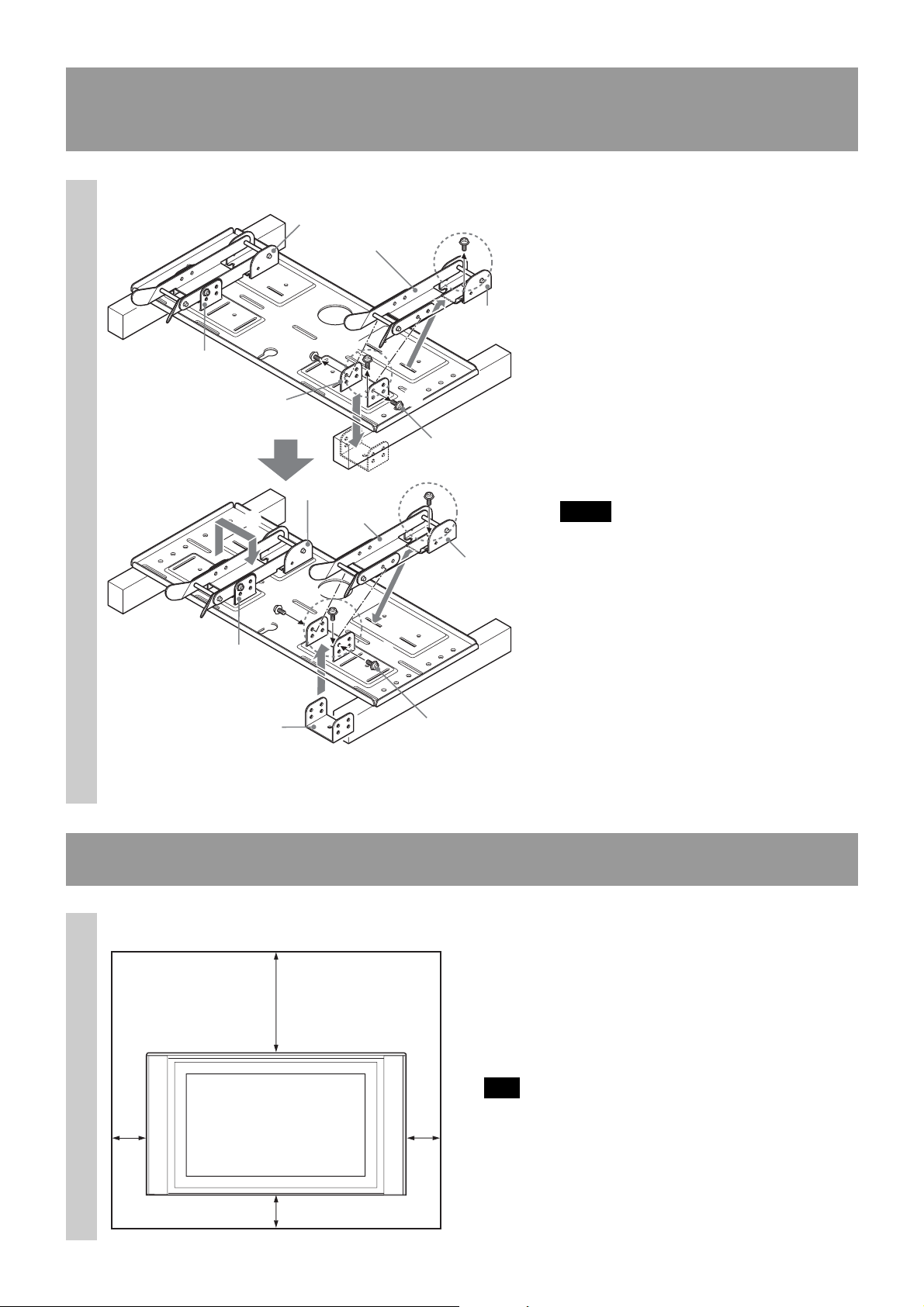
Step 2: Adjust the position of the arm bases
(For the KLV-26HG2 only)
If you are going to install a KDL32XBR950
1
Arm base A
Arm base A
3
5
Arm base B
1
Arm base B
2
Arm
4
Arm
2
Arm base B
1
Tilt adjuster
4
Arm base B
3
or a KLV30XBR900, skip Step 2 and go to
Step 3.
1Remove the four (two for each arm
bases) tilt adjusters .
2Remove the four screws that secure the
arm bases to the Plate Unit.
3Remove the arm bases A and put them
in the slots facing inward. Put both arms
and the arm bases B on the arm bases
A.
4Secure the arm bases to the Plate Unit
using the four screws removed in 2.
5Secure the arms to the arm bases using
the four tilt adjusters removed in 1.
Notes
• If you are installing a display other than
the KLV-26HG2, skip Step 2.
•When using an electric screwdriver to
tighten the screws, the torque must be
approx. 2 N•m.
Arm base A
3
Arm base A
5
Tilt adjuster
Step 3: Decide on the location for installation
Unit: mm (inches)
1
100
(3
)
16
/
13
300
(11
100
15
⁄16)
15
(3
⁄16)
Leave spaces around the display. At
least the amount of space shown in
the diagram should be left between
the display and a ceiling or raised
portions of the wall.
Tip
Refer to the table (9 (US)) for the display installation
dimensions.
8 (US)
100
)
16
⁄
15
(3
Page 9

Display installation dimensions table
Display
Model
KLV30XBR900
KDL32XBR950
KLV-26HG2
A
/16)
9
(
14
/32)
9
(8
210
D
B
B
E
500
(19 11/16)
Display Dimensions
ABCDE
971 524 93 68 268
(38 7/32) (20 5/8) (3 21/32) (2 11/16) (10 9/16) (8 1/8) (6 9/16) (13 27/32) (80 kg
1,052 569 97 31 291
(41 13/32) (22 13/32) (3 13/16) (1 7/32) (11 15/32) (8 5/8) (8 27/32) (13 11/32) (92 kg
790 430 118 65 215
(31 3/32) (16 15/16) (4 21/32) (2 9/16) (8 15/32) (8 21/32) (5 3/32) (11 27/32) (48 kg
Unit: mm (inches)
Length for each mounting angle
Mounting angle (α°)
0°
5°
10°
15°
20°
0°
5°
10°
15°
20°
0°
5°
10°
15°
20°
FGH (×4)*
147 188 336
(5 25/32) (7 13/32) (13 7/32)
177 179 345
(6 31/32) (7 1/16) (13 19/32) 20 kg
206 167 352
234 152 258
(9 7/32) (5 31/32) (10 5/32)
260 135 363
(10 1/4) (5 5/16) (14 9/32)
151 247 322
(5 15/16) (9 23/32) (12 11/16)
186 237 331
(7 5/16) (9 11/32) (13 1/32) 23 kg
219 225 339
252 209 345
(9 29/32) (8 7/32) (13 19/32)
282 190 350
(11 3/32) (7 15/32) (13 25/32)
167 150 280
(6 9/16) (5 29/32) (11 1/32)
194 139 291
(7 5/8) (5 15/32) (11 15/32) 12 kg
220 129 301
244 122 310
(9 19/32) (4 13/16) (12 7/32)
266 113 318
(10 15/32) (4 7/16) (12 17/32)
F
C
Unit: mm (inches)
(50 lb 11 oz)
(202 lb 13 oz))
(105 lb 13 oz))
G
H
Weight
(44 lb 1 oz)
(176 lb 6 oz))
(26 lb 7 oz)
* The wall must be strong enough to support at least four times the weight of the display that you are installing.
9 (US)
Page 10
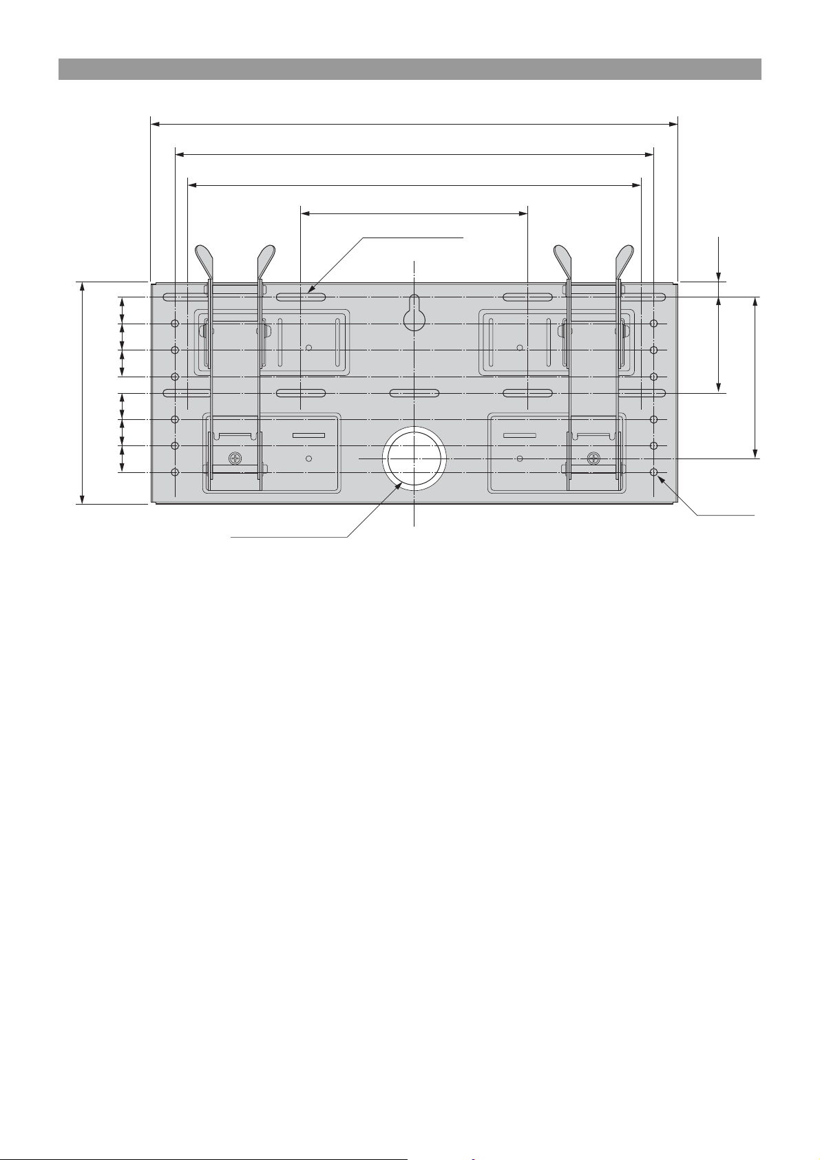
Wall installation diagram
)
32
/
25
31
(
)
32
/
25
31
(
)
32
/
25
25
25
25
31
(
)
32
/
31
(
)
32
/
31
(
)
32
/
31
(
)
32
/
9
210 (8
500 (19 11/16)
454 (17 7/8)
430 (16
215 (8
9
/
9-7×40 (
32
Oblong hole
15
/16)
15
/32)
× 1 9/16)
Unit: mm (inches)
)
16
/
9
) 14 (
32
/
19
)
16
/
91 (3
13
148 (5
12-φ7 (φ
3
φ60 (2
/8)
Hole for cable routing
Refer to the diagram above for wall installation requirements (when reinforcing the wall or routing cables in the
wall).
WARNING
The wall must be strong enough to support at least four times the weight of the display that you are installing
(9 (US)). Make sure the wall has sufficient strength. Reinforce the wall if necessary.
9
/32)
10 (US)
Page 11
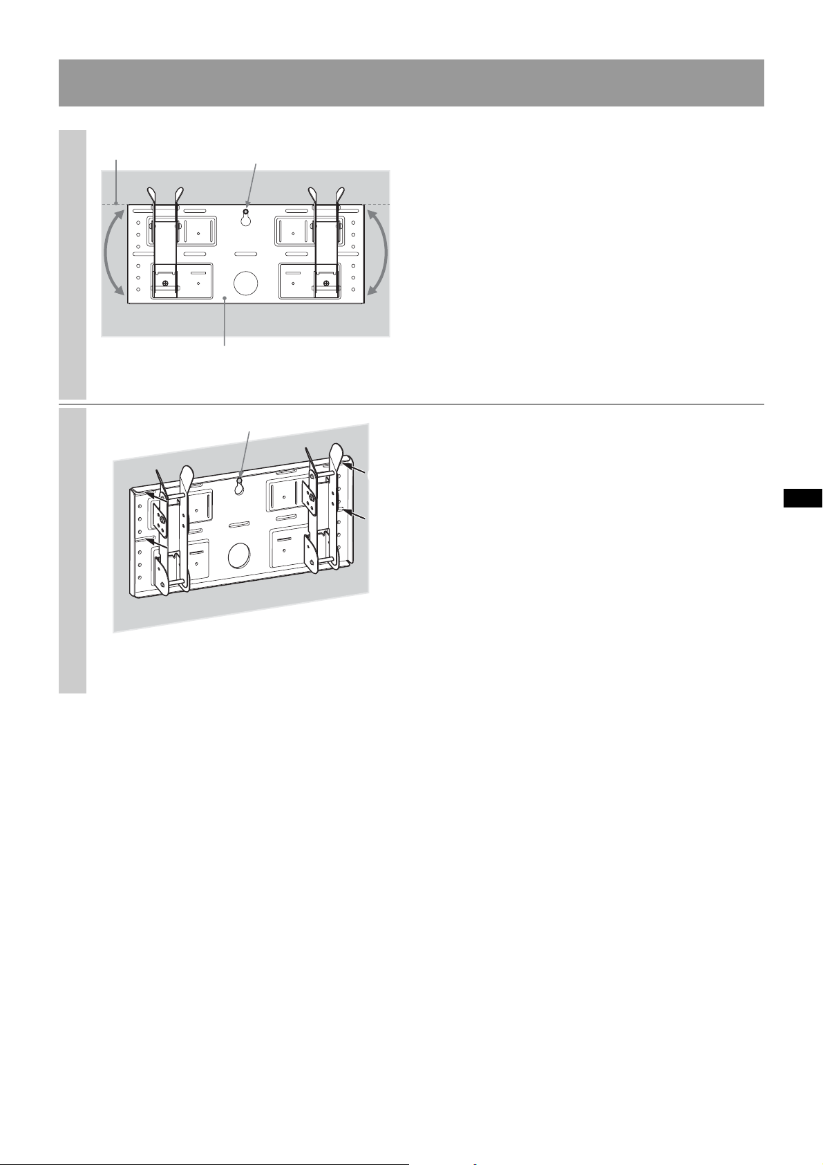
Step 4: Install the Plate Unit on the wall
Align the Plate Unit.
1
2
Hole used for temporarily
attaching the Plate Unit
Plate Unit
2
1
Temporarily secure the Plate Unit to
the wall using a screw. Align the
Plate Unit to make it level with the
floor.
WARNING
• The screw used in this procedure is not supplied
with the unit.
• Select a screw suitable for the material and the
structure of the wall.
Secure the Plate Unit to the wall
using four or more M6 or equivalent
screws (not supplied).
1Tighten the screws firmly so that the Plate Unit can
support the weight of the display.
2Tighten the screw used in 1.
WARNING
The wall must be strong enough to support at least
four times the weight of the display that you installing
(9 (US)). Make sure the wall has sufficient strength.
Reinforce the wall if necessary.
11 (US)
Page 12
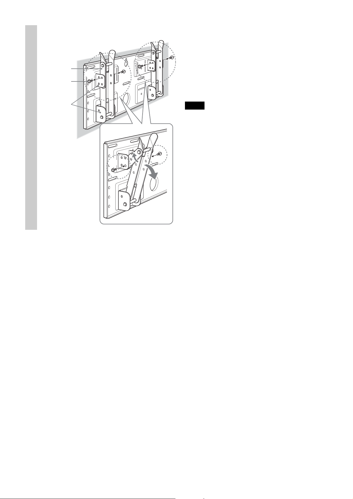
3
Adjust the tilt of the arms.
If you want to install the display vertically, flush with
the wall (0°), skip 1 and 2 below. Check that the
arms are securely attached to the Plate Unit.
Arm
Tilt adjuster
Arm bases
A and B
1
2
1Remove all four tilt adjusters.
2Put them into the screw holes corresponding to the
desired angle (5°, 10°, 15°, or 20°) and tighten them
firmly.
Notes
• The angle of the left and right arms must be the
same.
• Be careful not to catch your fingers when adjusting
the angle of the arms.
•When using an electric screwdriver to tighten the
screws, the torque must be approx. 2 N•m.
• Check that the arm bases are securely attached to
the Plate Unit.
12 (US)
Page 13
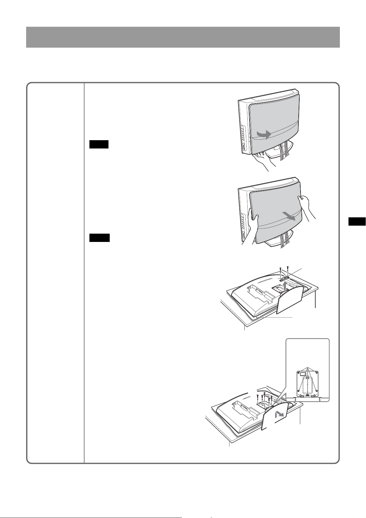
Step 5: Detach the display from the Tabletop Stand
The procedure differs depending on the display model. Apply the procedure
appropriate for the display you are installing.
KLV-26HG2
1Pull the lower corner (either right or
left ) of the rear cover. Then pull the
other lower corner.
2Hold the rear cover with both hands
and pull it towards you. The rear
cover will separate from the display.
Note
Lay the display face down on a soft cloth
before going to 3.
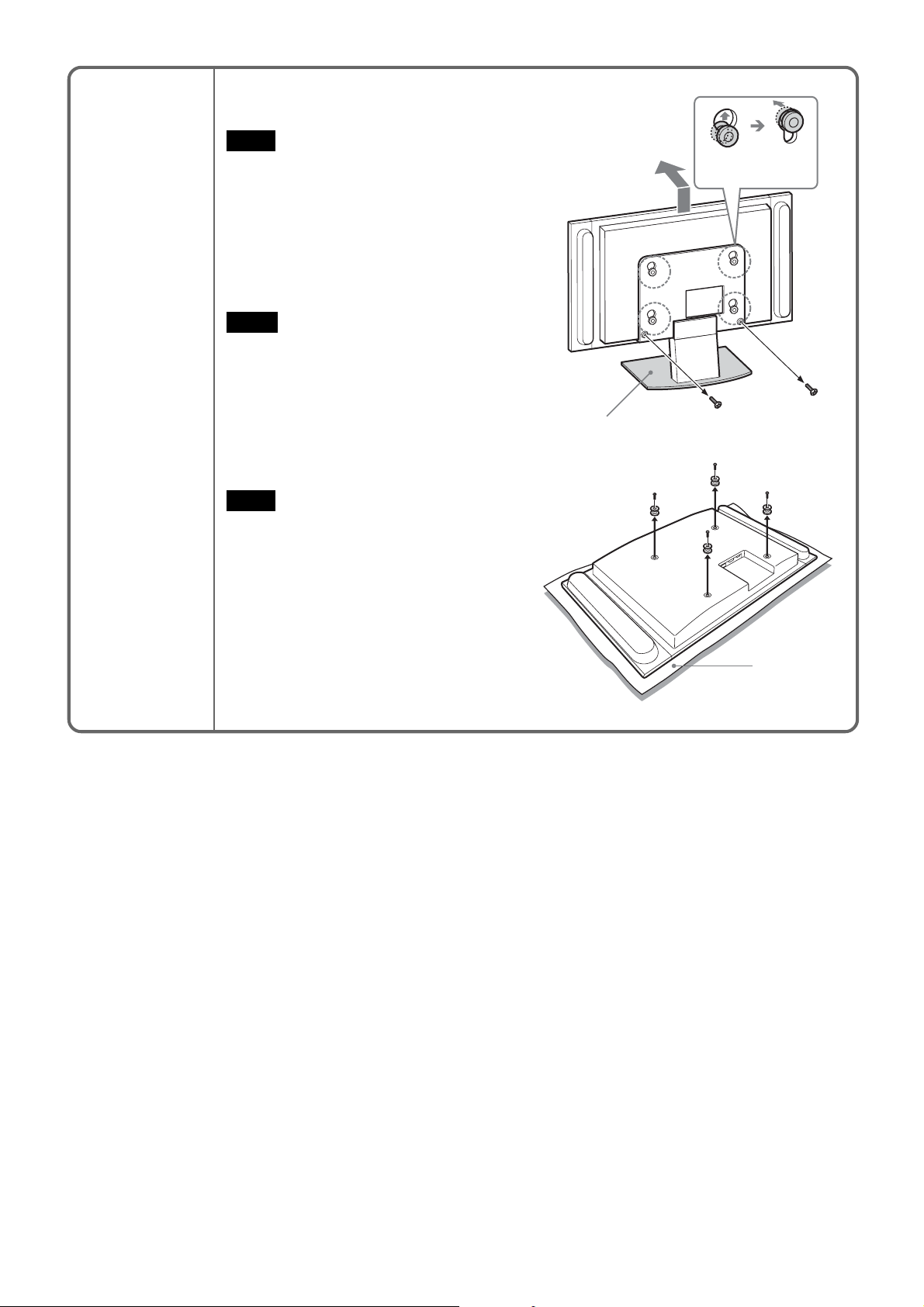
3Remove the two small screws from
the clip. Detach the clip from the
Tabletop Stand.
4Remove the five screws from the
Tabletop Stand.
5Lift up the Stand slightly, then pull it
towards you. The Stand will separate
from the display.
Notes
• Lay the display face down on a stable
and level surface, leaving the base of
the Stand sticking out in the air.
Putting the display face and the base
of the Stand on the same level surface
makes the Display Unit inclined, thus
unstable, causing any danger.
•When removing the Tabletop Stand,
hold it firmly.
1
2
3
Clip
Soft cloth
4
5
Screws
removed in 4
13 (US)
Page 14
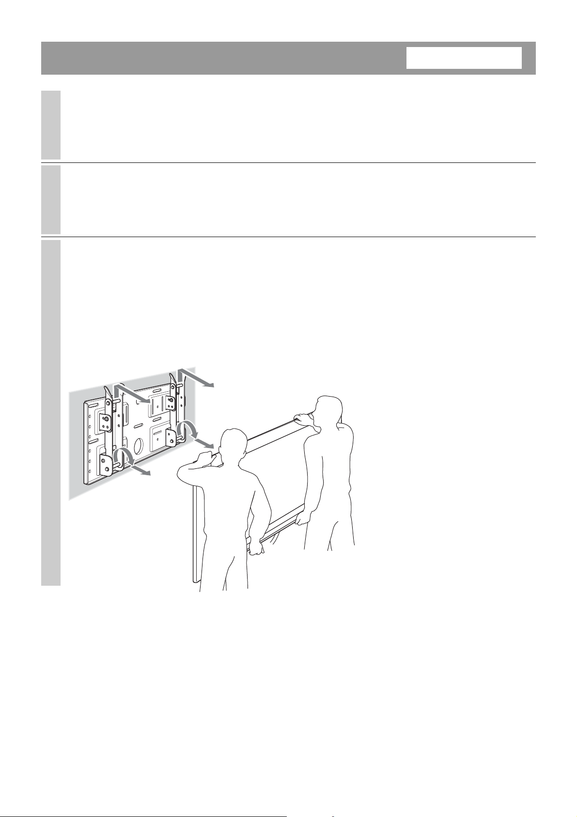
KLV30XBR900
1Remove the two screws from the Tabletop
Stand.
Note
Do not lay the display down when carrying
out the procedure.
2Holding down the base of the Stand, lift
up the display slightly, then move it away
from the Stand. The display will separate
from the Stand. At least two persons must
hold and carry the display.
Notes
• At least two persons must work together
on this procedure.
•When lifting up the display, hold the base
of the Stand so that it is not lifted along
with the display.
3Remove the four hooks on the rear cover
of the display.
Lift up and carry
forward.
2
1
Base of the Stand
Note
Lay the display face down on a soft cloth.
3
Soft cloth
14 (US)
Page 15
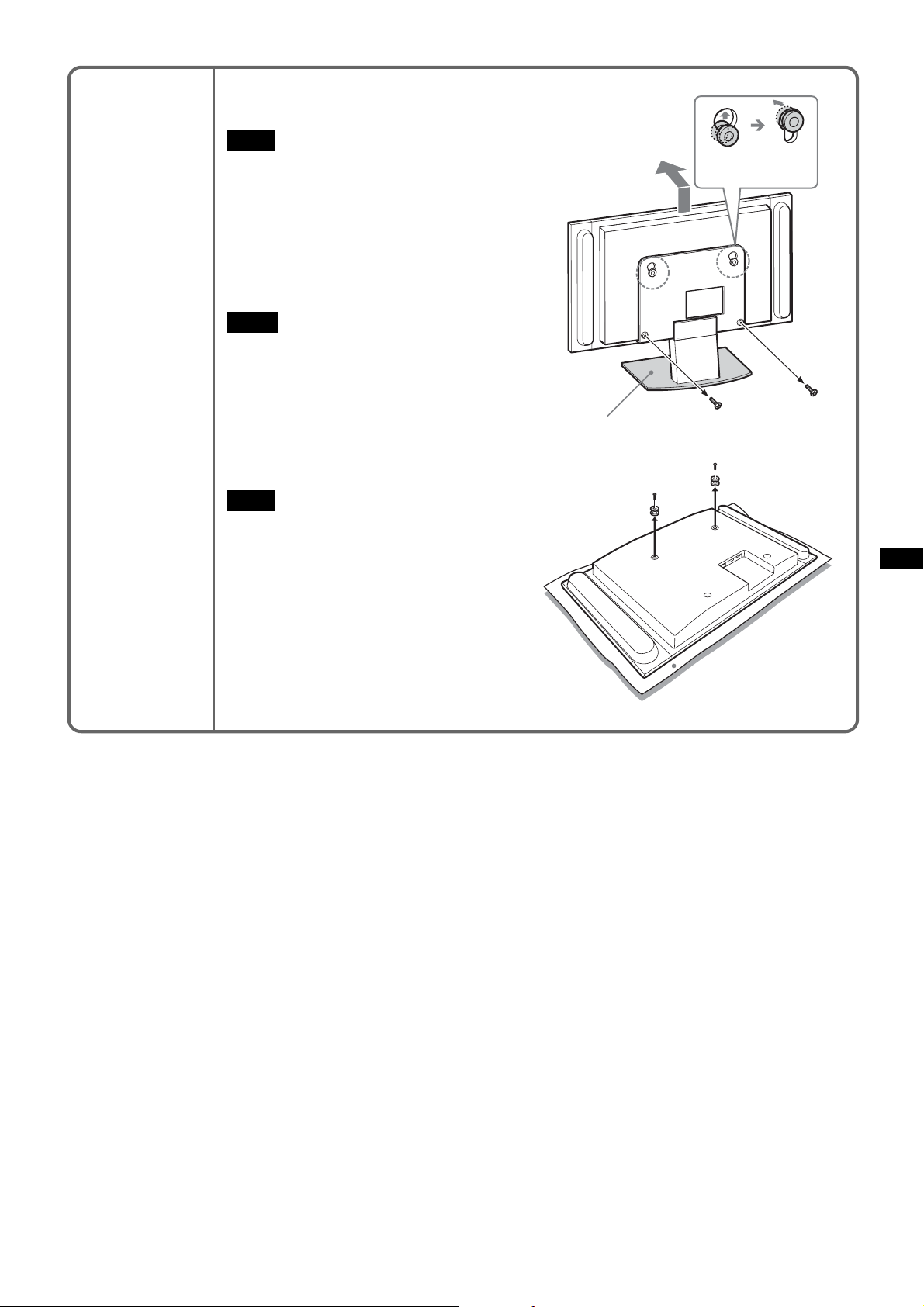
KDL32XBR950
1Remove the two screws from the Tabletop
Stand.
Note
Do not lay the display down when carrying
out the procedure.
2Holding down the base of the Stand, lift
up the display slightly, then move it away
from the Stand. The display will separate
from the Stand. At least two persons must
hold and carry the display.
Notes
• At least two persons must work together
on this procedure.
•When lifting up the display, hold the base
of the Stand so that it is not lifted along
with the display.
3Remove the two hooks on the rear cover
of the display.
Lift up and carry
forward.
2
1
Base of the Stand
Note
Lay the display face down on a soft cloth.
3
Soft cloth
15 (US)
Page 16
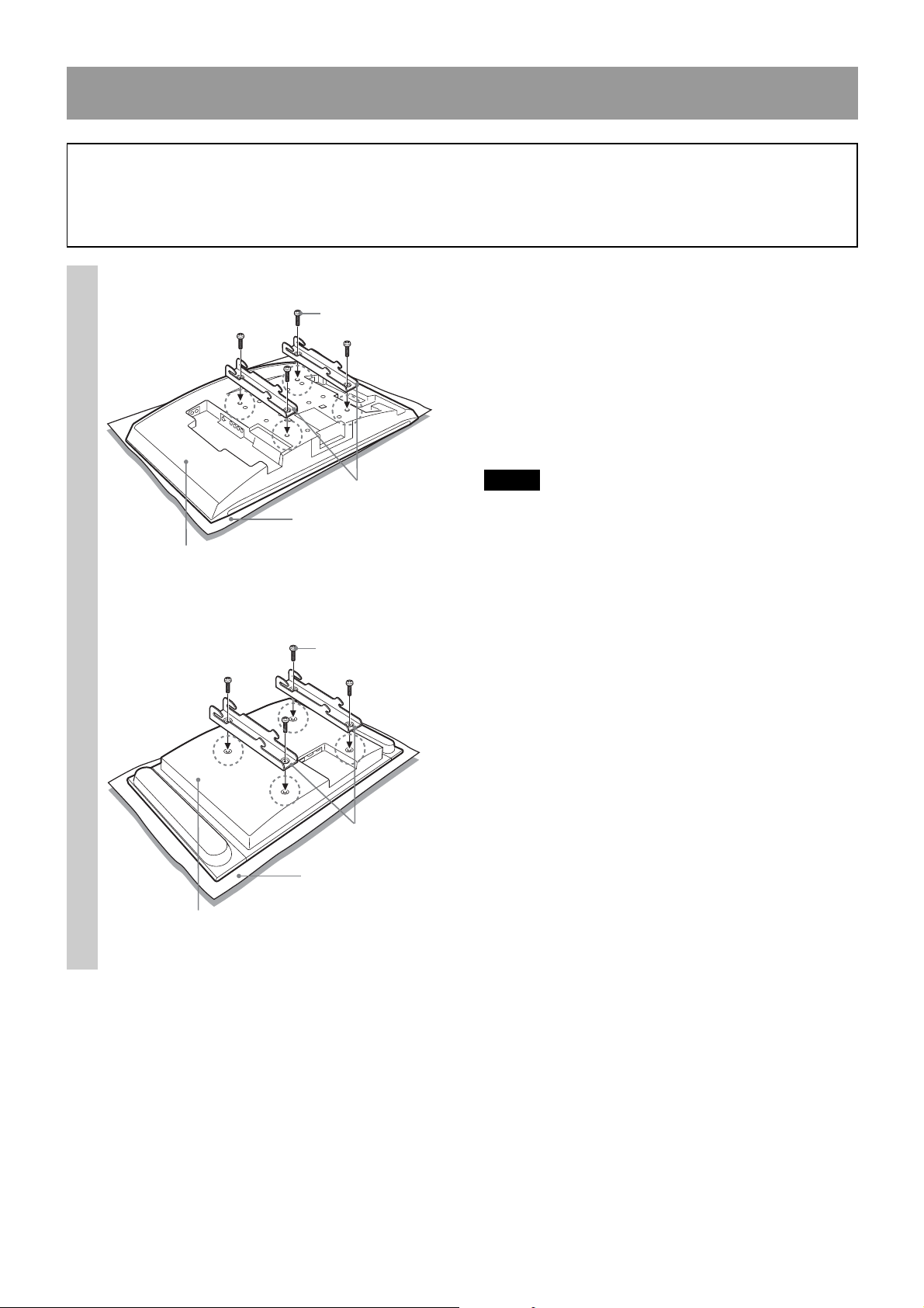
Step 6: Install the display on the Plate Unit
WARNING
Do not connect the power cord to a wall outlet before the installation is completed. If the power cord is
pinched, a short circuit may occur, causing an electric shock.
Be careful not to stumble over the cables or the display.
KLV-26HG2
1
Rear of the display
KDL32XBR950/KLV30XBR900
The supplied screws
(+PSW5 × L16)
Mounting Hook Units
Soft cloth
The screws removed
in Step 5
Align the holes on the Mounting
Hook Units with the corresponding
holes on the rear of the display.
Secure them to the display using
four screws.
For the KLV-26HG2, use the screws supplied (+PSW5
× L16). For the KDL32XBR950 and the KLV30XBR900,
use the screws you removed in Step 5.
Notes
• Lay the display face down on a soft cloth.
•When using an electric screwdriver to tighten the
screws, the torque must be approx. 2 N•m.
16 (US)
Mounting Hook Units
Soft cloth
Rear of the display
Page 17

2
Hole for cable routing
Connect the supplied power cord
and cables.
Connect the power cord and cables to the
corresponding jacks on the rear of the display. For
details on the cable connection, see the Operating
Instructions for your display.
When routing cables in a wall, pass the cables through
a hole made in the wall for cable routing (10 (US)).
Notes
•You cannot connect the cables to the display after
installing it on the Plate Unit.
• Subcontract the cable routing in the wall to
qualified contractors.
17 (US)
Page 18
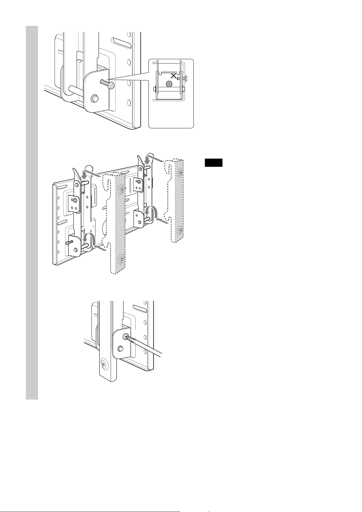
3
1
Do not push
the screws in
too far.
Mount the display on the Plate
Unit.
1To lock the arms temporarily, put the two
securing screws (+B5 × L12, supplied) in the
holes on the arm bases B from the outside.
2Hang the upper hooks of the Mounting Hook
Units on the upper shafts of the arms.
3Place the lower hooks of the Mounting Hook
Units on the lower shafts of the arms.
4Pushing the display towards the Plate Unit,
lift it up slowly and hang the lower hooks of
the arms onto the lower shafts.
5Check to make sure that all eight hooks are
properly hung on the corresponding shafts.
6Tighten the securing screws attached in 1.
2
Note
If you push the securing screws into the holes
too far (1), the tips of the screws will get in the
way when you hang the lower hooks on the
shafts (4).
4
3
6
18 (US)
Page 19
Check to make sure all the procedures have been
properly completed
Check the following.
• All eight hooks are securely hung on the corresponding shafts.
• The cables are neither twisted nor pinched.
• The two securing screws are securely tightened.
WARNING
If not properly installed, the unit may fall, causing injury to persons or damage to the unit itself. If the cables
are not properly routed, a short circuit may occur, causing a fire or an electric shock. For your safety, be sure to
check that all the procedures have been properly carried out.
19 (US)
Page 20
To dismount the display
1
2
3
For Sony Dealers
Unplug the power cord from the
wall outlet.
Remove the two securing screws.
Two or more persons should lift up
the display and dismount it from the
Plate Unit.
WARNING
• At least two persons must hold and carry the
display.
•When dismounting the display, be careful not to
catch the cables.
•When dismounting the display, be careful of your
hands and fingers.
20 (US)
Page 21

Specifications
Unit: mm (inches)
Mass: 3.4 kg (7 lb 8 oz)
500 (19 11⁄16)
)
32
⁄
9
210 (8
)
32
⁄
21
245 (9
40
(1 9⁄16)
)
8
⁄
5
270 (10
Design and specifications are subject to change without notice.
21 (US)
Page 22

Nous vous remercions d’avoir fait l’acquisition de ce produit.
A l’attention des clients
Une certaine expérience est requise pour installer ce produit. Confiez l’installation à des revendeurs Sony ou à
des professionnels et portez une attention particulière à la sécurité au cours de l’installation.
AVERTISSEMENT
Le non-respect des règles de sécurité et l’utilisation incorrecte de ce produit peut provoquer un incendie ou des
blessures graves.
Ce mode d’emploi indique les précautions essentielles pour éviter tout accident et garantir une bonne utilisation
du produit. Lisez attentivement ce mode d’emploi et veillez à utiliser ce produit correctement. Conservez ce mode
d’emploi pour toute référence ultérieure.
A l’attention des revendeurs Sony
Une certaine expérience est requise pour installer ce produit. Lisez ce mode d’emploi attentivement afin de
procéder à l’installation en toute sécurité. Nous ne sommes nullement responsables de tout dommage ou blessure
consécutif(ve) à une mauvaise utilisation ou à une installation incorrecte. Une fois l’installation effectuée, remettez
ce manuel d’installation aux clients.
Ce support de fixation mural est conçu par Sony pour être utilisé avec le produit spécifié. N’utilisez pas ce
support avec un autre appareil que le produit suivant.
Produits spécifiés : LCD Color TV (KDL32XBR950/KLV30XBR900/KLV-26HG2)
Sécurité
Les produits Sony sont conçus pour vous offrir le maximum de sécurité.
Toutefois si ce produit est utilisé de façon incorrecte, il peut provoquer des blessures graves en cas d’incendie,
d’électrocution ou de chute de l’appareil. Veillez à observer les précautions de sécurité préconisées pour éviter de
tels accidents.
2 (FR)
Page 23

A l’attention des clients
AVERTISSEMENT
Le non-respect des précautions suivantes peut entraîner la mort ou des blessures graves en cas
d’incendie, d’électrocution ou d’explosion.
Confiez l’installation à des professionnels qualifiés et tenez les enfants à
l’écart pendant la durée de l’installation.
Si des personnes autres que des professionnels qualifiés installent le
support de fixation mural, les accidents suivants peuvent se produire :
•L’écran peut tomber et causer des blessures graves comme des
hématomes ou des fractures en cas de tremblement de terre.
• Si le mur sur lequel le support de fixation mural est fixé est instable,
inégal ou non perpendiculaire au sol, l’appareil risque de tomber et de
vous blesser ou de provoquer des dommages matériels. Le mur doit
pouvoir supporter un poids équivalent à quatre (4) fois le poids de
l’écran (KDL32XBR950 : 23 kg (50 lb 11 oz) × 4 = 92 kg (202 lb 13 oz),
KLV30XBR900 : 20 kg (44 lb 1 oz) × 4 = 80 kg (176 lb 6 oz), KLV-26HG2 :
12 kg (26 lb 7 oz) × 4 = 48 kg (105 lb 13 oz)).
• Si l’installation du support de fixation mural n’est pas assez solide,
l’appareil risque de tomber et de vous blesser ou de provoquer des
dommages matériels.
Confiez l’installation à des professionnels qualifiés lorsque vous déplacez ou
démontez le support de fixation mural.
Si des personnes autres que des professionnels qualifiés transportent ou démontent le support de fixation mural,
l’écran peut tomber et provoquer des blessures ou des dommages matériels. Deux personnes au moins doivent
porter ou démonter le support de fixation mural.
Ne renversez aucun liquide sur l’écran.
Si ce dernier venait à être mouillé, il risquerait de provoquer un incendie ou une électrocution.
Ne retirez pas de boulons, etc., après l’installation de l’écran.
Dans le cas contraire, l’écran risque de tomber.
Ne démontez pas ou n’apportez pas de modifications aux pièces du support
de fixation mural.
Dans le cas contraire, le support risque de tomber et de vous blesser ou de
provoquer des dommages matériels.
FR
Français
N’utilisez pas d’autre appareil que le produit spécifié.
Ce support de fixation mural est conçu pour être utilisé avec le produit spécifié. Si vous installez un autre appareil
que le produit spécifié, il risque de tomber et de vous blesser ou de provoquer des dommages matériels.
3 (FR)
Page 24

Ne bloquez pas les orifices de ventilation de l’écran.
Si vous bloquez les orifices de ventilation de l’écran en couvrant la partie
supérieure de l’écran avec un tissu ou autre, l’écran peut surchauffer et ceci
risque de provoquer un incendie.
N’appliquez aucune charge autre que l’écran sur le support de fixation mural.
Dans le cas contraire, l’écran risque de tomber et de vous blesser ou de
provoquer des dommages matériels.
Ne vous appuyez pas sur l’écran ou ne vous pendez pas après.
L’écran risquerait de tomber et l’utilisateur serait coincé par le poids de
l’appareil, il en résulterait des blessures graves.
Pour éviter tout risque d’incendie ou d’électrocution, n’exposez pas l’écran à
la pluie ou à l’humidité.
Si l’écran venait à être mouillé, il risquerait de déclencher un incendie ou une électrocution.
Ne placez jamais l’écran dans des endroits chauds, humides ou extrêmement
poussiéreux. N’installez pas l’écran à des endroits où il serait soumis à des
vibrations mécaniques.
Dans le cas contraire, ceci risque de provoquer un incendie ou un risque d’électrocution.
Conservez les objets inflammables ou les flammes nues (ex : bougies) à l’écart
de l’écran.
Pour éviter tout risque d’incendie, gardez les objets inflammables ou les flammes nues (ex : bougies) à l’écart de
l’écran.
4 (FR)
Page 25

ATTENTION
Le non-respect des précautions suivantes risque de provoquer des blessures ou des dommages matériels.
N’installez pas le support de fixation mural sur des surfaces murales où les
coins ou les côtés de l’écran dépasseraient.
N’installez pas le support de fixation mural sur des surfaces murales, telles
qu’un pilier où les coins ou les côtés de l’écran dépasseraient de la surface.
Si une personne ou un objet venait à heurter le coin ou les côtés de l’écran,
ceci risquerait de provoquer une blessure ou d’endommager appareil.
N’exercez aucune force excessive sur le produit en cours de nettoyage ou
d’entretien.
N’exercez pas une force excessive sur la face supérieure de l’écran.
Dans le cas contraire, l’écran risque de tomber et de vous blesser ou entraîner des dommages matériels.
N’installez pas l’écran sur ou sous un climatiseur.
Dans le cas contraire, l’écran risque d’être exposé aux courants d’air du climatiseur. Ceci risquerait de provoquer
un dysfonctionnement de l’écran.
Précautions
• Si vous utilisez l’écran fixé au support de fixation mural pendant une longue période, le mur situé derrière ou
au-dessus de l’écran peut se décolorer ou le papier peut se décoller selon le matériau du mur. Les trous des vis
restent apparents si vous démontez le support de fixation mural après son installation.
• Si vous avez fait passer des câbles d’alimentation de 300 ohms derrière le mur, nous vous recommandons de les
remplacer par des câbles coaxiaux de 75 ohms.
Toutefois, s’il est nécessaire de continuer à utiliser des câbles d’alimentation de 300 ohms, un espace
suffisamment important doit être prévu entre l’écran et les câbles d’alimentation derrière le mur avant de
procéder à l’installation.
Avant de procéder à l’installation, consultez votre installateur sur l’emplacement où l’écran ne subira aucune
interférence radio.
5 (FR)
Page 26

Installation du support de fixation mural
revendeurs Sony
AVERTISSEMENT A l’attention des clients
A l’attention des
Une certaine expérience est requise pour installer ce produit. Confiez l’installation à des revendeurs Sony ou à
des professionnels et portez une attention particulière à la sécurité au cours de l’installation.
A l’attention des revendeurs Sony
Les instructions suivantes concernent les revendeurs Sony uniquement. Lisez attentivement les consignes de
sécurité décrites ci-dessus et accordez une attention particulière à la sécurité lors de l’installation, de l’entretien
et de la vérification de ce produit.
Veillez à installer le support de fixation mural correctement au mur en suivant
les instructions de ce mode d’emploi.
Si certaines des vis sont desserrées ou sont absentes, le support de fixation
mural peut tomber et provoquer des blessures ou des dommages matériels.
Utilisez les vis convenant au type de cloison et fixez solidement l’appareil à
l’aide des cinq vis M6 (ou davantage) ou de vis équivalentes.
Le cordon d’alimentation ou le câble de l’écran ne doivent pas être coincés.
Si le cordon d’alimentation ou le câble de l’écran est coincé entre l’appareil
et le mur ou s’il est plié ou tordu en forçant, la partie métallique du cordon
ou du câble peut être exposée et provoquer un court-circuit ou une cassure
du cordon ou du câble. Ceci risquerait de provoquer un incendie ou une
électrocution.
Veillez à utiliser les vis et les pièces de fixation fournies en suivant les
instructions de ce mode d’emploi. Si vous utilisez d’autres éléments de
fixation, l’écran risque de tomber et de vous blesser ou d’être endommagé.
Veillez à monter le support correctement en suivant la procédure décrite dans
ce mode d’emploi.
Si certaines vis sont desserrées ou sont absentes, l’écran risque de tomber et de blesser quelqu’un ou d’être
endommagé.
Veillez à serrer les boulons et les vis correctement dans la position indiquée.
Dans le cas contraire, l’écran risque de tomber et de vous blesser ou d’être endommagé.
Veillez à ne pas faire subir de chocs à l’écran pendant l’installation.
Si l’écran est soumis à des chocs, il risque de tomber ou de se casser. Ceci risquerait de vous blesser.
6 (FR)
Page 27

Veillez à installer l’écran sur un mur qui soit à la fois perpendiculaire au sol et
plat.
Dans le cas contraire, l’écran risque de tomber et de vous blesser.
Après une installation correcte de l’écran, fixez les câbles correctement.
Si des personnes ou des objets se prennent dans les câbles, ceci risque de provoquer des blessures.
Prenez garde de ne pas vous blesser aux mains ou aux doigts pendant
l’installation.
Prenez garde à ne pas vous blesser aux mains ou aux doigts lors de l’installation du support de fixation mural ou
de l’écran.
Les vis nécessaires pour fixer solidement le support de fixation mural au mur
ne sont pas fournies.
Utilisez les vis appropriées selon le matériau et la structure du mur lors du montage du support de fixation mural.
Etape 1 : Vérification des pièces requises pour
1
2
l’installation
Préparez au moins cinq vis M6 ou
équivalentes, non fournies, ainsi
qu’un tournevis. Sélectionnez des vis
convenant au type de cloison.
Ouvrez l’emballage pour vérifier
que toutes les pièces suivantes s’y
trouvent.
Vis (+B5 × L12) (2)
Plaque de fixation (1) Crochet de fixation (2)
Vis (+PSW5 × L16) (4)
(Pour le KLV-26HG2)
7 (FR)
Page 28

Etape 2 : Réglage de la position de l’embase du bras
(pour le KLV-26HG2 uniquement)
Si vous avez l’intention d’installer un
1
Embase A
Embase A
Embase A
3
5
Embase A
Embase B
1
Embase B
4
3
2
Bras
Bras
2
Embase B
1
Limiteur d’inclinaison
4
Embase B
3
5
Limiteur d’inclinaison
KDL32XBR950 ou un KLV30XBR900,
sautez l’Etape 2 et passez directement à
l’Etape 3.
1Retirez les quatre limiteurs d’inclinaison
(deux pour chaque embase du bras).
2Retirez les quatre vis qui maintiennent
les embases des bras à la plaque de
fixation.
3Retirez les embases du bras A et
introduisez-les dans les fentes vers
l’intérieur. Placez les deux bras et les
embases B sur les embases A.
4Fixez les embases de bras à la plaque de
fixation à l’aide des quatre vis retirées en
2.
5Fixez les bras aux embases à l’aide des
quatre limiteurs d’inclinaison retirés en
1.
Remarques
• Si l’écran que vous installez n’est pas le
KVL-26HG2, sautez l’Etape 2.
• Si vous utilisez un tournevis électrique
pour serrer les vis, le couple de serrage
doit être réglé à 2 N•m environ.
Etape 3 : Choix de l’emplacement d’installation
Unité : mm (pouces)
1
100
15
(3
8 (FR)
)
16
/
13
300
(11
100
15
(3
⁄16)
)
16
⁄
15
100
(3
⁄16)
Laissez un espace suffisant autour de
l’écran. Vous devez laisser au
minimum la distance indiquée dans
le schéma ci-contre entre l’écran et
le plafond ou les parties saillantes
du mur.
Conseil
Reportez-vous au tableau (9 (FR)) pour connaître les
dimensions d’installation de l’écran.
Page 29

Tableau des dimensions pour l’installation de l’écran
Modèle
d’écran
KLV30XBR900
KDL32XBR950
KLV-26HG2
A
/16)
9
(
14
/32)
9
(8
210
D
B
B
E
500
(19 11/16)
Dimensions de l’écran
ABCDE
971 524 93 68 268
(38 7/32) (20 5/8) (3 21/32) (2 11/16) (10 9/16) (8 1/8) (6 9/16) (13 27/32) (80 kg
1,052 569 97 31 291
(41 13/32) (22 13/32) (3 13/16) (1 7/32) (11 15/32) (8 5/8) (8 27/32) (13 11/32) (92 kg
790 430 118 65 215
(31 3/32) (16 15/16) (4 21/32) (2 9/16) (8 15/32) (8 21/32) (5 3/32) (11 27/32) (48 kg
Unité : mm (pouces) Longueur pour chaque angle de montage Unité : mm (pouces)
Angle de montage (α°)
0°
5°
10°
15°
20°
0°
5°
10°
15°
20°
0°
5°
10°
15°
20°
FGH (×4)*
147 188 336
(5 25/32) (7 13/32) (13 7/32)
177 179 345
(6 31/32) (7 1/16) (13 19/32) 20 kg
206 167 352
234 152 258
(9 7/32) (5 31/32) (10 5/32)
260 135 363
(10 1/4) (5 5/16) (14 9/32)
151 247 322
(5 15/16) (9 23/32) (12 11/16)
186 237 331
(7 5/16) (9 11/32) (13 1/32) 23 kg
219 225 339
252 209 345
(9 29/32) (8 7/32) (13 19/32)
282 190 350
(11 3/32) (7 15/32) (13 25/32)
167 150 280
(6 9/16) (5 29/32) (11 1/32)
194 139 291
(7 5/8) (5 15/32) (11 15/32) 12 kg
220 129 301
244 122 310
(9 19/32) (4 13/16) (12 7/32)
266 113 318
(10 15/32) (4 7/16) (12 17/32)
C
F
G
H
Poids
(44 lb 1 oz)
(176 lb 6 oz))
(50 lb 11 oz)
(202 lb 13 oz))
(26 lb 7 oz)
(105 lb 13 oz))
* Le mur doit être suffisamment solide pour supporter au moins quatre fois le poids de l’écran que vous installez.
9 (FR)
Page 30

Schéma d’installation murale
)
32
/
25
31
(
)
32
/
25
31
(
)
32
/
25
25
25
25
31
(
)
32
/
31
(
)
32
/
31
(
)
32
/
31
(
)
32
/
9
210 (8
500 (19 11/16)
454 (17 7/8)
430 (16
215 (8
9
/
9-7×40 (
32
Trou allongé
15
/16)
15
/32)
× 1 9/16)
Unité : mm (pouces)
)
16
/
9
) 14 (
32
/
19
91 (3
13
)
16
/
148 (5
12-φ7 (φ
3
φ60 (2
/8)
Trou réservé au passage
des câbles
Reportez-vous au schéma ci-dessus pour connaître les spécifications de l’installation murale (en cas de
renforcement du mur ou de passage des câbles dans le mur).
AVERTISSEMENT
Le mur doit être suffisamment solide pour supporter au moins quatre fois le poids de l’écran que vous installez
(9 (FR)). Vérifiez que le mur peut supporter cette charge. Le cas échéant, renforcez-le.
9
/32)
10 (FR)
Page 31

Etape 4 : Installation de la plaque de fixation sur le
mur
Alignez la plaque de
fixation.
1
2
Trou utilisé pour fixer
temporairement la plaque de
fixation
Plaque de fixation
2
1
Fixez temporairement la plaque de
fixation au mur à l’aide d’une vis.
Alignez la plaque de fixation de
sorte qu’elle soit à niveau avec le
sol.
AVERTISSEMENT
• La vis utilisée dans cette procédure n’est pas livrée
avec l’appareil.
• Sélectionnez une vis convenant au matériau et à la
structure du mur.
Fixez la plaque de fixation au mur à
l’aide d’au moins quatre vis M6 ou
équivalentes (non fournies).
1Serrez les vis à fond de sorte que la plaque de
fixation puisse supporter le poids de l’écran.
2Serrez la vis utilisée en 1.
AVERTISSEMENT
Le mur doit être suffisamment solide pour supporter
au moins quatre fois le poids de l’écran que vous
installez (9 (FR)). Vérifiez que le mur peut supporter
cette charge. Le cas échéant, renforcez-le.
11 (FR)
Page 32

3
Bras
Limiteur
d’inclinaison
Embases A
et B
1
2
Ajustez l’inclinaison des bras.
Si vous souhaitez installer l’écran à la verticale, collé
contre le mur (0°), sautez les points 1 et 2 cidessous. Vérifiez que les bras sont solidement fixés à
la plaque de fixation.
1Retirez les quatre limiteurs d’inclinaison.
2Placez-les dans les trous de vis correspondant à
l’angle souhaité (5°, 10°, 15° ou 20°) et serrez-les à
fond.
Remarques
•L’angle d’inclinaison des bras droit et gauche doit
être le même.
• Faites attention à ne pas vous coincer les doigts lors
du réglage de l’angle des bras.
• Si vous utilisez un tournevis électrique pour serrer
les vis, le couple de serrage doit être réglé à 2 N•m
environ.
• Vérifiez que les embases sont solidement fixées à la
plaque de fixation.
12 (FR)
Page 33

Etape 5 : Dépose de l’écran du support de table
La procédure est différente suivant le modèle d’écran. Suivez la procédure
convenant à l’écran que vous installez.
KLV-26HG2
1Tirez sur un des coins inférieurs
(droite ou gauche) du couvercle
arrière. Tirez ensuite sur l’autre coin
inférieur.
2Maintenez le couvercle arrière des
deux mains et tirez-le vers vous. Le
couvercle se sépare de l’écran.
Remarque
Posez l’écran sur un tissu doux, face
orientée vers le sol, avant de passer à
l’étape 3.
3Retirez les deux petites vis du clip.
Retirez le clip du support de table.
4Retirez les cinq vis du support de
table.
5Soulevez légèrement le support, puis
tirez-le vers vous. Le support de table
se sépare de l’écran.
Remarques
• Couchez l’écran, face orientée vers le
sol, sur une surface plane et stable, en
laissant la base du support dépasser.
Le fait de placer la face de l’écran et la
base du support sur la même surface
plane entraîne une inclinaison de
l’écran, ce qui le rend instable et donc
dangereux.
• Lors du retrait du support de table,
tenez-le fermement.
1
2
3
Clip
Tissu doux
4
Vis retirées à
l’étape 4
5
13 (FR)
Page 34

KLV30XBR900
1Retirez les deux vis du support de table.
Remarque
Ne couchez pas l’écran lorsque vous
exécutez la procédure de démontage.
2Tout en maintenant l’embase du support,
soulevez légèrement l’écran, puis
éloignez-le du support. L’écran se sépare
du support de table. Prévoyez au moins
deux personnes pour tenir et porter
l’écran.
Remarques
• Lors de cette procédure, au moins deux
personnes doivent travailler ensemble.
• Lorsque vous soulevez l’écran, retenez
l’embase du support afin de ne pas le
soulever en même temps que l’écran.
3Retirez les quatre crochets situés sur le
couvercle arrière de l’écran.
Soulevez et
déplacez l’écran.
2
1
Embase du support
Remarque
Couchez l’écran, face orientée vers le sol, sur
un tissu doux.
3
Tissu doux
14 (FR)
Page 35

KDL32XBR950
1Retirez les deux vis du support de table.
Remarque
Ne couchez pas l’écran lorsque vous
exécutez la procédure de démontage.
2Tout en maintenant l’embase du support,
soulevez légèrement l’écran, puis
éloignez-le du support. L’écran se sépare
du support de table. Prévoyez au moins
deux personnes pour tenir et porter
l’écran.
Remarques
• Lors de cette procédure, au moins deux
personnes doivent travailler ensemble.
• Lorsque vous soulevez l’écran, retenez
l’embase du support afin de ne pas le
soulever en même temps que l’écran.
3Retirez les deux crochets situés sur le
couvercle arrière de l’écran.
Soulevez et
déplacez l’écran.
2
1
Embase du support
Remarque
Couchez l’écran, face orientée vers le sol, sur
un tissu doux.
3
Tissu doux
15 (FR)
Page 36

Etape 6 : Installation de l’écran sur la plaque de
fixation
AVERTISSEMENT
Ne branchez pas le cordon d’alimentation sur une prise de courant avant la fin de la procédure d’installation. Si
le cordon d’alimentation est coincé, cela risque de provoquer un court-circuit susceptible de causer un choc
électrique.
Faites attention à ne pas trébucher sur les câbles ou l’écran.
KLV-26HG2
1
Arrière de l’écran
KDL32XBR950/KLV30XBR900
Les vis fournies
(+PSW5 × L16)
Crochet de fixation
Tissu doux
Les vis retirées à
l’Etape 5
Alignez les trous situés à l’arrière de
l’écran sur les crochets de montage
correspondants. Fixez-les sur le
l’écran à l’aide des quatre vis.
Pour le KLV-26HG2, utilisez les vis fournies (+PSW5 ×
L16). Pour le KDL32XBR950 et le KLV30XBR900,
utilisez les vis retirées à l’étape 5.
Remarques
• Couchez l’écran, face orientée vers le sol, sur un
tissu doux.
• Si vous utilisez un tournevis électrique pour serrer
les vis, le couple de serrage doit être réglé à 2 N•m
environ.
16 (FR)
Crochet de fixation
Tissu doux
Arrière de l’écran
Page 37

2
Trou réservé au passage
des câbles
Raccordement du cordon
d’alimentation et des câbles fournis.
Raccordez le cordon d’alimentation et les câbles aux
prises correspondantes à l’arrière de l’écran. Pour
obtenir davantage de détails sur le raccordement des
câbles, reportez-vous au mode d’emploi de l’écran.
Si vous faites passer les câbles dans un mur, prévoyez
un trou dans le mur pour faire cheminer les câbles (10
(FR)).
Remarques
• Il n’est plus possible de raccorder les câbles à
l’écran après l’avoir installé sur la plaque de
fixation.
• Confiez le passage des câbles dans le mur à un
technicien qualifié.
17 (FR)
Page 38

3
2
1
N’enfoncez
pas les vis trop
loin.
Montage de l’écran sur la plaque
de fixation.
1Pour verrouiller temporairement les bras,
placez depuis l’extérieur les deux vis de
fixation (+B5 × L12, fournies) dans les trous
situés dans les embases B.
2Suspendez les crochets supérieurs de fixation
aux axes supérieurs des bras.
3Suspendez les crochets inférieurs de fixation
aux axes inférieurs des bras.
4Tout en poussant l’écran vers la plaque de
fixation, soulevez-le doucement et suspendez
les crochets inférieurs aux axes inférieurs.
5Vérifiez que les huit crochets sont
correctement suspendus aux axes
correspondants.
6Serrez les vis de fixation montées en 1.
Remarque
Si vous enfoncez les vis de fixation trop loin
dans les trous (1), l’extrémité des vis risque de
vous gêner lorsque vous suspendrez les crochets
inférieurs aux axes (4).
4
3
6
18 (FR)
Page 39

Vérifiez que toutes les procédures de montage ont
été réalisées correctement
Vérifiez les points suivants.
• Les huit crochets sont bien suspendus aux axes correspondants.
• Les câbles de ne sont pas tordus ni pincés.
• Les deux vis de fixation sont serrées à fond.
AVERTISSEMENT
Si l’écran n’est pas correctement installé, il risque de tomber et d’entraîner des blessures ou des dommages
matériels. Si les câbles ne sont pas correctement acheminés, un court-circuit risque de se produire et d’entraîner
un incendie ou une électrocution. Pour votre sécurité, vérifiez que toutes les procédures ont été correctement
suivies.
19 (FR)
Page 40

Dépose de l’écran
1
2
3
A l’attention des
revendeurs Sony
Débranchez le cordon
d’alimentation de la prise secteur.
Retirez les deux vis de fixation.
Deux personnes au moins doivent
soulever l’écran et le retirer de la
plaque de fixation.
AVERTISSEMENT
• Prévoyez au moins deux personnes pour tenir et
porter l’écran.
• Lors de la dépose de l’écran, prenez soin de ne pas
entraîner les câbles.
• Lors de la dépose de l’écran, faites attention à ne
pas vous blesser les mains ou les doigts.
20 (FR)
Page 41

Spécifications
Unité : mm (pouces)
Poids : 3,4 kg (7 lb 8 oz)
500 (19 11⁄16)
)
32
⁄
9
210 (8
)
32
⁄
21
245 (9
40
(1 9⁄16)
)
8
⁄
5
270 (10
La conception et les spécifications sont sujettes à modifications sans préavis.
21 (FR)
Page 42

Gracias por adquirir este producto.
Para los clientes
Para la instalación de este producto se precisan conocimientos y experiencia suficientes. Asegúrese de contratar
la instalación a un distribuidor o contratista de Sony y de prestar especial atención a la seguridad durante la
instalación.
ADVERTENCIA
Si no se respetan las precauciones de seguridad y se utiliza el producto de forma incorrecta, existe el riesgo de que
se produzcan lesiones graves o un incendio.
Este manual de instrucciones describe las precauciones que deben tomarse para evitar accidentes y realizar un uso
adecuado del producto. Léalo detenidamente y utilice el producto de forma correcta. Consérvelo para consultarlo
en el futuro.
Para distribuidores Sony
Para la instalación de este producto se precisan conocimientos y experiencia suficientes. Asegúrese de leer
detenidamente este manual de instrucciones para poder realizar con seguridad el proceso de instalación.
Declinamos cualquier responsabilidad por los daños o heridas producidos por una manipulación incorrecta o una
instalación inadecuada. Una vez terminada la instalación, entregue el manual de instrucciones al cliente.
Sony ha diseñado este soporte de montaje mural para utilizarlo con el producto especificado. No utilice este
soporte con otros productos.
Productos especificados: LCD Color TV (KDL32XBR950/KLV30XBR900/KLV-26HG2)
Seguridad
Los productos Sony se diseñan para garantizar su uso seguro.
Sin embargo, si se utilizan de forma inadecuada, pueden volcarse, o provocar un incendio o una descarga eléctrica
y producir de este modo lesiones graves. Respete las precauciones de seguridad correspondientes para evitar
accidentes.
2 (ES)
Page 43

Para clientes
ADVERTENCIA
Si no se respetan las precauciones siguientes, se pueden producir incendios, descargas eléctricas o
explosiones que podrían provocar heridas graves o fatales.
Asegúrese de contratar la instalación a contratistas cualificados y procure que
los niños pequeños se mantengan alejados del lugar donde se realiza la
instalación.
Si la instalación del soporte de montaje mural no la realizan contratistas
cualificados, podrían producirse los siguientes accidentes.
• El monitor podría caerse y provocar lesiones graves como contusiones o
fracturas durante un terremoto.
• Si la pared en la que se instala el soporte de montaje mural es inestable,
irregular o no es perpendicular con el suelo, la unidad podría caerse y
provocar daños personales o materiales. La pared deberá ser capaz de
soportar al menos cuatro (4) veces el peso del monitor (KDL32XBR950:
23 kg (50 lb 11 oz) × 4 = 92 kg (202 lb 13 oz), KLV30XBR900: 20 kg (44 lb
1 oz) × 4 = 80 kg (176 lb 6 oz), KLV-26HG2: 12 kg (26 lb 7 oz) × 4 =
48 kg (105 lb 13 oz)).
• Si la instalación del soporte de montaje mural en la pared no es lo
suficientemente resistente, la unidad podría caerse y provocar daños
personales o materiales.
Procure contratar la instalación a contratistas cualificados al transportar o
desmontar el soporte de montaje mural.
Si el transporte o desmontaje del soporte de montaje mural no lo realizan contratistas cualificados, el monitor
podría caerse y provocar daños personales o materiales. Procure que dos o más personas realicen el transporte o
desmontaje del soporte de montaje mural.
No derrame ningún tipo de líquido en el monitor.
Si el monitor se moja, podría producirse un incendio o una descarga eléctrica.
No retire ningún tornillo, etc. después de haber montado el monitor.
Si lo hace, el monitor podría caerse.
No desmonte ni altere los componentes del soporte de montaje mural.
Si lo hace, éste podría caerse y provocar daños personales o materiales.
ES
Español
No instale ningún equipo distinto al producto especificado.
Este soporte de montaje mural ha sido diseñado para utilizarse con el producto especificado. Si lo instala con otro
producto, puede caerse y provocar daños personales o materiales.
3 (ES)
Page 44

No obstruya los orificios de ventilación del monitor.
Si cubre la parte superior del monitor con un paño o similar y obstruye los
orificios de ventilación del mismo, éste puede sobrecalentarse y provocar
un incendio.
No aplique ningún peso que no sea el del propio monitor al soporte de
montaje mural.
Si lo hace, éste podría caerse y provocar daños personales o materiales.
No se apoye en el monitor ni se agarre a él.
Éste podría caerse y el usuario podría quedar atrapado bajo el peso de la
unidad, lo que provocaría lesiones graves.
Para evitar que se produzca un incendio o descarga eléctrica, no exponga el
monitor a la lluvia ni a la humedad.
Si el monitor se moja, podría producirse un incendio o una descarga eléctrica.
No coloque nunca el monitor en lugares cálidos, húmedos o excesivamente
polvorientos. No instale el monitor en lugares expuestos a vibraciones
mecánicas.
Si lo hace, podría provocar un incendio o una descarga eléctrica.
Mantenga los objetos inflamables o fuegos desprotegidos (como por ejemplo
velas) alejados del monitor.
Para evitar posibles incendios, mantenga los objetos inflamables o fuegos desprotegidos (como por ejemplo velas)
alejados del monitor.
4 (ES)
Page 45

PRECAUCIÓN
Si no se respetan las instrucciones siguientes, existe el riesgo de que se produzcan daños personales o
materiales.
No instale el soporte de montaje mural en superficies de paredes en las que
puedan sobresalir las esquinas o los lados del monitor.
No instale el soporte de montaje mural en superficies de paredes como, por
ejemplo, una columna, en las que puedan sobresalir las esquinas o los lados
del monitor. Si una persona u objeto golpea accidentalmente una de las
esquinas o partes salientes del monitor, podrían provocarse daños
personales o materiales.
No manipule el producto con excesiva fuerza durante su limpieza o
mantenimiento.
No aplique demasiada fuerza en la parte superior del monitor.
Si lo hace, éste podría caerse y provocar daños personales o materiales.
No instale el monitor sobre o bajo un aparato de aire acondicionado.
Si lo hace, el monitor podría quedar expuesto a corrientes de aire procedentes de dicho aparato, lo que podría
provocar que el monitor no funcionara correctamente.
Precauciones
• Según el material de la pared, si utiliza el monitor instalado en el soporte de montaje mural durante un período
de tiempo prolongado, es posible que la pared que se encuentra detrás o encima del monitor se descolore o que
el papel de la pared se desprenda. Si se retira el soporte de montaje mural después de instalarse en la pared,
quedarán los orificios de los tornillos.
• Si hay instalados cables de alimentación de 300 ohmios detrás de la pared, le recomendamos que los cambie por
cables coaxiales de 75 ohmios.
Si debe seguir utilizando necesariamente los cables de alimentación de 300 ohmios, compruebe que dispone de
suficiente espacio entre el monitor y los cables de alimentación que se encuentran detrás de la pared antes de
iniciar la instalación.
Póngase en contacto con el contratista para decidir la ubicación ideal de instalación donde el monitor no esté
sujeto a interferencias radioeléctricas antes de iniciar la instalación.
5 (ES)
Page 46

Instalación del soporte de montaje mural
Para distribuidores Sony
ADVERTENCIA Para los clientes
Para la instalación de este producto se precisan conocimientos y experiencia suficientes. Asegúrese de contratar
la instalación a un distribuidor o contratista de Sony y de prestar especial atención a la seguridad durante la
instalación.
Para distribuidores Sony
Las instrucciones siguientes van destinadas únicamente a distribuidores Sony. Procure leer las instrucciones de
seguridad descritas anteriormente y poner especial atención a la seguridad durante la instalación,
mantenimiento y comprobación del producto.
Asegúrese de fijar el soporte de montaje mural firmemente en la pared
siguiendo las instrucciones de este manual.
Si alguno de los tornillos queda suelto o se desprende, el soporte de
montaje mural podría caerse y provocar daños personales o materiales.
Asegúrese de utilizar los tornillos adecuados para el material de la pared e
instalar correctamente la unidad, utilizando cinco o más tornillos M6 o
equivalentes.
Evite que el cable de alimentación o el cable del monitor queden atrapados.
Si el cable de alimentación o el cable del monitor quedan atrapados entre la
unidad y la pared o bien se doblan o retuercen forzándolos, la parte
metálica de los cables podría provocar un cortocircuito o una rotura de los
mismos. Esto podría provocar un incendio o una descarga eléctrica.
Procure utilizar adecuadamente los tornillos y componentes de montaje
suministrados siguiendo las instrucciones de este manual. Si utiliza artículos
sustitutivos, el monitor podría caerse y dañarse o provocar daños personales.
Procure montar el soporte siguiendo correctamente el procedimiento descrito
en este manual.
Si alguno de los tornillos queda suelto o se desprende, el monitor podría caerse y dañarse o provocar daños
personales.
Procure apretar firmemente los tornillos y tuercas en su posición
correspondiente.
De lo contrario, el monitor podría caerse y dañarse o provocar daños personales.
Procure no golpear el monitor durante la instalación.
Si se golpea el monitor , podría caerse o romperse, lo que puede causar daños personales.
6 (ES)
Page 47

Procure instalar el monitor en una pared perpendicular y plana.
De lo contrario, el monitor podría caerse y provocar daños personales.
Una vez instalado correctamente el monitor, sujete los cables
adecuadamente.
Si alguna persona u objeto queda enredado con los cables, podrían provocarse daños o lesiones.
Tenga cuidado de no dañarse las manos o los dedos durante la instalación.
Tenga cuidado de no dañarse las manos o los dedos cuando instale el soporte de montaje mural o el propio
monitor.
Los tornillos utilizados para fijar el soporte de montaje mural no están
incluidos.
Utilice los tornillos adecuados según el material y la estructura de la pared cuando instale el soporte de montaje
mural.
Paso 1:Compruebe que dispone de los componentes
necesarios para la instalación
1
2
Prepare cinco o más tornillos M6 o
equivalentes (no suministrados) y un
destornillador. Elija tornillos
adecuados para el material de la
pared.
Desembale la caja y compruebe que
contiene todas las piezas que se
indican a continuación.
Tornillos (+B5 × L12) (2)
Tor nillos (+PSW5 × L16) (4)
(Para KLV-26HG2)
Placa (1) Ganchos de montaje (2)
7 (ES)
Page 48

Paso 2:Ajuste la posición de las bases de la
abrazadera (sólo para KLV-26HG2)
1
Base de
abrazadera A
Base de
abrazadera A
Base de
abrazadera A
Base de
abrazadera B
1
Base de
abrazadera A
3
5
3
Abrazadera
2
Base de
abrazadera B
Abrazadera
4
3
5
Base de
abrazadera B
1
Ajustador de
inclinación
4
Base de
abrazadera B
Ajustador de
inclinación
2
Si va a instalar un televisor KDL32XBR950
o KLV30XBR900, omita el paso 2 y vaya
directamente al paso 3.
1Retire los cuatro ajustadores de
inclinación (dos para cada base de
abrazadera).
2Retire los cuatro tornillos que sujetan las
bases de la abrazadera a la placa.
3Retire las bases de la abrazadera A y
colóquelas en las ranuras hacia adentro.
Coloque ambas abrazaderas y las bases
de abrazadera B en las bases A.
4Fije las bases de la abrazadera a la placa
utilizando los cuatro tornillos que ha
retirado en el paso 2.
5Sujete las abrazaderas a las bases de
abrazadera utilizando los cuatro
ajustadores de inclinación que ha
retirado en el paso 1.
Notas
• Si instala una pantalla distinta al modelo
KLV-26HG2, omita el paso 2.
• Si utiliza un destornillador eléctrico para
apretar los tornillos, el par de fijación
debe ser de aprox. 2 N•m.
Paso 3: Decida la ubicación de instalación
Unidad: mm (pulgadas)
1
100
15
(3
⁄16)
8 (ES)
300
100
)
16
/
13
(11
15
100
15
(3
⁄16)
)
16
⁄
(3
Deje espacio alrededor de la
pantalla. Debe dejar como mínimo
el espacio que se indica en el
diagrama entre la pantalla y el
techo o las partes elevadas de una
pared.
Sugerencia
Consulte las dimensiones de instalación de la pantalla
en la tabla (9 (ES)).
Page 49

Tabla de las dimensiones de instalación de la pantalla
Modelo de
pantalla
KLV30XBR900
KDL32XBR950
KLV-26HG2
A
/16)
9
(
14
/32)
9
(8
210
D
B
B
E
500
(19 11/16)
Dimensiones de la pantalla
ABCDE
971 524 93 68 268
(38 7/32) (20 5/8) (3 21/32) (2 11/16) (10 9/16) (8 1/8) (6 9/16) (13 27/32) (80 kg
1,052 569 97 31 291
(41 13/32) (22 13/32) (3 13/16) (1 7/32) (11 15/32) (8 5/8) (8 27/32) (13 11/32) (92 kg
790 430 118 65 215
(31 3/32) (16 15/16) (4 21/32) (2 9/16) (8 15/32) (8 21/32) (5 3/32) (11 27/32) (48 kg
Unidad: mm (pulgadas) Longitud de cada ángulo de montaje Unidad: mm (pulgadas)
Ángulo de montaje (α°)
0°
5°
10°
15°
20°
0°
5°
10°
15°
20°
0°
5°
10°
15°
20°
FGH (×4)*
147 188 336
(5 25/32) (7 13/32) (13 7/32)
177 179 345
(6 31/32) (7 1/16) (13 19/32) 20 kg
206 167 352
234 152 258
(9 7/32) (5 31/32) (10 5/32)
260 135 363
(10 1/4) (5 5/16) (14 9/32)
151 247 322
(5 15/16) (9 23/32) (12 11/16)
186 237 331
(7 5/16) (9 11/32) (13 1/32) 23 kg
219 225 339
252 209 345
(9 29/32) (8 7/32) (13 19/32)
282 190 350
(11 3/32) (7 15/32) (13 25/32)
167 150 280
(6 9/16) (5 29/32) (11 1/32)
194 139 291
(7 5/8) (5 15/32) (11 15/32) 12 kg
220 129 301
244 122 310
(9 19/32) (4 13/16) (12 7/32)
266 113 318
(10 15/32) (4 7/16) (12 17/32)
C
F
G
H
Peso
(44 lb 1 oz)
(176 lb 6 oz))
(50 lb 11 oz)
(202 lb 13 oz))
(26 lb 7 oz)
(105 lb 13 oz))
* La pared debe ser suficientemente resistente para soportar como mínimo cuatro veces el peso de la pantalla que
está instalando.
9 (ES)
Page 50

Diagrama de instalación en la pared
)
32
/
25
31
(
)
32
/
25
31
(
)
32
/
25
25
25
25
31
(
)
32
/
31
(
)
32
/
31
(
)
32
/
31
(
)
32
/
9
210 (8
500 (19 11/16)
454 (17 7/8)
15
430 (16
215 (8
9-7×40 (
9
/
32
/16)
15
/32)
× 1 9/16)
Orificio elíptico
Unidad: mm (pulgadas)
)
16
/
9
) 14 (
32
/
19
)
16
/
91 (3
13
148 (5
12-φ7 (φ
3
φ60 (2
/8)
Orificio para el cableado
Consulte los requisitos de instalación en el diagrama anterior (en el caso de reforzar la pared o cablear por la
misma).
ADVERTENCIA
La pared debe ser suficientemente resistente para soportar como mínimo cuatro veces el peso de la pantalla que
está instalando (9 (ES)). Asegúrese de que la pared sea suficientemente resistente. En caso necesario, refuércela.
9
/32)
10 (ES)
Page 51

Paso 4:Instale la placa en la par ed
1
2
Alinee la placa.
Orificio utilizado para fijar
temporalmente la placa
Placa
2
1
Fije temporalmente la placa a la
pared por medio de un tornillo.
Alinee la placa para que quede
nivelada con el suelo.
ADVERTENCIA
• El tornillo utilizado en este procedimiento no se
suministra con la unidad.
• Elija un tornillo adecuado para el material y la
estructura de la pared.
Fije la placa a la pared utilizando
cuatro o más tornillos M6 o
equivalentes (no suministrados).
1Apriete los tornillos firmemente para que la placa
pueda soportar el peso de la pantalla.
2Apriete el tornillo utilizado en el paso 1.
ADVERTENCIA
La pared debe ser suficientemente resistente para
soportar como mínimo cuatro veces el peso de la
pantalla que está instalando (9 (ES)). Asegúrese de
que la pared sea suficientemente resistente. En caso
necesario, refuércela.
11 (ES)
Page 52

3
Abrazadera
Ajustador de
inclinación
Bases de
abrazadera
A y B
1
2
Ajuste la inclinación de las
abrazaderas.
Si desea instalar la pantalla en sentido vertical, a ras
de pared (0°), omita los pasos 1 y 2 siguientes.
Compruebe que las abrazaderas estén firmemente
fijadas a la placa.
1Retire los cuatro ajustadores de inclinación.
2Póngalos en los orificios de tornillo
correspondientes al ángulo deseado (5°, 10°, 15° o
20°) y apriételos firmemente.
Notas
• Las abrazaderas izquierda y derecha deben tener el
mismo ángulo.
•Tenga cuidado de no pillarse los dedos al ajustar el
ángulo de las abrazaderas.
• Si utiliza un destornillador eléctrico para apretar
los tornillos, el par de fijación debe ser de aprox.
2N•m.
• Compruebe que las bases de la abrazadera estén
firmemente fijadas a la placa.
12 (ES)
Page 53

Paso 5:Separe la pantalla del soporte de escritorio
El procedimiento varía en función del modelo de pantalla. Aplique el
procedimiento adecuado para la pantalla que está instalando.
KLV-26HG2
1Tire de la esquina inferior (derecha o
izquierda) de la cubierta posterior.
Luego tire de la otra esquina inferior.
2Sujete la cubierta posterior con ambas
manos y tire de ella hacia usted. La
cubierta posterior se separará de la
pantalla.
Nota
Coloque la pantalla cara abajo sobre un
paño suave antes de seguir con el paso
3.
3Retire los dos tornillos pequeños de la
pinza. Separe la pinza del soporte de
escritorio.
4Retire los cinco tornillos del soporte
de escritorio.
5Levante el soporte ligeramente y, a
continuación, tire de él hacia usted. El
soporte se separará de la pantalla.
Notas
• Coloque la pantalla cara abajo sobre
una superficie plana y estable, de
forma que la base del soporte quede
levantada y no toque dicha superficie.
Si tanto la cara de la pantalla como la
base del soporte están en contacto con
dicha superficie, la pantalla quedará
inclinada e inestable, lo que puede
resultar peligroso.
• Al retirar el soporte de escritorio,
sujételo con firmeza.
1
2
3
Pinza
Paño suave
Tor nillos
retirados en
el paso 4
4
5
13 (ES)
Page 54

KLV30XBR900
1Retire los dos tornillos del soporte de
escritorio.
Nota
No coloque la pantalla cara abajo mientras
realiza el procedimiento.
2Aguantando la base del soporte, levante
ligeramente la pantalla y apártela del
soporte. La pantalla se separará del
soporte. Son necesarias como mínimo dos
personas para sujetar y transportar la
pantalla.
Notas
• Son necesarias como mínimo dos
personas para realizar este procedimiento.
• Al levantar la pantalla, sujete la base del
soporte de modo que no se levante junto
con la pantalla.
3Retire los cuatro ganchos de la cubierta
posterior de la pantalla.
Nota
Levante y
presione.
2
1
Base del soporte
3
Coloque la pantalla cara abajo sobre un paño
suave.
Paño suave
14 (ES)
Page 55

KDL32XBR950
1Retire los dos tornillos del soporte de
escritorio.
Nota
No coloque la pantalla cara abajo mientras
realiza el procedimiento.
2Aguantando la base del soporte, levante
ligeramente la pantalla y apártela del
soporte. La pantalla se separará del
soporte. Son necesarias como mínimo dos
personas para sujetar y transportar la
pantalla.
Notas
• Son necesarias como mínimo dos
personas para realizar este procedimiento.
• Al levantar la pantalla, sujete la base del
soporte de modo que no se levante junto
con la pantalla.
3Retire los dos ganchos de la cubierta
posterior de la pantalla.
Nota
Levante y
presione.
2
1
Base del soporte
3
Coloque la pantalla cara abajo sobre un paño
suave.
Paño suave
15 (ES)
Page 56

Paso 6: Instale la pantalla en la placa
ADVERTENCIA
No conecte el cable de alimentación a la toma de corriente hasta que haya finalizado la instalación. Si el cable
de alimentación queda atrapado, podría producirse un cortocircuito, ocasionando una descarga eléctrica.
Procure no tropezar con los cables o la pantalla.
KLV-26HG2
1
Parte posterior de la pantalla
KDL32XBR950/KLV30XBR900
Tor nillos
suministrados
(+PSW5 × L16)
Ganchos de montaje
Paño suave
Tornillos retirados en
el paso 5
Alinee los orificios de los ganchos de
montaje con los orificios
correspondientes de la parte
posterior de la pantalla. Fíjelos a la
pantalla utilizando cuatro tornillos.
Para el modelo KLV-26HG2, utilice los tornillos
suministrados (+PSW5 × L16). Para los modelos
KDL32XBR950 y KLV30XBR900, utilice los tornillos
retirados en el paso 5.
Notas
• Coloque la pantalla cara abajo sobre un paño suave.
• Si utiliza un destornillador eléctrico para apretar
los tornillos, el par de fijación debe ser de aprox.
2N•m.
16 (ES)
Ganchos de montaje
Paño suave
Parte posterior de la pantalla
Page 57

2
Orificio para el cableado
Conecte el cable de alimentación y
los cables suministrados.
Conecte el cable de alimentación y el resto de cables a
las tomas correspondientes de la parte posterior de la
pantalla. Para obtener más información sobre la
conexión de los cables, consulte el manual de
instrucciones de la pantalla.
Al cablear en una pared, pase los cables por un
orificio realizado en la pared con esta finalidad
(10 (ES)).
Notas
•No podrá conectar los cables a la pantalla después
de instalarla en la placa.
• Contrate a una empresa especializada para realizar
el cableado de pared.
17 (ES)
Page 58

3
2
4
1
No apriete
demasiado los
tornillos.
Monte la pantalla en la placa.
1Para bloquear las abrazaderas
temporalmente, coloque los dos tornillos de
fijación (+B5 × L12, suministrados) en los
orificios de las bases de la abrazadera B
desde la parte exterior.
2Cuelgue los ganchos superiores de los
ganchos de montaje en las barras superiores
de las abrazaderas.
3Coloque los ganchos inferiores de los ganchos
de montaje en las barras inferiores de las
abrazaderas.
4Colocando la pantalla frente a la placa,
levántela lentamente y cuelgue los ganchos
inferiores de las abrazaderas en las barras
inferiores.
5Compruebe que los ocho ganchos estén
correctamente apoyados sobre las barras
correspondientes.
6Apriete los tornillos de fijación que ha
instalado en el paso 1.
Nota
Si aprieta demasiado los tornillos de fijación en
los orificios (1), las puntas de los tornillos
obstruirán el paso de los ganchos inferiores al
colgarlos en las barras (4).
3
6
18 (ES)
Page 59

Compruebe que todos los procedimientos se hayan
realizado correctamente
Compruebe lo siguiente.
• Los ocho ganchos están firmemente colgados en las barras correspondientes.
• Los cables no están doblados ni atrapados.
• Los dos tornillos de fijación están firmemente apretados.
ADVERTENCIA
Si no se instala correctamente, la unidad podría caerse y ocasionar lesiones personales o daños en la misma
unidad. Si los cables no se pasan correctamente, podría producirse un cortocircuito y originarse un incendio o
una descarga eléctrica. Para su seguridad, compruebe que todos los procedimientos se han realizado
correctamente.
19 (ES)
Page 60

Cómo retirar la pantalla
1
2
3
Para distribuidores Sony
Desconecte el cable de alimentación
de la toma de pared.
Retire los dos tornillos de fijación.
Son necesarias dos o más personas
para levantar la pantalla y separarla
de la placa.
ADVERTENCIA
• Son necesarias como mínimo dos personas para
sujetar y transportar la pantalla.
• Al desmontar la pantalla, procure que los cables no
queden atrapados.
•Tenga cuidado de no pillarse las manos o los dedos
al desmontar la pantalla.
20 (ES)
Page 61

Especificaciones
Unidad: mm (pulgadas)
Peso: 3,4 kg (7 lb 8 oz)
500 (19 11⁄16)
)
32
⁄
9
210 (8
)
32
⁄
21
245 (9
40
(1 9⁄16)
)
8
⁄
5
270 (10
El diseño y las especificaciones están sujetos a cambios sin previo aviso.
21 (ES)
Page 62

Page 63

Page 64

Printed on 100% recycled paper using VOC
(Volatile Organic Compound)-free vegetable oil
based ink.
Printed in Japan
 Loading...