

Page 1
SU-32HS2
SU-36HS2
TV STAND/SOPORTE DEL TELEVISOR
MEUBLE DE TÉLÉVISION
INSTRUCTIONS
The SU-32HS2 TV stand is designed for use with Sony 32inch TV set.
The SU-36HS2 TV stand is designed for use with Sony 36inch TV set.
NOTES ON USE
● Do not place the stand in a location near a heat source,
such as a radiator, or in a place subject to direct
sunlight.
● Clean the stand periodically with a soft cloth. If finger
prints, food and beverage stains, etc., are difficult to
remove, use a cloth moistened with a mild detergent
solution. Do not use a scouring powder, abrasive pad
or solvent.
INSTRUCCIONES
Este soporte de televisor SU-32HS2 ha sido diseñado para ser usado
con un televisor Sony de 32".
Este soporte de televisor SU-36HS2 ha sido diseñado para ser usado
con un televisor Sony de 36".
NOTAS ACERCA DEL USO
● No instale el soporte de televisor en un lugar cerca de un fuente de
calor, tal como un radiador, ni tampoco bajo la luz directa del sol.
● Limpie el mueble periodicamente con un paño suave. Si tiene
dificultad para eliminar huellas dactilares, manchas de comida o de
bebida use un paño mojado en una solución detergente suave. No
utilice polvos o esponjas abrasivas, ni tampoco solventes.
INSTRUCTIONS
Le meuble de télévision SU-32HS2 TV est conçu pour être utilisé
avec un téléviseur Sony de 82 cm (32 pouces).
Le meuble de télévision SU-36HS2 TV est conçu pour être utilisé
avec un téléviseur Sony de 92 cm (36 pouces).
NOTES D’EMPLOI
● N’installez pas le meuble à proximité d’une source de chaleur,
notamment un radiateur, ou dans un endroit exposé aux rayons
directs du soleil.
● Nettoyez régulièrement le meuble avec un chiffon doux. S’il est
difficile de faire disparaître des empreintes, des taches de
boisson ou d’aliments, par exemple, utilisez un chiffon humide
et une solution à base de détergent doux. N’utilisez pas de
poudre à récurer, de tampon abrasif ou de solvant.
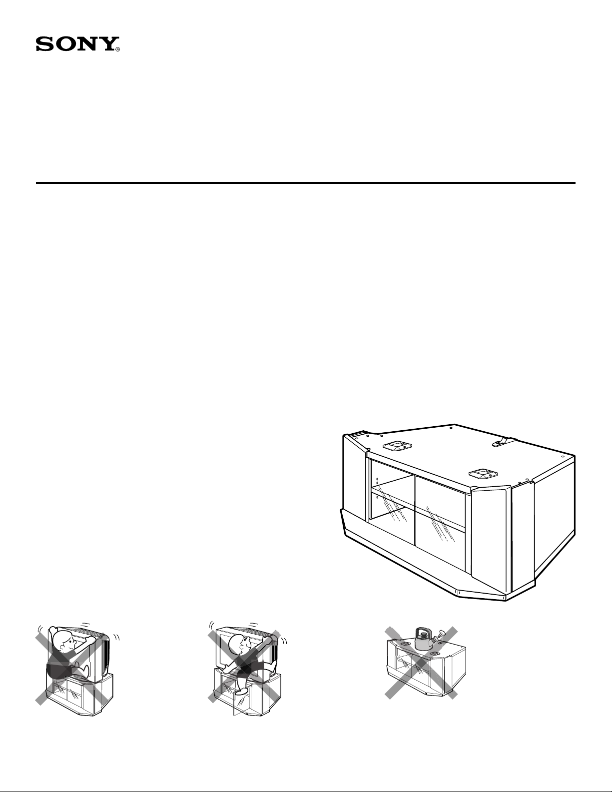
ASSEMBLED STAND
SOPORTE ENSAMBLADO
MEUBLE ASSEMBLÉ
SU-32HS2:
KV-32XBR400
KV-32XBR450
KV-32HS20
SU-36HS2:
KV-36XBR400
KV-38DRC
KV-36XBR450
KV-36HS20
WARNING / ADVERTENCIA / AVERTISSEMENT
To avoid serious
injury, do not allow
children to hang from
the television set.
Para evitar lesiones
severas, no permita
que los niños se
cuelguen del conjunto
del televisor.
Pour éviter les
blessures graves, ne
laissez aucun enfant
s’accrocher au
téléviseur.
© 2001 by Sony Electronics Inc.
To avoid injury to the
user and damage to
the stand, do not use
the shelf as a step.
Para evitar lesiones al
usuario y daño al
mueble, no use el
estante como escalon.
Pour éviter que
l’utilisateur se blesse
et que le meuble soit
endommagé, ne
l’utilisez pas comme
marchepied.
Do not place hot objects on
top of the stand. Doing so
may result in permanent
damage to the surfaces.
No coloque objetos
calientes arriba del mueble.
El hacerlo puede resultar en
daño permanente a las
superficies.
Ne posez pas d’objets
brûlants sur le dessus du
meuble. Cela endommagerait
irrémédiablement sa
surface.
Page 2
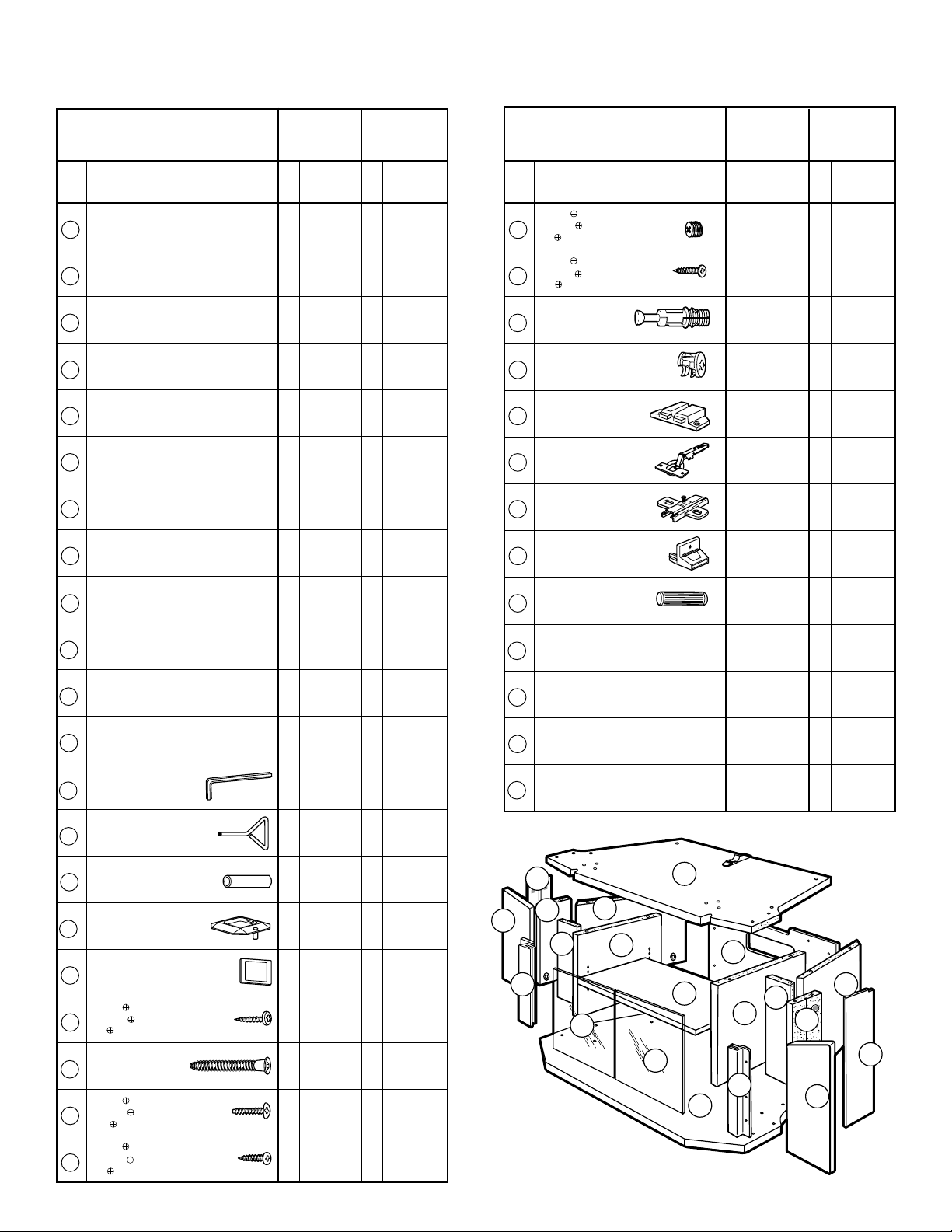
PARTS LIST
LISTA DE PARTES
LISTE DES PI
Item Description Qty Part No. Qty Part No.
Artículo
Descripción
Article
Description Qté N° de pièce Qté N° de pièce
Top board
Repisa superior
11XW2816 1 XW2817
Panneau supérieur
Adjustable shelf
Repisa ajustable
21XW2666 1 XW2683
Etagère réglable
Base board
Repisa inferior
31XW2665 1 XW2682
Panneau inférieur
Right front
Frontal derecho
41XW2667 1 XW2684
Avant droit
Left front
Frontal izquierdo
51XW2668 1 XW2685
Avant gauche
Side back
Panel lateral trasero
62XW2669 2 XW2686
Panneau latéral
Inner board
Soporte interior
72XW2672 2 XW2689
Panneau intérieur
Back panel
Panel trasero
81
Panneau arrière
Front support
Soporte frontal
92XW2671 2 XW2688
Support avant
Right door
Puerta derecha
10 1 XW2673 1 XW2690
Porte droite
Left door
Puerta izquierda
11 1 XW2674 1 XW2691
Porte gauche
Glass door
Puerta de vidrio
12 2 G0339 2 G0340
Porte vitrée
Allen wrench
Llave Allen
A1M0018 1 M0018
Clé Allen
Y driver
Desarmador "Y"
B1M0203 1 M0203
Clé en Y
Metal tube
Tubo metalico
C4M0019 4 M0019
Tube métallique
Stop guide
Topes guía
D2P0236 2 P0236
Butoir
Strike plate
Placa receptora
E2M0202 2 M0202
Gâche
Screw M3x16
Tornillo M3x16
F2S0034 2 S0034
Vis M3x16
Screw
Tornillo Confirmat
G 8S0035 8 S0035
Vis
Screw M4x16
Tornillo M4x16
H1S0122 1 S0122
VIS M4x16
Screw #6x
Tornillo #6x5/8" (Negro)
I18S0030 18 S0030
Vis #6x
È
CES
MODEL:
MODELO:
MODELE:
(Hex. Socket head)
(Hexagonale à tête creuse)
5
/8" (Black)
5
/8" (Noire)
SU-32HS2
SU-32HS2
SU-32HS2
Cant
No.parte
XW2680-1
SU-36HS2
SU-36HS2
SU-36HS2
Cant
No.parte
1
XW2692-1
MODEL:
MODELO:
MODELE:
Item Description Qty Part No. Qty Part No.
Artículo
Descripción
Article
Description Qté N° de pièce Qté N° de pièce
Screw M8x8
Tornillo M8x8
J6S0063 6 S0063
Vis M8x8
5
Screw #6x
Tornillo #6x5/8" (Plata)
K16S0127 16 S0127
Vis #6x
Spreading bolt
Esprea moldeada
L12B0077 12 B0077
Boulon d'écartement
Cam casting
Leva moldeada
M12B0056 12 B0056
Came
Magnet
Receptor magnético
N1P0159-1 1 P0159-1
Aimant
Concealed hinge
Bisagra oculta
O4M0204 4 M0204
Charnière invisible
Mounting plate
Placa de montaje
P4M0201 4 M0201
Plaque de fixation
TV clip holder
Hevilla de plastico
Q1P0178 1 P0178
Porte-pince du téléviseur
Dowel Ø8x30
Espiga Ø8x30
R12W0092 12 W0092
Goujon Ø8x30
Door frame
Marco de la puerta
S2M0199 2 M0200
Cadre de porte
Side cover (Right)
Cubierta lateral (Derecha)
T1XP0082 1 XP0080
Couvercle latéral (Droit)
Side cover (Left)
Cubierta lateral (Izquierda)
U1XP0083 1 XP0081
Couvercle latéral (Gauche)
Dual lock band
Tira de sellado doble
V16P0216 16 P0216
Courroie à double fixation
U
11
5
S
/8" (Silver)
5
/8" (Argentée)
(pre-installed)
(pré-installée)
6
9
(pre-instalada)
(pre-attached)
(pre-instalada)
(pré-montée)
7
1
2
12
SU-32HS2
SU-32HS2
SU-32HS2
Cant
No.parte
8
9
7
SU-36HS2
SU-36HS2
SU-36HS2
Cant
No.parte
6
4
12
S
3
10
T
Page 3
NOTES ON ASSEMBLY
● You will need a medium size Phillips head screwdriver.
● Assemble the stand only by the method shown in this
instruction sheet.
● Assemble the stand near the location where the stand will be used.
● The circled letters in the illustrations are the same as those in the "PARTS LIST".
For easier assembly, line up the parts in the order they will be required.
NOTES D’ASSEMBLAGE
● Vous aurez besoin d’un tournevis cruciforme de taille moyenne.
● Assemblez le meuble uniquement selon la méthode décrite dans ce mode d’emploi.
● Assemblez le meuble près de l’endroit où il sera utilisé.
● Les lettres entourées dans les schémas sont les mêmes que celles figurant dans la
liste « LISTE DES PIÈCES ». Afin de faciliter l’assemblage, alignez les pièces par
ordre de montage.
NOTAS ACERCA DEL MONTAJE
● Usted necesitará un desarmador mediano de cruz.
● Ensamble el soporte de televisor siguiendo unicamente el metodo mostrado en
estas instrucciones.
● Haga el montaje cerca del lugar donde se usará.
● Las letras encerradas en círculo en las ilustraciones, son las mismas letras en la
"LISTA DE PARTES". Para facilitar el montaje alinie las partes en el orden en
que serán usadas.
REPLACEMENT PARTS INFORMATION
Review parts list before assembly.
Please examine all packing material before discarding.
If any parts are missing or damaged, identify and refer to
the instructions on the enclosed
To purchase replacement parts only, call the telephone
number listed below.
1-619-661-6136 for residents of the United States.
INFORMACION PARA PARTES DE REEMPLAZO
Revise la lista de partes antes de ensamblar.
Por favor examine el contenido del empaque antes de tirarlo.
Si alguna parte falta o esta dañada, identifiquela y siga las
instrucciones para reportarla en la
Para ordenar partes de reemplazo, llame al tel.
1-619-661-6136 para residentes de los Estados Unidos.
INFORMATIONS SUR LES PIÈCES DE RECHANGE
(Concernent uniquement le meuble de télévision)
Vérifiez toutes les pièces avant l’assemblage.
Veuillez examiner tous les emballages avant de les jeter.
Si certaines pièces sont manquantes ou défectueuses, reportez-
vous aux instructions de la
Pour l’achat de pièces de rechange uniquement, appelez le numéro
1-619-661-6136 pour les habitants des États-Unis.
(TV stand parts only)
warranty card.
(Solo para soporte de TV)
tarjeta de garantía.
carte de garantie jointe.
ci-dessous.
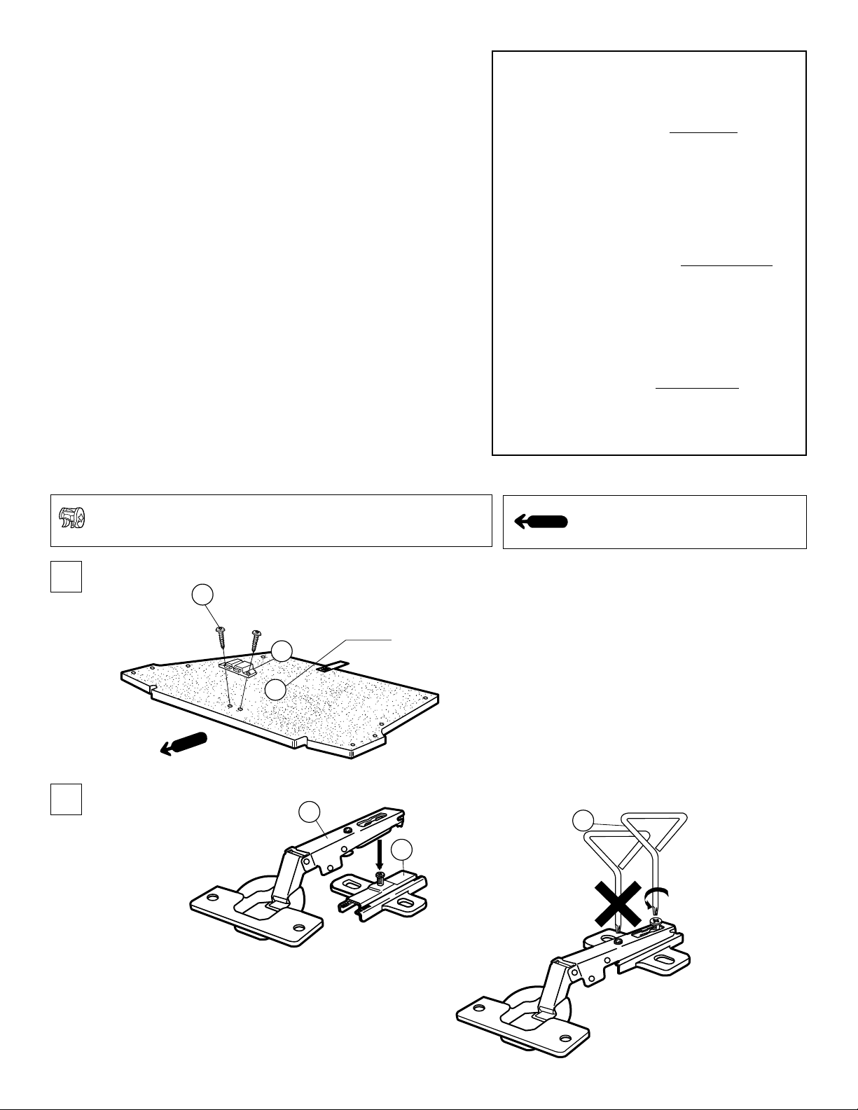
1
2
NOTE: Cam casts are pre-installed into wood pieces.
NOTA: Las "levas moldeadas" estan pre-instaladas en las piezas de madera.
NOTE: Les cames sont pré-installées dans les pièces en bois.
F x 2
UNFINISHED SIDE
N
LADO SIN ACABADO
CÔTÉ NON TERMINÉ
1
O
P
Arrow direction shows front.
La dirección de la flecha indica el frente.
La direction de la flèche indique le devant.
B
Page 4
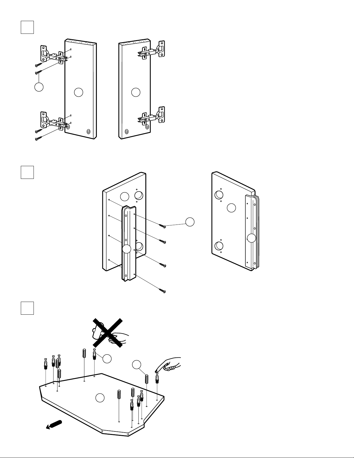
3
4
K x 8
5 4
11
10
I x 8
S
S
5
L x 8
3
INCORRECT
INCORRECTO
INCORRECT
R x 6
CORRECT
CORRECTO
CORRECT
Page 5

6
OK
Turn clockwise.
Dele vueltas en el
sentido de las
manecillas del reloj.
Tournez dans le
sens des aiguilles.
1
M x 8
7
9
5
6
6
A
4
Spreading
bolt hole
Agujero para
la esprea moldeada
Orifice du boulon
d’écartement
3
2
NOTE: The arrow mark on the cam casts
must point towards the edge of board.
NOTA: La flecha señalada en la "leva moldeada"
debe apuntar hacia la orilla de la tabla.
NOTE: La flèche sur les cames doit être pointée
vers le bord du panneau.
A
7
R x 6
9
5
L x 4
7
9
8
6
G x 8
5
7
3
1
3
6
6
7
4
When attaching the top board to the front and back panels do not
tighten the screws. For proper alignment, hold the panels in place,
and then finish tightening the screws.
Al instalar la repisa superior a los laterales frontales y posteriores no
apriete los tornillos. Para una alineación apropiada, sujete los
laterales en posición, y entonces termine de apretar los tornillos.
Lorsque vous fixez le panneau supérieur aux panneaux avant et
arrière, ne serrez pas les vis. Pour un alignement correct, maintenez
les panneaux en place puis terminez de serrer les vis.
7
7
9
6
4
Page 6

10
1
5
7
11
11
7
2
C x 4
3
11
S
5
7
5
2
3
4
1
S
6
Choose the appropriate holes for shelf adjustment
depending on the components to be installed.
Escoja los agujeros adecuados para ajustar la
repisa dependiente a los componentes que se
instalarán.
Le choix des trous appropriés au réglage de
l’étagère dépend des appareils à installer.
4
10
6
K x 4
4
10
12
K x 4
Tighten these 2 screws first.
Apriete estos 2 tornillos primero.
Serrez d’abord ces 2 vis.
I x 8
8
I x 2
D x 2
10
11
1
6
2
6
3
5
Page 7

13
LEFT DOOR
LA PUERTA IZQUIERDA DE VIDRIO
PORTE GAUCHE
E
1
5
11
2
12
7
J x 6
DIMENSIONS OF GLASS DOOR
DIMENSIONES DE LA PUERTA DE VIDRIO
DIMENSIONS DE LA PORTE VITRÉE
B
DISTANCE
DISTANCIA
DISTANCE
TEMPERED GLASS
A
A
B
3
SU-32HS2
mm
(inch)
262.6
(10 11/32)
363.0
(14 5/16)
FOLLOW THE SAME INSTRUCTIONS TO INSTALL
THE RIGHT DOOR.
SIGA LAS MISMAS INSTRUCCIONES PARA
INSTALAR LA PUERTA DERECHA DE VIDRIO.
SUIVEZ LES MÊMES INSTRUCTIONS POUR
INSTALLER LA PORTE DROITE.
Tempered Glass / Vidrio Templado / Verre Trempé
The glass panels in this stand are made of tempered glass. Although it is more shockresistant than ordinary glass, tempered glass may shatter if it receives a sudden
shock. Be careful not to drop or scratch the glass.
La puerta de vidrio de este soporte de televisor esta hecha de vidrio templado.
Aunque es mas resistente a impactos que el vidrio ordinario, puede fracturarse si
recibe un golpe repentino. Tenga cuidado en no dejar caer o en rayar el vidrio.
Les panneaux en verre de ce meuble sont en verre trempé. Bien qu’il résiste mieux
aux chocs que le verre ordinaire, le verre trempé peut se fissurer s’il est soumis à un
choc brutal. Veillez à ne pas le laisser tomber et à ne pas le griffer.
SU-36HS2
mm
(inch)
279.6
(11)
387.4
(15 1/4)
CAUTION / PRECAUCION / ATTENTION
PLEASE INSTALL GLASS DOORS AFTER THE STAND IS SET AT THE FINAL LOCATION.
REMOVE GLASS DOORS PRIOR TO MOVING THE STAND.
FAVOR DE INSTALAR LAS PUERTAS DE VIDRIO DESPUES DE COLOCAR EL MUEBLE EN SU
POSICION FINAL.
QUITE LAS PUERTAS DE VIDRIO ANTES DE MOVER EL MUEBLE.
INSÉREZ LES PORTES EN VERRE UNE FOIS LE MEUBLE INSTALLÉ DANS SON EMPLACEMENT
DÉFINITIF.
RETIREZ LES PORTES EN VERRE AVANT DE DÉPLACER LE MEUBLE.
Page 8

14
Screw A
Tornillo A
Vis A
Front-to-back angle-adjust
Ajuste del ángulo frontal-trasero
Réglage de l’angle avant-arrière
Loosen this screw and push/pull door
to align bottom.
Afloje este tornillo y empuje/jale la
puerta para alinear la parte inferior.
Desserrez cette vis et alignez le bas
de la porte en appuyant ou en tirant
celle-ci.
Loosen this screw and push/pull
door to align top.
Afloje este tornillo y empuje/jale la
puerta para alinear la parte superior.
Desserrez cette vis et alignez le
dessus de la porte en appuyant ou
en tirant celle-ci.
Screw B
Tornillo B
Vis B
Side-to-side angle-adjust
Ajuste del ángulo lado-lado
Réglage de l’angle latéral
FOLLOW THE SAME INSTRUCTIONS TO INSTALL THE RIGHT DOOR.
SIGA LAS MISMAS INSTRUCCIONES PARA INSTALAR LA PUERTA DERECHA DE VIDRIO.
SUIVEZ LES MÊMES INSTRUCTIONS POUR INSTALLER LA PORTE DROITE.
Loosen this screw to align top of
door.
Afloje este tornillo para alinear la
parte superior de la puerta.
Desserrez cette vis pour aligner
le dessus de la porte.
Loosen this screw to align bottom
of door.
Afloje este tornillo para alinear la
parte inferior de la puerta.
Desserrez cette vis pour aligner le
bas de la porte.
Page 9

15
2
INSTALLING THE TV
INSTALACIÓN DEL TELEVISOR
INSTALLATION DU TÉLÉVISEUR
1
U
Dual lock bands are pre-attached to pieces 4 , 5 , T , U .
Las tiras de sellado doble estan pre-instaladas a las piezas
4 , 5 , T , U .
Les courroies à double fixation sont déjà fixées aux pièces
4 , 5 , T , U.
Slide top of "rib" of side cover T , U into
groove of right front panel 4 , and left front
panel 5 upwards until it hits the top board
1 .
1
Deslice la parte superior de la costilla de la
cubierta lateral T , U dentro de la ranura
del panel frontal derecho 4 , y el panel
frontal izquierdo 5 hacia arriba hasta que
llegue a la repisa superior 1 .
Faites glisser la “nervure” du panneau
latéral T , U dans la rainure du panneau
avant droit 4 et le panneau avant gauche
5 vers le haut jusqu’à ce qu’il touche le
panneau supérieur 1 .
2
Swing bottom portion downwards to
attach.
Haga un movimiento circular de la
parte inferior hacia abajo para
adjuntarla.
T
Basculez la partie inférieure vers le
bas pour la fixer.
CAUTION / PRECAUTION / ATTENTION
Attach side covers T & U after installing TV.
Adjunte las cubiertas laterales T y U despues
de instalar la TV.
Fixez les panneaux latéraux T & U après avoir
installé le téléviseur.
16
NOTE: FOLLOWING STEP 16 WILL INCREASE THE STABILITY OF THE FINAL TELEVISION/STAND UNIT.
NOTA: SIGUIENTE PASO
16
NOTA: L’ÉTAPE
CI-DESSOUS RENFORCE LA STABILITÉ DE L’ENSEMBLE TÉLÉVISEUR/MEUBLE.
3
When attaching this side cover to the
stand, push on the locations for
maximum adhesion.
Cuando coloque esta cubierta lateral al
soporte del televisor, presione en el
lugar para una maxima adhesion.
Lorsque vous fixez ce panneau latéral
au meuble, appuyez aux endroits
indiqués pour une adhérence maximale.
16
INCREMENTARÁ LA ESTABILIDAD DEL COMBINADO TELEVISOR / SOPORTE.
Attach the TV clip holder to the TV with the
1
screw. Then, insert the buckle into the slot on
the TV clip holder.
Ajuste la hevilla de plastico al televisor con el
tornillo. Luego, inserte el cinturón de seguridad
en la ranura de la parte posterior de la hevilla de
plastico.
Fixez le porte-pince du téléviseur au téléviseur à
l’aide de la vis. Insérez ensuite la boucle dans la
fente du porte-pince du téléviseur.
H
Tighten the strap by
2
pulling in downward direction.
Apriete la correa jalando
hacia abajo.
Serrez la courroie en tirant
vers le bas.
Q
Page 10

DIMENSIONS
DIMENSIONES
DIMENSIONS
C
Weight : SU-32HS2 SU-36HS2
Approx. 36 Kg (79 lbs.) Approx. 42 Kg (93 lbs.)
Peso : SU-32HS2 SU-36HS2
Aprox. 36 Kg (79 lbs.) Aprox. 42 Kg (93 lbs.)
Poids : SU-32HS2 SU-36HS2
Approx. 36 Kg (79 lbs.) Approx. 42 Kg (93 lbs.)
A
B
Unit : mm (inches)
Unidad : mm (pulgadas)
Unité : mm (pouces)
SU-32HS2 SU-36HS2
DISTANCE
DISTANCE
DISTANCIA
DISTANCE
A 889.0 35 985.1 38 25/32
B 498.5 19 5/8 532.4 20 31/32
E
D
F
G
C 373.0 14 11/16 397.4 15 21/32
D 424.0 16 11/16 448.4 17 21/32
E 441.0 17 3/8 466.4 18 11/32
F 577.8 22 3/4 607.2 23 29/32
G 543.8 21 13/32 570.0 22 13/32
H 375.0 14 3/4 375.0 14 3/4
I 655.4 25 13/16 691.8 27 7/32
J 657.9 25 15/16 694.3 27 5/16
K 214.4 8 7/16 226.5 8 29/32
L 184.4 7 1/4 196.5 7 3/4
M 154.4 6 1/16 166.5 6 17/32
N 124.4 4 29/32 136.5 5 3/8
O 139.8 5 1/2 151.9 5 21/32
P 169.8 6 11/16 181.9 7 5/32
Q 199.8 7 7/8 211.9 8 11/32
R 229.8 9 1/32 241.9 9 1/2
mm inch mm inch
N
M
L
K
CARRYING CAPACITY OF EACH SHELF
RESISTENCIA DE CADA REPISA
CAPACITÉ DE RESISTANCE DES ÉTAGÈRES
SU-32HS2
100 kg (220 lbs. 8 oz)
25 kg (55 lbs. 2 oz)
R
Q
P
O
H
I
J
SU-36HS2
128 kg (282 lbs. 4 oz)
25 kg (55 lbs. 2 oz)
25 kg (55 lbs. 2 oz)
SONY ELECTRONICS INC. PRINTED IN USA
SONY ELECTRONICS INC. IMPRESO EN EUA
SONY ELECTRONICS INC. IMPRIMÉ AUX ÉTATS-UNIS
25 kg (55 lbs. 2 oz)
Design and specifications subject to change without notice.
Diseño y especificaciones sujetos a cambio sin previo aviso.
Conception et caractéristiques susceptibles d’être modifiées sans avis préalable.
Page 11

FOR RESIDENTS OF CANADA
POUR LES HABITANTS DU CANADA
PARA RESIDENTES DE CANADIENSES
Please examine all packaging materials before discarding.
If any parts are missing or damaged,
please review the parts list found in the assembly manual,
identify the missing or damaged part,
and call the Sony customer sevice center at
SU-32HS2
SU-36HS2
1-877-779-9929.
Veuillez examiner tout l’emballage avant de le jeter.
Si des pièces sont manquantes ou endommagées,
veuillez vérifier les pièces qui se trouvent dans le manuel de montage,
identifier les pièces manquantes ou endommagées,
et appeler le service client de Sony au numéro:
1-877-779-9929.
Por favor examine todo el material de empaque antes de tirarlo.
Si cualquier parte resulta faltante o está dañada,
por favor revise la lista de partes que se encuentra
en el manual de ensamble, identifique la parte dañada o faltante,
y llame al centro servicio al cliente de Sony al
1-877-779-9929.
Page 12

FOR RESIDENTS OF THE UNITED STATES
POUR LES HABITANTS DES ÉTATS-UNIS
PARA RESIDENTES DE LOS ESTADOS UNIDOS
S
LIMITED WARRANTY
Sony Electronics Inc. (“Sony”) warrants this product against defects in material or workmanship, subject to
any conditions set forth as follows:
1. This warranty is expressly limited to the replacement of Sony TV Stand parts and components.
2. For a period of 30 days from the date of purchase, Sony will supply parts that are determined to be
defective or missing, at no charge, to the original purchaser. After the warranty period, you will be
charged for all orders.
This warranty does not cover damages which occur in shipment or failures due to acts of God, accident,
misuse, abuse, negligence, faulty installation, misapplication, setup, improper maintenance, commercial use,
or modification of, or to any part of the product. This warranty does not cover Products sold AS IS or WITH
ALL FAULTS. This warranty is valid only in the United States.
Proof of purchase in the form of a bill of sale or receipted invoice, which is evidence that the unit is within the
warranty period, must be presented to obtain the replacement parts.
SU-32HS2
SU-36HS2
TV Stand
REPLACEMENT PARTS AS PROVIDED UNDER THIS WARRANTY ARE THE EXCLUSIVE REMEDY OF THE CONSUMER. SONY SHALL NOT BE LIABLE FOR ANY INCIDENTAL OR CONSEQUENTIAL DAMAGES FOR BREACH OF ANY EXPRESS OR IMPLIED WARRANTY ON THIS PRODUCT. EXCEPT TO THE EXTENT PROHIBITED BY APPLICABLE LAW, ANY IMPLIED WARRANTY
OF MERCHANTABILITY OR FITNESS FOR A PARTICULAR PURPOSE ON THIS PRODUCT IS LIMITED IN DURATION TO THE DURATION OF THIS WARRANTY.
Some states do not allow the exclusion or limitation of incidental or consequential damages, or allow limitations on how long an implied warranty lasts, so the above limitations or exclusions may not apply to you. This
warranty gives you specific legal rights, and you may have other rights which vary from state to state.
In order to obtain replacement parts, you must provide a PROOF OF PURCHASE and complete the information on this warranty card. Fax or mail these to:
Tocabi America Corp.
755 Main Street, Chula Vista, CA 91911
Fax No.: (619) 656-8181
www.tocabi.com
Name:
Address:
City: State: Zip Code: Phone:
Model:
Part No. Description Quantity Reason
4-064-678-01 Printed in USA
R0811-1
 Loading...