

Page 1
STR-VX500
SERVICE MANUAL
This set is the tuner and amplifier
section in MHC-VX500.
SPECIFICATIONS
Amplifier section
The following measured at AC 120, 220, 240V 50/60 Hz
DIN power output (Rated) (FRONT)
120 + 120W (6 Ω at 1kHz DIN)
Continuous RMS power output (Reference)
FRONT SPEAKER: 150 + 150W
(6 Ω at 1kHz, 10% THD)
Inputs MD/VIDEO 1 IN (phono jacks): voltage
450/250mV, impedance 47kΩ
AV INPUT AUDIO (phono jacks): voltage
250mV, impedance 47kΩ
MIX MIC 1/2 (phone jack): sensitivity 1mV,
impedance 10kΩ
Output MD/VIDEO 1 OUT (phono jacks): voltage
450/250mV, impedance 1kΩ
PHONES (stereo phone jack): accepts
headphones of 8Ω or more.
FRONT SPEAKER:
accepts impedance of 6 to 16Ω
REAR SPEAKER:
accepts impedance of 16Ω
SUPER WOOFER:
Voltage 1V, impedance 1kΩ
Tuner section
FM stereo, FM/AM superheterodyne tuner
FM tuner section
Tuning range 87.5 – 108.0MHz
Antenna terminals 75Ω unbalanced
Intermediate frequency 10.7MHz
AM tuner section
Tuning range MW: 531 – 1,602kHz (with the MW tuning
Intermediate frequency 450kHz
Antenna AM loop antenna External antenna terminal
General
Power requirements 120V, 220V or 230 – 240V AC, 50/60Hz
Power consumption 290W
Dimensions (w/h/d) Approx. 288 × 205 × 375mm
Mass Approx. 8.6kg
E Model
interval set at 9kHz)
530 – 1,710kHz (with the MW tuning
interval set at 10kHz)
SW: 5.95 – 17.90MHz (with the SW tuning
interval set at 5kHz)
Adjustable with voltage selector
MICROFILM
Design and specifications are subject to change without notice.
FM STEREO/FM-AM RECEIVER
Page 2

TABLE OF CONTENTS
1. GENERAL ····································································· 3
2. DISASSEMBLY
2-1. Sliding Panel Assembly ······················································ 5
2-2. Level Slider ········································································ 5
3. SERVICE MODE·························································· 6
4. DIAGRAMS
4-1. Circuit Boards Location ····················································· 9
4-2. Block Diagrams
• Main Section ·································································· 10
• Power Section ································································ 11
4-3. Printed Wiring Board Main Section ······························· 13
4-4. Schematic Diagram Main (1/2) Section ························· 14
4-5. Schematic Diagram Main (2/2) Section ························· 15
4-6. Schematic Diagram Power Amp Section ······················· 16
4-7. Printed Wiring Board Power Amp Section····················· 17
4-8. Schematic Diagram Display Section ······························ 18
4-9. Printed Wiring Board Display Section ··························· 19
4-10. Schematic Diagram Sliding Panel Section ····················· 20
4-11. Printed Wiring Board Sliding Panel Section ·················· 21
4-12. Printed Wiring Board Trans Section······························· 22
4-13. Schematic Diagram Trans Section ································· 23
4-14. Schematic Diagram AV/Mic Section······························24
4-15. Printed Wiring Board AV/Mic Section ··························· 25
4-16. IC Block Diagrams ··························································· 26
4-17. IC Pin Function ································································ 29
5. EXPLODED VIEWS
5-1. Case and Sliding Panel Section ········································ 32
5-2. Front Panel Section ·························································· 33
5-3. Slide Mechanism Section ················································· 34
5-4. Circuit Boards and Back Panel Section···························· 35
6. ELECTRICAL PARTS LIST ··································· 36
SAFETY-RELATED COMPONENT WARNING !!
COMPONENTS IDENTIFIED BY MARK ! OR DO TTED LINE WITH
MARK ! ON THE SCHEMATIC DIAGRAMS AND IN THE PARTS
LIST ARE CRITICAL TO SAFE OPERATION. REPLACE THESE
COMPONENTS WITH SONY PARTS WHOSE PART NUMBERS
APPEAR AS SHOWN IN THIS MANUAL OR IN SUPPLEMENTS
PUBLISHED BY SONY.
2
Page 3
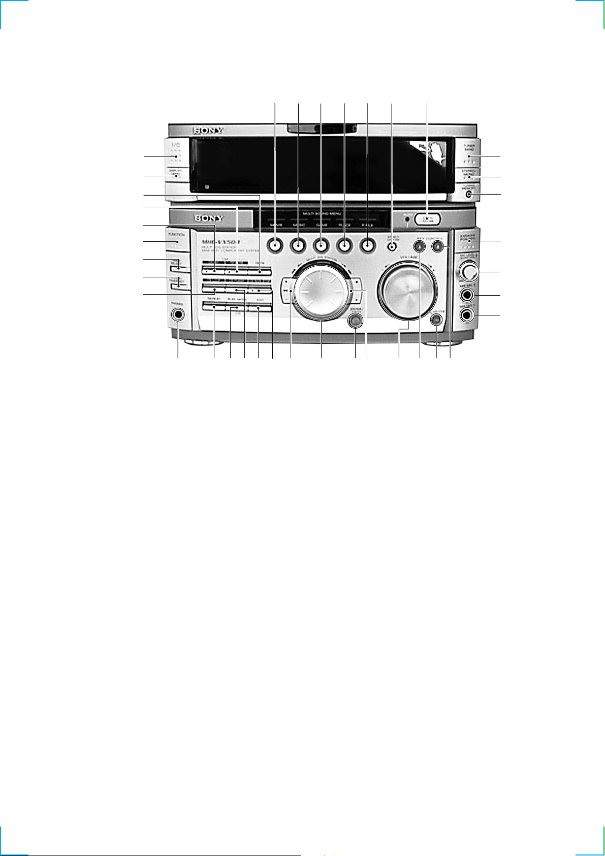
Front Panel
SECTION 1
GENERAL
ef
ed
es
ea
e;
wl
wk
wj
wh
wg
wf
wd
ws
wa
w;
1
ql
2
3 4
qj
5
qh
6
qg
7
8
9
0
qa
qs
eg
qd
ej ehqk
qf
1 MOVIE button
2 MUSIC button
3 GAME button
4 PLACE button
5 P FILE button
6 EFFECT ON/OFF button
7 OPEN/CLOSE button
8 TUNER BAND button
9 STEREO/MONO button
0 MEMORY button
qa KARAOKE PON/MIX button
qs MIC LEVEL/ECHO VOL dial
qd MIX MIC1 jack
qf GROOVE button
qg VOLUME dial
qh M + button
qj ENTER/NEXT button
qk MULTI JOG STATION dial
ql m – button
w; NON-STOP button
wa EDIT button
ws FLASH button
wd PLAY MODE button
wf REPEAT button
wg PHONES jack
wh LOOP button
wj CLOCK/TIMER SET button
wk TIMER SELECT button
wl FUNCTION button
e; PROLOGIC button
ea DSP button
es DBFB button
ed DISPLAY/DEMO button
ef I/1 (POWER) button
eg MIX MIC2 jack
eh KEY CONTROL (#)
ej KEY CONTROL (2)
3
Page 4
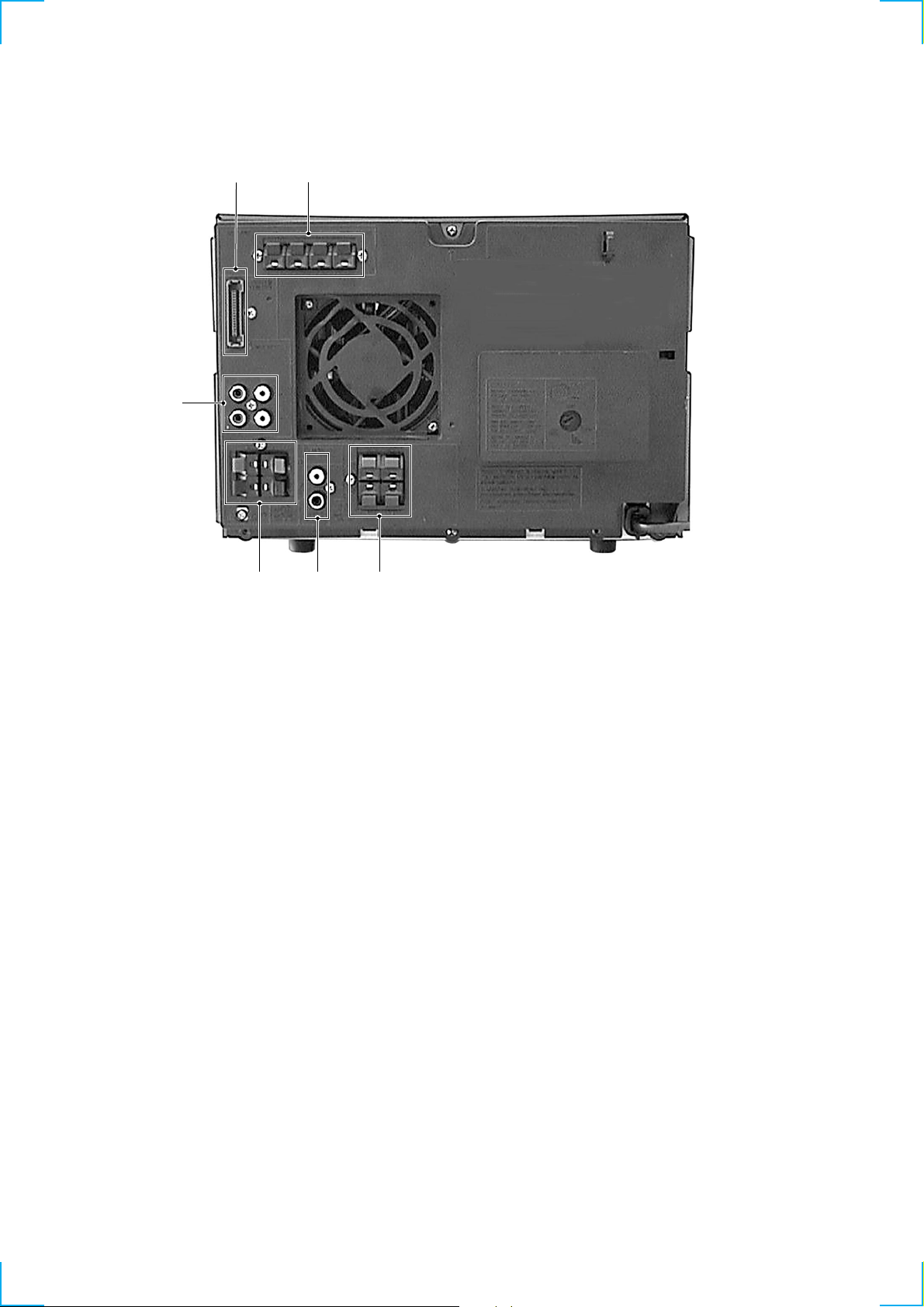
Rear Panel
6
1
5
2
4
3
1 SYSTEM CONTROL jack
2 ANTENNA terminal
3 REAR SPEAKER terminal
4 MONITOR OUT jack
5 FRONT SPEAKER terminal
6 MD/VIDEO 1 jack
4
Page 5
SECTION 2
DISASSEMBLY
Note: Follow the disassembly procedure in the numerical order given.
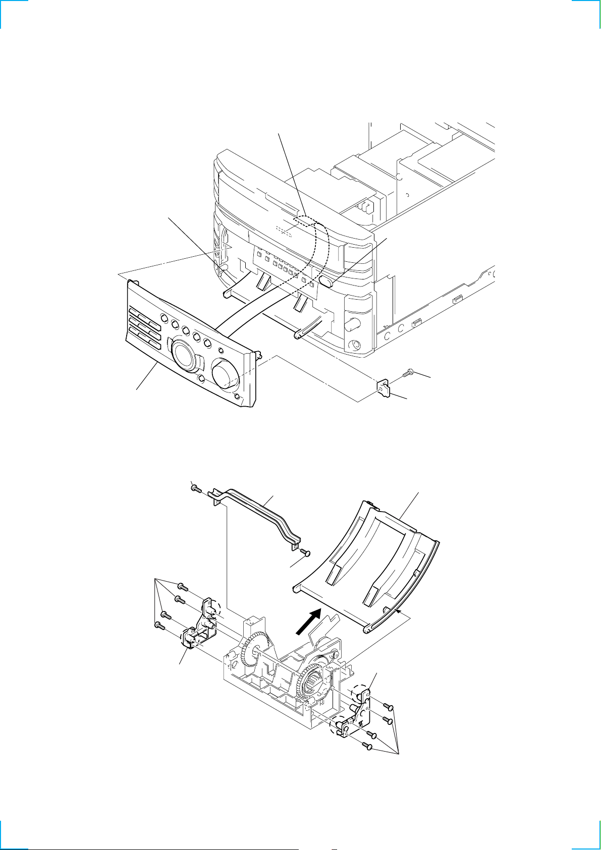
2-1. SLIDING PANEL ASSEMBLY
4
Flat type cable (19 core)
Slide mechanism
1
Push the OPEN/CLOSE button to
open the Sliding panel assembly.
5
Sliding panel assembly
2-2. LEVEL SLIDER
(Perform this DISASSEMBLY after the front panel is removed.)
1
Screw (BVTP2.6 × 8)
3
Top bracket
4
Four screws
(BVTP2.6 × 8)
5
Holder (L) assembly
b
a
2
Screw
(BVTP2.6 × 8)
2
Screw (BVTP 3 × 8)
3
Holder level
8
Remove the Level slider direction of arrow.
7
Holder (R) assembly
a
NOTE FOR INSTALLATION:
Attach in the reverse order, but make sure the rollers (a, b) of the
holder (L) assembly and holder (R) assembly fit into the grooves of
the level slider.
b
Four screws (BVTP2.6 × 8)
6
5
Page 6
SECTION 3
SERVICE MODE
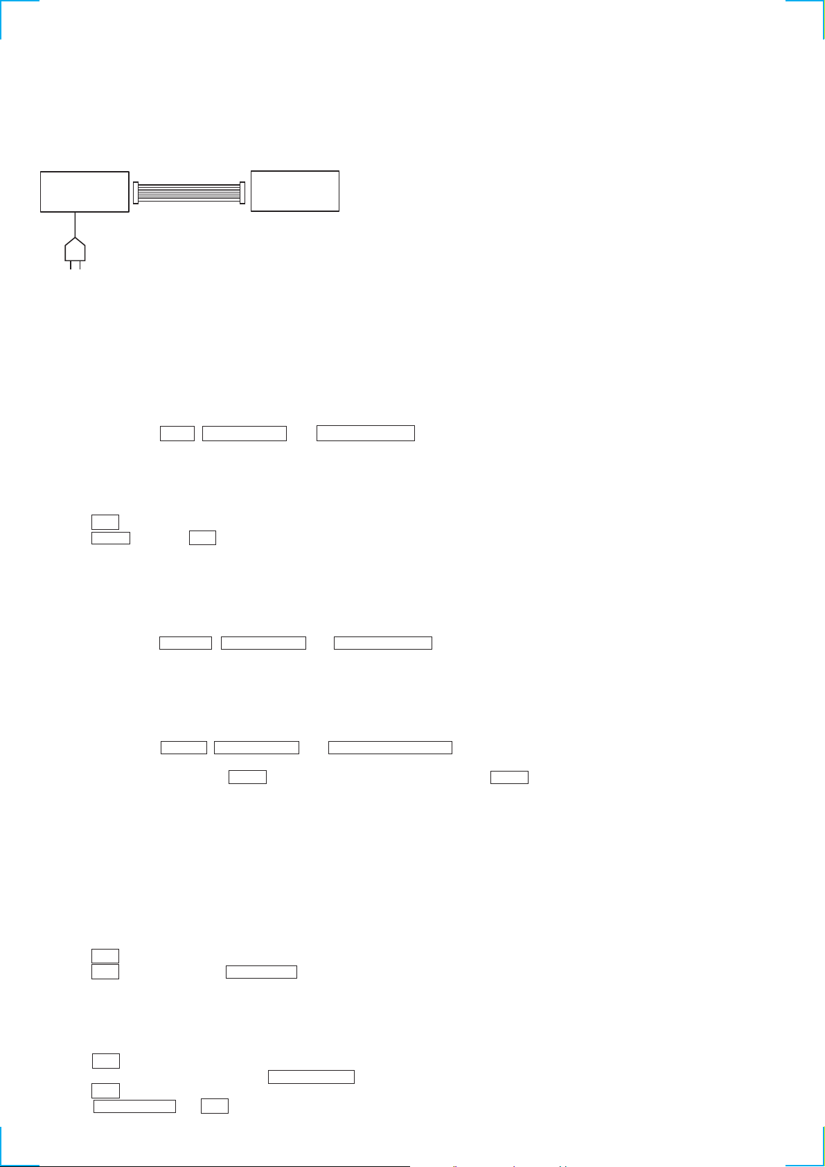
Connections and Operations When Used Alone
Normally, use the unit connected to the HTC-VX500 as follows.
Basically, when servicing the unit, connect the unit as follows.
UNIT
SYSTEM CONTROL 17P
AC IN
Even when not connected to the HTC-VX500, the unit can operate alone as it mounts a power supply (some functions will however not be
available).
MC Cold Reset
• The cold reset clears all data including preset data stored in the RAM to initial conditions. Execute this mode when returning the set to the
customer.
Procedure:
1. Press three buttons EDIT , ENTER/NEXT , and DISPLAY/DEMO simultaneously.
2. The fluorescent indicator tube becomes blink instantaneously, and the set is reset.
CD Delivery Mode (This mode can be used only when the HTC-VX500 is connected.)
• This mode moves the pick-up to the position durable to vibration. Use this mode when returning the set to the customer after repair.
Procedure:
1. Press 1/1 button to turn the set ON.
2. Press LOOP button and 1/1 button simultaneously.
3. A message “LOCK” is displayed on the fluorescent indicator tube, and the CD delivery mode is set.
MC Hot Reset
• This mode resets the set with the preset data kept stored in the memory . The hot reset mode functions same as if the po wer cord is plugged
in and out.
Procedure:
1. Press three buttons REPEAT , ENTER/NEXT , and DISPLAY/DEMO simultaneously.
2. The fluorescent indicator tube becomes blink instantaneously, and the set is reset.
HTC-VX500
Sled Servo Mode (This mode can be used only when the HTC-VX500 is connected.)
• This mode can run the CD sled motor freely. Use this mode, for instance, when cleaning the pick-up.
Procedure:
1. Select the function “CD”.
2. Press three buttons FLASH , ENTER/NEXT , and KARAOKE PON/MIX simultaneously.
3. The Sled Servo mode is selected, if “CD” is blinking on the fluorescent indicator tube.
4. With the CD in stop status, press M + button move the pick-up to outside track, or – m button to inside track.
5. To exit from this mode, perform as follows:
1) Move the pick-up to the most inside track.
2) Press three buttons in the same manner as step 2.
Note:
• Always move the pick-up to most inside track when exiting from this mode. Otherwise, a disc will not be unloaded.
• Do not run the sled motor excessively, otherwise the gear can be chipped.
Change-over of FUNCTION Name
• The FUNCTION name of external input terminal can be changed over to VIDEO 1 or MD. W ith the FUNCTION selected to “MD”, about
5dB mute is applied to the input gain.
Procedure:
1. Press 1/1 button to turn the set OFF.
2. Press 1/1 button together with FUNCTION b utton, and the power is turned on, the display of fluorescent indicator tube changes to
“MD” or “VIDEO 1” instantaneously, and thus the FUNCTION is changed over.
Change-over of AM Tuner Step between 9kHz and 10kHz
• A step of AM channels can be changed over between 9kHz and 10kHz.
Procedure:
1. Press 1/1 button to turn the set ON.
2. Select the function “TUNER”, and press TUNER/BAND button to select the BAND “MW”.
3. Press 1/1 button to turn the set OFF.
4. Press ENTER/NEXT and 1/1 buttons simultaneously, and the display of fluorescent indicator tube changes to “MW step 10” or
“MW step 9”, and thus the channel step is changed over.
6
Page 7
LED and Fluorescent Indicator Tube All Lit, Key Check Mode (Do not connect the HTC-VX500.)
Procedure:
1. Press 1/1 button to turn the set ON.
2. Press the OPEN/CLOSE button to open the sliding panel.
3. Press three buttons DELAY , ENTER/NEXT , and DISPLAY/DEMO simultaneously.
4. LEDs and fluorescent indicator tube are all turned on. Each time the MOVIE button is pressed, the fluorescent indicator tube lights up
as follows:
lights up completely n lights up partially 1 n lights up partially 2 n lights up completely.
5. Press GAME button, and the key check mode is activated.
6. In the key check mode, the fluorescent indicator tube displays “K @@ V0 J0”. Each time a button is pressed, “K”value decreases.
However, once a button is pressed, it is no longer taken into account. (@@ means the total of buttons)
“J” Value increases like 1, 2, 3 ... if rotating JOG knob in “+” direction, or it decreases like 0, 9, 8 ... if rotating in “-” direction.
“V” Value increases like 1, 2, 3 ... if rotating VOLUME knob in “+” direction, or it decreases lik e 0, 9, 8 ... if rotating in “-” direction.
7. Pressing all buttons lights up the fluorescent indicator tube completely.
8. To exit from this mode, press three buttons EDIT , ENTER/NEXT and DISPLAY/DEMO simultaneously. (COLD RESET)
9. To exit from this mode, press three buttons in the same manner as step 1, or disconnect the power cord.
CD, TAPE Deck Aging Mode (This mode can be used only when the HTC-VX500 is connected.)
This mode can be used for checking the operations of the CD player and tape deck.
• When problems occur;
Aging stops, and the stopped state is displayed on the fluorescent indicator tube.
• When no problems;
Aging continues.
Preparations:
• Set the CD on the DISC1 tray.
• Insert a commercially available tape for recording (tapes which contents can be erased, etc.) in decks A and B.
Setting the aging mode:
Press the PLAY MODE button, ENTER/NEXT button, and STEREO/MONO button together.
When the aging mode is set, the CD roulette mark blinks. To exit the mode, press the 1/1 button and turn OFF the power.
Sequence:
The aging mode is executed in the following sequence.
If the function is set to “CD” when the aging mode is set, aging is performed starting from the CD player. When set to “TAPE A” or “TAPE
B”, aging is started from deck A.
If the function is set to others, aging will not be started until the function is switched to CD or TAPE.
Aging of CD player (12 minutes)
Aging of deck A
Aging of deck B
12 minutes
Display of status:
• The aging status is displayed on the fluorescent indicator tube.
• Normally, the CD player displays the remaining aging time. But if operations ended abnormally, it displays the cause.
• During the aging of the tape deck, the operations performed will be displayed. If operations ended abnormally, this will be di splayed at the
fluorescent display tube.
CD Player
• During normal operations:
Display of fluorescent indicator tube
**1-@@
**: Displays “CD” and the remaining aging time (minutes) alternately. The remaining aging time is counted down from 12.
@@: Track number being accessed.
7
Page 8
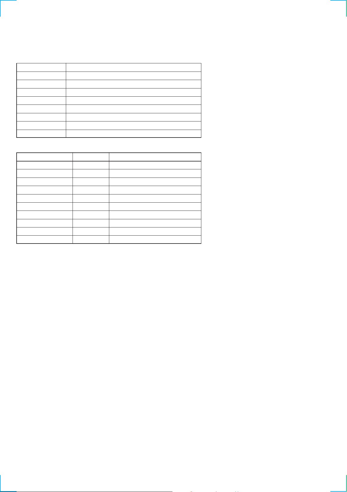
• When operations end abnormally:
Display of fluorescent display tube
Display
NO DISC ERR
FOCUS1 ERR
FOCUS2 ERR
GFS ERR
FBIAS ERR
SENSOR ERR
TABLE ERR
TRAY ERR
Tape Deck
Display of Operations
T APE A AG-1
T APE A AG-2
T APE A AG-3
T APE A AG-4
T APE A AG-5
TAPE B AG-1
TAPE B AG-2
TAPE B AG-3
TAPE B AG-4
TAPE B AG-5
Main Cause
DISC 1 is NO DISC from the beginning
Focus is not imposed properly
The focus deviated several times after the disc rotated normally
GFS ERROR
Error during focus bias adjustment
DISC 1 was found to be NO DISC by the disc sensor
The table did not rotate normally
The tray containing the BD did not operate normally
Operation
T APE A REW
T APE A FWD
T APE A FF
T APE A REV
T APE A REW
TAPE B REW
TAPE B FWD
TAPE B FF
TAPE B REV
TAPE B REW
Shutoff
2 minute playback
20 seconds or shutoff
2 minutes playback
Shutoff
Shutoff
2 minute playback
20 seconds or shutoff
2 minute playback
Shutoff
Timing of Ending
Operations during aging
• Operations are performed in the following sequence during aging.
<CD player>
1. The CD tray rotates and disc 1 is selected.
2. Chucking is performed.
3. TOC is read.
4. Track 1 played back for 2 seconds.
5. The last track is played back for 2 seconds.
6. 1 to 5 is repeated.
7. After 12 minutes of aging, aging is switched to the tape deck.
<Tape Deck>
1. The tape in deck A is rewound to the head.
2. The FWD side is played back for 2 minutes.
3. The tape is fast forwarded (FF) for 20 seconds. The following procedure is performed when the tape end is reached before the 20
seconds.
4. The REV side is played back for 2 minutes.
5. The tape is rewound to the head (REW).
6. The tape in deck B is rewound to the head.
7. The FWD side is played back for 2 minutes.
8. The tape is fast forwarded (FF) for 20 seconds. The following procedure is performed when the tape end is reached before the 20
seconds.
9. The REV side is played back for 2 minutes.
10. The tape is rewound to the head (REW).
11. Aging is switched to the CD player.
8
Page 9
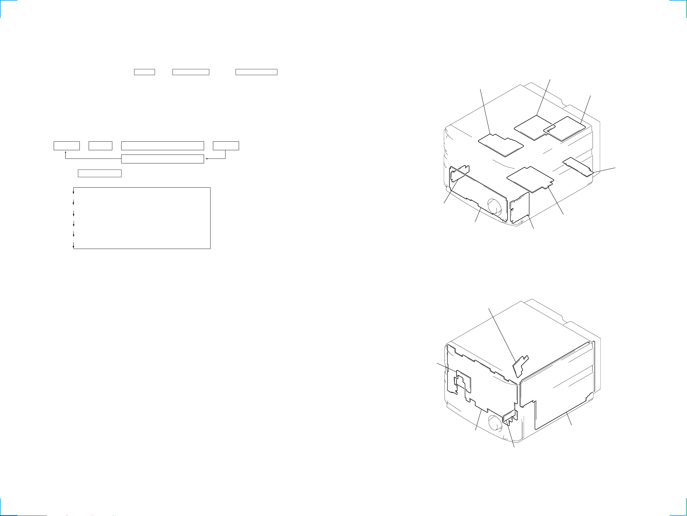
SECTION 4
MIC / ECHO board
POWER AMP board
SURR SPK board
PRIMARY board
ENCAPSULATED COMPONENT
(AM/FM TUNER)
SECONDARY board
HEADPHONE board
LOADING PANEL board
DIAGRAMS
STR-VX500
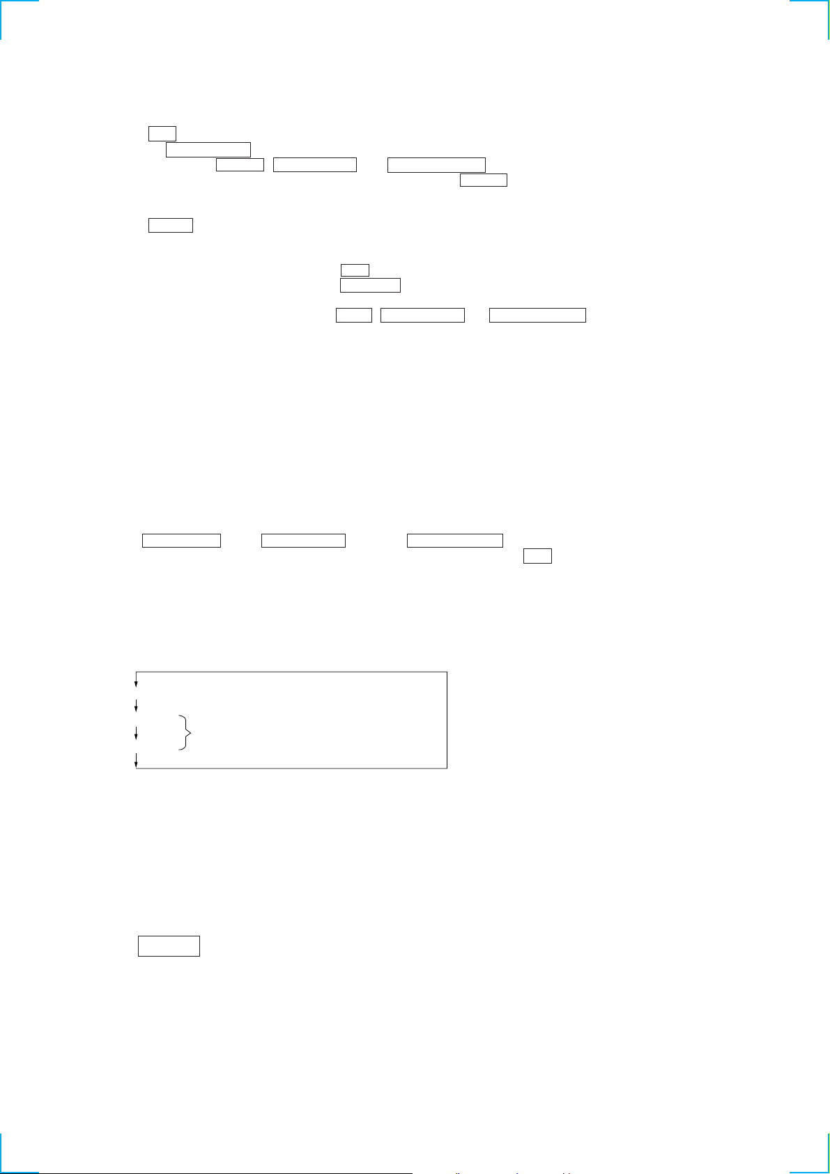
PANEL Aging Mode
This mode is used for opening and closing the sliding panel continuously.
Setting the aging mode :
With the set at standby condition, press FLASH button, ENTER/NEXT button and STEREO/MONO button together.
The aging will start and sliding panel will follow aging sequence as described below.
• When problems occur ;
Aging stops and “AGING ERROR” is displayed on the fluorescent indicator tube.
• When no problems;
Aging is carried out repeatedly. After 65000 times, “AGING STOP” is displayed and aging stops.
Aging Sequence
Stops for one second in the opened state
Panel open Panel close
n
Counts up
n n
Stops for one second in the closed state
Each time the DISPLAY/DEMO button is pressed, the display switches as follows.
Aging @@@@@ (No. of agings carried out)
OP Max @.@@ (Maximum time taken for OPEN:In seconds)
OP Min @.@@ (Minimum time taken for OPEN:In seconds)
4-1. CIRCUIT BOARDS LOCATION
CL Max @.@@ (Maximum time taken for CLOSE:In seconds)
CL Min @.@@ (Minimum time taken for CLOSE:In seconds)
MOTOR board
FRONT AV board
PANEL board
DETECTOR board
MAIN board
99
Page 10
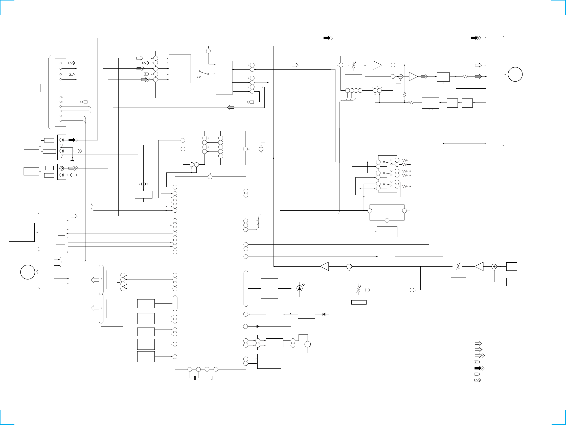
STR-VX500
4-2. BLOCK DIAGRAMS
MAIN SECTION
1
2
7
CN101
SYSTEM
CONTROL
TO
HTC-VX500
9
5
6
14
16
17
13
IIC DATA
IIC CLK
AC1
AC2
R-CH(CD R)
R-CH(PB R)
R-CH(REC R)
VIDEO
EQ
IC111(1/2)
TU
69
CD
68
V2
67
TC
66
MD/V1
65
SELECT
SWITCH
R-CH
SPEANA
SELECTOR
IC505
2
42 41
EQ
AMP
BPF FILTER
SPEANA
IC506
4
3
60
57
58
VOLUME
IC111(2/2)
MICON
INTERFACE
33
32 34
123
36
57
40
38
30
39
R-CH
AMP
IC113(2/2)
SELECTOR
DBFB
IC112
MUTE
Q183
SW
Q132
DET
D131
L-CH
S/W
MUTE
L+R
C
POWER
SECTION
AV INPUT
(VIDEO 2)
VIDEO 1
FM/AM TUNER
TUNER UNIT IS
SUPPLIED AS
THE ASSEMBLED
BLOCK
B
POWER
SECTION
16
J6301
J101
MD/
VIDEO
AUDIO L
IN L
OUT L
COM DIN
COM DATA
ST CE
COM CLK
MUTE
STEREO
TUNED
POWER ON/OFF
AC1
AC2
VF1
VF2
ST L
FL601
FLUORESCENT
INDICATOR
TUBE
DISPLAY CONTROL
IC601
G0
12
I
DATA
1
CLK
64
I
61
59
I
33
31
I
23
G15
S0
S35
CS
RESET
15
Z
4
R-CH
AV SWITCH
Q6301
16
15
14
13
KEY
MATRIX
MULTI JOG
STATION
S653
VOLUME
S652
SLIDING
SENSOR
IC504,Q513
REMOTE
SENSOR
IC503
22
SPEANA CONT
SPEANA0
26
SPEANA1
27
AV IN
41
I2C DATA
55
I2C CLK
56
92
DATA OUT
90
DATA IN
LAT
89
93
CLK
ST MUTE
86
STREO
87
88
TUNED
POWER ON/OFF
94
35
FL DATA
36
FL CLK
37
FL LAT
38
FL RESET
28
KEY0
I
I
31
KEY3
JOG A
20
21
JOG B
VOL A
18
19
VOL B
SENSOR IN
42
SIRCSN
43
X501
5MHz
X2 X1
10 11
Y2
Z1
Z2
9 10
MASTER CONTROL
2
3
5
1
Y1
Y
17 f1
16
f2
15 f3
14 f4
13 f
25
VACS
PRO-LOG CLK/LEVEL B
PRO-LOG DATA/LEVEL A
IC501
XT2 XT1
13 14
PANEL CLOSE
X502
32kHz
LINE
GEQ DATA
GEQ CLK
GEQ LAT
DBFB B2
DBFB B1
TA MUTE
LED
RESET
ACCUT
PANEL OPEN
IN
R-CH
4
3
2
1
96
2
97
3
95
5
6
7
76
50
I
54
.
57
I
70
.
72
.
73
15
32
82
83
84
85
D504
5
6
LED
ON/OFF
SWITCH
Q502-512
Q531-540
RESET
SWITCH
Q501
IC891
MOTOR
DRIVER
PANEL
OPEN/CLOSE
S892
PANEL
LED
RESET
IC502
2
10
M
M891
PANEL
MOTOR
MIC AMP
IC6001(2/2)
D507
RV6001(2/2)
ECHO VOL
+5.6V
DELAY/REVERB SWITCH
DELAY LEVEL SELECT
IC402
DELAY
IC401
CLOCK
13
SWITCH
Q401
MUTE
SWITCH
Q121
IC6002
2
1
12
13
5
3
LPF 2 OUT
8
LPF 1 IN
15
10
14
11
4
9
1
LPF 1 IN
DELAY/REVERB
ECHO PROCESSOR
8 1
LPF 2 OUT
MIC AMP
IC6001(1/2)
1
RV6001(1/2)
MIC LEVEL
• R CH: Same as L ch
• SIGNAL PATH
: FM
: AUDIO(AV INPUT)
: MD/VIDEO
: PB
: VIDEO(AV INPUT)
3
TA MUTE
J6001
MIX
MIC 1
J6002
MIX
MIC 2
: REC
: CD
1010
Page 11
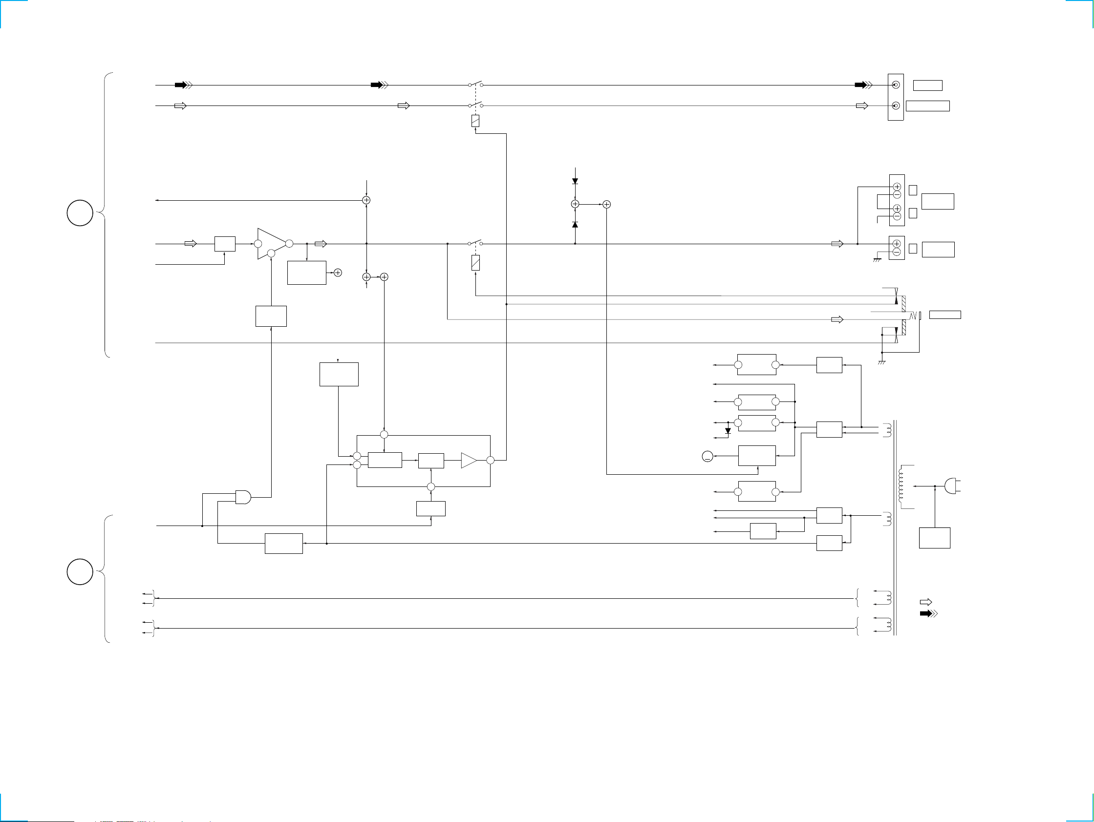
POWER SECTION
VIDEO
RY781
STR-VX500
J781
VIDEO OUT
C
MAIN
SECTION
S/W
L+R
L-CH
TA MUTE
MUTE
MUTE
Q181
POWER AMP
IC901
20
8
MUTE
SWITCH
Q901
15
OVER LOAD
DET
Q952
OVER LOAD
SWITCH
Q851
1
4
R-CH
R-CH
2
PROTECTOR
PROTECTOR
IC851
VCC ON
MUTE
RY751
SUPER WOOFER
R-CH
D761
D751
ST+10V
UNREG
+12V
+7V
+5.6V
D813
+5V
M901
M
6
FAN
MOTOR
ST+10V
3 1
REG
IC804
+7V REG
3
IC801
+5.6V REG
3
IC803
FAN MOTOR
REG
Q731,732
1
1
RECT
D810,811
+
RECT
D805-808
–
R-CH
R-CH
T901
POWER
TRANSFORMER
TB201
L
REAR
SPEAKER
R
TB751
FRONT
L
SPEAKER
J755
PHONES
B
MAIN
SECTION
16
POWER ON/OFF
AC1
AC2
VF1
VF2
D852,853
POWER ON
MUTE
Q852
7
SWITCH
Q853
-7V
+B
-B
VG
-7V REG
3
IC802
VG REG
Q801
2
+
RECT
D801
–
VOLTAGE
RECT
D802, 803
SELECTOR
S871
AC
IN
• R CH : Same as L ch
AC1
AC2
VF1
VF2
• SIGNAL PATH
: FM
: VIDEO (AV INPUT)
1111
Page 12
STR-VX500
d
THIS NOTE IS COMMON FOR PRINTED WIRING
BOARDS AND SCHEMATIC DIAGRAMS.
(In addition to this, the necessary note is printed
in each block.)
For schematic diagrams.
Note:
• All capacitors are in µF unless otherwise noted. pF: µµF
50 WV or less are not indicated except for electrolytics
and tantalums.
• All resistors are in Ω and 1/
specified.
¢
•
• 2 : nonflammable resistor.
• 1 : fusible resistor.
• C : panel designation.
• U : B+ Line.
• V : B– Line.
• H : adjustment for repair.
• Voltages and waveforms are dc with respect to ground
• Voltages are taken with a VOM (Input impedance 10 MΩ).
• Waveforms are taken with a oscilloscope.
• Circled numbers refer to waveforms.
• Signal path.
• Abbreviation
: internal component.
The components identified by mark ! or dotted
line with mark ! are critical for safety.
Replace only with part number specified.
under no-signal (detuned) conditions.
Voltage variations may be noted due to normal produc-
tion tolerances.
Voltage variations may be noted due to normal produc-
tion tolerances.
F : FM
f : AM
L : AUDIO (AV INPUT)
g : MD/VIDEO
i : VIDEO (AV INPUT)
E : PB (DECK A)
G : REC (DECK B)
J : CD
HK : Hong Kong model
SP : Singapore model
MY : Malaysia model
IA : Indonesia model
EA : Saudi Arabia model
4
W or less unless otherwise
For printed wiring boards.
Note:
• X : parts extracted from the component side.
• Y : parts extracted from the conductor side.
• p : parts mounted on the conductor side.
®
•
•
• b : Pattern from the side which enables seeing.
: Through hole.
¢
: internal component.
• Indication of transistor
C
Q
These are omitte
EB
C
EB
These are omitted
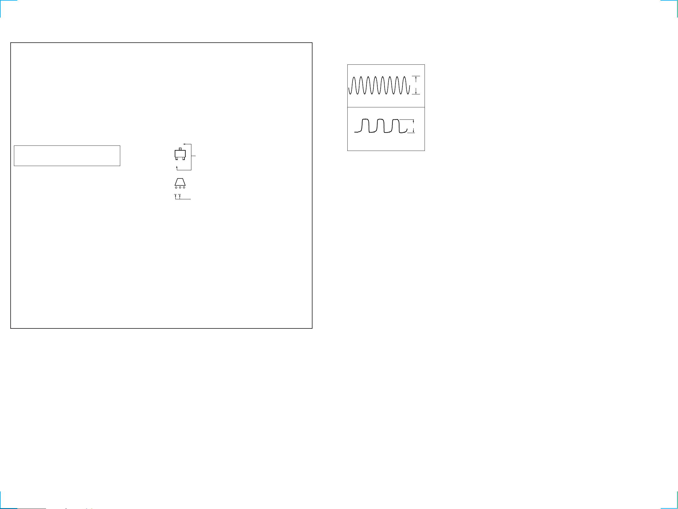
• Wavef orms
DISPLAY Section
1
5.5Vp-p
5MHz
IC501 0 X2
2
5Vp-p
32.768kHz
IC501 qd XT2
1212
Page 13
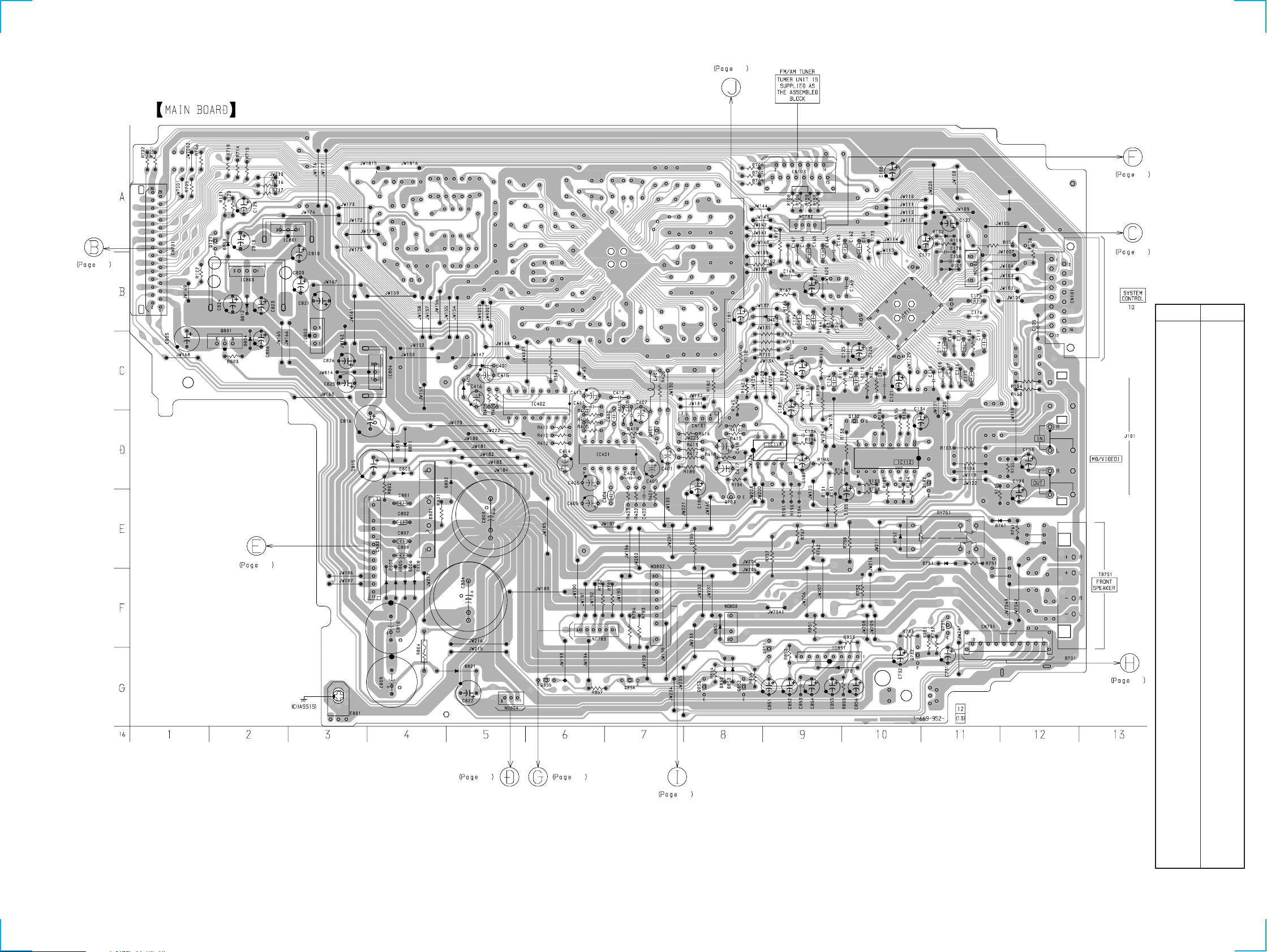
STR-VX500
4-3. PRINTED WIRING BOARD MAIN SECTION
19
22
• Refer to page 9 for Circuit Boards Location.
17
25
25
• Semiconductor
Location
HTC-VX500
Ref. No. Location
D101 B-11
D102 B-11
D131 E-9
D401 D-5
D402 D-5
D403 C-9
D751 F-11
D752 E-10
D761 E-12
D781 G-10
D801 E-4
D802 F-5
D803 E-4
D804 C-2
D805 F-4
D806 F-4
D807 F-4
D808 F-4
D810 E-4
D811 E-4
D812 C-2
D813 B-2
D851 F-8
D852 G-8
D853 G-8
21 21
IC111 C-10
IC112 E-10
IC113 E-9
IC401 E-7
IC402 D-6
IC801 B-2
IC802 C-3
BB
17
IC803 B-2
IC804 D-4
IC851 G-9
Q121 B-2
Q132 D-10
Q182 E-11
Q183 E-8
Q401 D-7
Q731 G-11
17
Q732 G-10
Q801 C-2
Q851 G-9
Q852 H-8
Q853 H-8
Q854 G-7
Q855 G-6
1313
Page 14
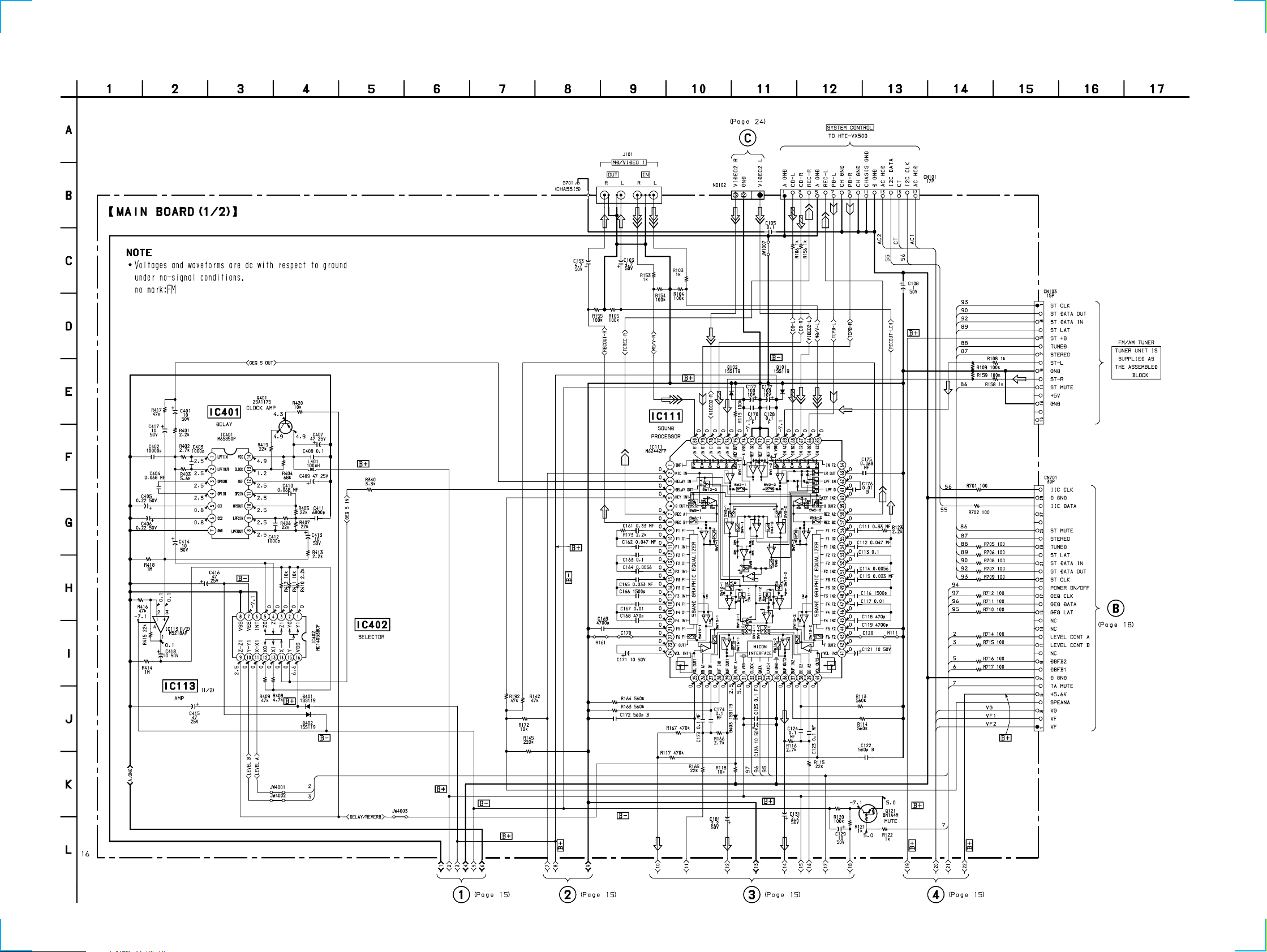
STR-VX500
4-4. SCHEMATIC DIAGRAM MAIN (1/2) SECTION
• Refer to page 27 for IC Block Diagrams.
1414
Page 15

STR-VX500
4-5. SCHEMATIC DIAGRAM MAIN (2/2) SECTION
• Refer to page 13 for Printed Wiring Board.
• Refer to page 27 for IC Block Diagrams.
The components identified by mark ! or dotted
line with mark ! are critical for safety.
Replace only with part number specified.
Q854
0.8
BN1F4M
R857
22k
0
0.1
Q855
2SC2958L
RELAY SWITCH
1515
Page 16

STR-VX500
4-6. SCHEMATIC DIAGRAM POWER AMP SECTION
The components identified by mark ! or dotted
line with mark ! are critical for safety.
Replace only with part number specified.
1616
Page 17

STR-VX500
4-7. PRINTED WIRING BOARD POWER AMP SECTION
13
• Refer to page 9 for Circuit Boards Location.
25
1717
Page 18

STR-VX500
4-8. SCHEMATIC DIAGRAM DISPLAY SECTION
MY,SP,IA,HK
MODEL
EA MODEL
• Refer to page 28 for IC Block Diagrams.
• Refer to page 12 for Waveform.
1818
Page 19

STR-VX500
4-9. PRINTED WIRING BOARD DISPLAY SECTION
13
• Refer to page 9 for Circuit Boards Location.
EA MODEL
MY,SP,IA,HK MODEL
• Semiconductor
Location
Ref. No. Location
D501 E-2
D502 D-3
D504 E-4
D505 F-4
D506 F-3
D507 F-3
D509 F-6
D511 D-1
D512 D-8
D513 D-7
D514 D-7
D515 D-7
D516 D-6
D517 D-6
D518 D-5
D519 D-5
D520 D-4
D521 D-5
D522 D-3
IC501 B-4
IC502 E-2
IC503 B-10
IC505 D-10
IC506 C-10
IC601 B-7
21
25
21
Q501 D-3
Q502 D-8
Q503 D-7
Q505 D-7
Q504 D-7
Q506 D-6
Q507 D-6
Q508 D-5
Q509 D-5
Q510 D-5
Q511 D-4
Q512 E-3
Q513 B-9
1919
Page 20

STR-VX500
4-10. SCHEMATIC DIAGRAM SLIDING PANEL SECTION
• Refer to page 28 for IC Block Diagrams.
2020
Page 21

STR-VX500
4-11. PRINTED WIRING BOARD SLIDING PANEL SECTION
• Refer to page 9 for Circuit Boards Location.
19
13
13
19
2121
Page 22

STR-VX500
4-12. PRINTED WIRING BOARD TRANS SECTION
• Refer to page 9 for Circuit Boards Location.
13
2222
Page 23

4-13. SCHEMATIC DIAGRAM TRANS SECTION
2.5A
2.5A
(Page 15)
T6.3AL
250V
STR-VX500
16
The components identified by mark ! or dotted
line with mark ! are critical for safety.
Replace only with part number specified.
23
Page 24

STR-VX500
4-14. SCHEMATIC DIAGRAM AV/MIC SECTION
• Refer to page 28 for IC Block Diagrams.
24
Page 25

STR-VX500
4-15. PRINTED WIRING BOARD AV/MIC SECTION
13
• Refer to page 9 for Circuit Boards Location.
13
25
Page 26

4-16. IC BLOCK DIAGRAMS
• MAIN BOARD
IC300 LV1041M
L-R RECT
R DET3
DC CUT1
DC CUT2
L+R RECT
VCS TH
VCS 1
VCS 2
VLR 2
VLR 1
VLR TH
L RECT
DC CUT4
R RECT
DC CUT3
L BPF3
R BPF2
R BPF1
S DC OUT
C DC OUT
R DC OUT
L DC OUT
V REF
VCC
C OUT
S OUT
R OUT
L OUT
GND
L IN
R IN
S IN
DELAY OUT
C VOL IN
DET
IREF
R OUT
R NF
L NF
L OUT
78
80
79
1
BPF
2
3
4
5
6
7
V REF
8
9
C
10
S
R
11
L
12
12
13
SW
P
B
P
B
S
NF
14
15
16
17
18
19
20
20
21
22
23
24
77
76
RECT
R
L
P
B
S
C VOL OUT
LOGIC
FF
VCA VCA
VCA VCA VCA VCA
P
B
P
B
P
S
B
P
B
S
2928
C OP IN
RECT
STRIM
P
B
P
B
L
R
R
L
MASTER
VOL
26
25
27
VCC
7475
MODE
P
B
30
GND
C OP NF
73
LOGIC LOGIC
S
P
C
72
VCA VCA
C MODE
STRIM
VOL/
MUTE
P
BB
LR
31
32
33
VOL REF
C OP OUT
S OP OUT
71
LOGIC
FF
DC
CUT
S
34
35
S OP IN
S OP NF
P
B
P
B
CH
CONTROL
P
B
C
D
MASTER VOL
S VOL OUT
6970
IN
FILTER
SRAM
PCM
CONTROL
PCM
3736
OP VREF
FILTER
68
RECT
RECT
B NR
OUT
38
VOL
BPF
CONTROL
NOISE
FILTER
NOISE
GEN
P
B
S VOL IN
VOL
67
66
65
64
L BPF2
BPF
63
L BPF1
62
DC CUT
61
60
59
58
57
56
55
54
53
52
51
50
49
48
47
46
45
44
43
42
41
RT IN
LT IN
DC CUT
C MODE
GND
NS BPF1
NS BPF2
OSC
CLK
DATA
ENABLE
DATA
CLK
ENABLE2
VSS
OSC
OSC
VDD
A/D
NS
D/A
DC CUT
DATA
DECODER
VDD
39
S OUT
R
L
OSC
IEV
40
26
Page 27

IC401 M65850P
1
LPF1IN
VCC
1/2 VCC
AUTO
RESET
LPF1
CLOCK
REF
OSCILLATOR
CLOCK
MAIN
RESET
CONTROL
D1
DO0
A/D
2 345 6 7
OP1IN
OP1OUT
LPF1OUT
DO1
CC1
OP2IN
D/A
MO
MI
OP2OUT
LPF2IN
20KBIT
CC2
LPF2OUT
891014 13 12 11
LPF2
SRAM
GND
IC851 µPC1237HA
OVER LOAD DET
V
CC
OFFSET DET
LATCH/
AUTORESET
AC OFF
DET
1 2 3 4 5 6 7 8
F/F
MUTE
ON
V
CC
27
Page 28

• PANEL BOARD
IC505 µPD4053BC
1
B1
B0
2
C1
3
C.COM
4
5
CO
6
INH
7
VEE
8
VSS
OPEN
OPEN
OPEN
IC506 BA3833F-E2
VDD
16
RESET
B.COM
15
14
A.COM
13
A1
A0
12
11
A
10
B
C
9
C
PREF
LINE
NF
LINE
IN
GND
BIAS
1
REFFERENCE
2
CURRENT
3
4
5
6
Bias
C
7
NC
8
NC
9
NC
RESET
BPF
BPF DET
BPF DET
BPF DET
DET
DET
18
RESET
17
f01
16
f02
15
f03
14
f04
13
f
12
VCC
11
NC
10
NC
• MOTOR BOARD
IC891 LB1641
T.S.D O.C.P
MOTOR
DRIVE
FWD/REV/STOP
CONTROL LOGIC
2 3
1
GND
DRIVE
MOTOR
NOISE
FILTER
5 6 7 8 9 10
4
VCC 1
FWD.IN
REV.IN
CLAMP
VCC 2
NOISE
FILTER
MOTOR
DRIVE
DRIVE
MOTOR
• MIC/ECHO BOARD
IC6002 M65850P
1
LPF1IN
VCC
1/2 VCC
AUTO
RESET
LPF1
CLOCK
OSCILLATOR
CLOCK
MAIN
RESET
CONTROL
D1
A/D
2 345 6 7
OP1OUT
LPF1OUT
REF
OP1IN
DO0
DO1
CC1
OP2IN
D/A
MO
MI
OP2OUT
LPF2IN
20KBIT
CC2
LPF2OUT
891014 13 12 11
LPF2
SRAM
GND
28
Page 29

4-17. IC PIN FUNCTION
• IC501 SYSTEM CONTROL (uPD780016AYGF-025-3BA) (PANEL BOARD)
Pin No.
1
2
3
4
5
6
7
8
9
10
11
12
13
14
15
16
17
18
19
20
21
22
23
24
25
26
27
28
29
30
31
32
33
34
35
36
37
38
39
40
Pin Name
CLK
LEVEL A
LEVEL B
PROLOGIC RLY
DBFB B2
DBFB B1
TA MUTE
GND
TEST
X2
X1
VDD
XT2
XT1
RESET
RDS CLK
RDS DATA
VOL A
VOL B
JOG A
JOG B
SPEANA CONT
VDD
A VDD
VACS
SPEANA0
SPEANA1
KEY0
KEY1
KEY2
KEY3
ACCUT
A VSS
GND
FL DATA
FL CLK
FL LAT
FL RESET
GND
VSS
I/O
—
Not used
O
Surround level A signal output
O
Surround level B signal output
—
Not used
O
DBFB level 2 signal output
O
DBFB level 1 signal output
O
Mute signal output
—
Ground
—
Test terminal (Connected to ground)
O
X’ tal (5MHz)
I
—
Power supply (+5V)
O
X’ tal (32kHz)
I
I
Reset signal input
I
RDS clock input
I
RDS data input
I
Rotary encoder (VOLUME) pulse input
I
I
Rotary encoder (MULTI JOG STATION) pulse input
I
O
Spectrum analyzer control output
—
Power supply (+5V)
—
Analog power supply (+5V)
I
Audio input for VACS control
I
Spectrum analyzer data input
I
I
I
Key data input
I
I
I
Back up signal input
—
Analog ground
—
Ground
O
FL data output
O
FL clock output
O
FL latch output
O
FL reset output
—
Ground
—
Ground
Description
• Abbreviation
FL : Fluorescent indicator tube
29
Page 30

Pin No.
41
42
43
44
45
46
47
48
49
50
51
52
53
54
55
56
57
58
59
60
61
62
63
64
65
66
67
68
69
70
71
72
73
74
75
76
77
78
79
80
Pin Name
AV IN
SENSOR IN
SIRCS IN
SPEANE RST
GND
GND
GND
GND
SOFT
SEN
MOVIE A
MOVIE G
MUSIC A
MUSIC G
I2C DATA
I2C CLK
GAME A
GAME G
PLACE A
PLACE G
PFILE A
PFILE G
GROOVE
+/–
JOG
ENTER
EFECT
KEYCON G
KEYCON A
NON STOP
VSS
DELAY
REVER B
SUFFIX0
SUFFIX1
SUFFIX2
SUFFIX3
WJ1/WJ3
GND
VCD
I/O
I
AV INPUT (VIDEO 2) switch input
I
Sliding (panel) sensor signal input
I
Remote sensor signal input
O
Spectrum analyzer reset output
—
—
Ground
—
—
O
Soft test terminal
O
Audio indicator output
O
O
LED driver output
O
O
I/O
Serial data input/output
I/O
Serial clock input/output
O
O
O
O
O
O
LED driver output
O
O
O
O
O
—
Not used
—
O
LED driver output
—
Ground
O
LED driver output
O
I
I
Destination terminal
I
I
I
Model select terminal
—
Ground
I
VCD select terminal “L”: NON-VCD (Connected to ground)
Description
30
Page 31

Pin No.
81
82
83
84
85
86
87
88
89
90
91
92
93
94
95
96
97
98
99
100
Pin Name
GND
MOTOR1
MOTOR2
PANEL OPEN
PANEL CLOSE
ST. MUTE
STEREO
TUNED
LAT
DATA IN
PCL OUT
DATA OUT
CLK
POWER ON/OFF
GEQ LAT
GEQ DATA
GEQ CLK
LAT1
LAT2
DAT A
I/O
—
Ground
O
Panel motor control output
O
O
Panel open switch output
O
Panel close switch output
O
ST mute signal output
I
Stereo detection input for tuner
I
Tuner detection input for tuner
O
Tuner PLL latch output
I
Tuner PLL data input
O
Sub clock output
O
Tuner PLL data output
O
Tuner clock output
O
Power on/off control output
O
GEQ latch output
O
GEQ data output
O
GEQ clock output
—
—
Not used
—
Description
• Abbreviation
GEQ : Graphic Equalizer
PLL : Phase Locked Loop
31
Page 32

NOTE:
• -XX, -X mean standardized parts, so they may
have some differences from the original one.
• Items marked “*” are not stocked since they
are seldom required for routine service. Some
delay should be anticipated when ordering these
items.
• The mechanical parts with no reference number
in the exploded views are not supplied.
• Hardware (# mark) list and accessories and
packing materials are given in the last of this
parts list.
• Abbrevation
HK : Hong Kong model
SP : Singapore model
MY : Malaysia model
IA : Indonesia model
EA : Saudi Arabia model
5-1. CASE AND SLIDING PANEL SECTION
SECTION 5
EXPLODED VIEWS
The components identified by mark ! or
dotted line with mark ! are critical for safety.
Replace only with part number specified.
Supplied with
S653
10
#2
7
10
#1
Slide mechanism
11
6
5
11
#1
10
4
10
11
11
9
#2
#2
1
Supplied with
2
S652
3
11
Front panel
#2
A
8
A
#2
11
#2
Ref. No. Part No. Description Remarks Ref. No. Part No. Description Remarks
1 4-219-918-01 KNOB (JOG)
2 X-4951-659-1 KNOB (VOLUME) ASSY
3 1-773-125-11 WIRE (FLAT TYPE) (19 CORE)
4 X-4951-775-1 SLIDING PANEL SUB ASSY
* 5 A-4414-709-A LOADING PANEL BOARD, COMPLETE
(EA,HK,MY,SP)
* 5 A-4414-736-A LOADING PANEL BOARD, COMPLETE (IA)
6 4-900-855-01 COVER
* 7 4-900-858-01 UPPER CASE
8 4-812-134-00 RIVET (DIA. 3.5), NYLON
* 9 4-900-852-01 HOLDER LEVEL
10 3-363-099-01 SCREW (CASE 3 TP2)
11 4-951-620-11 SCREW (2.6 × 10), +BVTP
32
Page 33

5-2. FRONT PANEL SECTION
not supplied
53
54
57
60
58
65
58
IC504
62
63
FL601
58
58
58
62
61
64
58
58
58
58
66
59
not supplied
51
68
67
Ref. No. Part No. Description Remarks Ref. No. Part No. Description Remarks
51 X-4951-776-1 FRONT PANEL ASSY
53 X-4951-665-1 ESCUTCHEON (L) ASSY
54 X-4949-994-1 ESCUTCHEON (EQ) ASSY
57 4-962-708-11 EMBLEM (4-A), SONY
58 4-951-620-01 SCREW (2.6 × 8), +BVTP
* 59 A-4414-708-A MIC/ECHO BOARD, COMPLETE (EA,HK,MY,SP)
* 59 A-4414-724-A MIC/ECHO BOARD, COMPLETE (IA)
* 60 1-669-960-11 HEADPHONE BOARD
* 61 A-4417-072-A PANELBOARD, COMPLETE (HK, MY, SP)
* 61 A-4414-737-A PANEL BOARD,COMPLETE (IA)
* 61 A-4426-837-A PANEL BOARD,COMPLETE (EA)
* 62 4-932-810-11 CUSHION (FL)
* 63 4-900-849-01 HOLDER (FL)
* 64 1-669-957-11 FRONT AV BOARD
65 4-900-845-01 BRACKET SLIDER
* 66 1-669-964-11 DETECTOR BOARD
67 4-900-868-11 KNOB (CENTER)
68 4-900-867-11 KNOB (CONTROL)
FL601 1-517-775-11 INDICATOR TUBE, FLUORESCENT
IC504 8-719-070-85 IC KU381-4
33
Page 34

5-3. SLIDE MECHANISM SECTION
102
101
102
103
102
108
102
106
105
111
M891
107
104
#3
112
109
113
102
110
106
102
Ref. No. Part No. Description Remarks Ref. No. Part No. Description Remarks
101 4-900-844-01 LEVEL SLIDER
102 4-951-620-01 SCREW (2.6X8), +BVTP
103 X-4950-394-1 HOLDER (L) ASSY
104 X-4950-395-1 HOLDER (R) ASSY
* 105 4-210-042-01 BRACKET (SENSOR)
106 4-900-846-01 GEAR (1)
107 4-900-862-01 SHAFT CENTER
108 4-900-864-01 BRACKET TOP
109 4-900-847-01 GEAR (2)
110 3-344-059-01 BELT (L)
* 111 1-669-965-11 MOTOR BOARD
112 4-212-966-01 SPRING LAVEL
113 4-212-965-01 STOPPER LAVEL
M891 A-4660-926-A MOTOR (CDM) ASSY
34
Page 35

2
5-4. CIRCUIT BOARDS AND BACK PANEL SECTION
#5
T901
155
#5
156
#5
#5
154
#4
#2
#1
IA MODEL
160
not supplied
159
153
#1
#2
161
#2
160
HK MODEL
152
161
M901
EA, SP, MY MODEL
160
157
161
#2
#2
#2
#
#2
#6
#1
B
not supplied
A
#2
158
B
151
A
Ref. No. Part No. Description Remarks Ref. No. Part No. Description Remarks
* 151 A-4419-951-A MAIN BOARD, COMPLETE (EA,HK,MY,SP)
* 151 A-4426-429-A MAIN BOARD, COMPLETE (IA)
* 152 1-669-963-11 SURR SPK BOARD
153 1-233-546-32 ENCAPSULATED COMPONENT (AM/FM TUNER)
* 154 A-4419-954-A POWER AMP BOARD, COMPLETE
(EA,HK,MY,SP)
* 154 A-4426-428-A POWER AMP BOARD, COMPLETE (IA)
* 155 1-669-954-12 SECONDARY BOARD
* 156 1-669-953-11 PRIMARY BOARD
* 157 4-900-848-51 BACK PANEL
158 4-970-381-11 FOOT (REAR)
* 159 3-703-244-00 BUSHING (2104), CORD
! 160 1-777-071-21 CORD, POWER (EA,HK,MY,SP)
! 160 1-782-315-11 CORD, POWER (IA)
! 161 1-569-007-11 ADAPTOR, CONVERSION 2P (IA)
! 161 1-569-008-21 ADAPTOR, CONVERSION 2P (EA,MY,SP)
! 161 1-770-019-11 ADAPTOR, CONVERSION PLUG 3P (HK)
M901 1-763-372-11 FAN, DC
! T901 1-433-932-11 TRANSFORMER, POWER
The components identified by mark ! or dotted
line with mark ! are critical for safety.
Replace only with part number specified.
35
Page 36

DETECTOR FRONT AV
SECTION 6
HEADPHONE LOADING PANEL
NOTE:
• Due to standardization, replacements in the
parts list may be different from the parts
specified in the diagrams or the components
used on the set.
• -XX, -X mean standardized parts, so they
may have some difference from the original
one.
• Items marked “*” are not stocked since they
are seldom required for routine service.
Some delay should be anticipated when
ordering these items.
• CAPACITORS:
uF: µF
Ref. No. Part No. Description Remarks Ref. No. Part No. Description Remarks
* 1-669-964-11 DETECTOR BOARD
***************
• RESISTORS
All resistors are in ohms.
METAL: metal-film resistor
METAL OXIDE: Metal Oxide-film resistor
F: nonflammable
• COILS
uH: µH
• SEMICONDUCTORS
In each case, u: µ, for example:
uA...: µA... , uPA... , µPA... ,
uPB... , µPB... , uPC... , µPC... ,
uPD..., µPD...
ELECTRICAL PARTS LIST
When indicating parts by reference number,
please include the board name.
The components identified by mark ! or
dotted line with mark ! are critical for safety.
Replace only with part number specified.
• Abbrevation
HK : Hong Kong model
SP : Singapore model
MY : Malaysia model
IA : Indonesia model
EA : Saudi Arabia model
* 1-669-960-11 HEADPHONE BOARD
*****************
< CONNECTOR >
* CN505 1-568-941-11 PIN, CONNECTOR 3P
< SWITCH >
S892 1-571-300-21 SWITCH, ROTARY (OPEN/CLOSE)
************************************************************
* 1-669-957-11 FRONT AV BOARD
***************
< CAPACITOR >
C6301 1-162-282-31 CERAMIC 100PF 10% 50V
C6302 1-162-282-31 CERAMIC 100PF 10% 50V
C6303 1-162-306-11 CERAMIC 0.01uF 30% 16V
C6304 1-164-159-11 CERAMIC 0.1uF 50V
< CONNECTOR >
* CN6301 1-564-520-11 PLUG, CONNECTOR 5P
* CN6302 1-560-666-00 PIN, CONNECTOR 3P
< DIODE >
D6301 8-719-911-19 DIODE 1SS133T-72
D6302 8-719-911-19 DIODE 1SS133T-72
D6303 8-719-911-19 DIODE 1SS133T-72
< JACK >
J6301 1-784-901-11 JACK, PIN 3P (AV INPUT)
< CAPACITOR >
C790 1-162-306-11 CERAMIC 0.01uF 30% 16V
C791 1-162-294-31 CERAMIC 0.001uF 10% 50V
C792 1-162-294-31 CERAMIC 0.001uF 10% 50V
< CONNECTOR >
* CN790 1-568-944-11 PIN, CONNECTOR 6P
< TERMINAL >
* G790 1-537-738-21 TERMINAL, EARTH
< JACK >
J755 1-774-728-41 JACK (PHONES)(EA,HK,MY,SP)
J755 1-770-226-11 JACK (LARGE TYPE) (PHONES)(IA)
************************************************************
* A-4414-709-A LOADING PANEL BOARD, COMPLETE
(EA,HK,MY,SP)
**************************************
* A-4414-736-A LOADING PANEL BOARD, COMPLETE (IA)
*********************************
< CAPACITOR >
C626 1-124-584-00 ELECT 100uF 20% 10V
C627 1-162-306-11 CERAMIC 0.01uF 30% 16V
C628 1-162-306-11 CERAMIC 0.01uF 30% 16V
C629 1-162-306-11 CERAMIC 0.01uF 30% 16V
C630 1-162-306-11 CERAMIC 0.01uF 30% 16V
< COIL >
L6301 1-412-473-21 INDUCTOR 0uH
< TRANSISTOR >
Q6301 8-729-900-36 TRANSISTOR BA1F4M-TP
< RESISTOR >
R6301 1-249-417-11 CARBON 1K 5% 1/4W F
R6302 1-249-417-11 CARBON 1K 5% 1/4W F
R6303 1-249-441-11 CARBON 100K 5% 1/4W
R6304 1-249-441-11 CARBON 100K 5% 1/4W
R6305 1-249-425-11 CARBON 4.7K 5% 1/4W F
R6306 1-249-425-11 CARBON 4.7K 5% 1/4W F
R6307 1-249-425-11 CARBON 4.7K 5% 1/4W F
R6308 1-249-429-11 CARBON 10K 5% 1/4W
************************************************************
36
< CONNECTOR >
CN630 1-569-308-11 SOCKET, CONNECTOR (L TYRE) 19P
< DIODE >
D631 8-719-046-39 DIODE SEL5821A-TP15 (GROOVE)
D632 8-719-046-44 DIODE SEL5221S-TP15 (REW)
D633 8-719-058-04 DIODE SEL5223S-TP15 (MULTI JOG STATION)
D634 8-719-046-44 DIODE SEL5221S-TP15 (ENTER/NEXT)
D635 8-719-046-44 DIODE SEL5221S-TP15 (EFFECT ON/OFF)
D636 8-719-046-43 DIODE SEL5421E-TP15 (KEY CONTOROL #)
D637 8-719-046-39 DIODE SEL5821A-TP15 (KEY CONTOROL b)
D638 8-719-046-44 DIODE SEL5221S-TP15 (NON-STOP)
D639 8-719-046-44 DIODE SEL5221S-TP15 (DSP)
D640 8-719-046-44 DIODE SEL5221S-TP15 (PROLOGIC)
D641 8-719-046-44 DIODE SEL5221S-TP15 (FF)
D642 8-719-058-04 DIODE SEL5223S-TP15 (MULTI JOG STATION)
Page 37

LOADING PANEL MAIN
Ref. No. Part No. Description Remarks Ref. No. Part No. Description Remarks
< TRANSISTOR >
< SWITCH >
Q531 8-729-900-80 TRANSISTOR BA1A4M-TP
Q532 8-729-900-80 TRANSISTOR BA1A4M-TP
Q533 8-729-900-80 TRANSISTOR BA1A4M-TP
Q534 8-729-900-80 TRANSISTOR BA1A4M-TP
Q535 8-729-900-80 TRANSISTOR BA1A4M-TP
Q536 8-729-900-80 TRANSISTOR BA1A4M-TP
Q537 8-729-900-80 TRANSISTOR BA1A4M-TP
Q538 8-729-900-80 TRANSISTOR BA1A4M-TP
Q539 8-729-900-80 TRANSISTOR BA1A4M-TP
Q540 8-729-900-80 TRANSISTOR BA1A4M-TP
< RESISTOR >
R632 1-249-407-11 CARBON 150 5% 1/4W F
R633 1-249-403-11 CARBON 68 5% 1/4W F
R634 1-249-407-11 CARBON 150 5% 1/4W F
R635 1-249-413-11 CARBON 470 5% 1/4W F
R636 1-249-410-11 CARBON 270 5% 1/4W F
R637 1-249-410-11 CARBON 270 5% 1/4W F
R638 1-249-413-11 CARBON 470 5% 1/4W F
R639 1-249-413-11 CARBON 470 5% 1/4W F
R640 1-249-413-11 CARBON 470 5% 1/4W F
R641 1-247-807-31 CARBON 100 5% 1/4W
R642 1-249-407-11 CARBON 150 5% 1/4W F
R643 1-249-409-11 CARBON 220 5% 1/4W F
R644 1-249-411-11 CARBON 330 5% 1/4W
R645 1-249-411-11 CARBON 330 5% 1/4W
R646 1-249-413-11 CARBON 470 5% 1/4W F
R647 1-249-415-11 CARBON 680 5% 1/4W F
R648 1-249-417-11 CARBON 1K 5% 1/4W F
R649 1-249-419-11 CARBON 1.5K 5% 1/4W F
R650 1-249-421-11 CARBON 2.2K 5% 1/4W F
R651 1-247-843-11 CARBON 3.3K 5% 1/4W
S631 1-762-751-11 SWITCH, TACTILE (REW)
S632 1-762-751-11 SWITCH, TACTILE (GAME)
S633 1-762-751-11 SWITCH, TACTILE (MUSIC)
S634 1-762-751-11 SWITCH, TACTILE (MOVIE)
S635 1-762-751-11 SWITCH, TACTILE (PROLOGIC)
S636 1-762-751-11 SWITCH, TACTILE (CD REPEAT)
S637 1-762-751-11 SWITCH, TACTILE (FLASH)
S638 1-762-751-11 SWITCH, TACTILE (DSP)
S639 1-762-751-11 SWITCH, TACTILE (CD PLAY MODE)
S640 1-762-751-11 SWITCH, TACTILE (CD EDIT)
S641 1-762-751-11 SWITCH, TACTILE (NON-STOP)
S642 1-762-751-11 SWITCH, TACTILE (DBFB)
S643 1-762-751-11 SWITCH, TACTILE (ENTER/NEXT)
S644 1-762-751-11 SWITCH, TACTILE (FF)
S645 1-762-751-11 SWITCH, TACTILE (GROOVE)
S646 1-762-751-11 SWITCH, TACTILE (KEY CONTORL #)
S647 1-762-751-11 SWITCH, TACTILE (KEY CONTORL b)
S648 1-762-751-11 SWITCH, TACTILE (EFFECT ON/OFF)
S649 1-762-751-11 SWITCH, TACTILE (P FILE)
S650 1-762-751-11 SWITCH, TACTILE (PLACE)
S651 1-762-751-11 SWITCH, TACTILE (LOOP)
S652 1-473-392-11 ENCODER, ROTARY (VOLUME)
S653 1-473-393-11 ENCODER, ROTARY (MULTI JOG STATION)
************************************************************
A-4419-951-A MAIN BOARD, COMPLETE (EA,HK,MY,SP)
*********************************
A-4426-429-A MAIN BOARD, COMPLETE (IA)
************************
7-685-872-09 SCREW +BVTT 3 × 8 (S)
< CAPACITOR >
R652 1-249-417-11 CARBON 1K 5% 1/4W F
R653 1-247-807-31 CARBON 100 5% 1/4W
R654 1-249-407-11 CARBON 150 5% 1/4W F
R655 1-249-409-11 CARBON 220 5% 1/4W F
R656 1-249-411-11 CARBON 330 5% 1/4W
R657 1-249-411-11 CARBON 330 5% 1/4W
R658 1-249-413-11 CARBON 470 5% 1/4W F
R659 1-249-415-11 CARBON 680 5% 1/4W F
R660 1-249-429-11 CARBON 10K 5% 1/4W
R661 1-249-429-11 CARBON 10K 5% 1/4W
R662 1-249-429-11 CARBON 10K 5% 1/4W
R663 1-249-429-11 CARBON 10K 5% 1/4W
R665 1-247-843-11 CARBON 3.3K 5% 1/4W
R666 1-247-843-11 CARBON 3.3K 5% 1/4W
R671 1-247-807-31 CARBON 100 5% 1/4W
R672 1-247-807-31 CARBON 100 5% 1/4W
R673 1-247-807-31 CARBON 100 5% 1/4W
R674 1-247-807-31 CARBON 100 5% 1/4W
R675 1-247-807-31 CARBON 100 5% 1/4W
R676 1-247-807-31 CARBON 100 5% 1/4W
R677 1-247-807-31 CARBON 100 5% 1/4W
R678 1-247-807-31 CARBON 100 5% 1/4W
R679 1-247-807-31 CARBON 100 5% 1/4W
R680 1-247-807-31 CARBON 100 5% 1/4W
C103 1-126-963-11 ELECT 4.7uF 20% 50V
C105 1-164-159-11 CERAMIC 0.1uF 50V
C108 1-126-160-11 ELECT 1uF 20% 50V
C111 1-136-171-00 FILM 0.33uF 5% 50V
C112 1-136-161-00 FILM 0.047uF 5% 50V
C113 1-164-159-11 CERAMIC 0.1uF 50V
C114 1-130-480-00 MYLAR 0.0056uF 5% 50V
C115 1-136-159-00 FILM 0.033uF 5% 50V
C116 1-162-301-11 CERAMIC 0.0015uF 20% 16V
C117 1-162-306-11 CERAMIC 0.01uF 30% 16V
C118 1-162-290-31 CERAMIC 470PF 10% 50V
C119 1-162-600-11 CERAMIC 0.0047uF 30% 16V
C121 1-126-964-11 ELECT 10uF 20% 50V
C122 1-162-291-31 CERAMIC 560PF 10% 50V
C123 1-136-165-00 FILM 0.1uF 5% 50V
C124 1-136-165-00 FILM 0.1uF 5% 50V
C125 1-164-159-11 CERAMIC 0.1uF 50V
C126 1-126-964-11 ELECT 10uF 20% 50V
C127 1-104-665-11 ELECT 100uF 20% 10V
C128 1-164-159-11 CERAMIC 0.1uF 50V
C129 1-126-964-11 ELECT 10uF 20% 50V
C131 1-126-961-11 ELECT 2.2uF 20% 50V
C134 1-104-664-11 ELECT 47uF 20% 25V
C135 1-126-959-11 ELECT 0.47uF 20% 50V
C153 1-126-963-11 ELECT 4.7uF 20% 50V
37
Page 38

MAIN
Ref. No. Part No. Description Remarks Ref. No. Part No. Description Remarks
C161 1-136-171-00 FILM 0.33uF 5% 50V
C162 1-136-161-00 FILM 0.047uF 5% 50V
C163 1-164-159-11 CERAMIC 0.1uF 50V
C164 1-130-480-00 MYLAR 0.0056uF 5% 50V
C165 1-136-159-00 FILM 0.033uF 5% 50V
C818 1-126-959-11 ELECT 0.47uF 20% 50V
C819 1-104-664-11 ELECT 47uF 20% 25V
C820 1-126-959-11 ELECT 0.47uF 20% 50V
C821 1-104-664-11 ELECT 47uF 20% 25V
C822 1-126-940-11 ELECT 330uF 20% 25V
C166 1-162-301-11 CERAMIC 0.0015uF 20% 16V
C167 1-162-306-11 CERAMIC 0.01uF 30% 16V
C168 1-162-290-31 CERAMIC 470PF 10% 50V
C169 1-162-600-11 CERAMIC 0.0047uF 30% 16V
C171 1-126-964-11 ELECT 10uF 20% 50V
C172 1-162-291-31 CERAMIC 560PF 10% 50V
C173 1-136-165-00 FILM 0.1uF 5% 50V
C174 1-136-165-00 FILM 0.1uF 5% 50V
C175 1-136-495-11 FILM 0.068uF 5% 50V
C176 1-162-306-11 CERAMIC 0.01uF 30% 16V
C177 1-104-665-11 ELECT 100uF 20% 10V
C178 1-164-159-11 CERAMIC 0.1uF 50V
C181 1-126-961-11 ELECT 2.2uF 20% 50V
C183 1-126-960-11 ELECT 1uF 20% 50V
C184 1-162-303-11 CERAMIC 0.0033uF 30% 16V
C186 1-162-292-31 CERAMIC 680PF 10% 50V
C187 1-126-961-11 ELECT 2.2uF 20% 50V
C188 1-126-960-11 ELECT 1uF 20% 50V
C401 1-126-964-11 ELECT 10uF 20% 50V
C402 1-162-306-11 CERAMIC 0.01uF 30% 16V
C403 1-162-294-31 CERAMIC 0.001uF 10% 50V
C404 1-136-495-11 FILM 0.068uF 5% 50V
C405 1-126-957-11 ELECT 0.22uF 20% 50V
C406 1-126-957-11 ELECT 0.22uF 20% 50V
C407 1-104-664-11 ELECT 47uF 20% 25V
C823 1-126-960-11 ELECT 1uF 20% 50V
C824 1-104-665-11 ELECT 100uF 20% 10V
C825 1-126-959-11 ELECT 0.47uF 20% 50V
C826 1-104-664-11 ELECT 47uF 20% 25V
C851 1-126-964-11 ELECT 10uF 20% 50V
C852 1-104-665-11 ELECT 100uF 20% 10V
C853 1-164-159-11 CERAMIC 0.1uF 50V
C854 1-126-961-11 ELECT 2.2uF 20% 50V
C855 1-126-934-11 ELECT 220uF 20% 10V
C856 1-104-665-11 ELECT 100uF 20% 10V
< CONNECTOR >
* CN101 1-764-017-21 HOUSING,CONNECTOR(PC BOARD)17P
CN103 1-774-289-11 PIN, CONNECTOR (PC BOARD) 15P
* CN131 1-564-507-11 PLUG, CONNECTOR 4P
CN701 1-778-311-11 SOCKET, CONNECTOR(PC BOARD)30P
* CN731 1-569-496-11 SOCKET, CONNECTOR 10P
CN801 1-691-773-11 PLUG (MICRO CONNECTOR) 11P
< DIODE >
D101 8-719-911-19 DIODE 1SS133T-72
D102 8-719-911-19 DIODE 1SS133T-72
D131 8-719-911-19 DIODE 1SS133T-72
D401 8-719-911-19 DIODE 1SS133T-72
D402 8-719-911-19 DIODE 1SS133T-72
C408 1-164-159-11 CERAMIC 0.1uF 50V
C409 1-104-664-11 ELECT 47uF 20% 25V
C410 1-136-495-11 FILM 0.068uF 5% 50V
C411 1-162-305-11 CERAMIC 0.0068uF 20% 16V
C412 1-162-294-31 CERAMIC 0.001uF 10% 50V
C413 1-126-964-11 ELECT 10uF 20% 50V
C414 1-126-964-11 ELECT 10uF 20% 50V
C415 1-104-664-11 ELECT 47uF 20% 25V
C416 1-104-664-11 ELECT 47uF 20% 25V
C417 1-126-964-11 ELECT 10uF 20% 50V
C418 1-126-964-11 ELECT 10uF 20% 50V
C731 1-104-664-11 ELECT 47uF 20% 25V
C732 1-126-964-11 ELECT 10uF 20% 50V
C801 1-136-165-00 FILM 0.1uF 5% 50V
C802 1-136-165-00 FILM 0.1uF 5% 50V
C803 1-128-493-11 ELECT 4700uF 20% 71V
C804 1-128-493-11 ELECT 4700uF 20% 71V
C805 1-126-948-11 ELECT 100uF 20% 35V
C806 1-126-964-11 ELECT 10uF 20% 50V
C807 1-136-165-00 FILM 0.1uF 5% 50V
C808 1-136-165-00 FILM 0.1uF 5% 50V
C809 1-126-943-11 ELECT 2200uF 20% 25V
C810 1-126-943-11 ELECT 2200uF 20% 25V
C815 1-126-940-11 ELECT 330uF 20% 25V
C816 1-126-951-11 ELECT 470uF 20% 35V
D403 8-719-911-19 DIODE 1SS133T-72
D751 8-719-911-19 DIODE 1SS133T-72
D752 8-719-911-19 DIODE 1SS133T-72
D761 8-719-911-19 DIODE 1SS133T-72
D781 8-719-024-99 DIODE 11ES2-NTA2B
D801 8-719-302-38 DIODE RBV-602-01
D802 8-719-911-19 DIODE 1SS133T-72
D803 8-719-911-19 DIODE 1SS133T-72
D804 8-719-934-22 DIODE HZS30-2LTA
D805 8-719-024-99 DIODE 11ES2-NTA2B
D806 8-719-024-99 DIODE 11ES2-NTA2B
D807 8-719-024-99 DIODE 11ES2-NTA2B
D808 8-719-024-99 DIODE 11ES2-NTA2B
D810 8-719-024-99 DIODE 11ES2-NTA2B
D811 8-719-024-99 DIODE 11ES2-NTA2B
D812 8-719-911-19 DIODE 1SS133T-72
D813 8-719-024-99 DIODE 11ES2-NTA2B
D821 8-719-024-99 DIODE 11ES2-NTA2B
D851 8-719-911-19 DIODE 1SS133T-72
D852 8-719-911-19 DIODE 1SS133T-72
D853 8-719-911-19 DIODE 1SS133T-72
< TERMINAL >
* E801 1-537-738-21 TERMINAL, EARTH
38
Page 39

MAIN
Ref. No. Part No. Description Remarks Ref. No. Part No. Description Remarks
< IC >
IC111 8-759-495-24 IC M62442FP-TP
IC112 8-759-000-48 IC MC14052BCP
IC113 8-759-634-51 IC M5218AP
IC401 8-759-450-96 IC M65850P
IC402 8-759-140-53 IC MC14053BCP
IC801 8-759-604-86 IC M5F7807L
IC802 8-759-604-90 IC M5F7907L
IC803 8-759-231-53 IC M5F7805L
IC804 8-759-604-32 IC M5F7810L
IC851 8-759-111-68 IC uPC1237HA
< JACK >
J101 1-770-613-11 JACK, PIN 4P (MD/VIDEO 1)
R136 1-247-883-00 CARBON 150K 5% 1/4W
R138 1-249-437-11 CARBON 47K 5% 1/4W
R139 1-247-903-00 CARBON 1M 5% 1/4W
R140 1-249-441-11 CARBON 100K 5% 1/4W
R141 1-249-418-11 CARBON 1.2K 5% 1/4W F
R142 1-249-437-11 CARBON 47K 5% 1/4W
R145 1-247-887-00 CARBON 220K 5% 1/4W
R153 1-249-417-11 CARBON 1K 5% 1/4W F
R154 1-249-441-11 CARBON 100K 5% 1/4W
R155 1-249-441-11 CARBON 100K 5% 1/4W
R156 1-249-417-11 CARBON 1K 5% 1/4W F
R158 1-249-417-11 CARBON 1K 5% 1/4W F
R159 1-249-441-11 CARBON 100K 5% 1/4W
R163 1-247-897-11 CARBON 560K 5% 1/4W
R164 1-247-897-11 CARBON 560K 5% 1/4W
< COIL >
L131 1-410-521-11 INDUCTOR 100uH
L401 1-410-521-11 INDUCTOR 100uH
< TRANSISTOR >
Q121 8-729-422-57 TRANSISTOR BN1A4M-TP
Q132 8-729-620-05 TRANSISTOR 2SC2603TP-EF
Q182 8-729-620-05 TRANSISTOR 2SC2603TP-EF
Q183 8-729-141-30 TRANSISTOR 2SC3623ATP-LK
Q401 8-729-119-77 TRANSISTOR 2SA1175TP-FEK
Q731 8-729-140-04 TRANSISTOR 2SB1116A-TP-LK
Q732 8-729-620-05 TRANSISTOR 2SC2603TP-EF
Q801 8-729-141-83 TRANSISTOR 2SB1375
Q851 8-729-900-63 TRANSISTOR BN1F4M-TP
Q852 8-729-900-36 TRANSISTOR BA1F4M-TP
Q853 8-729-900-36 TRANSISTOR BA1F4M-TP
Q854 8-729-900-63 TRANSISTOR BN1F4M-TP
Q855 8-729-195-82 TRANSISTOR 2SC2958-TL
< RESISTOR >
R103 1-249-417-11 CARBON 1K 5% 1/4W F
R104 1-249-441-11 CARBON 100K 5% 1/4W
R105 1-249-441-11 CARBON 100K 5% 1/4W
R106 1-249-417-11 CARBON 1K 5% 1/4W F
R108 1-249-417-11 CARBON 1K 5% 1/4W F
R109 1-249-441-11 CARBON 100K 5% 1/4W
R113 1-247-897-11 CARBON 560K 5% 1/4W
R114 1-247-897-11 CARBON 560K 5% 1/4W
R115 1-249-433-11 CARBON 22K 5% 1/4W
R116 1-249-422-11 CARBON 2.7K 5% 1/4W F
R117 1-247-895-00 CARBON 470K 5% 1/4W
R118 1-249-429-11 CARBON 10K 5% 1/4W
R119 1-249-441-11 CARBON 100K 5% 1/4W
R120 1-249-441-11 CARBON 100K 5% 1/4W
R121 1-249-417-11 CARBON 1K 5% 1/4W F
R122 1-249-417-11 CARBON 1K 5% 1/4W F
R123 1-249-421-11 CARBON 2.2K 5% 1/4W F
R132 1-249-421-11 CARBON 2.2K 5% 1/4W F
R134 1-249-435-11 CARBON 33K 5% 1/4W
R135 1-249-439-11 CARBON 68K 5% 1/4W
R165 1-249-433-11 CARBON 22K 5% 1/4W
R166 1-249-422-11 CARBON 2.7K 5% 1/4W F
R167 1-247-895-00 CARBON 470K 5% 1/4W
R172 1-249-429-11 CARBON 10K 5% 1/4W
R173 1-249-421-11 CARBON 2.2K 5% 1/4W F
R182 1-249-421-11 CARBON 2.2K 5% 1/4W F
R184 1-249-435-11 CARBON 33K 5% 1/4W
R185 1-249-439-11 CARBON 68K 5% 1/4W
R186 1-247-883-00 CARBON 150K 5% 1/4W
R188 1-249-437-11 CARBON 47K 5% 1/4W
R189 1-249-429-11 CARBON 10K 5% 1/4W
R190 1-247-895-00 CARBON 470K 5% 1/4W
R191 1-249-417-11 CARBON 1K 5% 1/4W F
R192 1-249-437-11 CARBON 47K 5% 1/4W
R193 1-249-441-11 CARBON 100K 5% 1/4W
R194 1-249-417-11 CARBON 1K 5% 1/4W F
R195 1-249-417-11 CARBON 1K 5% 1/4W F
R196 1-249-429-11 CARBON 10K 5% 1/4W
R340 1-247-843-11 CARBON 3.3K 5% 1/4W
R401 1-249-421-11 CARBON 2.2K 5% 1/4W F
R402 1-249-422-11 CARBON 2.7K 5% 1/4W F
R403 1-249-426-11 CARBON 5.6K 5% 1/4W
R404 1-249-439-11 CARBON 68K 5% 1/4W
R405 1-249-433-11 CARBON 22K 5% 1/4W
R406 1-249-433-11 CARBON 22K 5% 1/4W
R407 1-249-433-11 CARBON 22K 5% 1/4W
R408 1-249-425-11 CARBON 4.7K 5% 1/4W F
R409 1-249-437-11 CARBON 47K 5% 1/4W
R410 1-249-421-11 CARBON 2.2K 5% 1/4W F
R411 1-249-429-11 CARBON 10K 5% 1/4W
R412 1-249-429-11 CARBON 10K 5% 1/4W
R413 1-249-421-11 CARBON 2.2K 5% 1/4W F
R414 1-247-903-00 CARBON 1M 5% 1/4W
R415 1-249-433-11 CARBON 22K 5% 1/4W
R416 1-249-437-11 CARBON 47K 5% 1/4W
R417 1-249-437-11 CARBON 47K 5% 1/4W
R418 1-247-903-00 CARBON 1M 5% 1/4W
R419 1-249-433-11 CARBON 22K 5% 1/4W
R420 1-249-429-11 CARBON 10K 5% 1/4W
R701 1-247-807-31 CARBON 100 5% 1/4W
39
Page 40

MAIN MIC/ECHO
Ref. No. Part No. Description Remarks Ref. No. Part No. Description Remarks
R702 1-247-807-31 CARBON 100 5% 1/4W
R705 1-247-807-31 CARBON 100 5% 1/4W
R706 1-247-807-31 CARBON 100 5% 1/4W
R707 1-247-807-31 CARBON 100 5% 1/4W
R708 1-247-807-31 CARBON 100 5% 1/4W
R709 1-247-807-31 CARBON 100 5% 1/4W
R710 1-247-807-31 CARBON 100 5% 1/4W
R711 1-247-807-31 CARBON 100 5% 1/4W
R712 1-247-807-31 CARBON 100 5% 1/4W
R714 1-247-807-31 CARBON 100 5% 1/4W
R715 1-247-807-31 CARBON 100 5% 1/4W
R716 1-247-807-31 CARBON 100 5% 1/4W
R717 1-247-807-31 CARBON 100 5% 1/4W
R731 1-249-429-11 CARBON 10K 5% 1/4W
R732 1-249-429-11 CARBON 10K 5% 1/4W
R733 1-249-425-11 CARBON 4.7K 5% 1/4W F
R751 1-249-432-11 CARBON 18K 5% 1/4W
R752 1-249-439-11 CARBON 68K 5% 1/4W
R757 1-249-435-11 CARBON 33K 5% 1/4W
! R758 1-215-893-11 METAL OXIDE 1.5K 5% 2W F
R761 1-249-432-11 CARBON 18K 5% 1/4W
R762 1-249-437-11 CARBON 47K 5% 1/4W
R767 1-249-435-11 CARBON 33K 5% 1/4W
R781 1-260-101-11 CARBON 1.5K 5% 1/2W
R782 1-260-101-11 CARBON 1.5K 5% 1/2W
R783 1-260-101-11 CARBON 1.5K 5% 1/2W
R784 1-260-101-11 CARBON 1.5K 5% 1/2W
R801 1-249-431-11 CARBON 15K 5% 1/4W
R802 1-249-431-11 CARBON 15K 5% 1/4W
R803 1-249-429-11 CARBON 10K 5% 1/4W
R804 1-212-982-00 FUSIBLE 100 5% 1/2W F
R851 1-249-431-11 CARBON 15K 5% 1/4W
R852 1-249-435-11 CARBON 33K 5% 1/4W
R853 1-249-429-11 CARBON 10K 5% 1/4W
R854 1-249-397-11 CARBON 22 5% 1/4W F
* A-4414-708-A MIC/ECHO BOARD, COMPLETE (EA,HK,MY,SP)
*************************************
* A-4414-724-A MIC/ECHO BOARD, COMPLETE (IA)
****************************
< CAPACITOR >
C6001 1-162-306-11 CERAMIC 0.01uF 30% 16V
C6002 1-124-257-00 ELECT 2.2uF 20% 50V
C6003 1-162-306-11 CERAMIC 0.01uF 30% 16V
C6004 1-124-257-00 ELECT 2.2uF 20% 50V
C6005 1-162-294-31 CERAMIC 0.001uF 10% 50V
C6006 1-162-215-31 CERAMIC 47PF 5% 50V
C6007 1-162-290-31 CERAMIC 470PF 10% 50V
C6008 1-126-157-11 ELECT 10uF 20% 16V
C6009 1-124-465-00 ELECT 0.47uF 20% 50V
C6010 1-162-215-31 CERAMIC 47PF 5% 50V
C6011 1-162-282-31 CERAMIC 100PF 10% 50V
C6012 1-126-157-11 ELECT 10uF 20% 16V
C6014 1-124-257-00 ELECT 2.2uF 20% 50V
C6015 1-126-160-11 ELECT 1uF 20% 50V
C6016 1-104-664-11 ELECT 47uF 20% 16V
C6017 1-164-159-11 CERAMIC 0.1uF 50V
C6018 1-104-664-11 ELECT 47uF 20% 16V
C6019 1-136-495-11 FILM 0.068uF 5% 50V
C6020 1-162-305-11 CERAMIC 0.0068uF 20% 16V
C6021 1-162-294-31 CERAMIC 0.001uF 10% 50V
C6022 1-126-160-11 ELECT 1uF 20% 50V
C6023 1-161-494-00 CERAMIC 0.022uF 25V
C6024 1-136-167-00 FILM 0.15uF 5% 50V
C6025 1-126-957-11 ELECT 0.22uF 20% 50V
C6026 1-126-957-11 ELECT 0.22uF 20% 50V
C6027 1-136-495-11 FILM 0.068uF 5% 50V
C6028 1-162-294-31 CERAMIC 0.001uF 10% 50V
C6029 1-162-305-11 CERAMIC 0.0068uF 20% 16V
C6031 1-162-306-11 CERAMIC 0.01uF 30% 16V
R855 1-249-441-11 CARBON 100K 5% 1/4W
R856 1-249-429-11 CARBON 10K 5% 1/4W
R857 1-249-433-11 CARBON 22K 5% 1/4W
< RELAY >
RY751 1-755-168-11 RELAY
< TERMINAL >
TB751 1-537-240-31 TERMINAL BOARD (CHECKER PIN)
(FRONT SPEAKER)
************************************************************
< CONNECTOR >
CN6001 1-506-469-11 PIN, CONNECTOR 4P
< DIODE >
D6001 8-719-911-19 DIODE 1SS133T-72
D6002 8-719-911-19 DIODE 1SS133T-72
D6003 8-719-911-19 DIODE 1SS133T-72
< TERMINAL >
* E6001 1-537-738-21 TERMINAL, EARTH
< IC >
IC6001 8-759-634-51 IC M5218AP
IC6002 8-759-450-96 IC M65850P
< JACK >
J6001 1-770-226-11 JACK (LARGE TYPE) (MIX MIC1)
J6002 1-750-733-11 JACK (LARGE TYPE) (MIX MIC2)
The components identified by mark ! or dotted
line with mark ! are critical for safety.
Replace only with part number specified.
40
Page 41

MIC/ECHO MOTOR PANEL
Ref. No. Part No. Description Remarks Ref. No. Part No. Description Remarks
< COIL >
L6011 1-410-521-11 INDUCTOR 100uH
< RESISTOR >
R6001 1-249-429-11 CARBON 10K 5% 1/4W
R6002 1-249-417-11 CARBON 1K 5% 1/4W F
R6003 1-249-429-11 CARBON 10K 5% 1/4W
R6004 1-249-417-11 CARBON 1K 5% 1/4W F
R6005 1-249-441-11 CARBON 100K 5% 1/4W
* A-4426-837-A PANEL BOARD, COMPLETE (EA)
*************************
* A-4417-072-A PANEL BOARD, COMPLETE (HK,MY,SP)
*******************************
* A-4414-737-A PANEL BOARD, COMPLETE (IA)
*************************
* 4-900-849-01 HOLDER (FL)
* 4-932-810-11 CUSHION (FL)
< CAPACITOR >
R6006 1-249-417-11 CARBON 1K 5% 1/4W F
R6007 1-249-433-11 CARBON 22K 5% 1/4W
R6008 1-249-429-11 CARBON 10K 5% 1/4W
R6009 1-247-885-00 CARBON 180K 5% 1/4W
R6010 1-247-807-31 CARBON 100 5% 1/4W
R6011 1-249-433-11 CARBON 22K 5% 1/4W
R6012 1-247-881-00 CARBON 120K 5% 1/4W
R6013 1-249-433-11 CARBON 22K 5% 1/4W
R6014 1-249-433-11 CARBON 22K 5% 1/4W
R6015 1-249-433-11 CARBON 22K 5% 1/4W
R6016 1-249-429-11 CARBON 10K 5% 1/4W
R6017 1-249-437-11 CARBON 47K 5% 1/4W
R6018 1-249-433-11 CARBON 22K 5% 1/4W
R6019 1-249-433-11 CARBON 22K 5% 1/4W
R6020 1-249-431-11 CARBON 15K 5% 1/4W
< VARIABLE RESISTOR >
RV6001 1-225-511-21 RES, VAR, CARBON 50K/50K
(MIC LEVEL/ECHO VOL)
************************************************************
* 1-669-965-11 MOTOR BOARD
*************
< CAPACITOR >
C891 1-162-306-11 CERAMIC 0.01uF 30% 16V
C892 1-124-478-11 ELECT 100uF 20% 25V
C893 1-164-159-11 CERAMIC 0.1uF 50V
< CONNECTOR >
* CN892 1-568-941-11 PIN, CONNECTOR 3P
< DIODE >
D891 8-719-947-16 DIODE MTZJ-T-72-5.1A
< IC >
IC891 8-759-822-09 IC LB1641
< RESISTOR >
R891 1-249-425-11 CARBON 4.7K 5% 1/4W F
R892 1-249-425-11 CARBON 4.7K 5% 1/4W F
R893 1-249-429-11 CARBON 10K 5% 1/4W
R894 1-249-413-11 CARBON 470 5% 1/4W F
************************************************************
C501 1-162-205-31 CERAMIC 18PF 5% 50V
C502 1-162-205-31 CERAMIC 18PF 5% 50V
C503 1-104-905-11 CAPACITOR 0.22F 5.5V
C505 1-164-159-11 CERAMIC 0.1uF 50V
C506 1-164-159-11 CERAMIC 0.1uF 50V
C507 1-164-159-11 CERAMIC 0.1uF 50V
C508 1-164-159-11 CERAMIC 0.1uF 50V
C509 1-124-589-11 ELECT 47uF 20% 16V
C510 1-162-306-11 CERAMIC 0.01uF 30% 16V
C517 1-162-303-11 CERAMIC 0.0033uF 30% 16V
C518 1-126-157-11 ELECT 10uF 20% 16V
C519 1-126-157-11 ELECT 10uF 20% 16V
C520 1-126-157-11 ELECT 10uF 20% 16V
C521 1-162-306-11 CERAMIC 0.01uF 30% 16V
C522 1-126-157-11 ELECT 10uF 20% 16V
C523 1-126-157-11 ELECT 10uF 20% 16V
C601 1-126-157-11 ELECT 10uF 20% 16V
C602 1-162-306-11 CERAMIC 0.01uF 30% 16V
C603 1-162-294-31 CERAMIC 0.001uF 10% 50V
C604 1-162-294-31 CERAMIC 0.001uF 10% 50V
C605 1-124-261-00 ELECT 10uF 20% 50V
C606 1-124-261-00 ELECT 10uF 20% 50V
C607 1-124-261-00 ELECT 10uF 20% 50V
C608 1-124-589-11 ELECT 47uF 20% 16V
C609 1-162-282-31 CERAMIC 100PF 10% 50V
C610 1-162-288-31 CERAMIC 330PF 10% 50V
C611 1-162-288-31 CERAMIC 330PF 10% 50V
C612 1-162-288-31 CERAMIC 330PF 10% 50V
C613 1-162-288-31 CERAMIC 330PF 10% 50V
C614 1-162-288-31 CERAMIC 330PF 10% 50V
C615 1-162-288-31 CERAMIC 330PF 10% 50V
C616 1-162-288-31 CERAMIC 330PF 10% 50V
C617 1-162-288-31 CERAMIC 330PF 10% 50V
C618 1-162-288-31 CERAMIC 330PF 10% 50V
C619 1-162-288-31 CERAMIC 330PF 10% 50V
C620 1-162-288-31 CERAMIC 330PF 10% 50V
C621 1-162-288-31 CERAMIC 330PF 10% 50V
C622 1-162-288-31 CERAMIC 330PF 10% 50V
C623 1-162-288-31 CERAMIC 330PF 10% 50V
C624 1-162-288-31 CERAMIC 330PF 10% 50V
C625 1-162-288-31 CERAMIC 330PF 10% 50V
< CONNECTOR >
* CN501 1-564-705-11 PIN, CONNECTOR (SMALL TYPE) 3P
CN502 1-778-312-11 PLUG, CONNECTOR (PC BOARD) 30P
CN503 1-691-650-11 SOCKET, CONNECTOR 19P
* CN504 1-565-835-11 SOCKET, CONNECTOR 3P
41
Page 42

PANEL
Ref. No. Part No. Description Remarks Ref. No. Part No. Description Remarks
< DIODE >
D501 8-719-024-99 DIODE 11ES2-NTA2B
D502 8-719-911-19 DIODE 1SS133T-72
D504 8-719-911-19 DIODE 1SS133T-72
D505 8-719-911-19 DIODE 1SS133T-72
D506 8-719-911-19 DIODE 1SS133T-72
D507 8-719-911-19 DIODE 1SS133T-72
D509 8-719-024-99 DIODE 11ES2-NTA2B
D511 8-719-118-62 DIODE RD5.6F-T7B1
D512 8-719-046-80 DIODE SML19416W-TP4 (MOVIE)
D513 8-719-046-80 DIODE SML19416W-TP4 (MOVIE)
D514 8-719-046-80 DIODE SML19416W-TP4 (MUSIC)
D515 8-719-046-80 DIODE SML19416W-TP4 (MUSIC)
D516 8-719-046-80 DIODE SML19416W-TP4 (GAME)
D517 8-719-046-80 DIODE SML19416W-TP4 (GAME)
D518 8-719-046-80 DIODE SML19416W-TP4 (PLACE)
D519 8-719-046-80 DIODE SML19416W-TP4 (PLACE)
D520 8-719-046-80 DIODE SML19416W-TP4 (P FILE)
D521 8-719-046-80 DIODE SML19416W-TP4 (P FILE)
D522 8-719-046-44 DIODE SEL5221S-TP15 (AUTO)
R505 1-249-429-11 CARBON 10K 5% 1/4W
R506 1-249-429-11 CARBON 10K 5% 1/4W
R507 1-249-441-11 CARBON 100K 5% 1/4W
R514 1-249-429-11 CARBON 10K 5% 1/4W
(EA)
R516 1-249-427-11 CARBON 6.8K 5% 1/4W F
R517 1-249-427-11 CARBON 6.8K 5% 1/4W F
R518 1-247-807-31 CARBON 100 5% 1/4W
R519 1-247-807-31 CARBON 100 5% 1/4W
R520 1-247-807-31 CARBON 100 5% 1/4W
R521 1-247-807-31 CARBON 100 5% 1/4W
R522 1-247-807-31 CARBON 100 5% 1/4W
R523 1-247-807-31 CARBON 100 5% 1/4W
R524 1-247-807-31 CARBON 100 5% 1/4W
R525 1-247-807-31 CARBON 100 5% 1/4W
R526 1-247-807-31 CARBON 100 5% 1/4W
R527 1-247-807-31 CARBON 100 5% 1/4W
R528 1-247-807-31 CARBON 100 5% 1/4W
R529 1-247-807-31 CARBON 100 5% 1/4W
R530 1-247-807-31 CARBON 100 5% 1/4W
R531 1-247-807-31 CARBON 100 5% 1/4W
< FILTER >
FL601 1-517-775-11 INDICATOR TUBE, FLUORESCENT
< IC >
IC501 8-759-595-12 IC uPD780016AYGF-025-3BA
IC502 8-759-165-82 IC PST600E-T
IC503 8-749-011-22 IC GP1U27X
IC505 8-759-140-53 IC MC14053BCP
IC506 8-759-495-25 IC BA3833F-E2
IC601 8-759-261-63 IC M66004M6FP
< COIL >
L501 1-408-074-00 INDUCTOR 56uH
L502 1-410-521-11 INDUCTOR 100uH
< TRANSISTOR >
Q501 8-729-119-78 TRANSISTOR 2SC2785TP-HFE
Q502 8-729-422-57 TRANSISTOR BN1A4M-TP
Q503 8-729-422-57 TRANSISTOR BN1A4M-TP
Q504 8-729-422-57 TRANSISTOR BN1A4M-TP
Q505 8-729-422-57 TRANSISTOR BN1A4M-TP
Q506 8-729-422-57 TRANSISTOR BN1A4M-TP
Q507 8-729-422-57 TRANSISTOR BN1A4M-TP
Q508 8-729-422-57 TRANSISTOR BN1A4M-TP
Q509 8-729-422-57 TRANSISTOR BN1A4M-TP
Q510 8-729-422-57 TRANSISTOR BN1A4M-TP
Q511 8-729-422-57 TRANSISTOR BN1A4M-TP
Q512 8-729-900-80 TRANSISTOR BA1A4M-TP
Q513 8-729-900-80 TRANSISTOR BA1A4M-TP
< RESISTOR >
R500 1-249-429-11 CARBON 10K 5% 1/4W
R501 1-247-891-00 CARBON 330K 5% 1/4W
R502 1-249-433-11 CARBON 22K 5% 1/4W
R503 1-249-437-11 CARBON 47K 5% 1/4W
R504 1-249-437-11 CARBON 47K 5% 1/4W
R532 1-247-807-31 CARBON 100 5% 1/4W
R533 1-247-807-31 CARBON 100 5% 1/4W
R534 1-247-807-31 CARBON 100 5% 1/4W
R535 1-247-807-31 CARBON 100 5% 1/4W
R536 1-247-807-31 CARBON 100 5% 1/4W
R537 1-247-807-31 CARBON 100 5% 1/4W
R538 1-247-807-31 CARBON 100 5% 1/4W
R539 1-247-807-31 CARBON 100 5% 1/4W
R540 1-247-807-31 CARBON 100 5% 1/4W
R541 1-247-807-31 CARBON 100 5% 1/4W
R542 1-247-807-31 CARBON 100 5% 1/4W
R543 1-247-807-31 CARBON 100 5% 1/4W
R544 1-247-807-31 CARBON 100 5% 1/4W
R546 1-249-441-11 CARBON 100K 5% 1/4W
R547 1-247-881-00 CARBON 120K 5% 1/4W
R548 1-249-433-11 CARBON 22K 5% 1/4W
R549 1-249-429-11 CARBON 10K 5% 1/4W
R550 1-249-409-11 CARBON 220 5% 1/4W F
R551 1-249-409-11 CARBON 220 5% 1/4W F
R552 1-247-807-31 CARBON 100 5% 1/4W
R553 1-247-807-31 CARBON 100 5% 1/4W
R554 1-247-807-31 CARBON 100 5% 1/4W
R555 1-247-807-31 CARBON 100 5% 1/4W
R556 1-247-807-31 CARBON 100 5% 1/4W
R557 1-247-807-31 CARBON 100 5% 1/4W
R558 1-247-807-31 CARBON 100 5% 1/4W
R559 1-247-807-31 CARBON 100 5% 1/4W
R560 1-247-807-31 CARBON 100 5% 1/4W
R561 1-247-807-31 CARBON 100 5% 1/4W
R562 1-247-807-31 CARBON 100 5% 1/4W
R563 1-247-807-31 CARBON 100 5% 1/4W
R564 1-247-807-31 CARBON 100 5% 1/4W
R565 1-247-807-31 CARBON 100 5% 1/4W
R566 1-247-807-31 CARBON 100 5% 1/4W
R567 1-247-807-31 CARBON 100 5% 1/4W
42
Page 43

PANEL POWER AMP
Ref. No. Part No. Description Remarks Ref. No. Part No. Description Remarks
R568 1-247-807-31 CARBON 100 5% 1/4W
R569 1-249-407-11 CARBON 150 5% 1/4W F
R570 1-249-409-11 CARBON 220 5% 1/4W F
R571 1-249-411-11 CARBON 330 5% 1/4W
R572 1-249-411-11 CARBON 330 5% 1/4W
R573 1-249-413-11 CARBON 470 5% 1/4W F
R574 1-249-415-11 CARBON 680 5% 1/4W F
R575 1-249-417-11 CARBON 1K 5% 1/4W F
R576 1-249-419-11 CARBON 1.5K 5% 1/4W F
R577 1-249-421-11 CARBON 2.2K 5% 1/4W F
R578 1-247-843-11 CARBON 3.3K 5% 1/4W
R579 1-249-425-11 CARBON 4.7K 5% 1/4W F
R580 1-249-429-11 CARBON 10K 5% 1/4W
R581 1-249-433-11 CARBON 22K 5% 1/4W
R582 1-249-439-11 CARBON 68K 5% 1/4W
R583 1-247-807-31 CARBON 100 5% 1/4W
R584 1-249-407-11 CARBON 150 5% 1/4W F
R585 1-249-409-11 CARBON 220 5% 1/4W F
R586 1-249-411-11 CARBON 330 5% 1/4W
R587 1-249-411-11 CARBON 330 5% 1/4W
R588 1-249-413-11 CARBON 470 5% 1/4W F
R589 1-249-415-11 CARBON 680 5% 1/4W F
R590 1-249-417-11 CARBON 1K 5% 1/4W F
R591 1-249-419-11 CARBON 1.5K 5% 1/4W F
R592 1-249-421-11 CARBON 2.2K 5% 1/4W F
R593 1-247-843-11 CARBON 3.3K 5% 1/4W
R594 1-249-425-11 CARBON 4.7K 5% 1/4W F
R595 1-249-429-11 CARBON 10K 5% 1/4W
R596 1-249-433-11 CARBON 22K 5% 1/4W
R597 1-249-403-11 CARBON 68 5% 1/4W F
R598 1-249-403-11 CARBON 68 5% 1/4W F
R599 1-249-403-11 CARBON 68 5% 1/4W F
R600 1-249-403-11 CARBON 68 5% 1/4W F
R601 1-249-403-11 CARBON 68 5% 1/4W F
R602 1-249-403-11 CARBON 68 5% 1/4W F
R603 1-249-403-11 CARBON 68 5% 1/4W F
R604 1-249-403-11 CARBON 68 5% 1/4W F
R605 1-249-403-11 CARBON 68 5% 1/4W F
R606 1-249-403-11 CARBON 68 5% 1/4W F
R607 1-249-415-11 CARBON 680 5% 1/4W F
R608 1-247-807-31 CARBON 100 5% 1/4W
R614 1-249-434-11 CARBON 27K 5% 1/4W
R615 1-249-429-11 CARBON 10K 5% 1/4W
R616 1-249-429-11 CARBON 10K 5% 1/4W
R617 1-249-417-11 CARBON 1K 5% 1/4W F
R618 1-247-843-11 CARBON 3.3K 5% 1/4W
R619 1-249-437-11 CARBON 47K 5% 1/4W
R621 1-247-843-11 CARBON 3.3K 5% 1/4W
R622 1-247-843-11 CARBON 3.3K 5% 1/4W
R623 1-249-425-11 CARBON 4.7K 5% 1/4W F
R631 1-249-410-11 CARBON 270 5% 1/4W F
S501 1-762-751-11 SWITCH, TACTILE (EQ 16kHz)
S502 1-762-751-11 SWITCH, TACTILE (NAME IN)
S503 1-762-751-11 SWITCH, TACTILE (CHAR)
S504 1-762-751-11 SWITCH, TACTILE (EQ MEMORY)
S505 1-762-751-11 SWITCH, TACTILE (OPEN/CLOSE)
S506 1-762-751-11 SWITCH, TACTILE (TUNER BAND)
S507 1-762-751-11 SWITCH, TACTILE (STEREO/MONO)
S508 1-762-751-11 SWITCH, TACTILE (TUNING MEMORY)
S509 1-762-875-21 SWITCH, KEYBOARD (KARAOKE PON/MPX)
S510 1-762-751-11 SWITCH, TACTILE (OPEN/CLOSE)
S511 1-762-751-11 SWITCH, TACTILE (INSERT)
S512 1-762-751-11 SWITCH, TACTILE (DELETE)
S513 1-762-751-11 SWITCH, TACTILE (EQ 16kHz)
S514 1-762-751-11 SWITCH, TACTILE (FUNCTION)
S515 1-762-751-11 SWITCH, TACTILE (TIMER SELECT)
S516 1-762-751-11 SWITCH, TACTILE (CLOCK/TIMER SET)
S517 1-762-751-11 SWITCH, TACTILE (POWER)
S518 1-762-751-11 SWITCH, TACTILE (DISPLAY/DEMO)
S520 1-762-751-11 SWITCH, TACTILE (SURROUND+)
S521 1-762-751-11 SWITCH, TACTILE (SURROUND-)
S522 1-762-751-11 SWITCH, TACTILE (DBFB-)
S523 1-762-751-11 SWITCH, TACTILE (DBFB+)
S524 1-762-751-11 SWITCH, TACTILE (EQ 63Hz+)
S525 1-762-751-11 SWITCH, TACTILE (EQ 63Hz-)
S526 1-762-751-11 SWITCH, TACTILE (EQ 250Hz-)
S527 1-762-751-11 SWITCH, TACTILE (EQ 250Hz+)
S528 1-762-751-11 SWITCH, TACTILE (EQ 1kHz+)
S529 1-762-751-11 SWITCH, TACTILE (EQ 1kHz-)
S530 1-762-751-11 SWITCH, TACTILE (EQ 4kHz-)
S531 1-762-751-11 SWITCH, TACTILE (EQ 4kHz+)
X501 1-760-489-11 VIBRATOR, CERAMIC 5MHz
X502 1-567-098-41 VIBRATOR, CRYSTAL 32KHz
************************************************************
A-4419-954-A POWER AMP BOARD, COMPLETE
A-4426-428-A POWER AMP BOARD, COMPLETE (IA)
C901 1-126-963-11 ELECT 4.7uF 20% 50V
C902 1-162-294-31 CERAMIC 0.001uF 10% 50V
C903 1-162-282-31 CERAMIC 100PF 10% 50V
C904 1-126-967-11 ELECT 47uF 20% 50V
C905 1-126-967-11 ELECT 47uF 20% 50V
C906 1-136-495-11 FILM 0.068uF 5% 50V
C907 1-136-495-11 FILM 0.068uF 5% 50V
C932 1-128-560-11 ELECT 22uF 20% 100V
C933 1-128-581-11 ELECT 4.7uF 20% 100V
C934 1-128-552-51 ELECT 47uF 20% 63V
< SWITCH >
< VIBRATOR >
(EA,HK,MY,SP)
**************************************
*****************************
< CAPACITOR >
43
Page 44

POWER AMP PRIMARY SECONDARY
Ref. No. Part No. Description Remarks Ref. No. Part No. Description Remarks
C936 1-162-282-31 CERAMIC 100PF 10% 50V
C937 1-128-560-11 ELECT 22uF 20% 100V
C938 1-126-934-11 ELECT 220uF 20% 16V
C940 1-128-581-11 ELECT 4.7uF 20% 100V
C951 1-126-963-11 ELECT 4.7uF 20% 50V
R934 1-249-421-11 CARBON 2.2K 5% 1/4W F
R935 1-249-421-11 CARBON 2.2K 5% 1/4W F
R936 1-249-421-11 CARBON 2.2K 5% 1/4W F
R937 1-249-429-11 CARBON 10K 5% 1/4W
R938 1-247-885-00 CARBON 180K 5% 1/4W
C952 1-162-294-31 CERAMIC 0.001uF 10% 50V
C953 1-162-282-31 CERAMIC 100PF 10% 50V
C954 1-126-967-11 ELECT 47uF 20% 50V
C955 1-126-967-11 ELECT 47uF 20% 50V
C956 1-136-495-11 FILM 0.068uF 5% 50V
C957 1-136-495-11 FILM 0.068uF 5% 50V
< CONNECTOR >
CN902 1-691-770-11 PLUG (MICRO CONNECTOR) 8P
< DIODE >
D903 8-719-911-19 DIODE 1SS133T-72
D941 8-719-911-19 DIODE 1SS133T-72
D953 8-719-911-19 DIODE 1SS133T-72
< IC >
IC901 8-749-010-34 IC STK4241MK2
< TRANSISTOR >
Q131 8-729-141-30 TRANSISTOR 2SC3623ATP-LK
Q181 8-729-141-30 TRANSISTOR 2SC3623ATP-LK
Q901 8-729-900-36 TRANSISTOR BA1F4M-TP
Q902 8-729-140-84 TRANSISTOR 2SC1841TP-PAFAEA
Q952 8-729-140-84 TRANSISTOR 2SC1841TP-PAFAEA
R940 1-249-429-11 CARBON 10K 5% 1/4W
R941 1-249-429-11 CARBON 10K 5% 1/4W
R942 1-249-413-11 CARBON 470 5% 1/4W F
! R943 1-212-881-11 FUSIBLE 100 5% 1/4W F
R945 1-249-417-11 CARBON 1K 5% 1/4W F
R951 1-249-417-11 CARBON 1K 5% 1/4W F
R952 1-249-437-11 CARBON 47K 5% 1/4W
R953 1-249-412-11 CARBON 390 5% 1/4W F
R954 1-249-437-11 CARBON 47K 5% 1/4W
R956 1-249-429-11 CARBON 10K 5% 1/4W
R957 1-249-429-11 CARBON 10K 5% 1/4W
R958 1-249-429-11 CARBON 10K 5% 1/4W
R959 1-249-429-11 CARBON 10K 5% 1/4W
R960 1-249-397-11 CARBON 22 5% 1/4W F
R961 1-249-397-11 CARBON 22 5% 1/4W F
R963 1-249-417-11 CARBON 1K 5% 1/4W F
R964 1-249-431-11 CARBON 15K 5% 1/4W
R965 1-249-441-11 CARBON 100K 5% 1/4W
! R970 1-217-156-00 REGISTER 0.22 10% 5W F
R971 1-249-441-11 CARBON 100K 5% 1/4W
R972 1-247-885-00 CARBON 180K 5% 1/4W
R973 1-249-441-11 CARBON 100K 5% 1/4W
! R974 1-212-849-00 FUSIBLE 4.7 5% 1/4W F
< THERMISTOR(POSITIVE) >
Q971 8-729-900-36 TRANSISTOR BA1F4M-TP
Q972 8-729-119-78 TRANSISTOR 2SC2785TP-HFE
< RESISTOR >
R133 1-249-425-11 CARBON 4.7K 5% 1/4W F
R134 1-249-437-11 CARBON 47K 5% 1/4W
R183 1-249-425-11 CARBON 4.7K 5% 1/4W F
R184 1-249-437-11 CARBON 47K 5% 1/4W
R901 1-249-417-11 CARBON 1K 5% 1/4W F
R902 1-249-437-11 CARBON 47K 5% 1/4W
R903 1-249-412-11 CARBON 390 5% 1/4W F
R904 1-249-437-11 CARBON 47K 5% 1/4W
R906 1-249-429-11 CARBON 10K 5% 1/4W
R907 1-249-429-11 CARBON 10K 5% 1/4W
R908 1-249-429-11 CARBON 10K 5% 1/4W
R909 1-249-429-11 CARBON 10K 5% 1/4W
R910 1-249-397-11 CARBON 22 5% 1/4W F
R911 1-249-397-11 CARBON 22 5% 1/4W F
R913 1-249-417-11 CARBON 1K 5% 1/4W F
R914 1-249-431-11 CARBON 15K 5% 1/4W
R915 1-249-441-11 CARBON 100K 5% 1/4W
! R920 1-217-156-00 REGISTER 0.22 10% 5W F
! R932 1-212-881-11 FUSIBLE 100 5% 1/4W F
R933 1-249-421-11 CARBON 2.2K 5% 1/4W F
THP901 1-807-796-11 THERMISTOR
************************************************************
* 1-669-953-11 PRIMARY BOARD
**************
1-533-293-11 FUSE HOLDER
< CONNECTOR >
CN871 1-564-321-00 PIN, CONNECTOR 2P
< FUSE >
! F873 1-532-506-51 FUSE TIME LAG 6.3A/250V
< SWITCH >
S871 1-771-291-11 SWITCH, POWER (VOLTAGE SELECTOR)
************************************************************
* 1-669-954-12 SECONDARY BOARD
*****************
1-533-399-11 HOLDER, FUSE
< FUSE >
! F874 1-533-949-31 FUSE TIME LAG 8A/250V
! F875 1-533-949-31 FUSE TIME LAG 8A/250V
! F878 1-532-464-31 FUSE TIME LAG 2.5A/250V
! F879 1-532-464-31 FUSE TIME LAG 2.5A/250V
44
The components identified by mark ! or dotted
line with mark ! are critical for safety.
Replace only with part number specified.
Page 45

SECONDARY SURR SPK
Ref. No. Part No. Description Remarks Ref. No. Part No. Description Remarks
< RESISTOR >
! R871 1-219-119-81 FUSIBLE 0.1 5% 1/4W F
! R872 1-219-119-81 FUSIBLE 0.1 5% 1/4W F
************************************************************
* 1-669-963-11 SURR SPK BOARD
***************
< CAPACITOR >
C202 1-104-666-11 ELECT 220uF 20% 25V
C203 1-162-306-11 CERAMIC 0.01uF 30% 16V
< CONNECTOR >
* CN201 1-569-505-11 PIN, CONNECTOR 10P
* CN202 1-564-506-11 PLUG, CONNECTOR 3P
CN781 1-506-468-11 PIN, CONNECTOR 3P
< DIODE >
D201 8-719-024-99 DIODE 11ES2-NTA2B
D782 8-719-911-19 DIODE 1SS133T-72
#1 7-685-647-79 SCREW +BVTP 3 × 10 TYPE2 N-S
#2 7-685-646-79 SCREW +BVTP 3 × 8 TYPE2 N-S
#3 7-621-775-20 SCREW +B 2.6 × 5
#4 7-685-650-79 SCREW +BVTP 3 × 16 TYPE2 IT-3
#5 7-685-881-09 SCREW +BVTT 4 × 8 (S)
#6 7-685-872-09 SCREW +BVTT 3 × 8 (S)
**************
HARDWARE LIST
**************
The components identified by mark ! or dotted
line with mark ! are critical for safety.
Replace only with part number specified.
< JACK >
J781 1-785-011-11 JACK, PIN 2P (SUPER WOOFER/VIDEO OUT)
< RELAY >
RY781 1-515-622-11 RELAY
< TERMINAL >
TB201 1-537-925-31 TERMINAL BOARD (REAR SPEAKER)
************************************************************
MISCELLANEOUS
**************
3 1-773-125-11 WIRE (FLAT TYPE) (19 CORE)
153 1-233-546-32 ENCAPSULATED COMPONENT (AM/FM TUNER)
! 160 1-777-071-21 CORD, POWER (EA,HK,MY,SP)
! 160 1-782-315-11 CORD, POWER (IA)
! 161 1-569-007-11 ADAPTOR, CONVERSION 2P (IA)
! 161 1-569-008-21 ADAPTOR, CONVERSION 2P (EA,MY,SP)
! 161 1-770-019-11 ADAPTOR, CONVERSION PLUG 3P (HK)
IC504 8-719-070-85 IC KU381-4
M891 A-4660-926-A MOTOR (CDM) ASSY
M901 1-763-372-11 FAN, DC
! T901 1-433-932-11 TRANSFORMER, POWER
************************************************************
45
Page 46

STR-VX500
9-929-004-11
46
Sony Corporation
Home Audio Company
Printed in Japan ©1999.8
99H16091-1D
Published by Quality Assurance Dept.
 Loading...