

Sony ST-EX880, SТ-MS717 Service Manual
ST-EX880/MS717
SERVICE MANUAL
ST-EX880/MS717 are the tuner section
in DHC-EX880MD/MD717.
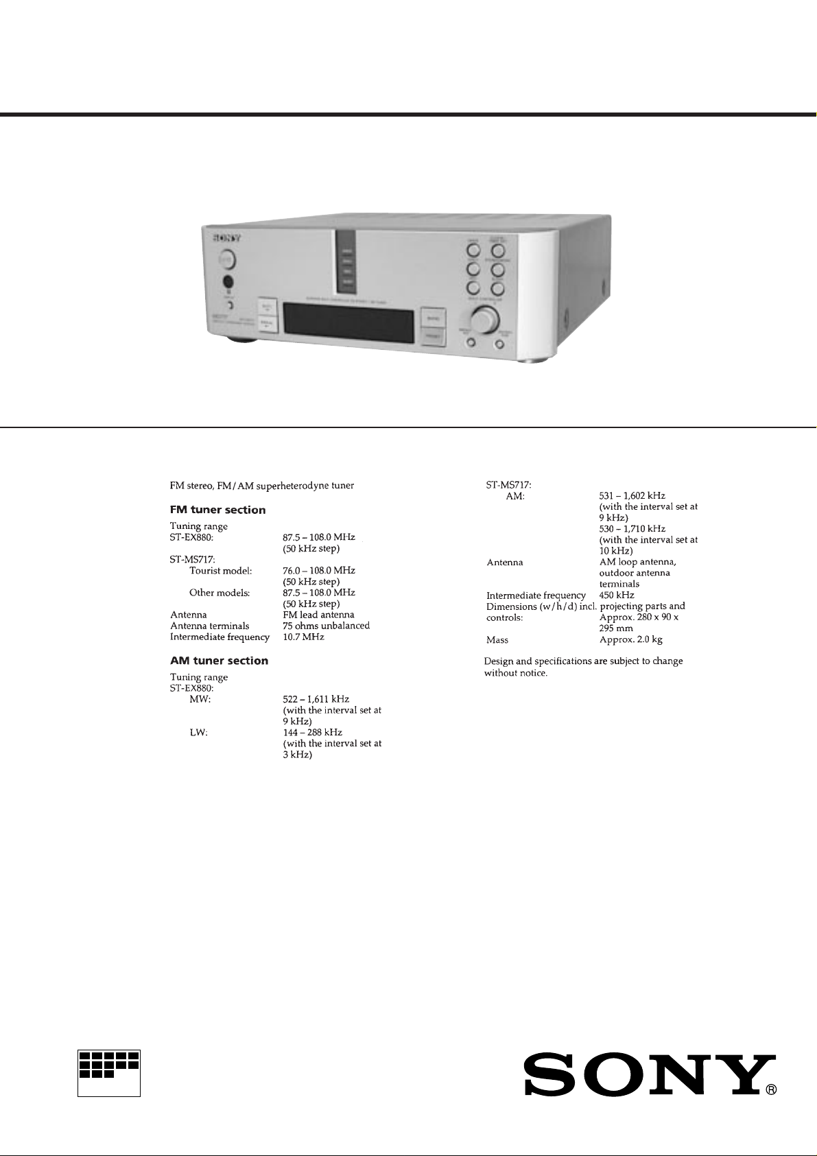
Photo: ST-MS717
SPECIFICATIONS
AEP Model
UK Model
ST-EX880
E Model
Tourist Model
ST-MS717
MICROFILM
FM STEREO/FM-AM TIMER TUNER
SECTION 1
SERVICING NOTES
TABLE OF CONTENTS
1. SERVICING NOTES ............................................... 2
2. GENERAL ................................................................... 3
3. DISASSEMBLY ......................................................... 5
4. ELECTRICAL ADJUSTMENTS......................... 6
5. DIAGRAMS
5-1. Note for Printed Wiring Boards and
Scehmatic Diagrams ....................................................... 7
5-2. Printed Wiring Board – MAIN Section –
(ST-EX880) ..................................................................... 9
5-3. Printed Wiring Board – MAIN Section –
(ST-MS717) ..................................................................... 11
5-4. Schematic Diagram – MAIN Section (1/2) – .................13
5-5. Schematic Diagram – MAIN Section (2/2) – ................. 15
5-6. Pr inted Wiring Board – PANEL Section – ..................... 17
5-7. Schema tic Diagram – PANEL Section –........................ 19
5-8. Schematic Diagram – RDS Section – (ST-EX880)........ 21
5-9. Printed Wiring Board – RDS Section – (ST-EX880) ..... 21
5-10. Schematic Diagram – POWER Section – ...................... 22
5-11. Printed Wiring Boards – POWER Section –.................. 23
5-12. IC Pin Function Description ........................................... 25
6. EXPLODED VIEWS ................................................ 29
KEYs FLUORESCENT INDICATOR TUBE/LEDs
CHECK MODE (Work a separately)
1. Press [POWER] button.
2. Press two buttons [POWER] and [SLEEP] simultaneously.
3. LEDs are all turned on, the fluorescent indicator tube displays
“KEY/FL/LED”, and the check mode is set.
1 All LED indicators light on mode
↓
2 All Fluorescent indicator tube light on mode
↓
3 ST segment mode
↓
4 RDS segment mode
↓
5 Encoder and key check mode
Note:
1) All LED light on mode is kept, when buttons which is pressed to
enter all LED light on mode, release same time.
When release them separate timing, it is moved to next All Fluorescent indicator tube light on mode.
2) After all LED light on mode, light on point remove one by one, when
any button pressed or [MULTICONTROLLER] knob turned.
3) Under KEY check mode, every time buttons pressed numerical value
of “KEY=” in FL tube increase.
And that time, numerical value of “ECDR=” increase when
[MULTICONTROLLER] button turn to + direction, and it decrease
turn to – direction.
7. ELECTRICAL PARTS LIST ............................... 31
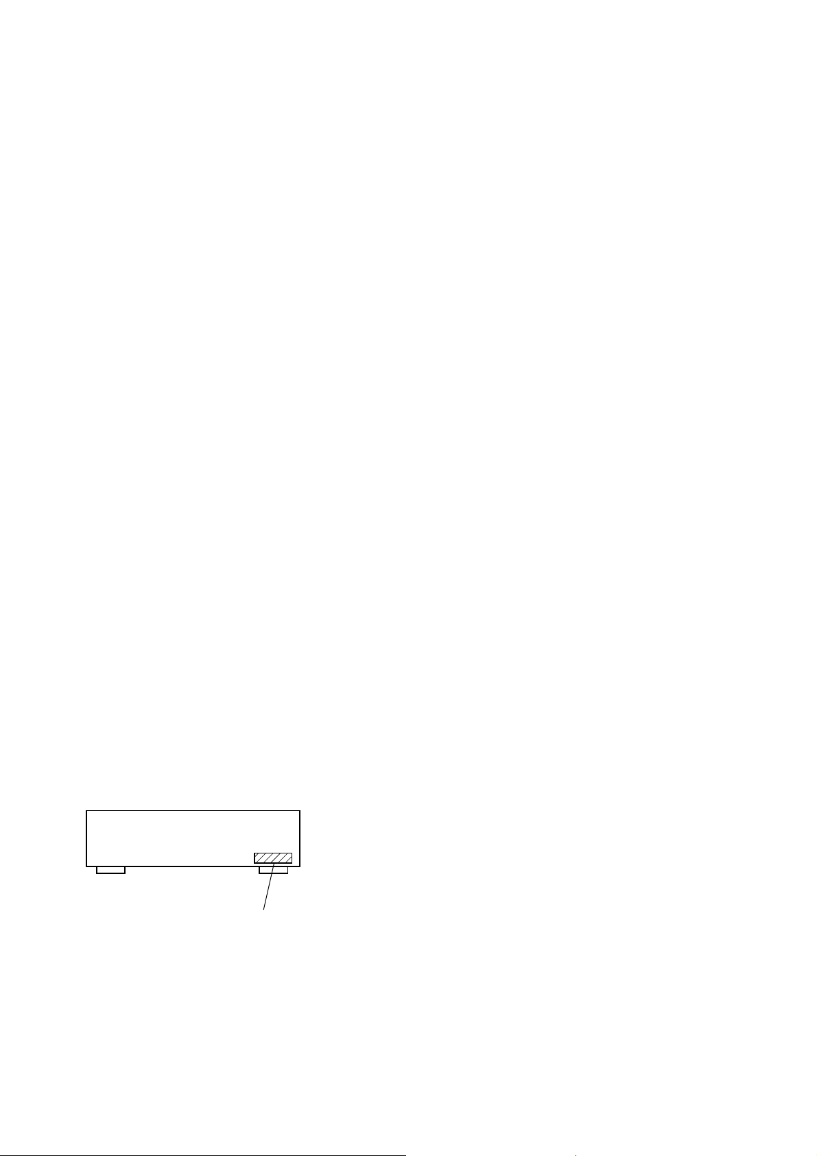
MODEL IDENTIFICATION
– Back Panel –
4-995-091-1π: Hong Kong, Singapore, Malaysia
4-995-091-2
4-995-091-3
π
: AEP, UK
π
: Tourist
To exit from this mode, disconnect the power cord.
TUNER CHECK MODE (Work a separately)
1. Press [POWER] button.
2. Press two buttons [POWER] and [ENTER/YES] simultaneously ,
and the tuner check mode is set.
3. System power on, set up the tuner function, and test condition
inactive.
Press two buttons [POWER] and [ENTER/YES] simultaneously
to exit, and system power off.
COLD RESET (Work a complex)
The cold reset clears each unit microcomputer memory to initial
conditions.
1. Press [POWER] button to turn the set OFF.
2. Press three buttons [MENU/NO], [PRESET], and [POWER]
simultaneously.
3. A message “COLD SET OK” is displayed on the fluorescent
indicator tube two seconds.
4. Press [POWER] button to turn the set OFF.
5. Remove power cord after the clock is displayed on the fluorescent indicator tube.
6. Connect power cord, press [POWER] button to turn the set
ON, and the set is reset.
SAFETY-RELATED COMPONENT WARNING!!
COMPONENTS IDENTIFIED BY MARK ! OR DOTTED
LINE WITH MARK ! ON THE SCHEMATIC DIAGRAMS
AND IN THE PARTS LIST ARE CRITICAL TO SAFE
OPERATION. REPLACE THESE COMPONENTS WITH
SONY PARTS WHOSE PART NUMBERS APPEAR AS
SHOWN IN THIS MANUAL OR IN SUPPLEMENTS PUBLISHED BY SONY.
– 2 –
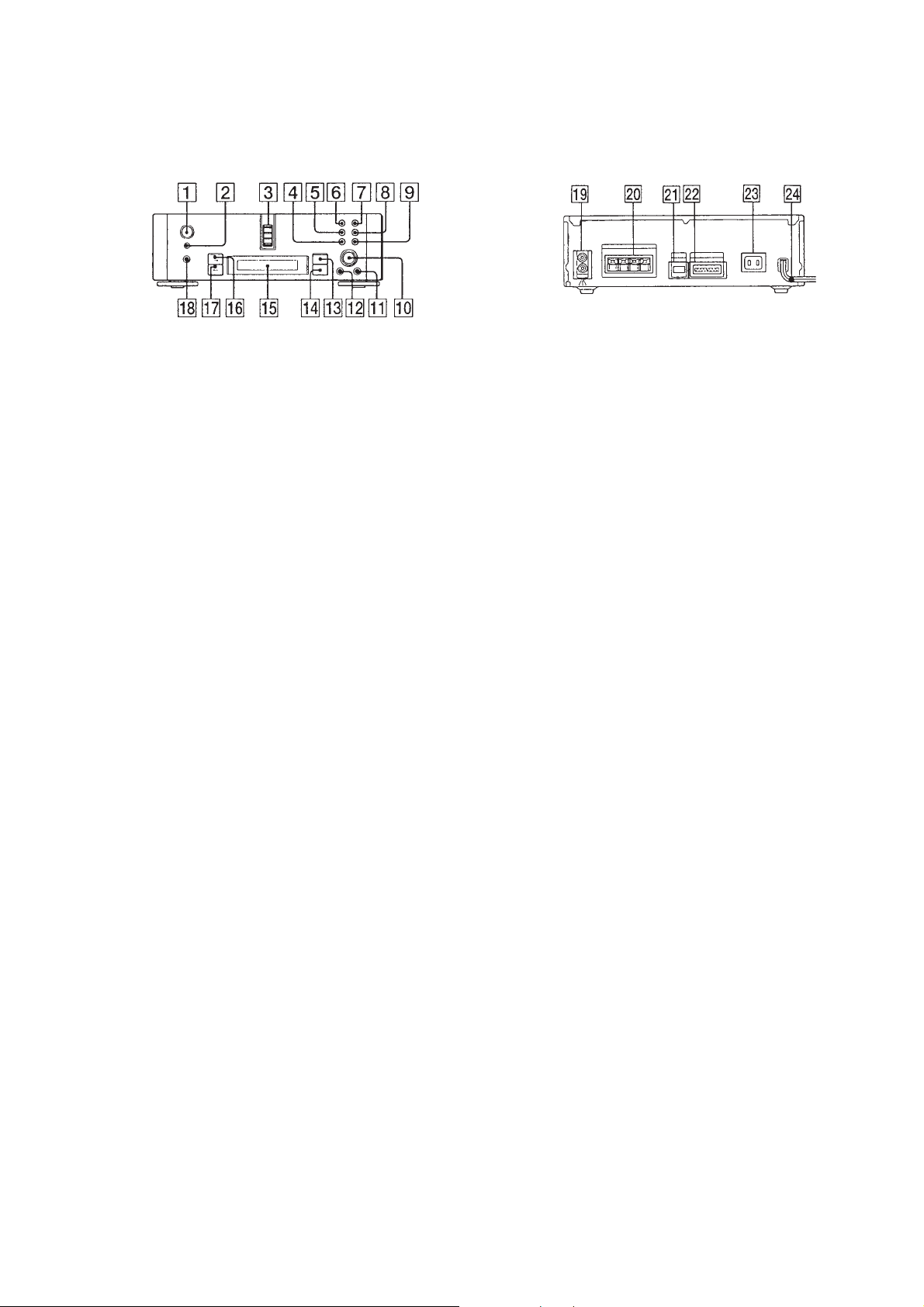
LOCATION OF CONTROLS
SECTION 2
GENERAL
This section is extracted from
instruction manual.
– Front Panel –
1 I/u (POWER) button
2 REMOTE CONTROL receiver
3 ONCE, DAILY, REC, SLEEP indicator
4 REC button
5 DAILY button
6 ONCE button
7 CLOCK/TIMER SET button
8 STEREO/MONO button
9 SLEEP button
!º MULTI CONTROLLER knob
!¡ ENTER/YES button
!™ MENU/NO button
!£ BAND button
!¢ RESET button
!∞ Fluorescent indicator tube
!§ AUTO/n button
!¶ MANUAL/N button
!• DISPLAY button
– Rear Panel –
!ª TUNER OUT terminal
@º FM/AM ANTENNA terminal
@¡ AU BUS terminal
@™ SYSTEM CONTROL terminal
@£ AC OUTLET (for TA-MS717)
@¢ POWER cord
– 3 –
– 4 –
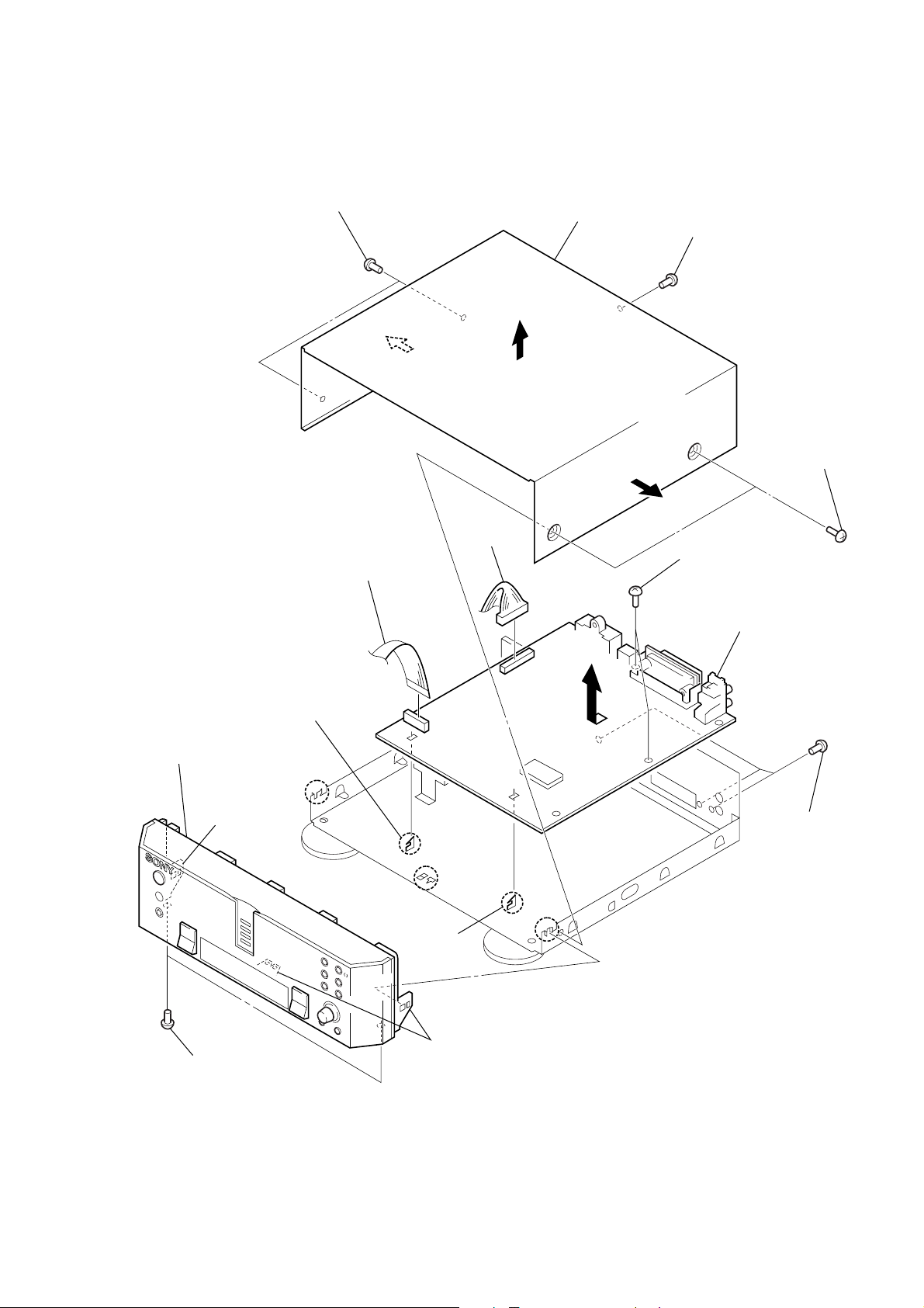
SECTION 3
3
case
0
three screws
(BVTP3
×
10)
1
two screws
(case3 TP2)
4
flat type wire (19 core)
(CN102)
!¡
claw
7
two claws
6
two screws
(BVTT3
×
6)
7
claw
8
front panel ass’y
5
connector
(CN104)
!¡
claw
!™
MAIN board
9
two screws
(BVTP3
×
8)
1
two screws
(case3 TP2)
2
screw
(BVTT3
×
6)
DISASSEMBLY
Note: Follow the disassembly procedure in the numerical order given.
MAIN BOARD
– 5 –
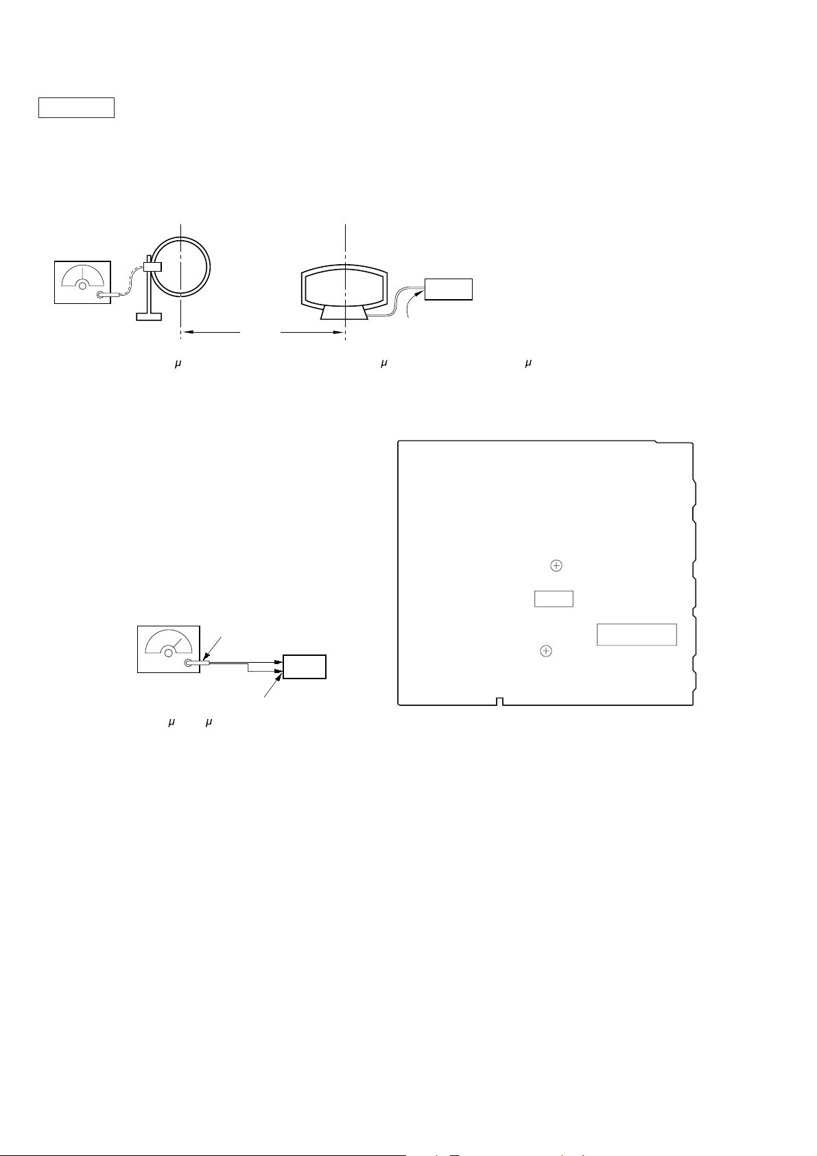
SECTION 4
l
ELECTRICAL ADJUSTMENTS
0 dB=1 µV
Note: As a front-end (FE1) is difficult to repair if faulty, replace it with
new one.
AM Section Adjustment
Setting:
loop antenna
AM RF SSG
30% amplitude
modulation by
400 Hz signal
Carrier frequency: 999 kHz (at 9 k step)
Output level : 25 dB
1,000 kHz (at 10 k step)
60 cm
loop antenna
(Supplied accessories)
Field strength dB (
set
AM ANTENNA
terminal
µ
V/m) =SSG output level dB (µV/m) –26 dB.
AM Tuned Level Adjustment
Band: AM or MW
Procedure:
1. Set the output of SSG so that the input level of the set becomes 55 dBµ/m.
2. Tune the set to 999 kHz or 1,000 kHz.
3. Adjust RV1 to the point (moment) when the TUNED indicator will change from going off to going on.
Adjustment Location : MAIN board
FM Section Adjustment
Note: This adjustment should be performed after the AM Tuned Level
Adjustment due to the same adjustment element.
Setting:
FM RF stereo signal
generator
Ω
coaxial
75
set
Carrier frequency: 98 MHz
Modulation : AUDIO 1 kH, 75 kHz
Output level : 26 dB
deviation (100%)
µ
(17.8 µV)
FM ANTENNA termina
(75 Ω open)
FM Tuned Level Adjustment
Band: FM
Procedure:
1. Supply a 26 dBµ 98 MHz signal from the ANTENNA terminal.
2. Tune the set to 98 MHz.
3. If the TUNED indicator does not light, adjust R V2 to the point
(moment) when the TUNED indicator will change from going
off to going on.
Adjustment Location: MAIN board
Adjustment Location:
[MAIN BOARD] (Component Side)
RV1
IC1
FE1
RV2
– 6 –
SECTION 5
d
DIAGRAMS
ST-EX880/MS717
5-1. NOTE FOR PRINTED WIRING BOARDS AND SCHEMATIC DIAGRAMS
Note on Schematic Diagram:
• All capacitors are in µF unless otherwise noted. pF: µµF
50 WV or less are not indicated except for electrolytics
and tantalums.
• All resistors are in Ω and 1/
specified.
¢
•
• 2 : nonflammable resistor.
• C : panel designation.
Note: The components identified by mark ! or dotted line
• U : B+ Line.
• V : B– Line.
• H : adjustment for repair.
• Voltages and waveforms are dc with respect to ground
• Voltages are taken with a V OM (Input impedance 10 MΩ).
• Waveforms are taken with a oscilloscope.
• Circled numbers refer to waveforms.
• Signal path.
: internal component.
with mark ! are critical for safety.
Replace only with part number specified.
under no-signal (detuned) conditions.
no mark : FM
( ) : AM (MW)
〈〈 〉〉 : STAND BY
[ ] : MUTING ON
Voltage variations may be noted due to normal production tolerances.
Voltage variations may be noted due to normal production tolerances.
F : FM
f : AM (MW)
4
W or less unless otherwise
Note on Printed Wiring Boards:
• X : parts extracted from the component side.
¢
•
• Indication of transistor.
Abbreviation:
: internal component.
Q
B
CE
These are omitted.
HK : Hong Kong
JE : Tourist
MY : Malaysia
SP : Singapore
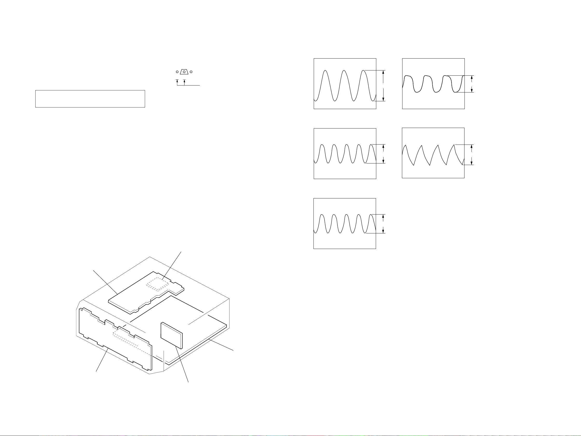
• Wavef orms
– MAIN Section –
1 IC51 1 (XIN)
4.5 MHz
2 IC201 $¡ (X2)
10 MHz
3 IC201 $¢ (XT2)
2.9Vp-p
4.4Vp-p
– PANEL Section –
4 IC901 @º (XOUT)
5.2Vp-p
513 kHz
5 IC901 @¡ (XIN)
880 mVp-p
504 kHz
• Circuit Boards Location
TRANSFORMER board
4.8Vp-p
AC OUTLET board
(Tourist model)
32.768 kHz
MAIN boar
PANEL board
RDS board
(ST-EX880)
– 7 – – 8 –
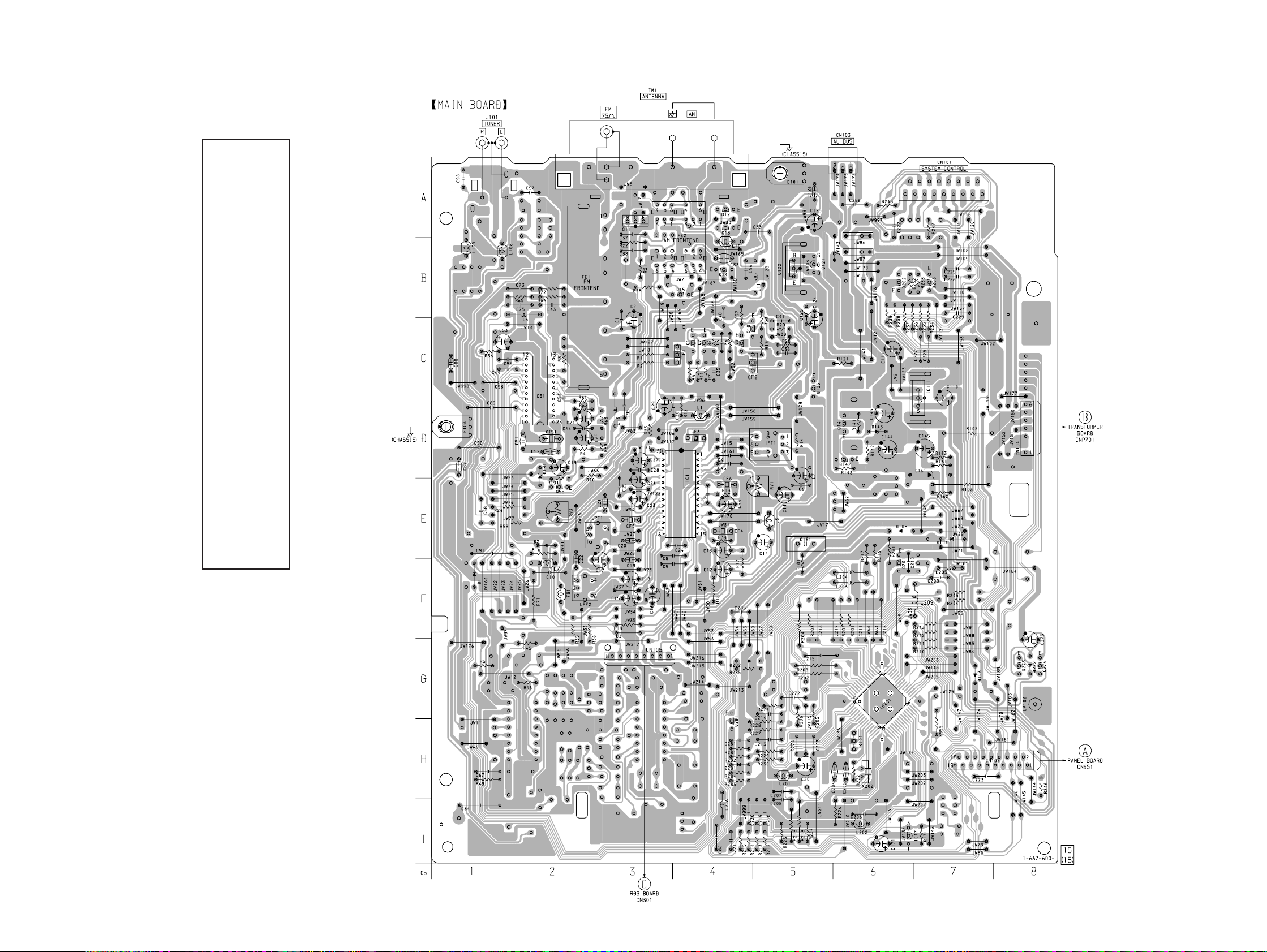
ST-EX880/MS717
5-2. PRINTED WIRING BOARD – MAIN Section – (ST-EX880)
• See page 7 for Circuit Boards Location.
• Semiconductor
Location
Ref. No. Location
D1 F-1
D2 E-2
D103 G-7
D104 E-7
D105 E-6
D125 B-5
D143 D-6
D161 D-7
D191 D-2
D272 G-8
D281 H-4
D282 G-4
IC1 E-4
IC51 C-2
IC111 C-7
IC171 I-6
IC201 G-6
Q1 C-4
Q2 C-4
Q9 C-4
Q10 C-5
Q11 A-3
Q12 A-4
Q13 A-4
Q14 B-4
Q15 B-4
Q55 E-2
Q121 B-5
Q122 B-5
Q123 C-5
Q141 D-6
Q142 D-6
Q201 F-6
Q202 B-6
Q203 B-7
Q273 G-8
Q274 G-8
Q281 H-4
(Page 24)
(Page 21)
– 9 – – 10 –
(Page 20)
 Loading...